

Page 1
Life Safety, Security and Security Assurance
Where T
rust is Built
Where T
rust is Built
INSTALLATION INSTRUCTIONS
ML-1500 SERIES ELECTROMAGNETIC LOCK
The ML-1500 Series ElectroMagnetic Lock is mounted to the
underside of the header, on the stop side of the door.
The armature is mounted to the door. A hardware kit is provided to
compensate for misalignment and wear of the door, by allowing the
armature to pivot on it’s center point.
P/N 103162 September 18, 2008
Detex Corporation
302 Detex Drive
New Braunfels , Texas 78130
www.detex.com Tel : (800) 729-3839
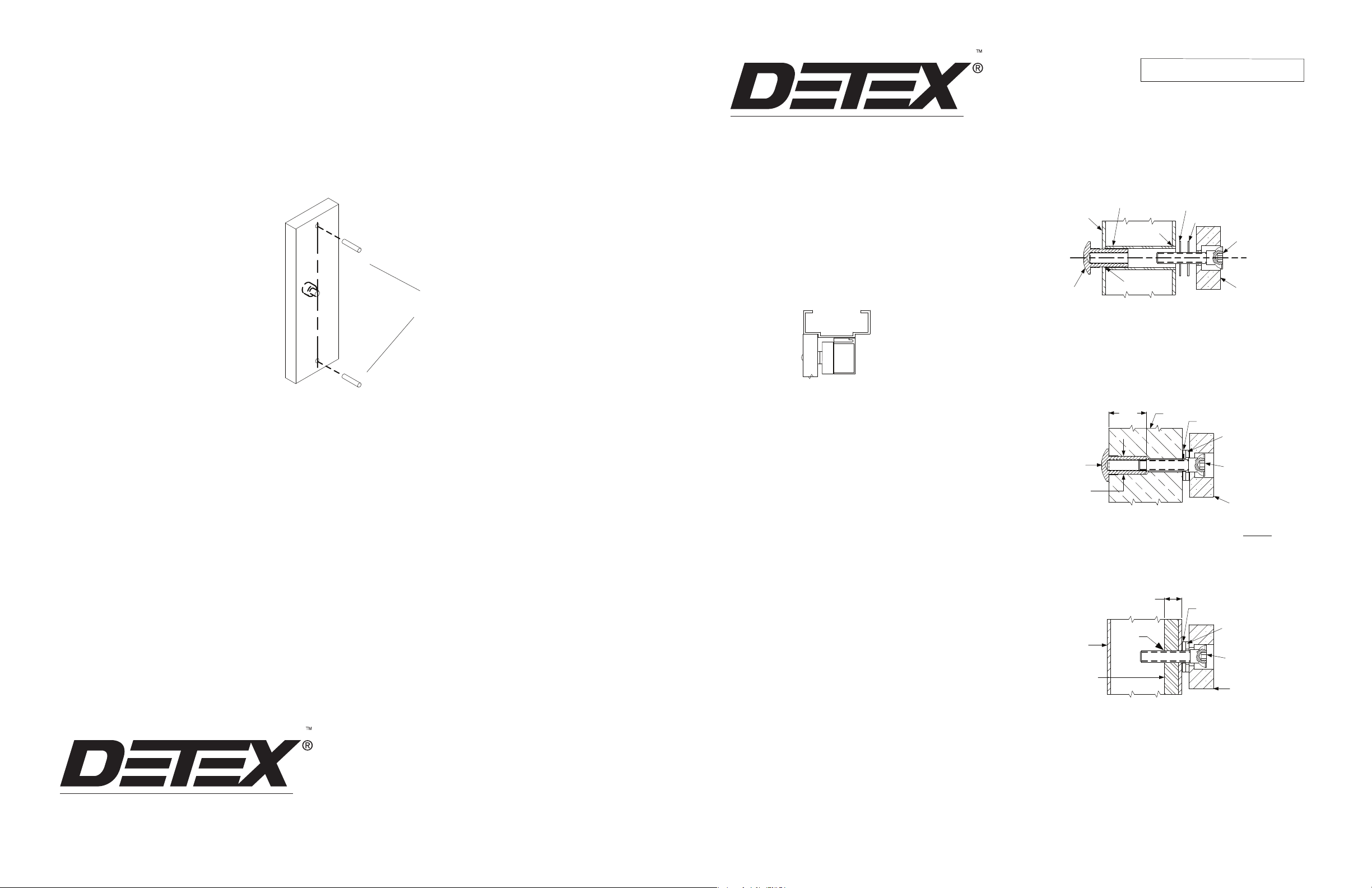
1-3/4“ HOLLOW
METAL DOOR
REINFORCEMENT
TUBE
5/8“ DRILL
STEEL WASHER
RUBBER WASHER
5/16-18 SOC HD
SCREW
WITH 3/16 (5MM)
ALLEN HEX
Add both spring pins to armature
1. Inspect the frame header to determine if an angle bracket or filler plate
is required. See Figure 1 for Regular mounting.
Alternative mounting on page 3.
FIG. 1
Regular
2. Fold template as indicated by dotted line. For single doors, locate
template against the door and header on the lock jamb side of the
frame.
3. Mark and drill holes as indicated by template . For armature plate hole
preparation, see Figure 2A, 2B, 2C.
3A. Add both spring pins to armature plate. See page 4.
4. Mount armature to door. To determine proper hardware (provided), see
Figure 2A, 2B, 2C.
Install mounting plate to header with the interlock detail away from the
5.
door side of the stop, with #10 Flt Hd. Screws provided.
6. Holding the magnet housing at each end, engage the entire
length of the interlock detail, by pushing towards the door.
(If necessary, tap with a soft hammer to ensure proper alignment
and engagement).
Caution: The lock body must be held in place until
secured with mounting screws. Screws provided inside the
housing at each end. Tighten the screws and check alignment.
7.
Remove front plate to access electronics. See page 2 for wiring.
8. Test operation. When all is operating properly, tighten all
screws. Install anti-tamper plugs over socket head screw
using a soft hammer to avoid damage to the housing.
Electromagnet and armature should be handled carefully.
Any damage to the surface such as paint, burrs, dirt and rust
may hinder bonding of surface and reduce holdi
ng power.
SEXNUT
1/2” DRILL
ARMATURE
FIG. 2A HOLLOW METAL DOOR
From Sexnut side of door, drill exactly 1/2” hole thru one metal thickness
only. From Armature side of door, drill 5/8” hole to insert reinforcement
tube. Press in sexnut and reinforcement tube all the way and mount
armature to door using hard
1-3/8“
SEXNUT
1/2“
Drill 3/8” hole thru door. From sexnut side of door, drill exactly
ware provided per Figure 2B.
DOOR
WASHER
RUBBER
WASHER
5/16-18 SOC HD
SCREW
WITH 3/16 (5 MM)
ALLEN HEX
ARMATURE
1/2” hole,
1-3/8” deep. Mount armature to door with hardware provided per Figure 2A.
FIG. 2B SOLID DOOR
3/8“ MIN
DOOR
Reinforcement
by others
METAL
5/16-18
WASHER
Add as required
WASHER
RUBBER
5/16-18 SOC HD
SCREW
WITH 3/16 (5MM)
ALLEN HEX
ARMATURE
Life Safety, Security and Security Assurance
Page 4 103162
SHOULD THE SURFACE PLATING BE DAMAGED:
Do not touch the lock face with your hands.
Using a soft, clean, dry cloth or abrasive cloth (i.e., Scotch-Brite),
clean lock face. Do not use sand paper.
A rust inhibitor such as M1, manufactured by Starret, or LPS3,
manufactured by LPS Laboratories (available at most hardware stores)
can then be applied. Apply a coat of inhibitor to armature face al
so.
Drill and tap for 5/16-18 machine screw. Mount
FIG. 2C REINFORCED DOOR
armature to door with hardware provided per Figure 2C.
Page 1 103162
Page 2
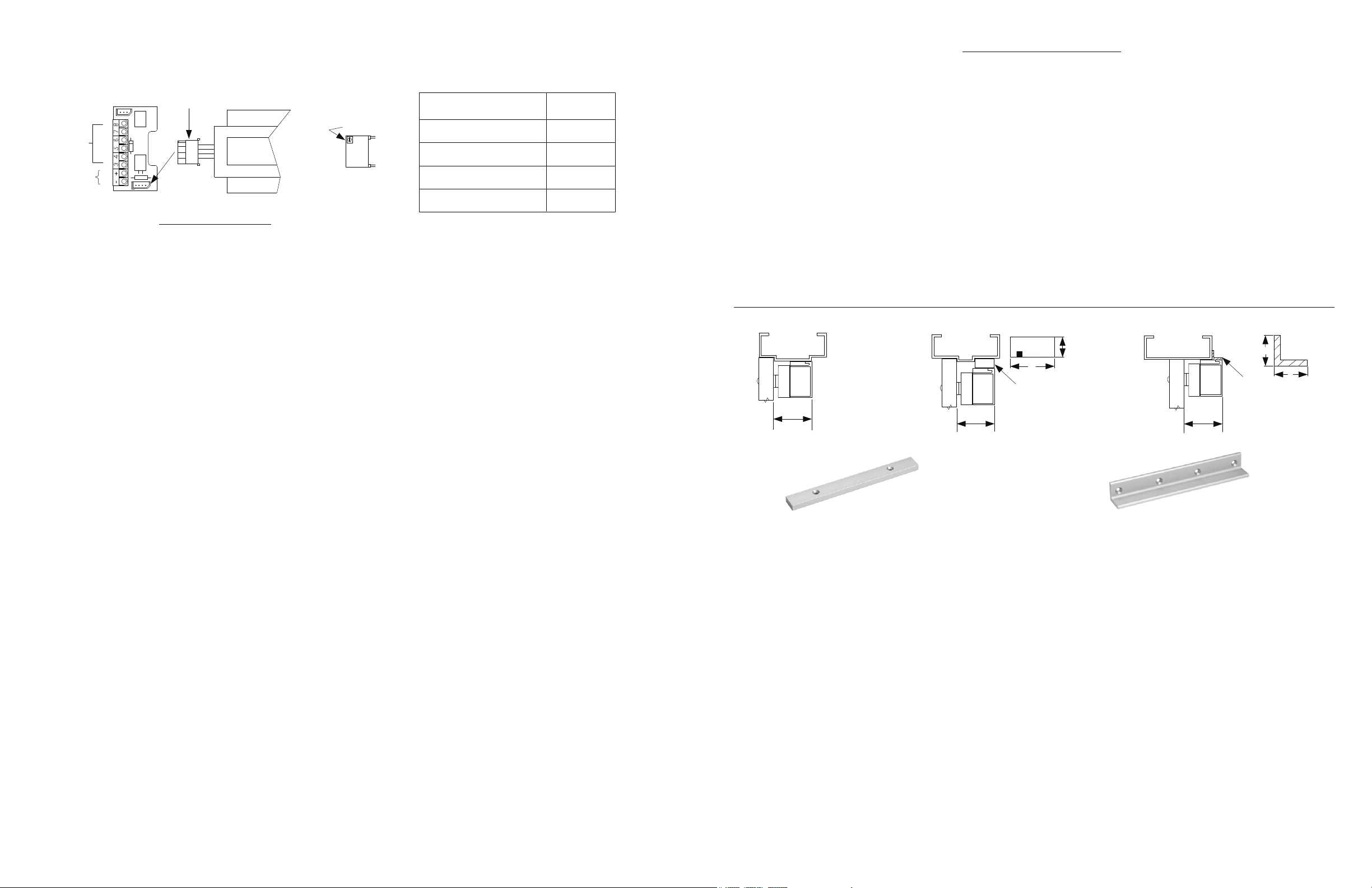
LOCK PWR
ML-1500 Series Connections
ELECTROMAGNET
PLUG CONNECTION
E1
E2
Not Used
+
-
J1
E3
E4
FIG. 3
AVAILABLE OPTIONS
RT TIME DELAY (1-30 sec)
*NOTE: For a proper coil resistance reading, turn off the DC voltage. Use an ohmmeter and measure
the resistance between the pins of the plug connector positions E1-E2 and E3-E4
LOCK
ELECTRICAL SPECIFICATIONS
Voltage kickback protection standard
SERIES
TIME ADJ.
RT
INPUT VOLTAGE (VDC)
POWER CONSUMPTION (mA)
COIL RESISTANCE (OHMS)
HOLDING FORCE (LBS)
ML-1500
35 (PER COIL)*
24
350
1650
TROUBLE SHOOTING .
Problem
ElectroMagnetic lock releases
Cause
Control switdch wired on DC side of power source
Solution
Control switch must be wired on DC side of power supply.
slowly. (residual magnetism)
Poor holding force.
Armature installed rigidly.
Low voltage
Armature must pivot loosely from its center mounting point to
t full armature contact.
permi
Check for proper voltage at the ElectroMagnetic lock input. If
low, determine if the correct wire guage is being used to
prevent excessive voltage drop.
No holding force
No power Check power supply load capacity. It must meed or exceed
the combined current rating of all locks on the circuit.
Door does not lock. Input polarity reversed. ElectroMagnetic locks require DC
Open circuit in ElectroMagnetic Lock coil .
Check coil continuity with OHM meter. If reading is high
or open, replace the magnet coil. See Fig. 3 and the
Resitance Specifications.
Magnet coil short.
Coil shorts or incorrect wiring will blow fuses.
Measure the coil for correct resitance. See Fig. 3
and the Resitance Specifications.
input voltage.
ELECTRICAL INSTALLATION
IMPORTANT NOTES
INDOOR USE ONLY
1. Use jacketed cable for all wire runs. Refer to the AWG wire
gauge chart for proper lock power wire size (18 AWG
Do not run power wires and signal wire
cable or conduit.
s in the same
gauge minimum).
2. All wires must be colored coded.
3. Use properly fused power source only. See Electrical
Specifications.
4. Make all ElectroMagnetic Lock terminal connections according to
Figure 3
AWG WIRE CHART
To determine the correct wire gauge to use on “one circuit” the following information is required:
1. The quantity, voltage, and current draw of all lock(s) to be used.
2. The distance in feet from the power supply to the furthest lock.
Add together the current draw (amps) of all locks on the same circuit. Cross reference the total amps with the distanc
e between the
power source and the furthest lock to determine the wire gauge required. All wiring must be installed in accordance with all state and
local codes.
DISTANCE IN FEET FROM POWER SOURCE TO FARTHEST LOCKING DEVICE
Figure 1
Regular
2-5/16"
59mm
Filler Plate
P/N 103916
FILLER PLATES: For extension of the stop to provide a
proper mounting surface on the underside of the header.
See Figure 1B.
FOR ML-1500 SERIES MODELS
PART #
103916
SIZE
A
B
5/8” x 1-1/4" x 11" (16 x 32 x 279mm)
Figure 1B
2-5/16"
59mm
A
B
Filler
Plate
ANGLE BRACKETS: Used as extension on shallow door
frames to provide adequate mounting surface.
See Figure 1C.
FOR ML-1500 SERIES MODELS
PART #
SIZE BA
103917
Figure 1C
Angle Bracket
2-5/16"
59mm
P/N 103917
2” x 1-1/2" x 11" LG (51 x 3
B
Angle
Bracket
8 x 279mm)
A
Minimum
Wire
Gauge for
24 Volts
DC
AMPS
0.25
0.50
0.75
1.00
1.50
2.00
2.50
25 50 75 100 150 200 250 300 400 500 1000
18 18 18 18 18 18 18 18 16 16 16
18 18 18 18 18 16 16 14 14 12
18 18 18 18 16 14 14 12 12
18 18 16 16 14 14 12 12
18 18 1
6 14 14 12
18 16 14 14 12
18 16 14 12
Page 2 103162
Available kits:
Armature hardware kit P /N 103918-1
ElectroMagnetic lock hardware kit P /N 103918-2
Page 3 103162
 Loading...