

Page 1
IEI prox.pad™ Proximity Reader/Keypad
Access Control Installer Guide
Now Part of
This Installer Guide is designed as a reference document for experience installers only. It is not intended for routine use and
does not replace the more comprehensive information supplied in the prox.pad Installation/Programming Manual located on
the included CD-ROM. You can also download the reference manual from our website at www.linearcorp.com.
Please refer to the table of contents and list of illustrations on the inside cover.
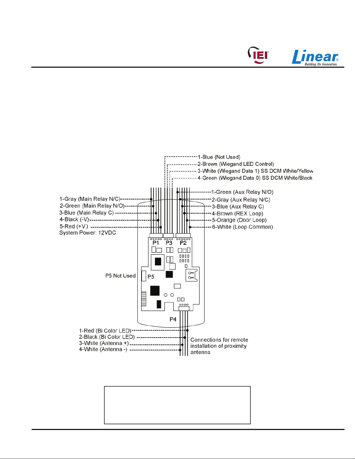
prox.pad Pin Connector Diagram
The diagram below shows all the wire harness connectors on the main circuit board and their functions.
Document # 6-055678 X2
Figure 1: Identifying Pin Connectors
15.21 Information to User
Any changes or modifi cations not expressly approved
by the party responsible for compliance could void the
user’s authority to operate the equipment.
Page 1 of 32
Page 2

Prox.pad Installer Guide
Table of Contents
prox.pad Pin Connector Diagram . . . . . . . . . . . . . . . . . . . . . . . . . . . . . . . . . . . . . . . . . . . . . . . . . . . . . . . . . . . . . . . . . . . . 1
prox.pad Pin Connector Table . . . . . . . . . . . . . . . . . . . . . . . . . . . . . . . . . . . . . . . . . . . . . . . . . . . . . . . . . . . . . . . . . . . . . . . 3
Supplied Parts/Optional Items . . . . . . . . . . . . . . . . . . . . . . . . . . . . . . . . . . . . . . . . . . . . . . . . . . . . . . . . . . . . . . . . . . . . . . . 4
prox.pad Specifications . . . . . . . . . . . . . . . . . . . . . . . . . . . . . . . . . . . . . . . . . . . . . . . . . . . . . . . . . . . . . . . . . . . . . . . . . . . . 5
Mounting the prox.pad Unit . . . . . . . . . . . . . . . . . . . . . . . . . . . . . . . . . . . . . . . . . . . . . . . . . . . . . . . . . . . . . . . . . . . . . . . . . 7
Performing a Wall Mounted Installation . . . . . . . . . . . . . . . . . . . . . . . . . . . . . . . . . . . . . . . . . . . . . . . . . . . . . . . . . . . . . 7
Performing a Glass Mounted Installation . . . . . . . . . . . . . . . . . . . . . . . . . . . . . . . . . . . . . . . . . . . . . . . . . . . . . . . . . . . 8
Performing a Secure Installation . . . . . . . . . . . . . . . . . . . . . . . . . . . . . . . . . . . . . . . . . . . . . . . . . . . . . . . . . . . . . . . . . . 9
Installing a Tamper Switch . . . . . . . . . . . . . . . . . . . . . . . . . . . . . . . . . . . . . . . . . . . . . . . . . . . . . . . . . . . . . . . . . . . . . . . . . 11
Mounting over a metal or plastic single gang J-Box . . . . . . . . . . . . . . . . . . . . . . . . . . . . . . . . . . . . . . . . . . . . . . . . . . 11
Wall mounting . . . . . . . . . . . . . . . . . . . . . . . . . . . . . . . . . . . . . . . . . . . . . . . . . . . . . . . . . . . . . . . . . . . . . . . . . . . . . . . 11
Inserting Circuit Boards . . . . . . . . . . . . . . . . . . . . . . . . . . . . . . . . . . . . . . . . . . . . . . . . . . . . . . . . . . . . . . . . . . . . . . . . . . . 12
Defaulting prox.pad Memory . . . . . . . . . . . . . . . . . . . . . . . . . . . . . . . . . . . . . . . . . . . . . . . . . . . . . . . . . . . . . . . . . . . . . . . 13
Standalone Mode Default Settings . . . . . . . . . . . . . . . . . . . . . . . . . . . . . . . . . . . . . . . . . . . . . . . . . . . . . . . . . . . . . . . . . . 14
Standalone Mode LED Indicators/Sounder Operations . . . . . . . . . . . . . . . . . . . . . . . . . . . . . . . . . . . . . . . . . . . . . . . . . . . 15
Standalone Mode Wiring . . . . . . . . . . . . . . . . . . . . . . . . . . . . . . . . . . . . . . . . . . . . . . . . . . . . . . . . . . . . . . . . . . . . . . . . . . 16
Wiring an External REX Switch (Request to Exit) . . . . . . . . . . . . . . . . . . . . . . . . . . . . . . . . . . . . . . . . . . . . . . . . . . . . . . . 19
Standalone Mode Program Commands . . . . . . . . . . . . . . . . . . . . . . . . . . . . . . . . . . . . . . . . . . . . . . . . . . . . . . . . . . . . . . 20
Wiring a Wiegand Front End . . . . . . . . . . . . . . . . . . . . . . . . . . . . . . . . . . . . . . . . . . . . . . . . . . . . . . . . . . . . . . . . . . . . . . . 24
Wiegand Mode LED/Sounder States . . . . . . . . . . . . . . . . . . . . . . . . . . . . . . . . . . . . . . . . . . . . . . . . . . . . . . . . . . . . . . . . . 25
Wiegand Front End Mode Default Settings . . . . . . . . . . . . . . . . . . . . . . . . . . . . . . . . . . . . . . . . . . . . . . . . . . . . . . . . . . . . 25
Wiegand Programming Commands . . . . . . . . . . . . . . . . . . . . . . . . . . . . . . . . . . . . . . . . . . . . . . . . . . . . . . . . . . . . . . . . . 26
Wiring the Secured Series Front End . . . . . . . . . . . . . . . . . . . . . . . . . . . . . . . . . . . . . . . . . . . . . . . . . . . . . . . . . . . . . . . . 27
Secured Series Front End Mode LED Indicators/Sounder . . . . . . . . . . . . . . . . . . . . . . . . . . . . . . . . . . . . . . . . . . . . . . . . 28
Secured Series Front End Mode Default Settings . . . . . . . . . . . . . . . . . . . . . . . . . . . . . . . . . . . . . . . . . . . . . . . . . . . . . . . 28
Secured Series Programming Commands . . . . . . . . . . . . . . . . . . . . . . . . . . . . . . . . . . . . . . . . . . . . . . . . . . . . . . . . . . . . 29
Technical Support . . . . . . . . . . . . . . . . . . . . . . . . . . . . . . . . . . . . . . . . . . . . . . . . . . . . . . . . . . . . . . . . . . . . . . . . . . . . . . . 30
Warranty . . . . . . . . . . . . . . . . . . . . . . . . . . . . . . . . . . . . . . . . . . . . . . . . . . . . . . . . . . . . . . . . . . . . . . . . . . . . . . . . . . . . . . 30
List of Illustrations
Figure 1: Identifying Pin Connectors . . . . . . . . . . . . . . . . . . . . . . . . . . . . . . . . . . . . . . . . . . . . . . . . . . . . . . . . . .1
Figure 2: Performing a Wall Mounting Installation . . . . . . . . . . . . . . . . . . . . . . . . . . . . . . . . . . . . . . . . . . . . . . . .7
Figure 3: Performing a Glass Mounted Installation . . . . . . . . . . . . . . . . . . . . . . . . . . . . . . . . . . . . . . . . . . . . . . .8
Figure 4: Performing a Secure Installation . . . . . . . . . . . . . . . . . . . . . . . . . . . . . . . . . . . . . . . . . . . . . . . . . . . . .10
Figure 5: Temper Switch Locations . . . . . . . . . . . . . . . . . . . . . . . . . . . . . . . . . . . . . . . . . . . . . . . . . . . . . . . . . .11
Figure 6: Removing/Inserting Printed Circuit Board . . . . . . . . . . . . . . . . . . . . . . . . . . . . . . . . . . . . . . . . . . . . .12
Figure 7: Program Button Location on Main Circuit Board . . . . . . . . . . . . . . . . . . . . . . . . . . . . . . . . . . . . . . . .13
Figure 8: Wiring a Maglock - Fail Safe . . . . . . . . . . . . . . . . . . . . . . . . . . . . . . . . . . . . . . . . . . . . . . . . . . . . . . . .16
Figure 9: Wiring an Electric Strike - Fail Secure . . . . . . . . . . . . . . . . . . . . . . . . . . . . . . . . . . . . . . . . . . . . . . . .16
Figure 10: Wiring the Aux Relay for Alarm Shunt . . . . . . . . . . . . . . . . . . . . . . . . . . . . . . . . . . . . . . . . . . . . . . . 17
Figure 11: Wiring the Aux Relay for Forced Door . . . . . . . . . . . . . . . . . . . . . . . . . . . . . . . . . . . . . . . . . . . . . . .17
Figure 12: Wiring the Aux Relay For Propped Door . . . . . . . . . . . . . . . . . . . . . . . . . . . . . . . . . . . . . . . . . . . . . .18
Figure 13: Wiring the Door Contact . . . . . . . . . . . . . . . . . . . . . . . . . . . . . . . . . . . . . . . . . . . . . . . . . . . . . . . . . .18
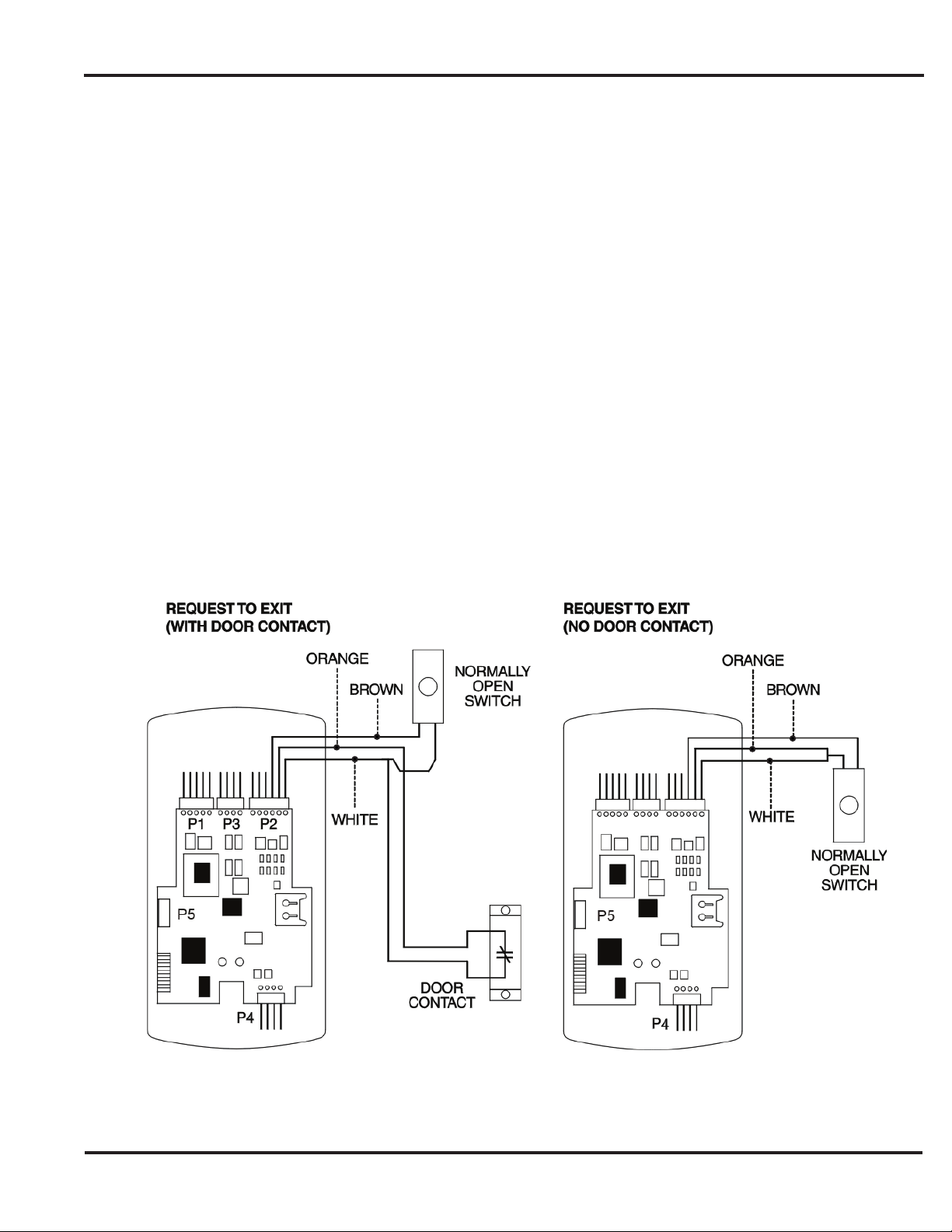
Figure 14: Wiring an External REX Switch . . . . . . . . . . . . . . . . . . . . . . . . . . . . . . . . . . . . . . . . . . . . . . . . . . . . 19
Figure 15: Connecting the prox.pad to a Wiegand Panel . . . . . . . . . . . . . . . . . . . . . . . . . . . . . . . . . . . . . . . . . 24
Figure 16: Connecting the prox.pad to a Secured Series DCM . . . . . . . . . . . . . . . . . . . . . . . . . . . . . . . . . . . . .27
Page 2 of 32
Document # 6-055678 X2
Page 3
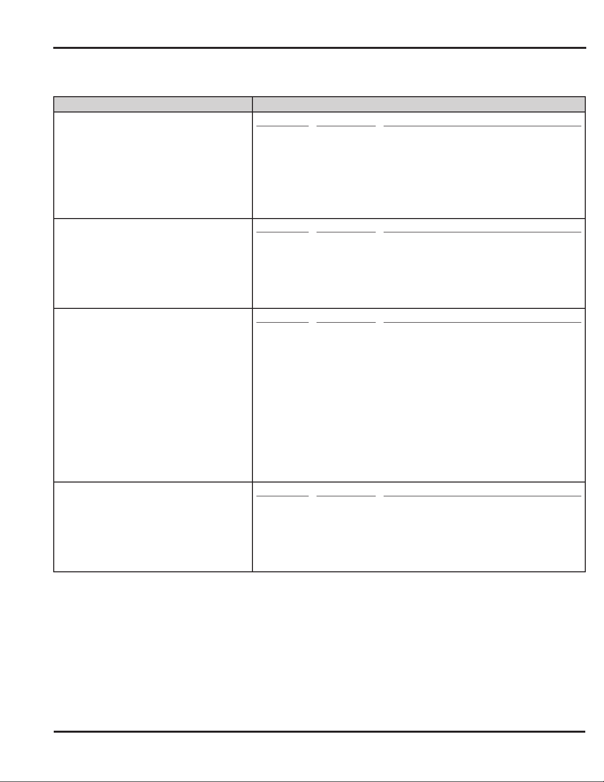
prox.pad Pin Connector Table
Pin Connector (on main circuit board) Description/Use
Pin
1
2
P1 (5-pin connector, top left-most location)
3
4
5
Wire Color
Gray
Green
Blue
Black
Red
Prox.pad Installer Guide
Use
Main Relay Normally Open
Main Relay Normally Closed
Main Relay Common
Ground (Power Supply)
+12V Input (Power Supply)
P3 (4-pin connector, top middle location)
P2 (6-pin connector, top right most location)
P4 (4-pin connector, bottom location)
Pin
1
2
3
4
Pin
1
2
3
4
5
6
NOTE: Pins 1, 2, 3 can be wired at the installer’s option for one of the
following alarm outputs, Alarm Shunt, Forced Door, or Propped Door,
Mandatory: If you are not installing door contacts per Figure 11, twist the
white and orange wires together. If not done, the REX input won’t work
Pin
1
2
3
4
Wire Color
Blue
Brown
White
Green
Wire Color
Green
Gray
Blue
Brown
Orange
White
Wire Color
Red
Black
White
White
Use
Not Used
Wiegand LED Control
Wiegand Data 1
Wiegand Data 0
Use
Aux Relay Normally Open
Aux Relay Normally Closed
Aux Relay Common
REX Loop
Door Contact Loop
Loop Common
Use
Bi-Color LED (Red +)
Bi-Color LED (Green +)l
Antenna (no polarity)
Antenna (no polarity
Document # 6-055678 X2
Page 3 of 32
Page 4
Prox.pad Installer Guide
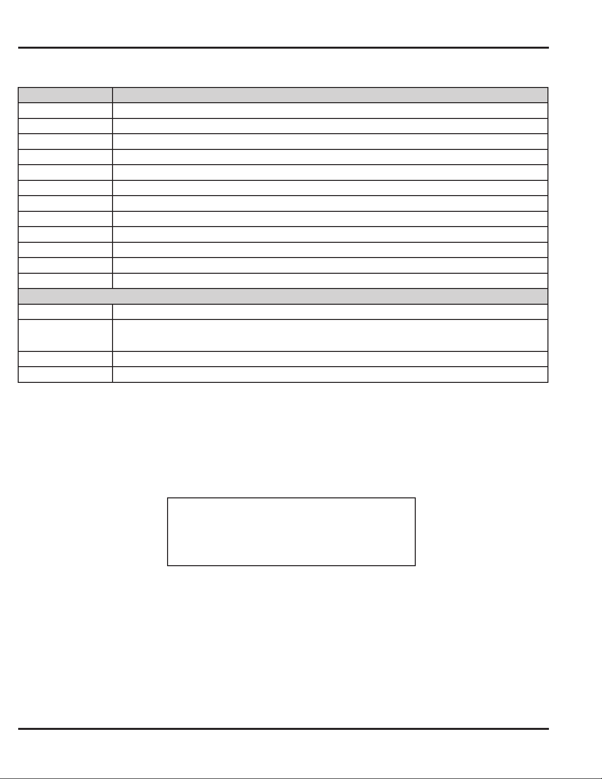
Supplied Parts/Optional Items
Quantity Description
1 Keypad/control unit assembly, with Prox Sensor, Backplate, hex socket screw
1 Filler Piece/REX Button
1 Press to Exit Label
4 Wall Anchors
4 Mounting Screws
1 Antenna Backplate for remote mounting
1 Silicone Rubber “dogbone”
4 Self-Adhering Pads (for glass mounting)
1 Installer Guide
1 CD-ROM containing instruction manuals
4 Cable Assemblies
1 Tamper Screw
Optional Items
1 Data Collection Device (to capture user list and transaction event log)
1
lots of 25 only ProxKey ProxFobs (part number 0-297301A)
lots of 25 only ProxCard II Cards (part number 0-297401)
prox.pad Replacement Battery: Panasonic BR1225, Renata CR1225 or Varta CR1225;
Refer to caution below.
Page 4 of 32
Caution: Replace battery with types listed above
only. Use of another battery may present risk of fi re or
explosion. Battery may explode if mistreated. Do not
recharge, disassemble or dispose of battery in fi re.
Document # 6-055678 X2
Page 5
Prox.pad Installer Guide
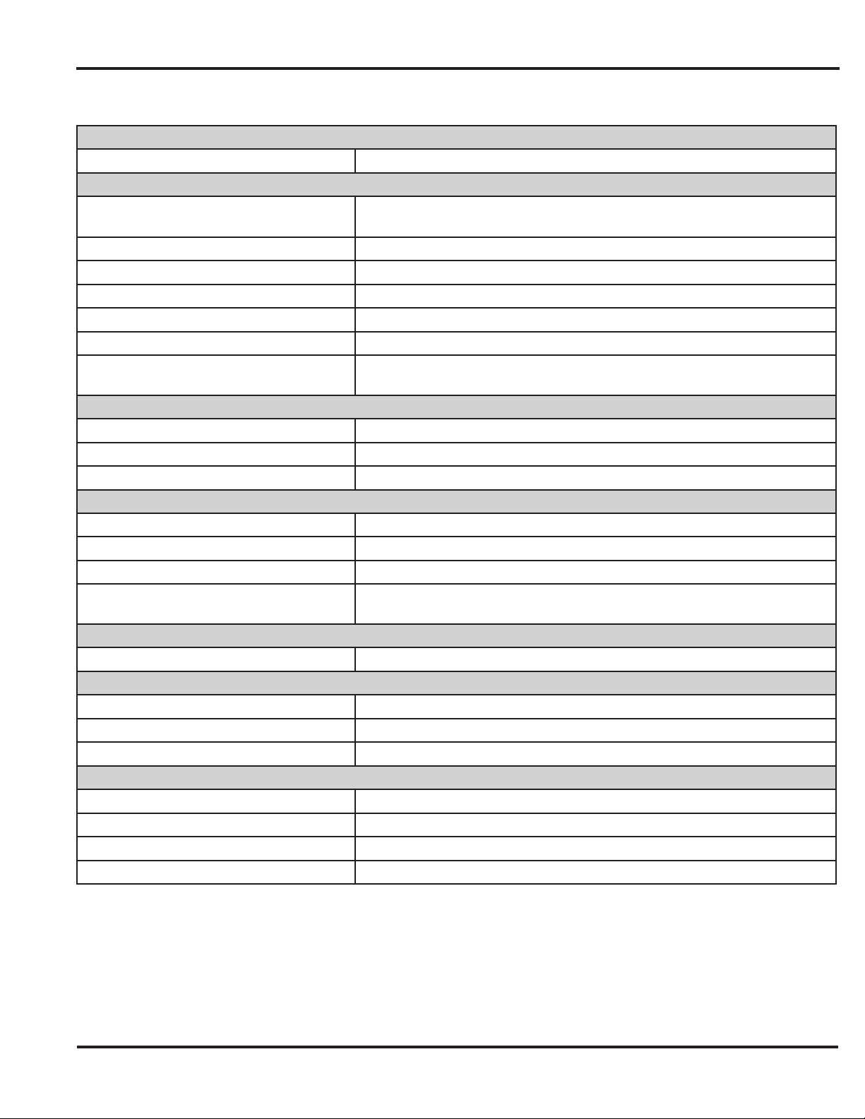
prox.pad Specifi cations
Electrical
Power Supply/Current Requirements 10-15 VDC, linear fi ltered and regulated power supply; 55mA
Wiring
Remote Antenna Cable (if installing in a
secured confi guration)
Wiegand Interface Guide [ALPHA 1295C (22AWG) 5-conductor, stranded and shielded]
Secured Series Front End Cables [ALPHA 1295C (22AWG) 4-conductor, stranded and shielded]
Power Supply Cable 18AWG - 22 AWG 2-wire stranded (depends upon distance)
Door Lock Cable 18AWG - 22 AWG 2-wire stranded (depends upon distance)
Door Monitor Cable 18AWG - 22 AWG 2-wire stranded (depends upon distance)
REX Cable
Mechanical
Height 5.25 in (13.3 cm)
Width 2.75 in (7 cm)
Depth 1.375 in (3.5 cm)
Relay Outputs
Main Relay Form C (switches up to 2A)
Aux Relay Form C (switches up to 1A)
Monitor Inputs
Door Position Switch Normally Closed, Dry Contact
Other Outputs
Sounder 4000 Hz, defeatable
Bi-Color LED Red/Green
Yellow LED
Compatible Proximity Cards (All HID cards up to 40 bits, including the following)
[ALPHA 1294C (22AWG) 4-conductor, stranded and shielded]
[ALPHA 2421C 18 AWG or ALPHA 1292C 22 AWG, 2 conductor,
stranded and shielded] (if using remote switch)
Program for either timed (1-99 sec) or toggle
One of three functions can be programmed: Alarm Shunt Relay,
Forced Door Relay, or Propped Door Relay
Prox Card II
IsoProx II
DuoProx II
Proxkey FOB
Specifi cations continued on next page.
Document # 6-055678 X2
Page 5 of 32
Page 6
Prox.pad Installer Guide
Specifi cations Continued
Unit Capacity
Users (standalone mode only) 2000 Maximum (each user can have a card, PIN or both)
Environmental (Indoor or Outdoor)
Operating Temperature -31° to 150° F (-35° to 66° C)
Operating Humidity 5% to 95% relative humidity, non-condensing
Page 6 of 32
Document # 6-055678 X2
Page 7
Prox.pad Installer Guide
Mounting the prox.pad Unit
Select one of these three installation confi gurations, wall mount, glass mount, or secure as appropriate for this installation.
Performing a Wall Mounted Installation
This section provides general considerations when performing a wall mounted installation. Typically, the prox.pad unit is
mounted on a fl at, level surface (drywall, masonry, wood, etc.) exterior to the room to be accessed. A single-gang electrical
box (or back box) can be used. Typically, the prox.pad unit is wall mounted outside the access area on the unsecured side
of the door.
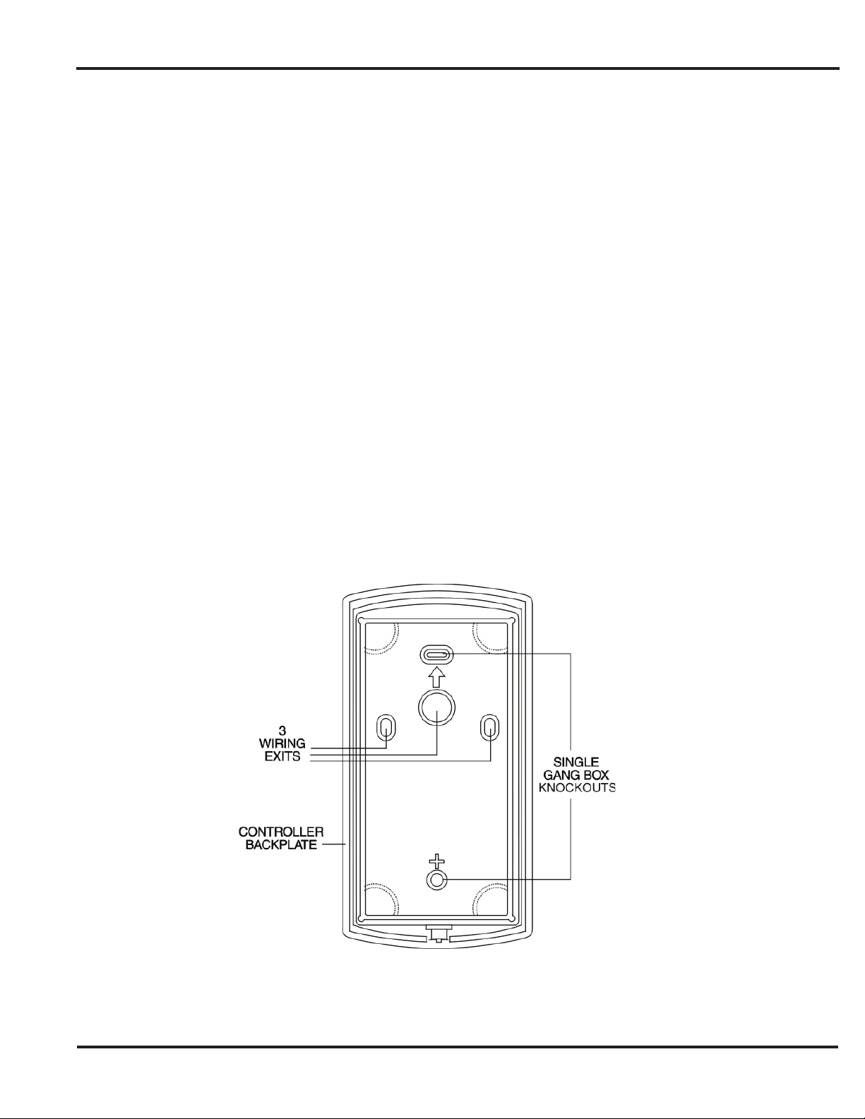
Figure 2 below illustrates the components on the prox.pad unit used for wall mounting. Two single-gang box holes align with
two corresponding holes in the single-gang box. A wire exit knockout is supplied through which the prox.pad wiring is pulled.
A typical wall mounted installation proceeds as follows:
1. Install a single-gang box in the desired location.
2. Punch out the two single-gang box knockouts on the controller backplate of the prox.pad unit.
3. Disconnect the controller backplate of the prox.pad unit from the front keypad/controller. Align the two single-gang
box holes on the controller backplate over the two corresponding holes on the single-gang box, previously secured
at step 1.
4. Secure the backplate to the single-gang box by inserting/tightening two screws into the two single-gang box holes.
5. Connect the front keypad/controller to the back housing.
6. Pull the prox.pad wiring through the wiring exit as appropriate.
7. Install the tamper screw into the hole at the bottom front of the enclosure using a #6 spanner bit.
Document # 6-055678 X2
Figure 2: Performing a Wall Mounting Installation
Page 7 of 32
Page 8
Prox.pad Installer Guide
Performing a Glass Mounted Installation
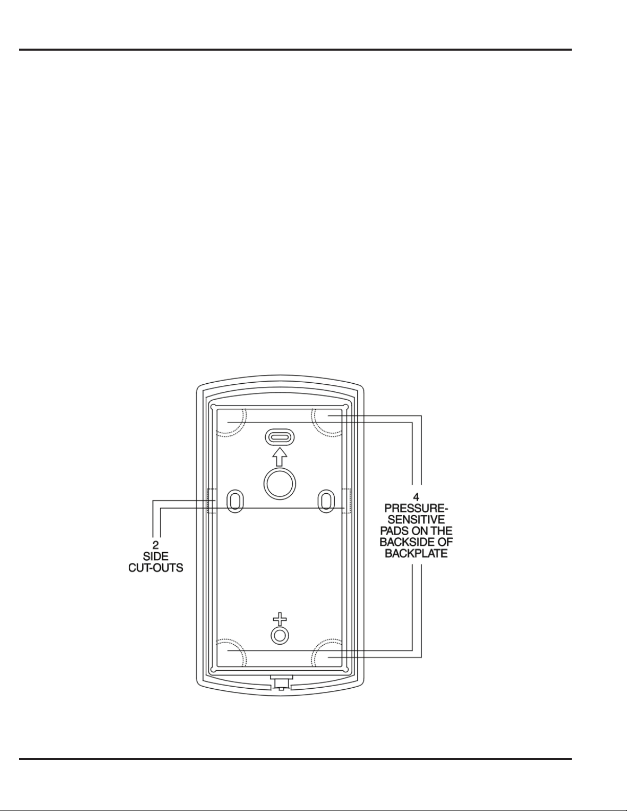
Figure 3 below shows the four supplied pressure-sensitive adhesive pads and the two side cut-outs used for this installation.
In this confi guration, the prox.pad unit is affi xed with the four self-adhesive pads to the glass or the glass window adjacent
to the door being accessed, on the interior side of the glass. One of the two side cut-outs is used to bring the wires out of
the side of the prox.pad case.
A typical glass mounted installation proceeds as follows:
1. Disconnect the back housing from the front keypad/ controller. Remove the tape from the four self-adhesive pads
on the back housing and apply the pads to the four corners of the backplate.
2. Affi x the back housing to the glass door or the glass window adjacent to the door being accessed, on the interior
side of the glass.
3. Determine which of the two side cut-outs on the back housing to use for the wiring and remove that cut-out using
the appropriate cutting tool.
4. Pull the wiring through the selected side cut-out as required.
5. Connect the front keypad/controller to the back housing.
6. Install the tamper screw into the hole at the bottom front of the enclosure using a #6 spanner bit.
Page 8 of 32
Figure 3: Performing a Glass Mounted Installation
Document # 6-055678 X2
Page 9

Prox.pad Installer Guide
Performing a Secure Installation
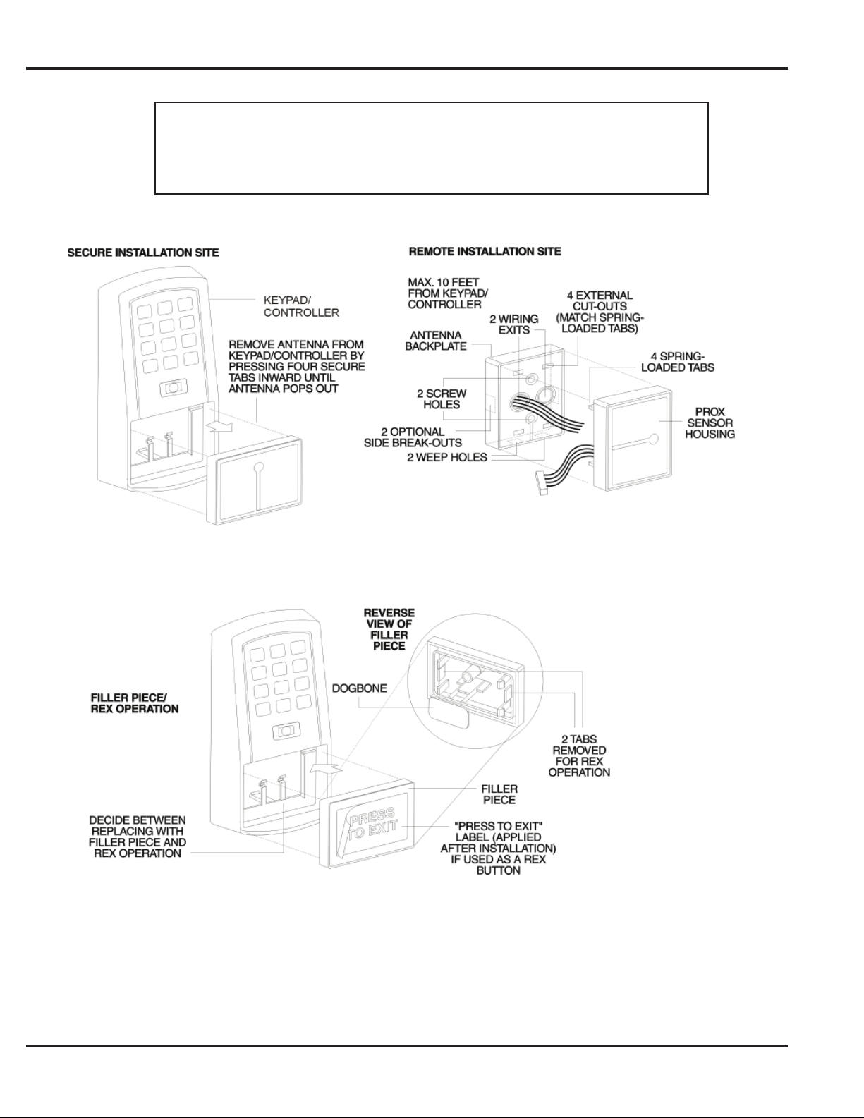
In this confi guration, the prox.pad prox antenna housing is removed from the keypad/controller and located a maximum of
10 feet away. The controller/keypad is located inside the secure area.
1. Remove the antenna housing from the prox.pad keypad/controller as described below:
● Disconnect the backplate of the prox.pad unit from the front keypad/controller.
● When handling the main printed circuit board, to guard against possible static discharges, touch a grounded object
before touching the prox.pad unit. Remove the main printed circuit board by pressing the two spring tabs in the direction
of the arrows as shown in Figure 4 on the next page. Be careful with the wires.
● Pull on the main circuit board and remove the wire harness from P4 from the bottom of the main board. A ribbon cable
now holds the main board to the keypad board. Do not pull this ribbon cable out of its connector! Once the main board is
removed, you can access the interior of the antenna.
● Remove the antenna housing from the keypad/controller by pressing the labeled four secure tabs inward (see Figure 5)
until the antenna housing pops out.
2. Prepare the wiring and extension wiring as follows:
● Cut off the plastic end of the prox.pad antenna housing harness.
● Splice the recommended remote antenna cable Alpha 1294C (22AWG, stranded and shielded), 10-foot maximum
length, to the properly cut antenna cable using standard electrical techniques.
3. Mount the antenna backplate in a vertical orientation and secure it to the wall through the two screw holes using
two provided screws. Ensure that the two weep holes, provided to remove possible moisture, are positioned on the
bottom. The wiring exits in the antenna backplate. (Four external cut-outs on the antenna backplate match the four
spring-loaded tabs on the antenna.)
NOTE: Two side cut-outs are furnished on the antenna backplate for the wiring, if the installation does not permit the
wiring to run through the wall. These must be cut out to be used.
● Once the antenna backplate is mounted properly, align the antenna to the backplate and connect the antenna to the
antenna backplate. The large tab in the center of the antenna assembly must be broken off before being attached to the
antenna backplate.
4. Run the antenna wiring back to the secure keypad/controller and connect it to the main circuit board, using the
10-inch 4-wire harness (red, black, white, and white) that you plug into connector P4 on the controller board.
Connect the red wire of the antenna to the red wire of the P4 harness, etc. Seal the wire holes with silicone.
5. Select Filler or Request to Exit (REX) operation as follows:
● If you elect to use the fi ller piece as a REX switch, return to the keypad/controller and break off two tabs on the fi ller
piece as illustrated in Figure 4. The fi ller piece replaces the antenna on the front of the keypad/controller for secure
installations.
● If the fi ller piece is not to be used as a REX switch, do not remove the two tabs.
● Select “Filler or “REX” operation and affi x the appropriate provided label to the fi ller piece. For Filler operation, no tabs
are broken off the fi ller piece, which merely sits in place of the remotely located antenna, once the main circuit board
and cabling are replaced. For REX operation, break off the labeled tabs, which allows a spring-loaded tab to engage the
REX switch on the main circuit board and open the door.
● Replace the main circuit board into the keypad/controller and pin connector P4 to the main circuit board.
● Connect the front keypad/controller of the unit to the back housing.
● Secure with a hex socket screw using the supplied hex wrench, or secure with a tamper screw (optional tool required).
Document # 6-055678 X2
Page 9 of 32
Page 10
Prox.pad Installer Guide
For the remote antenna wire, use ALPHA 1294C (22AWG) 4-wire, stranded and
shielded cable. The cable shield drain wire must be grounded at the reader end to
P1, pin 4 connection (DC Power Supply Ground).
Page 10 of 32
Figure 4: Performing a Secure Installation
Document # 6-055678 X2
Page 11
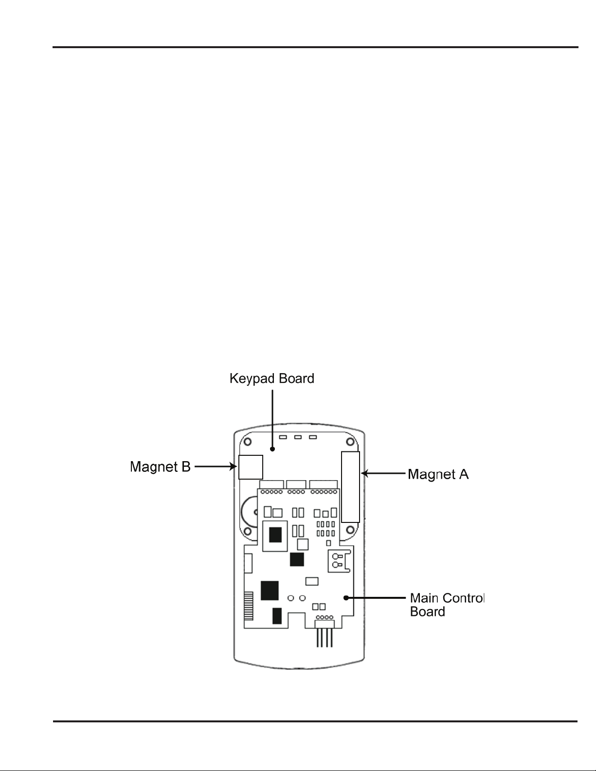
Prox.pad Installer Guide
Installing a Tamper Switch
A tamper switch must be installed in one of the confi gurations described below and connected to an intrusion alarm
system.
Mounting over a metal or plastic single gang J-Box
1. Use an Ademco 945T magnet and reed switch (or equivalent) with foam-backed adhesive tape.
2. Clip the screw mounting tabs from both the magnet and reed switch using pliers or a wire cutter.
3. With the prox.pad base removed, stick the magnet to the Keypad board in location A, using the adhesive tape.
4. Stick the reed switch on the inside of the long side of the J-box in the upper right-hand corner, using thread
adhesive tape. The switch should be fl ush with the edge of the J-box.
Wall mounting
1. Use an Ademco PR-20451 magnet and reed switch (or equivalent).
2. Mount the magnet at location B, using one of the adhesive pads provided.
3. Drill a 3/8 inch hole in the wall behind the magnet location, feed the switch wire through the wall and press the
switch into place.
Document # 6-055678 X2
Figure 5: Tamper Switch Locations
Page 11 of 32
Page 12
Prox.pad Installer Guide
Inserting Circuit Boards
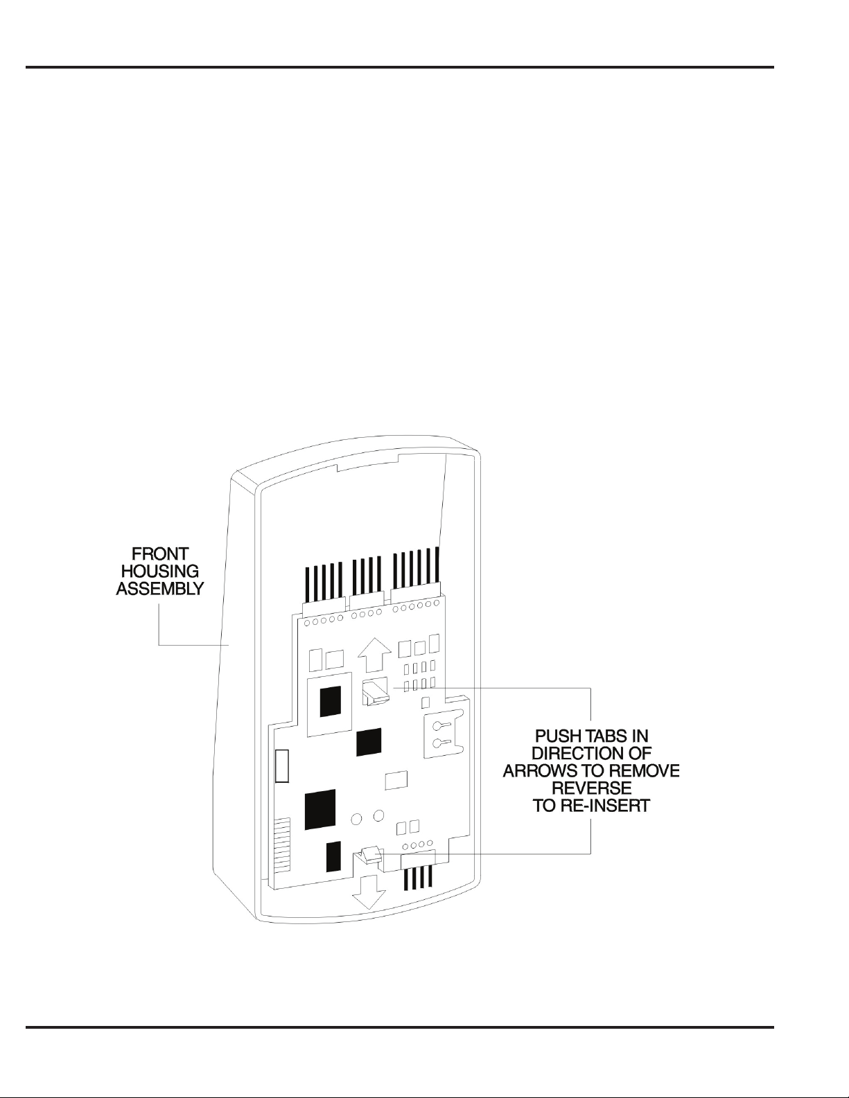
If you must remove or insert the main circuit board from/into the prox.pad controller/keypad, follow the steps below.
1. Disconnect the back housing of the prox.pad unit from the front keypad/controller.
2. When handling the main printed circuit board, to guard against possible static discharges, hold the board
by its edges with one hand and then touch a grounded object before touching the prox.pad unit. Remove
the main printed circuit board by pressing the two spring tabs in the direction of the arrows as shown in Figure 5.
Be careful with the wires.
3. Fold up the main circuit board and remove the P4 connector (a 4-conductor harness) from the bottom of the
board.
4. To re-insert, replace the main circuit board into the keypad/controller and the P4 connector to the main circuit
5. Connect the keypad/controller to the back housing.
Page 12 of 32
Figure 6: Removing/Inserting Printed Circuit Board
Document # 6-055678 X2
Page 13
Prox.pad Installer Guide
Defaulting prox.pad Memory
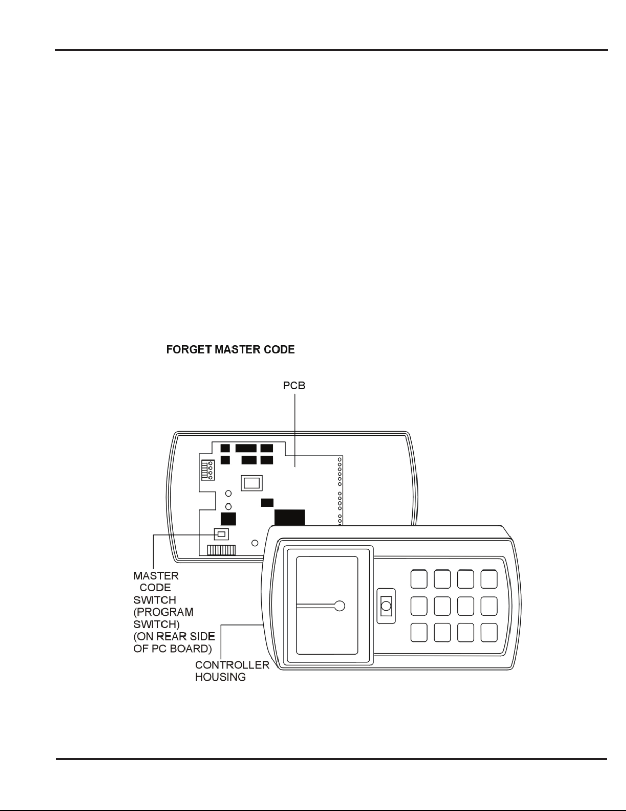
If necessary, the prox.pad main memory can be defaulted (erased). This procedure explains how to do this; see Figure 6
below. You would default the memory, if, for instance, static discharges have corrupted the prox.pad unit, during shipping or
installation. You can also do this if you have simply forgotten the Master Code and you need to enter program mode.
With the power on, remove the case from the prox.pad front controller/keypad to access the main circuit board. (For a visual
reference of the main printed circuit board and the related pin connectors, see Figure 1. The table on page 2 describes these
pins in detail.) (When handling the main printed circuit board, to guard against possible static discharges, touch a grounded
object before touching the prox.pad unit.)
1. With the power on, press and hold the Program button (located on the rear side of the main printed circuit board)
for two seconds and release. The yellow LED fl ashes slowly.
2. Enter the following on the keypad:
46 # 00000 # 00000 # ✱ ✱
The yellow LED fl ickers rapidly for several seconds and then blinks slowly.
3. Once the memory reset is complete press ✱ to exit program mode then re-assemble the unit.
Figure 7: Program Button Location on Main Circuit Board
Document # 6-055678 X2
Page 13 of 32
Page 14
Prox.pad Installer Guide
Standalone Mode Default Settings
The table below lists the default settings for the prox.pad unit as shipped from the factory.
Option Default Setting Option Default Setting
Master Code 1234 Main Relay Time 5 Seconds
Audio Keypress Feedback Enabled Visual Keypress Feedback Enabled
Auxiliary Relay Alarm Shunt Auto-Entry Disabled
Facility Code Access Disabled Forced Door Audio Alert Enabled
Propped Door Audio Alert Enabled Internal REX Switch Disabled
DST Time/Date Format US Daylight Savings Time Enabled
Anti-Passback Enabled Invalid PIN Lockout Disabled
Invalid PIN Lockout Action Timed Lockout 26-Bit Facility Code 1
Anti-Passback Timer 1 Second Invalid PIN Lockout Count 5 Attempts
Invalid PIN Lockout Time 5 Minutes Propped Door Audio Alert 30 Seconds
Forced Door Audio Alert 10 Seconds
Page 14 of 32
Document # 6-055678 X2
Page 15
Prox.pad Installer Guide
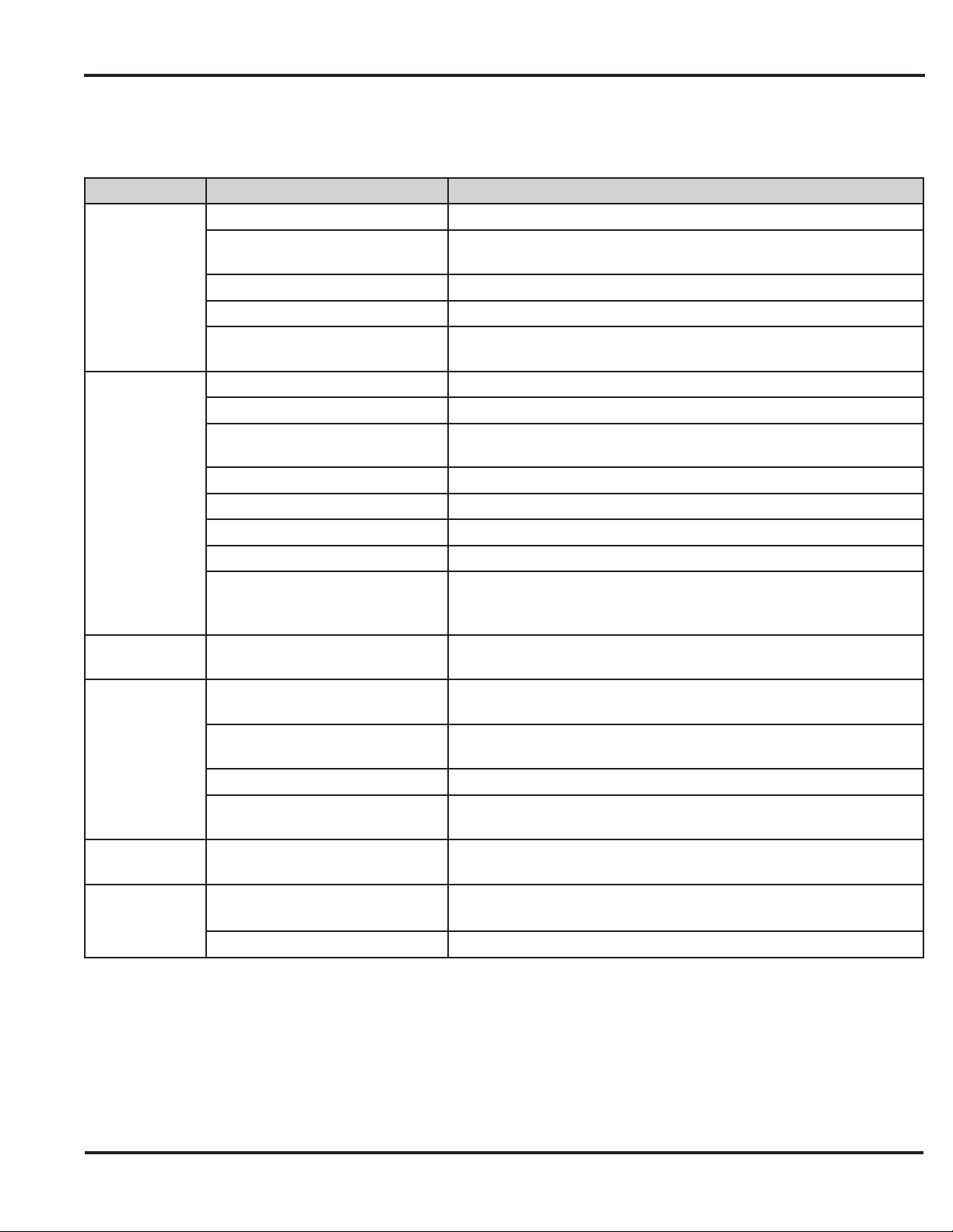
Standalone Mode LED Indicators/Sounder Operations
The table below describes the various LED and Sounder indications used in the prox.pad while operating in standalone mode.
LED/Sounder Visual/Audible Condition Description
Slow blink Unit is in program mode
Verify mode is active (checking that the last two values in
sequence match)
Batch program of cards in progress (command 56); block delete of
users (command 58)
Lock locked, user lockout is active; red LED drops out for 100 ms
every second; a latched lock will override lockout indicator
User lockout is active and lock locked; red LED drops out for 100
ms every second; normal users cannot change the state of the
relay
Power on/reset
EEPROM read error during get system parameters; can be turned
off by running self-test
Propped door is active
Indicates self test
PIN not found, facility code/company ID mismatch and access by
facility mode enabled; incorrect card type (option #20
Yellow LED
Bi-color LED
All LED’s
Sounder
(system)
Sounder (after
PIN)
Sounder (after
card)
Rapid blink
Steady Program error; entry error lockout (no keypress feedback)
Very rapid blink Memory (eeprom) erase is in progress (command 46)
“Pulsing” rapid blink
Steady red Lock is locked
Steady green Lock is energized (timed or latched)
Red Drop out
Green with red blink Lock latched and user lockout is active
Quick double red/green fl ash Prox card read correctly
Alternating red/green Waiting for second PIN or “card and code” user
Solid green with red fl icker Lock toggle is unlocked and user lockout active
Red blink
Rapid red, yellow, green
sequencing
Very quick beep (10 ms) with
yellow LED blink every second
Short beep (100 ms) every 2
seconds
Sounder 1/2 sec on, 1/2 sec off Forced door is active
3 slow beeps (250 ms), followed
by a fourth beep
3 rapid beeps after PIN not found
3 very rapid beeps
1 short beep Valid card access
Document # 6-055678 X2
Page 15 of 32
Page 16
Prox.pad Installer Guide
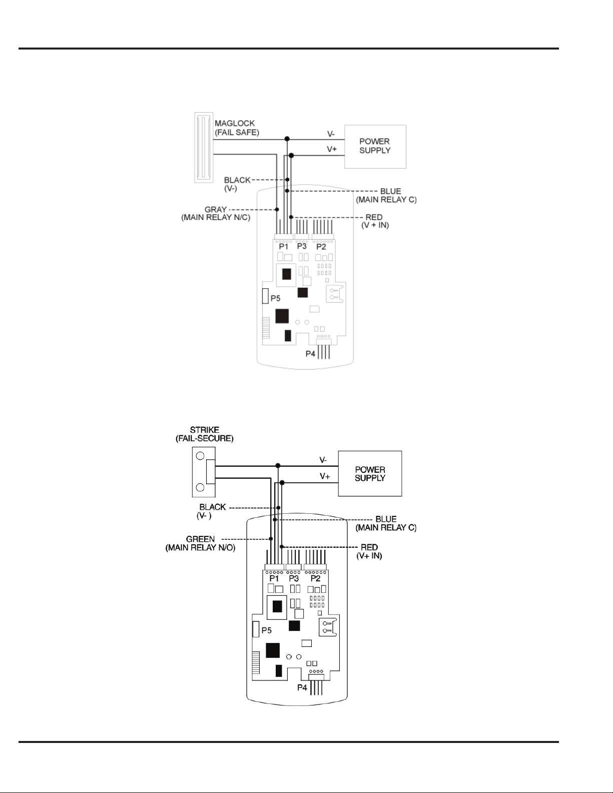
Standalone Mode Wiring
Figure 8: Wiring a Maglock - Fail Safe
Page 16 of 32
Figure 9: Wiring an Electric Strike - Fail Secure
Document # 6-055678 X2
Page 17
Prox.pad Installer Guide
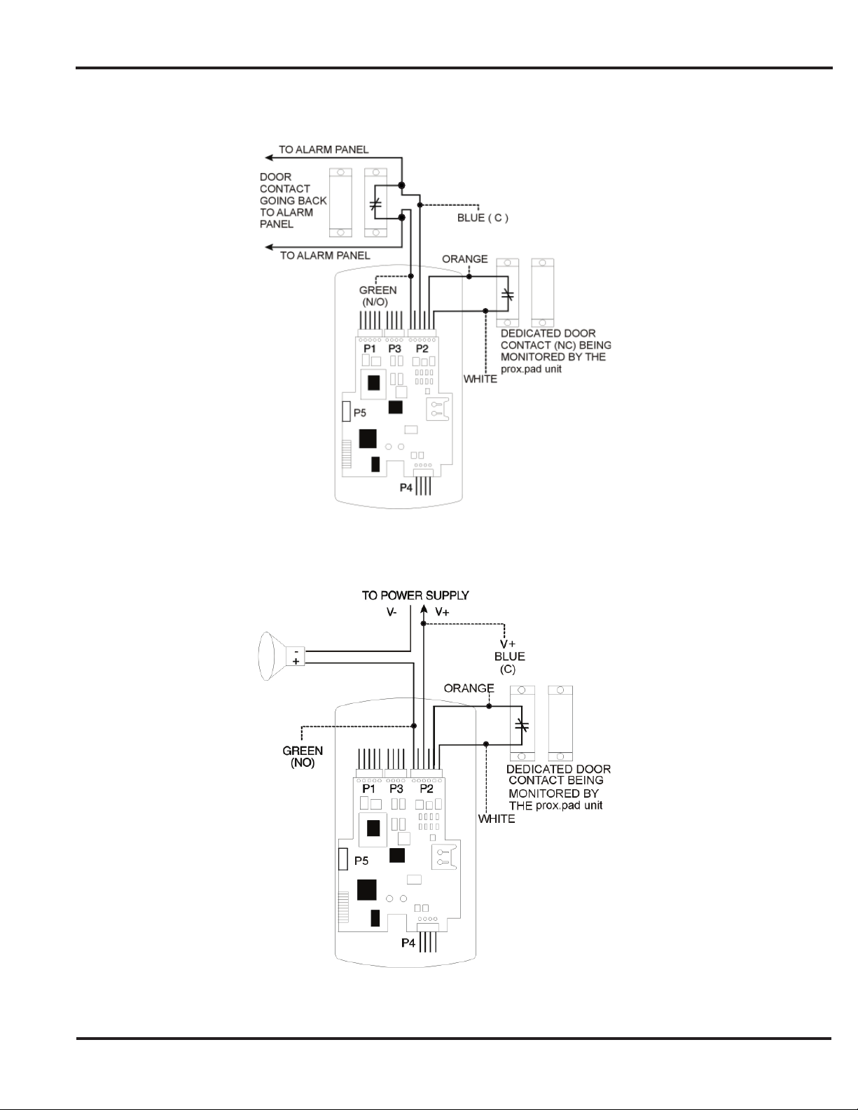
Figure 10: Wiring the Aux Relay for Alarm Shunt
Document # 6-055678 X2
Figure 11: Wiring the Aux Relay for Forced Door
Page 17 of 32
Page 18
Prox.pad Installer Guide
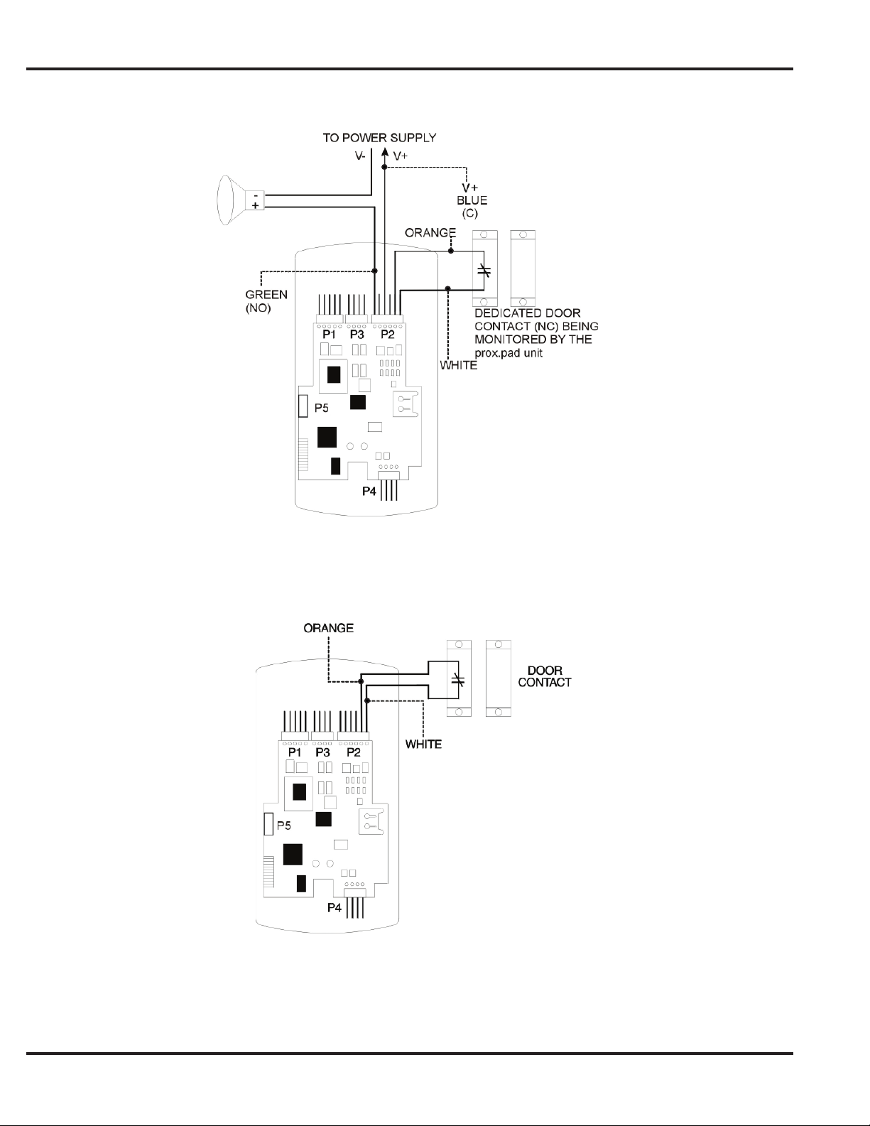
Figure 12: Wiring the Aux Relay For Propped Door
Page 18 of 32
Figure 13: Wiring the Door Contact
Document # 6-055678 X2
Page 19
Prox.pad Installer Guide
Wiring an External REX Switch (Request to Exit)
The prox.pad unit can be wired to monitor a remote switching device, which is intended to be installed on the secure side of
a door. The Request to Exit (REX) switch is a momentary input closure that engages the main relay for the same length of
time for which the main relay is programmed. This feature can be stored in the Transaction Log for viewing.
If you elect to perform a secure installation where the controller is mounted on the secure side of the door, you can use the
fi ller piece as a REX switch. For other installations, a separate REX switch must be purchased.
Other REX devices can be used to include a remote button placed at a receptionist’s desk, a press-to-exit switch on the inside
of a door, or a passive infrared detector, allowing free and convenient egress. The REX feature requires no programming;
simply wire the unit as illustrated in Figure 13. To incorporate this feature, follow the steps below:
1. Turn OFF power to the prox.pad unit, and then unlatch the keypad from the plastic housing.
2. Locate connector P2 on the main circuit board and remove the 2-pin jumper on pins 5 and 6 of connector P2.
3. Plug the 6-conductor harness into connector P2.
4. If you do not wish to install the door contacts per fi gure 13, twist the white wire and the orange wires together;
this is mandatory. If this is not done, the REX input will not function.
NOTE: The door contact MUST be closed for the REX feature to work properly.
NOTE: CONNECTING DOOR LOOP INPUT - Before powering up the prox.pad unit, connect the Door Loop input to
the "Loop Common." This prevents "Forced Door" or "Propped Door" conditions from developing upon power-up.
Document # 6-055678 X2
Figure 14: Wiring an External REX Switch
Page 19 of 32
Page 20
Prox.pad Installer Guide
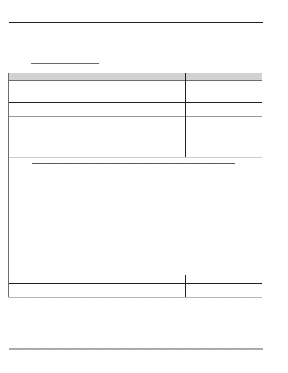
Standalone Mode Program Commands
If you need to change any of the program default values or wish to add functions, fi rst enter program mode and then enter
the desired program command. Defaults are in bold.
Note: The master code must be changed prior to performing any programming on the prox.pad unit. When programming
users, the term user location refers to the place in the units memory that the user is stored.
Action Desired
Enter Program Mode
Change master code
Set main relay time
Set AUX relay output
Delete Users
Set/clear standard option
Option Set Clear
0 — Audio Keypress Feedback 1 = Enabled 0 = Disabled
1 — Visual Keypress Feedback 1 = Enabled 0 = Disabled
2 — Auto Entry 0 = Disabled 1 = Enabled
3 — Operating Mode 0 = Standalone 1 = Front End
4 — Facility Code Access 0 = Disabled 1 = Enabled
5 — Forced Door Audio Alert 0 = Disabled 1 = Enabled
Press Details
99 # (Master Code) ✱
1 # (new code) ✱ (repeat code) ✱
Ex: 1 # 4321 ✱ 4321 ✱
11 # tt # 0 # ✱ ✱
15 # output # 0 # ✱ ✱
user location # ✱ ✱
30 # option # s/c # ✱ ✱
Yellow LED blinks slowly
Enter new code
tt=1-99 seconds (default =
5 seconds)
0=disabled
1=shunt (default)
2=forced door
3=propped door
See Chart below
6 — Propped Door Audio Alert 0 = Disabled 1 = Enabled
7 — Internal REX Switch 0 = Disabled 1 = Enabled
8 — Daylight Savings Time Format 0 = US 1 = European
13 — Daylight Savings Time 0 = Disabled 1 = Enabled
14 — Prox Card Anti-Passback Select 0 = Disabled 1 = Enabled
18 — Invalid PIN Lockout Select 0 = Disabled 1 = Enabled
19 — Invalid PIN Lockout Action 0 = Timed Lockout 1 = Forced Door Output
Print User List
Print User List
(From Certain User Location)
Page 20 of 32
25 # 0 # 0 # ✱ ✱
25 # 0 # start user # ✱ ✱
Document # 6-055678 X2
Page 21
Prox.pad Installer Guide
Action Desired
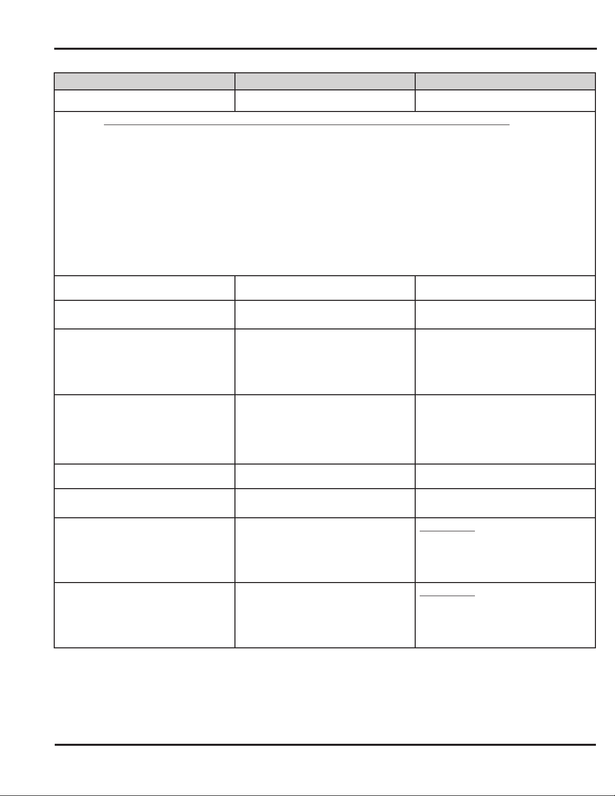
Change Platform Parameters
Parameter Value
2 — 26 Bit Facility Code 0 — 255; (Default = 1)
Note: IEI Cards are Facility Code 11
3 — Process Card Time 2 — 240; 1/4 sec. Increments
(Defaults to 4 = 1 sec.)
4 — Invalid PIN Lockout Attempts 1 — 50 (Default = 5)
5 — Invalid PIN Lockout Duration 1 — 255; 5 sec. increments;)
(Defaults to 60 = 5 Minutes)
Set System Time
Set System Date
Set Propped Door Time
Set Forced Door Time
Press Details
32 # parameter # value # ✱ ✱
41 # hhmm # 0 # ✱ ✱
42 # mmddyy # dow # ✱ ✱
44 # ttt # 0 # ✱ ✱
45 # ttt # 0 # ✱ ✱
See Chart Below
hhmm=hour/minute (24 Hour Format)
mmddyy=month, date, year; dow=day
of week, 1=Sunday
ttt=propped door time, to nearest
10’s seconds, entered as 30-990;
(default=30 secs)
(this sets the time for both Aux Relay
and local sounder)
ttt=propped door time, to nearest
10’s seconds, entered as 30-990;
(default=10 secs)
(this sets the time for both Aux Relay
and local sounder)
Reset System Defaults Only
Delete Entire Memory and Reset
System Defaults
Program User — Code Only
Program User — Code AND Card By
Presenting Card
Document # 6-055678 X2
40 # 00000 # 00000 # ✱ ✱
46 # 00000 # 00000 # ✱ ✱
50 # user type # user location #
code ✱ repeat code ✱
50 # user type # user location #
code ✱ repeat code ✱ ✱ <present
card>
Does not delete users
Deletes all memory including users
User Types:
0-Toggle/latch lock
1-Normal access
2-Log Dump
3-Lockout
User Types:
0-Toggle/latch lock
1-Normal access
2-Log Dump
3-Lockout
Page 21 of 32
Page 22
Prox.pad Installer Guide
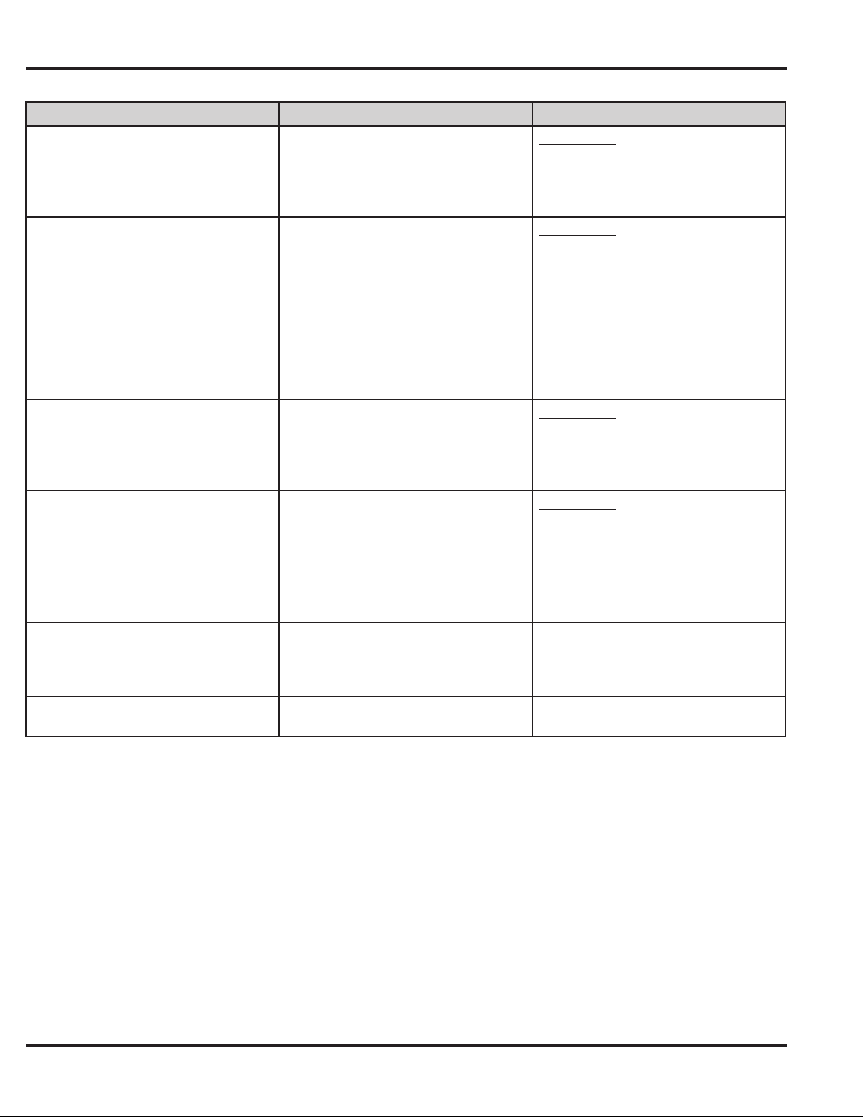
Action Desired
Program User - Card Only
By Presenting Card
Program User –Card Only
Without Presenting Card
Program User – Code OR Card
By Presenting Card
Program Consecutive Users – Card
Only
By Presenting Cards
Program Consecutive Users – Card
Only
Without Presenting Cards
Delete Block of Consecutive Users
Press Details
User Types:
50 # user type # user location # ✱ ✱
<present card>
51 # user type # user location #
card PIN ✱ card PIN ✱
52 # user type # user location#
code ✱ repeat code ✱ <present
card>
53 # user type # start user location
# ✱ ✱
<present card1>
<presentcard2>
<present card3>...
56 # total count # user location #
card PIN ✱ card pin ✱
58 # star user # star user # number
of users ✱ number of users ✱
0-Toggle/latch lock
1-Normal access
2-Log Dump
3-Lockout
User Types:
0-Toggle/latch lock
1-Normal access
2-Log Dump
3-Lockout
For 26-bit Cards only.
The card PIN is the fi rst 5 digits on
the card (facility code must be entered
fi rst; see 32 # 2 # command)
User Types:
0-Toggle/latch lock
1-Normal access
2-Log Dump
3-Lockout
User Types:
0-Toggle/latch lock
1-Normal access
2-Log Dump
3-Lockout
Present cards one after another.
“Total count” = total number of cards to
be entered; card PIN appears on the
card; a facility code must be entered
fi rst (see command 32, option #2)
Page 22 of 32
Document # 6-055678 X2
Page 23

Prox.pad Installer Guide
PAGE LEFT BLANK INTENTIONALLY
Document # 6-055678 X2
Page 23 of 32
Page 24
Prox.pad Installer Guide
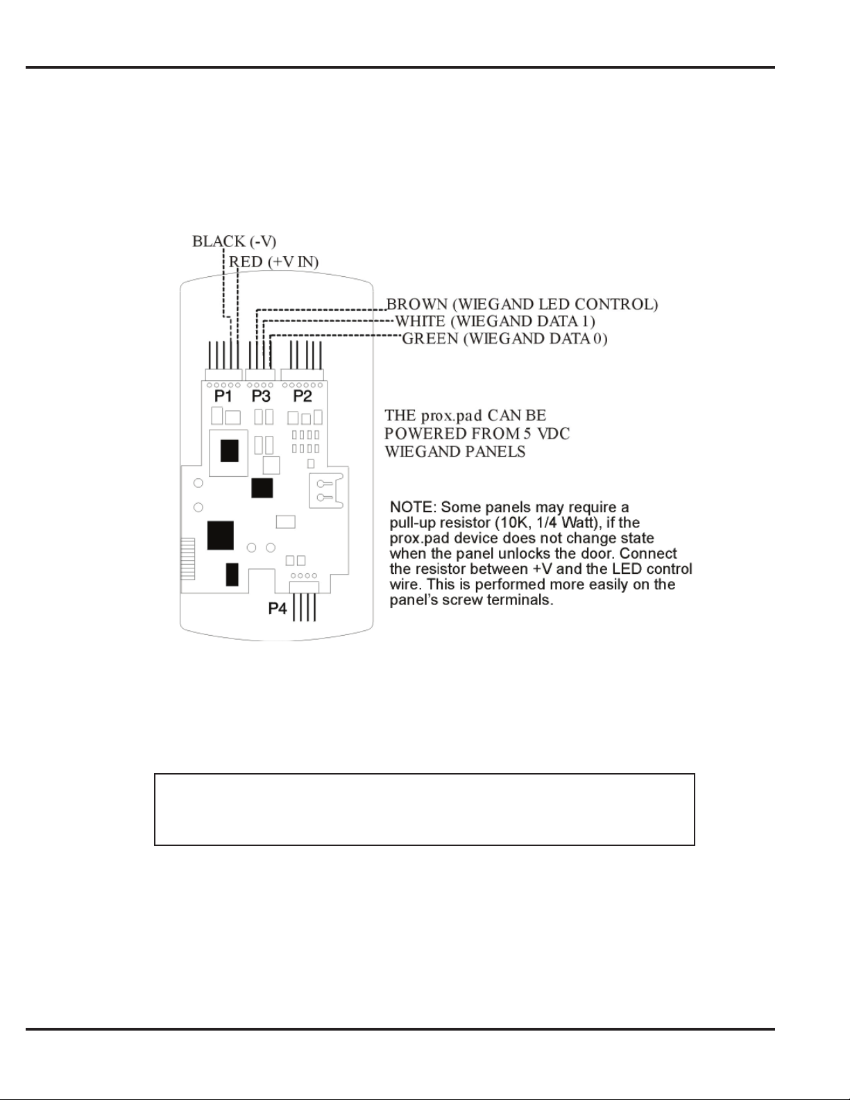
Wiring a Wiegand Front End
The following section shows how to wire the prox.pad to a Wiegand control panel. If you require further information on the
Wiegand panel connections please refer to the instructions that came with the panel.
Page 24 of 32
Figure 15: Connecting the prox.pad to a Wiegand Panel
Use ALPHA 1295C (22AWG) 4 - wire, stranded and shielded cable. The cable shield
drain wire must be grounded at the reader end to P1, pin 4 connection (DC Power
Supply Ground).
Document # 6-055678 X2
Page 25
Prox.pad Installer Guide
Wiegand Mode LED/Sounder States
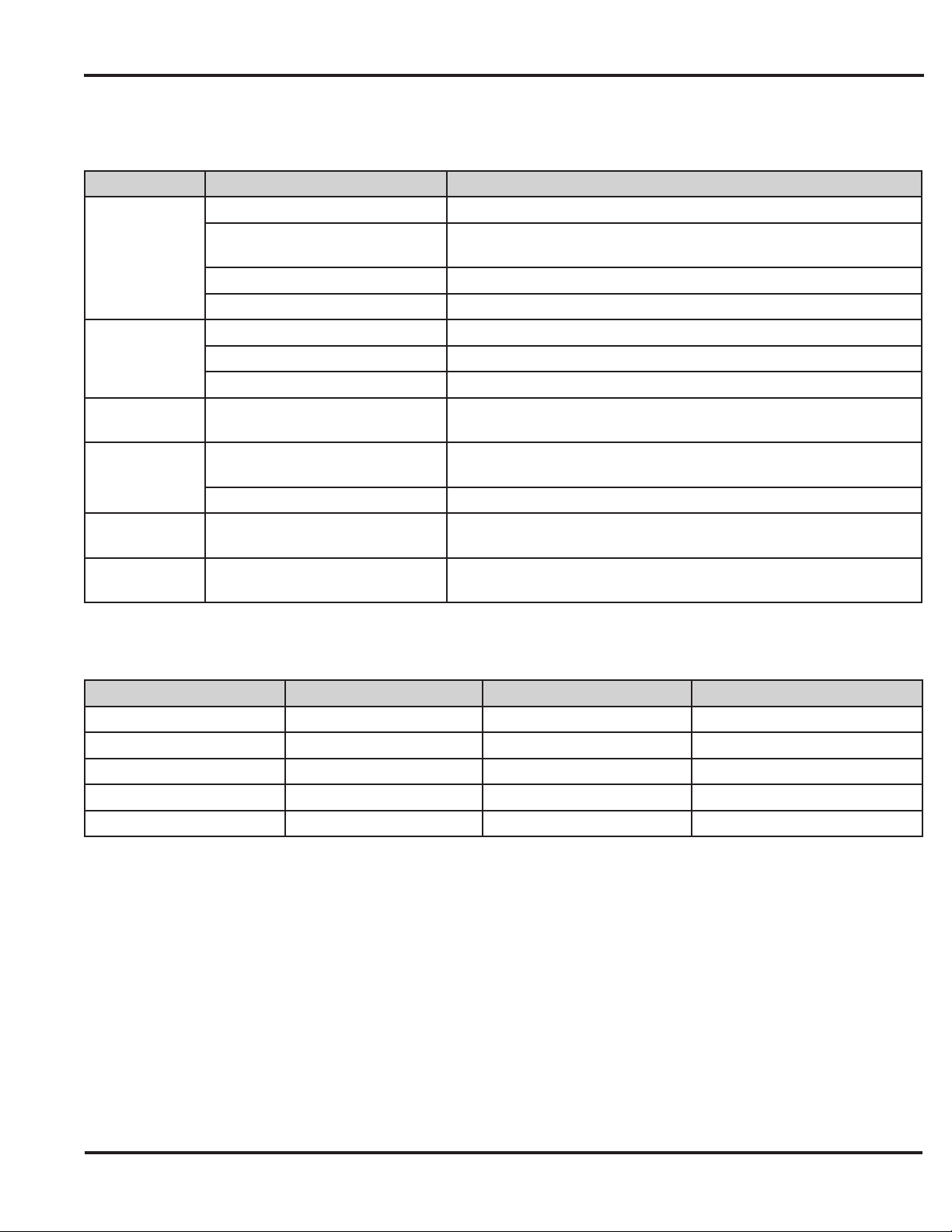
The table below describes the various LED and Sounder indications used in the prox.pad while in Wiegand Front End Mode.
LED/Sounder Visual/Audible Condition Description
Slow blink Unit is in program mode
Verify mode is active (checking that the last two values in
sequence match)
Power on/reset
EEPROM read error during get system parameters; can be turned
off by running self-test
Value entered too big, cannot be represented in 16 bits (Wiegand
mode)
Yellow LED
Bi-Color LED
All LED's
Sounder
(system)
Sounder (after
PIN)
Sounder (after
card
Rapid blink
Steady Program error; entry error lockout (no keypress feedback)
Very rapid blink Memory (eeprom) erase is in progress (command 46)
Steady red Lock is locked
Steady green Lock is energized (timed or latched)
Quick double red/green fl ash Prox card read correctly
Rapid red/yellow, green
sequencing
Very quick beep (10 ms) with
yellow LED blink every second
3 slow beeps (250 ms) Indicates self-test
Single long beep
1 short beep Valid card access
Wiegand Front End Mode Default Settings
Option Default Setting Option Default Setting
Master Code 1234 Audio Keypress Feedback Enabled
Visual Keypress Feedback Enabled Auto-Entry Disabled
Wiegand Red LED Enabled Red LED Active State Low
Wiegand Green LED Enabled Green LED Active State High
Pulse Width 8 = 160µS Inter-pulse Spacing 32 = 640µS
Document # 6-055678 X2
Page 25 of 32
Page 26
Prox.pad Installer Guide
Wiegand Programming Commands
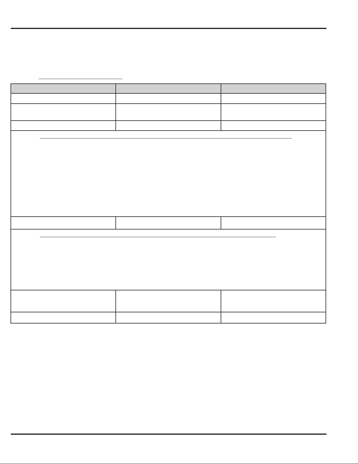
If you need to change any of the program default values or wish to add functions, fi rst enter program mode and then enter
the desired program command. Defaults are in bold.
Note: The master code must be changed prior to performing any programming on the prox.pad unit.
Action Desired
Enter Program Mode
Change master code
Set/clear standard option
Option Set Clear
0 — Audio Keypress Feedback 1 = Enabled 0 = Disabled
1 — Visual Keypress Feedback 1 = Enabled 0 = Disabled
2 — Auto Entry 0 = Disabled 1 = Enabled
3 — Operating Mode 0 = Standalone 1 = Front End
9 — Wiegand Red LED Enable 0 = Disabled 1 = Enabled
10 — Wiegand Red LED Active State 0 = Low 1 = High
11 — Wiegand Green LED Enable 0 = Disabled 1 = Enabled
12 — Wiegand Green LED Active State 0 = Low 1 = High
15 — Front End Mode Select 0 = Wiegand Front End 1 = Secured Series Front End
Change Platform Parameters
Parameter Value
0 — Wiegand Pulse Width 1 — 255; 20µS increments;
(Defaults to 8 = 160µS)
Press Details
99 # (Master Code) ✱
1 # (new code) ✱ (repeat code) ✱
Ex: 1 # 4321 ✱ 4321 ✱
30 # option # s/c # ✱ ✱
32 # parameter # value # ✱ ✱
Yellow LED blinks slowly
Enter new code
See Chart Below
See Chart Below
1 — Wiegand Interpulse Spacing 1 — 255; 20µS increments;
(Defaults to 32 = 640µS)
Delete Entire Memory and Reset
System Defaults
To exit Program mode
46 # 00000 # 00000 # ✱ ✱
Press ✱
Yellow stops fl ashing
Page 26 of 32
Document # 6-055678 X2
Page 27
Prox.pad Installer Guide
Wiring the Secured Series Front End
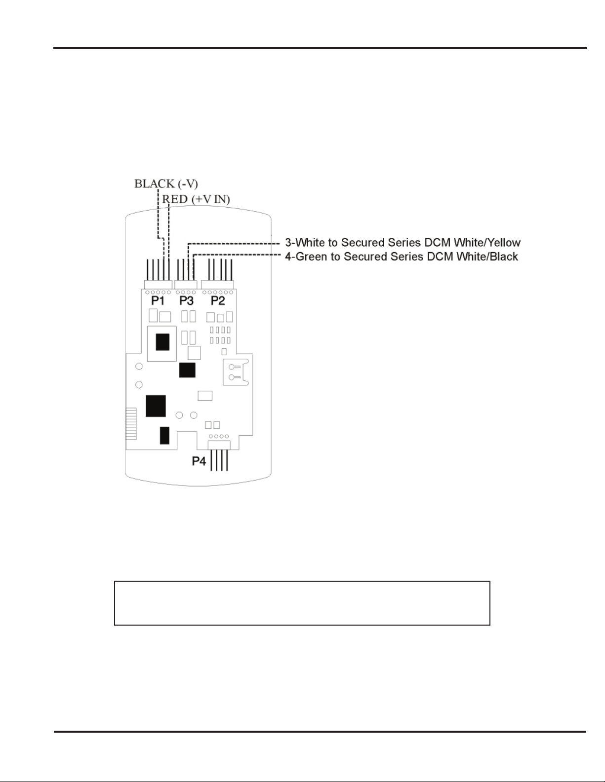
You can connect the prox.pad as a front end to an IEI Secured Series Door Control Module by following the diagram
below. Using connector P3 on the prox.pad, connect the white wire to the Secured Series DCM’s white/yellow wire or
the white/yellow terminal strip and connect the green wire to the white/black wire or white/black terminal strip on the
Secured Series DCM.
Figure 16: Connecting the prox.pad to a Secured Series DCM
Use ALPHA 1295c (22AWG) 4-wire, stranded and shielded cable. The cable shield
drain wire must be grounded at the reader end to P1, pin 4 connection (DC Power
Document # 6-055678 X2
Supply Ground)
Page 27 of 32
Page 28
Prox.pad Installer Guide
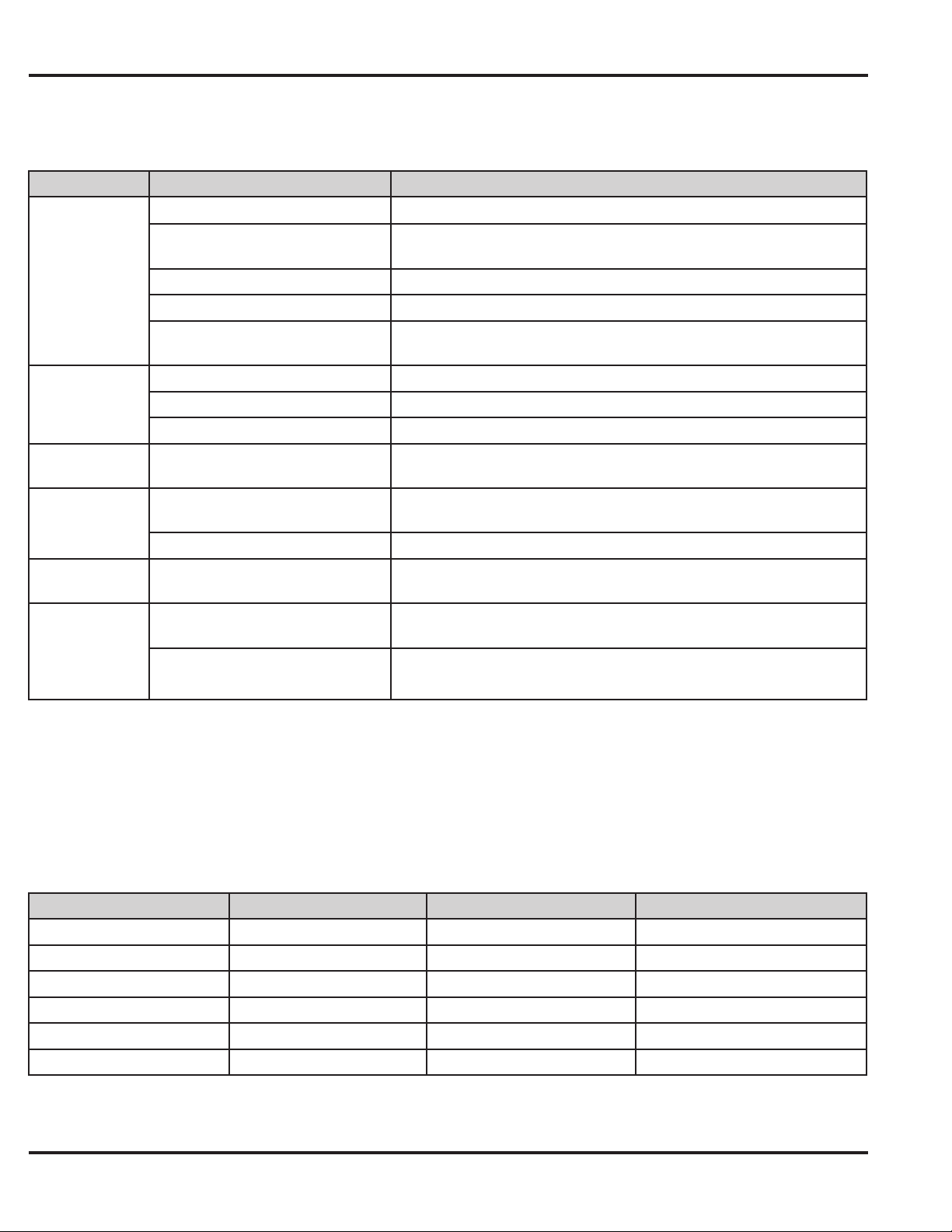
Secured Series Front End Mode LED Indicators/Sounder
LED/Sounder Visual/Audible Condition Description
Slow blink Unit is in program mode
Yellow LED
Bi-color LED
All LED's
Sounder
(system)
Sounder (after
PIN)
Sounder (after
card)
Rapid blink
Steady Program error; entry error lockout (no keypress feedback)
Very rapid blink Memory (eeprom) erase is in progress (command 46)
“Pulsing” rapid blink
Steady red Lock is locked
Steady green Lock is energized (timed or latched)
Quick double red/green fl ash Prox card read correctly
Rapid red, yellow, green
sequencing
Very quick beep (10 ms) with
yellow LED blink every second
3 slow beeps (250 ms) Indicates self test
3 rapid beeps after PIN not found
3 very rapid beeps
1 short beep Valid card access
Verify mode is active (checking that the last two values in sequence
match)
Batch program of cards in progress (command 56); block delete of
users (command 58)
Power on/reset
EEPROM read error during get system parameters; can be turned
off by running self-test
PIN not found, facility code/company ID mismatch and access by
facility mode enabled; incorrect card type (option #20)
Secured Series Front End Mode Default Settings
Option Default Setting Option Default Setting
Master Code 1234 Audio Keypress Feedback Enabled
Visual Keypress Feedback Enabled Auto-Entry Disabled
Anti-Passback Enabled Reader In/Out Select In
Keypad In/Out Select In Prox Card Type 26-bit
Facility Match Required Disabled Facility Code 1
Corporate 1000 ID 4095
Page 28 of 32
Document # 6-055678 X2
Page 29
Prox.pad Installer Guide
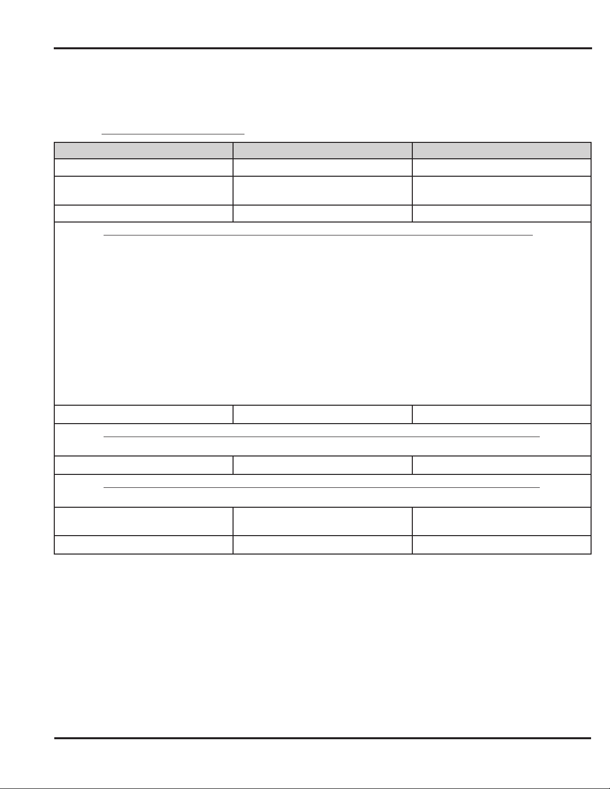
Secured Series Programming Commands
If you need to change any of the program default values or wish to add functions, fi rst enter program mode and then enter
the desired program command. Defaults are in bold.
Note: The master code must be changed prior to performing any programming on the prox.pad unit.
Action Desired
Enter Program Mode
Change master code
Set/clear standard option
Option Set Clear
0 — Audio Keypress Feedback 1 = Enabled 0 = Disabled
1 — Visual Keypress Feedback 1 = Enabled 0 = Disabled
2 — Auto Entry 0 = Disabled 1 = Enabled
3 — Operating Mode 0 = Standalone 1 = Front End
14 — Prox Card Anti-Passback Select 0 = Disabled 1 = Enabled
15 — Front End Mode Select 0 = Wiegand Front End 1 = Secured Series Front End
16 — Keypad In/Out Select 0 = In (keypad outside) 1 = Out (keypad inside)
17— Reader In/Out Select 0 = In (reader outside) 1 = Out (reader inside)
20— Prox Card Type Select 0 = 26 Bit 1 = Corporate 1000
21 — Facility Match Required 0 = Disabled 1 = Enabled
Change Platform Parameters
Parameter Value
2 — 26 Bit Facility Code 0 — 255 (default=1)
Enter Corporate 1000 Company ID
Press Details
99 # (Master Code) ✱
1 # (new code) ✱ (repeat code) ✱
Ex: 1 # 4321 ✱ 4321 ✱
30 # option # s/c # ✱ ✱
32 # parameter # value # ✱ ✱
35 # parameter # value # ✱ ✱
Yellow LED blinks slowly
Enter new code
See Chart Below
See Chart Below
See Chart Below
Parameter Value
0 — Corporate 1000 Company ID 0 — 4095 (default = 4095)
Delete Entire Memory and Reset
System Defaults
To exit Program mode
Document # 6-055678 X2
46 # 00000 # 00000 # ✱ ✱
Press ✱
Yellow stops fl ashing
Page 29 of 32
Page 30

Prox.pad Installer Guide
Technical Support
Service Company: Before calling Linear LLC for installation assistance, refer to Chapter 5, Troubleshoot-
ing. This chapter includes a list of common system problems, possible causes, and corrective actions
plus easy-to-use diagnostic fl ow charts. To contact Linear LLC Technical Services department, call
1 800-421-1587 between 5:00 a.m. and 4:30 p.m. (Pacifi c Time), Monday through Friday. You can also
download an electronic version of this manual from this site.
End User:
Please contact your service company.
Warranty
Linear LLC warrants its products to be free from defects in material and workmanship, when they have been installed
in accordance with the manufacturer’s instructions, and have not been modifi ed or tampered with. Linear LLC does not
assume any responsibility for damage or injury to person or property due to improper care, storage handling, abuse,
misuse, normal wear and tear, or an act of God.
Linear LLC’s sole responsibility is limited to the repair (at Linear LLC’s option) or the replacement of the defective product
or part when sent to Linear LLC’s facility (freight and insurance charges prepaid), after obtaining Linear LLC’s Return
Merchandise Authorization. Linear LLC will not be liable to the purchaser or any one else for incidental or consequential
damages arising from any defect in, or malfunction of, its products.
This warranty shall expire two years after shipping date for prox.pad Keypads. Except as stated above,Linear LLC makes
no warranties, either expressed or implied, as to any matter whatsoever, including, without limitation to, the condition of
its products, their merchantability, or fi tness for any particular application.
Page 30 of 32
Document # 6-055678 X2
Page 31

Prox.pad Installer Guide
PAGE LEFT BLANK INTENTIONALLY
Document # 6-055678 X2
Page 31 of 32
Page 32

Prox.pad Installer Guide
Now Part of
IEI Document Number
6055678 Rev 2.2
Page 32 of 32
USA & Canada (800) 421-1587 & (800) 392-0123
(760) 438-7000 - Toll Free FAX (800) 468-1340
www.linearcorp.com
Document # 6-055678 X2
 Loading...