

Page 1
detcon inc.
™
Detcon MicroSafe
IR-540/541 Carbon Dioxide Sensor (0-5%CO2)
IR542 Carbon Dioxide Sensor (10%-100%)
Operator’s Installation & Instruction Manual
November 28, 2007 • Document #2379 • Version 1.5
CAUTION:
Before operating the Model IR-540/IR-541/IR-542 sensor, read this manual thoroughly and verify that the
configuration of default factory settings are appropriate and correct for your application.
Page 2

Table of Contents
3.0 Description
3.1 Principle of Operation
3.2 Application
3.3 Specifications
3.4 Operating Software
3.5 Installation
3.6 Start-up
3.7 Calibration
3.8 Status of Programming, Calibration Level, and Sensor Life
3.9 Program Features
3.10 Display Contrast Adjust
3.11 Optical Sensor Replacement
3.12 Trouble Shooting Guide
3.13 Spare Parts List
3.14 Warranty
3.15 Service Policy
3.16 Software Flow Chart
Detcon Model IR-540/IR-542 Carbon Dioxide Sensor PG.2
Page 3
3.0 DESCRIPTION
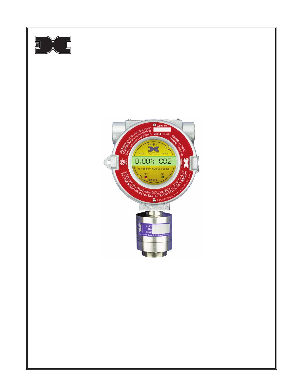
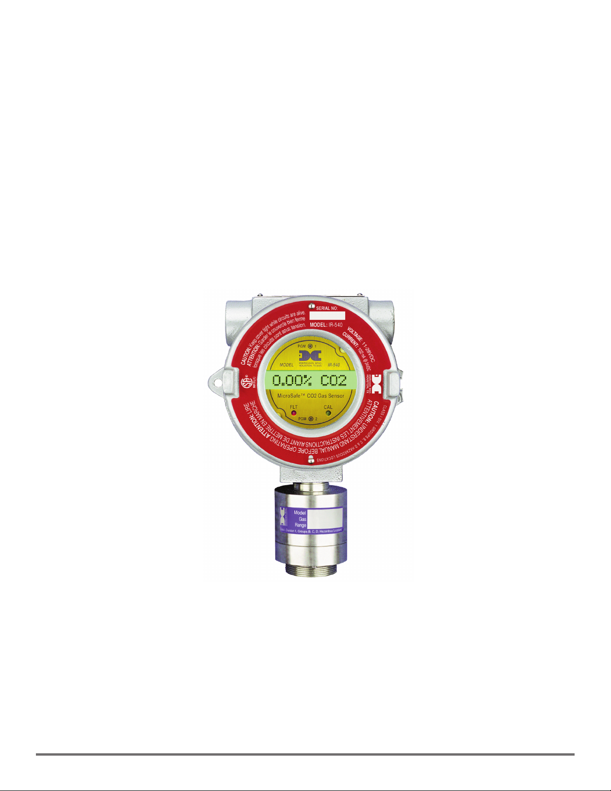
Detcon MicroSafe™ Model IR-540/IR-541/IR-542, carbon dioxide gas sensors are non-intrusive “Smart” sensors
designed to detect and monitor CO2gas in air over the 0-5% range. The Detcon MicroSafe™ Model IR-542 CO2
gas sensor measures in the 10-100% Range. One of the primary features of the sensor is its method of automatic
calibration which guides the user through each step via instructions displayed on the backlit LCD. The sensor output is a standard 4-20 mA signal. The microprocessor supervised electronics are packaged as a plug-in module that
mates to a standard connector board. Both are housed in an explosion proof condulet that includes a glass lens. A
16 character alpha/numeric indicator is used to display sensor readings as well as the sensor’s menu driven features
via a hand-held programming magnet.
The sensor technology is a field proven “plug-in replaceable” non-dispersive infrared (NDIR) optical type. NDIR
optical sensors show an excellent response to CO2. The NDIR type sensor is characteristically stable for both span
and zero and is capable of providing reliable performance with low maintenance requirements for periods approaching 5 years in most industrial environments.
Typical ranges of detection are 0-0.30%, 0-0.50%, 0-1.00%, 0-2.00%, 0-3.00% and 0-5% with the IR540/IR-541.
Typical Ranges with the IR542 are 0-10%, 0-25%, 0-50%, 0-100%. Other ranges may be accommodated and all
ranges are covered by this manual. To determine the range of detection, refer to the instructions found in section
3.8.
3.0.1 Non-dispersive Infrared (NDIR) Optical Sensor
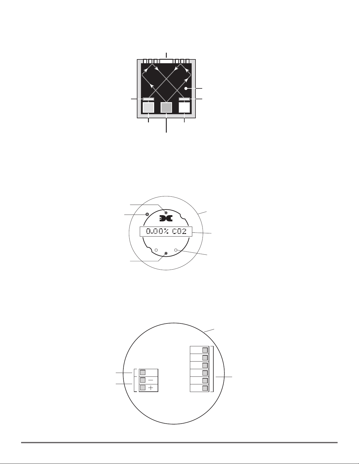
The Detcon NDIR sensor is designed as a miniature single piece “plug-in replaceable” component, which can easily be
changed out in the field. The NDIR sensor consists of an infrared lamp source, two pyroelectric detectors, and an
optical gas sample cavity. The lamp source produces infrared radiation which interacts with CO2as it travels through
the optical gas sample cavity. The infrared radiation contacts each of two pyroelectric detectors at the completion of
the optical path. The “active” pyroelectric detector is covered by a f ilter specific to the part of the IR spectrum where
CO2absorbs light. The “reference” pyroelectric detector is covered by a filter specific to the non-absorbing part of the
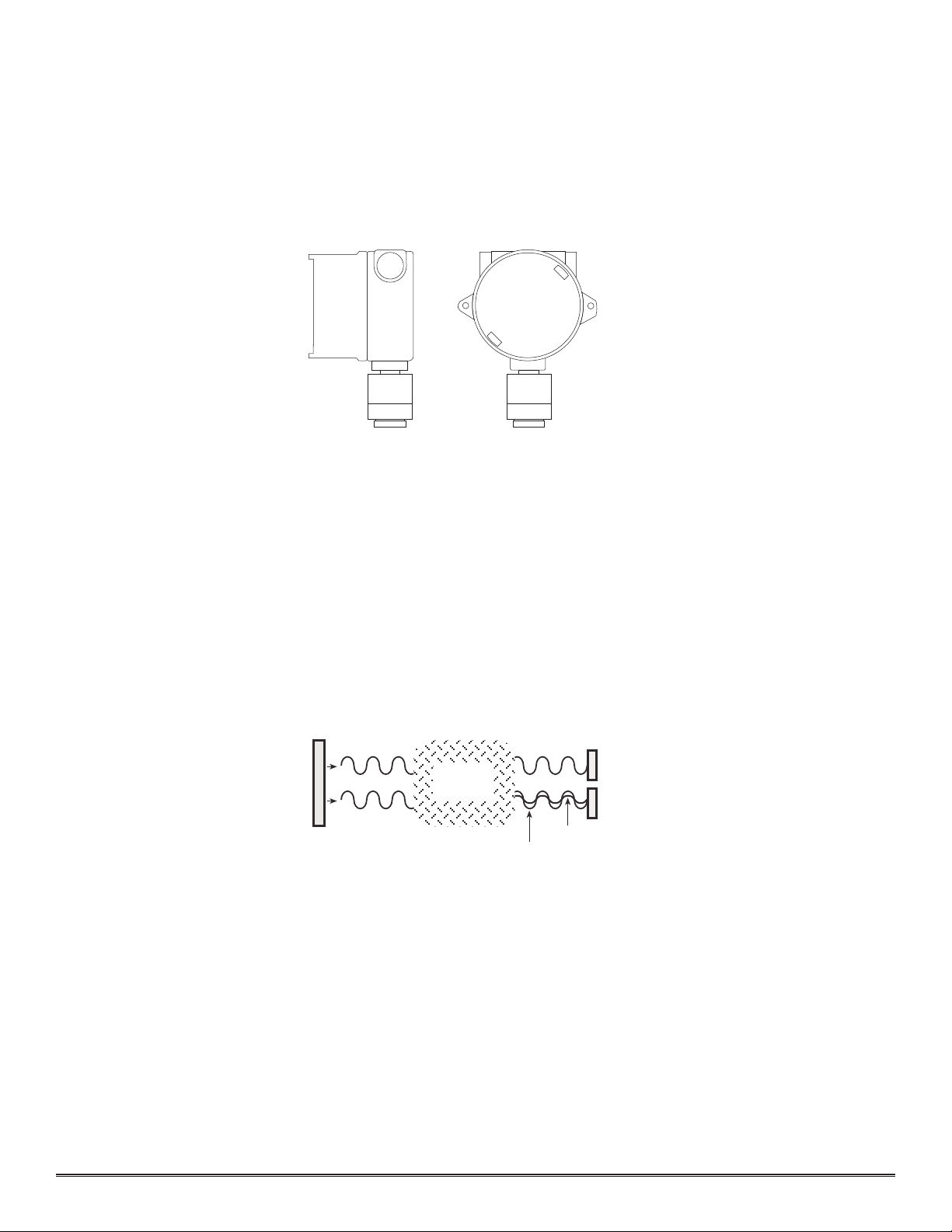
IR spectrum. When CO2is present, it absorbs IR radiation and the signal output from the “active” pyroelectric detector decreases accordingly while the “reference” detector output remains unchanged. The ratio of the “active” and “reference” detector outputs is then used to compute CO2concentration.
Detcon Model IR-540/IR-542 Carbon Dioxide Sensor PG.3
Page 4
3.0.2 Microprocessor Control Circuit
detcon inc.
Program Switch #2
FLT CAL
MicroSafe™ CO2 Gas Sensor
HOUS TON, TEX AS
PGM 2
PGM 1
MODEL IR-540
CONTRAST
Fault & Cal LEDs
Program Switch #1
Menu Driven Display
Plug-in Microprocessor Control Circuit
Display Contrast Adjust
Porous Membrane
Optical Filter
Active Detector
Lamp
Reference Detector
Optical Sample Gas Chamber
Optical Filter
CO
2
CO
2
BLU
YEL
BLK
WHT
mA
VDC Power In
4-20 mA Output
BRN
RED
Sensor
Base Connector Board
The control circuit is microprocessor based and is packaged as a plug-in field replaceable module, facilitating easy
replacement and minimum down time. Circuit functions include a basic sensor pre-amplifier, sensor temperature
measurement, on-board power supplies, microprocessor, back-lit alpha numeric display, fault and calibration status
LED indicators, magnetic programming switches, and a linear 4-20 mA DC output.
3.0.3 Base Connector Board
The base connector board is mounted in the explosion proof enclosure and includes: the mating connector for the
control circuit, reverse input and secondary transient suppression, input filter, and lugless terminals for field wiring.
Detcon Model IR-540/IR-542 Carbon Dioxide Sensor PG.4
Page 5
3.0.4 Explosion Proof Enclosure
IR Lamp Source
Reference Detector Output
Active Detector Output
CO2 Not Present
CO2 Present
Principle of Operation
Sample
Gas
The sensors are packaged in a cast metal explosion proof enclosure. The enclosure is fitted with a threaded cover
that has a glass lens window. Magnetic program switches located behind the transmitter module face plate are activated through the lens window via a hand-held magnetic programming tool allowing non-intrusive operator interface with the sensor. Calibration can be accomplished without removing the cover or declassifying the area.
Electrical classification is Class I; Groups B, C, D; Div. 1.
3.1 PRINCIPLE OF OPERATION
The CO2diffuses through a sintered stainless steel f lame arrestor and into the volume of the sample gas optical
cavity. A lamp source provides a cyclical IR radiation source which travels through the optical gas sample cavity and
terminates at two pyroelectric detectors. The “active” and “reference” pyroelectric detectors each give an output
which measures the intensity of the radiation contacting their surface. The “active” pyroelectric detector is covered
by an optical filter specific to the part of the IR spectrum where CO2absorbs light. The “reference” pyroelectric
detector is covered by a filter specific to the non-absorbing part of the IR spectrum. When present, CO2absorbs a
fraction of the IR radiation and the signal output from the “active” pyroelectric detector decreases accordingly. The
signal output of the “reference” detector remains unchanged in the presence of CO2. The ratio of the “active” and
“reference” detector signal outputs is then used to compute CO2concentration. By using the ratio of the active/reference signal outputs, measurement drift caused by changes in the intensity of the lamp source and changes in the
optical path are negated.
3.1.2 Characteristics
The NDIR optical sensor element maintains strong sensitivity to CO2, as shown in the illustration below. Typical zero calibration intervals would be quarterly and typical span calibration intervals would be semi-annual to annual. However, actual
field experience is always the best determination of appropriate calibration intervals.
The MicroSafe™ IR-540/IR-541/IR-542 is factory calibrated for a specific CO2 range (see section 3.8 to determine range). The
detector will be factory calibrated for the range specified at time of order. If a CO2range other than that specified at time of
order is desired, contact Detcon for the appropriate field-replaceable electronics/software upgrade.
The NDIR optical sensor readings can be adversely affected by dust, dirt and oil mist accumulation as well as severe corrosion. These deposits may reduce the optical reflectivity inside the sensor, and although accurate readings are continually maintained, excessive loss in useable signal eventually gives way to noise and unstable readings. The optical sensor may, over long
periods of time (3-7 years), lose its IR lamp source filament, and in this case an optical sensor modular replacement is
required. The IR-540/IR-541/IR-542 has an extensive list of Fault Diagnostics to alert and pin-point operational problems. See
section 3.10
Detcon Model IR-540/IR-542 Carbon Dioxide Sensor PG.5
Page 6
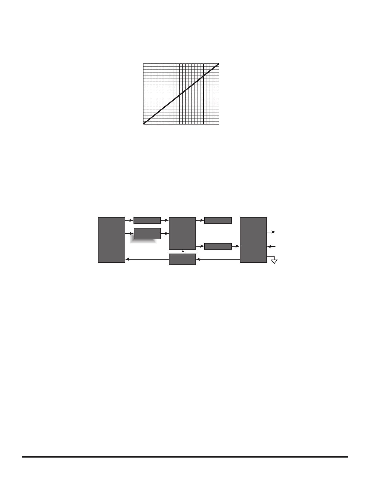
3.2 APPLICATION
Functional
Block
Diagram
Functional
Block
Diagram
4-20 mA Out
Power In
Pre-Amp Display
4-20mA
Micro-
processor
Tran smit ter
Power Supply
Optical
Sensor
I/O Circuit
Protection
Tem per atu re
Compensation
0
4
8
1
2
1
6
2
0
20 40 60 80 100
% of Range of Detection
mA DC Signal Output
Output Response Curve
Model IR-540/IR-541/IR-542 MicroSafe™ sensors are designed to detect and monitor CO2gas in ambient air.
Minimum sensitivity and scale resolution is 0.01%. Operating temperature range is -40° F. to +175° F. While the sensor
is capable of operating outside these temperatures, performance specifications are verified within the limit.
3.2.1 Sensor Placement/Mounting
Sensor location should be reviewed by facility engineering and safety personnel.
3.3 SPECIFICATIONS
Method of Detection
NDIR Optical
Electrical Classification
Class I; Groups B, C, D; Div. 1.
Detcon Model IR-540/IR-542 Carbon Dioxide Sensor PG.6
Page 7

Response Time
T50 < 15 seconds; T90 < 30 seconds
learing Time
C
90% < 30 seconds
Repeatability
± 3% FS
Range
0 - 0.3/0.5/1/2/3/5% withthe IR-540/IR-541
0-10/0-25/0-50/0-100% with the IR-542
Operating Temperature
-40° to +175° F
Accuracy
± 5% FS
Sensor Warranty
5 year pro-rated
Power Consumption
Normal operation = 86 mA (2.3 watts); Full alarm = 102 mA (<3 watts)
Zero Drift
< 0.05% per year
Output
Linear 4-20 mA DC
Input Voltage
11-28 VDC
3.4 OPERATING SOFTWARE
Operating software is menu listed with operator interface via the two magnetic program switches located under the
face plate. The two switches are referred to as “PGM 1” and “PGM 2”. The menu list consists of 3 items which
include sub-menus as indicated below. (Note: see the last page of this manual for a complete software flow chart.)
01. Normal Operation
a) Current Status
02. Calibration Mode
a) Zero
b) Span
03. Program Menu
a) Program Status
c) Calibration Level
3.4.1 Normal Operation
In normal operation, the display tracks the current status of the sensor and gas concentration and appears as:
“0.00 % CO2”. The mA current output corresponds to the monitoring level and range of 0-100% FS = 4-20 mA.
3.4.2 Calibration Mode
Calibration mode allows for sensor zero and span adjustments. “1-ZERO 2-SPAN”
3.4.2.1 Zero Adjustment
Zero is set in ambient air with no CO2gas present or with zero gas applied to the sensor. “AUTO ZERO”
3.4.2.2 Span Adjustment
Unless otherwise specified, span adjustment is performed at 50% of full-scale range of CO2. “AUTO SPAN”
Detcon Model IR-540/IR-542 Carbon Dioxide Sensor PG.7
Page 8

3.4.3 Program Mode
The program mode provides a program status menu, allows for the adjustment of alarm set point levels, and the
selection of the calibration gas level setting..
3.4.3.1 Program Status
The program status scrolls through a menu that displays:
* The gas type, range of detection and software version number. The menu item appears as: “CO2 RANGE V6.0”
* The calibration gas level setting. The menu item appears as: “CalLevel @ #.##%”
* Sensor temperature in °C appears as: “TEMPERATURE ## °C”
* The estimated remaining sensor life. The menu item appears as: “OPTICS AT 100%”
3.4.3.2 Calibration Level Adjustment
The Calibration level is adjustable from 10% to 90% of full-scale range. The menu item appears as: “CalLevel @ #.##%”
3.5 INSTALLATION
Optimum performance of ambient air/gas sensor devices is directly relative to proper location and installation practice.
3.5.1 Field Wiring Table
Detcon Model IR-540/IR-541/IR-542 CO2 sensor assemblies require three conductor connection between power
supplies and host electronic controllers. Wiring designators are
Maximum single conductor resistance between sensor and controller is 10 ohms. Maximum wire size for termination in the sensor assembly terminal board is 14 gauge.
AWG Wire_Dia. Meters Feet
20 0.812mm 1120 3350
18 1.024mm 1750 5250
16 1.291mm 2800 8400
14 1.628mm 4480 13,400
Note 1:
Note 2: Shielded cable may be required in installations where cable trays or conduit runs include high voltage
lines or other sources of induced interference.
Note 3: The supply of power must be from an isolating source with over-current protection as follows:
AWG
22 3A 16 10A
20 5A 14 20A
18 7A 12 25A
The RS-485 (if applicable) requires 24 gauge, two conductor, shielded, twisted pair cable between sensor and host
PC. Use Belden part number 9841. Two sets of terminals are located on the connector board to facilitate serial loop
wiring from sensor to sensor. Wiring designators are
This wiring table is based on stranded tinned copper wire and is designed to serve as a reference only.
Over-current Protection AWG Over-current Protection
(4-20 mA output)
A& B
+
(DC), –(DC) , and mA(sensor signal).
(IN) and A& B(OUT).
3.5.2 Sensor Location
Selection of sensor location is critical to the overall safe performance of the product. Five factors play an important
role in selection of sensor locations:
(1) Density of the gas to be detected
(2) Most probable leak or generation sources within the industrial process
(3) Ventilation or prevailing wind conditions
(4) Personnel exposure
(5) Accessibility for routine maintenance
Detcon Model IR-540/IR-542 Carbon Dioxide Sensor PG.8
Page 9
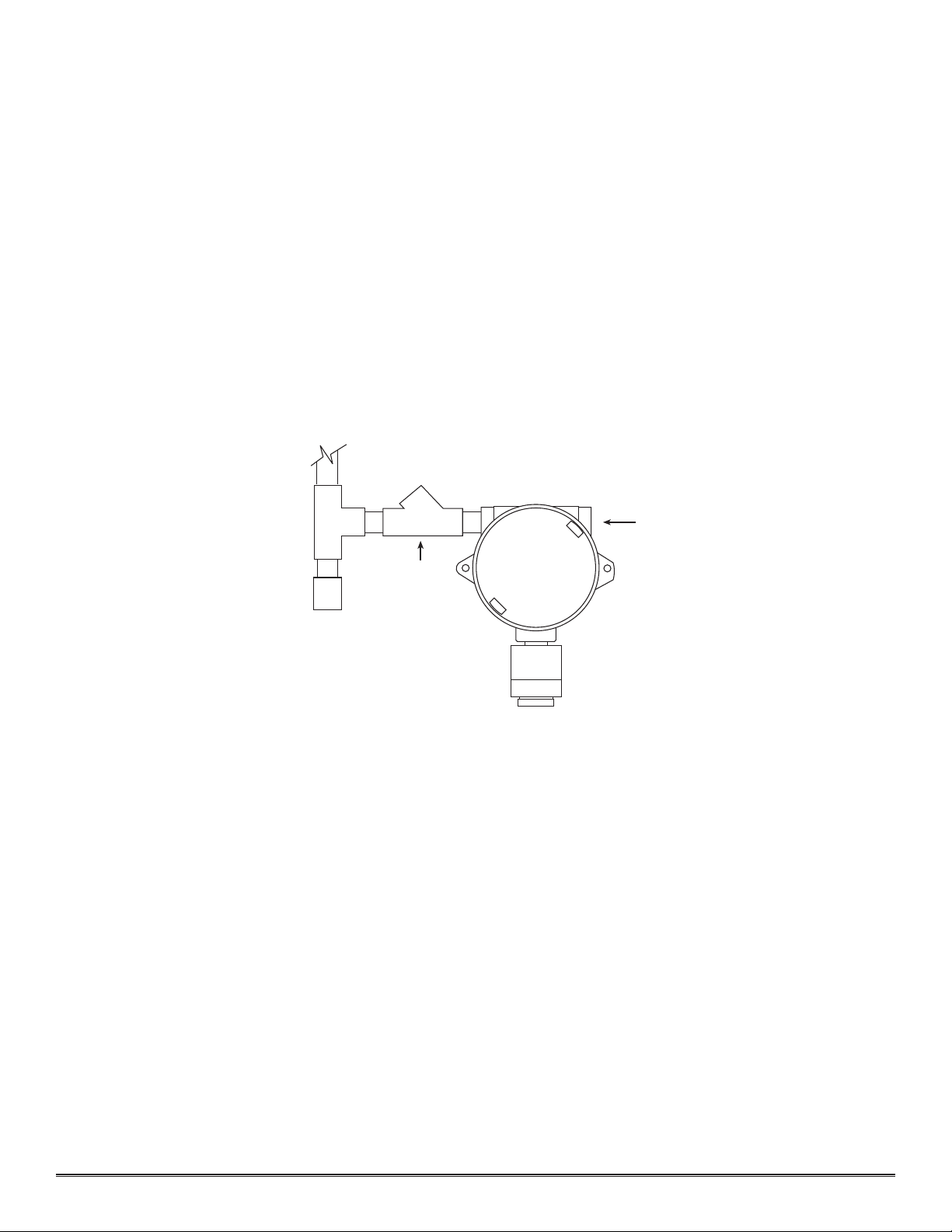
Density
EYS
Seal
Fitting
Drain
“T”
Plug any unused ports.
be located within 2-4 feet of grade as CO2will tend to settle in low lying areas.
- Placement of sensors relative to the density of CO2is such that sensors for the detection of CO2should
Leak Sources
tions of the sealed type where seals may either fail or wear. Other leak sources are best determined by facility engineers with experience in similar processes.
Ventilation
manner where the migration of gas clouds is quickly detected.
Personnel Exposure
Figure #1
Note:
orientation may result in false reading and permanent sensor damage.
In all installations, the sensor element in SS housing points down relative to grade (Fig. 1). Improper sensor
- Most probable leak sources within an industrial process include f langes, valves, and tubing connec-
- Normal ventilation or prevailing wind conditions can dictate efficient location of gas sensors in a
- The undetected migration of gas clouds should not be allowed to approach concentrated personnel areas such as control rooms, maintenance or warehouse buildings. A more general and applicable thought toward selecting sensor location is combining leak source and perimeter protection in the
best possible configuration.
3.5.3 Local Electrical Codes
Sensor and transmitter assemblies should be installed in accordance with all local electrical codes. Use appropriate
conduit seals. Drains & breathers are recommended. The sensor assemblies are designed to meet NEC and CSA
requirements for Class I; Groups B, C, D; Div. 1 environments.
3.5.4 Accessibility
Consideration should be given to easy access by maintenance personnel as well as the consequences of close proximity to contaminants that may foul the sensor prematurely.
Note:
EYD2 or equivalent are suitable for this purpose.
3.5.5 Installation Procedure
Note: See section 3.5.6 for special information on remote mounting applications in which the sensor (Model IR540-RS, IR-541-RS or IR-542-RS) is remotely mounted away from the transmitter (Model IR-540-RT, IR-541-RT or IR542-RT).
a) Remove the junction box cover and un-plug the control circuit by grasping the two thumb screws and pulling outward.
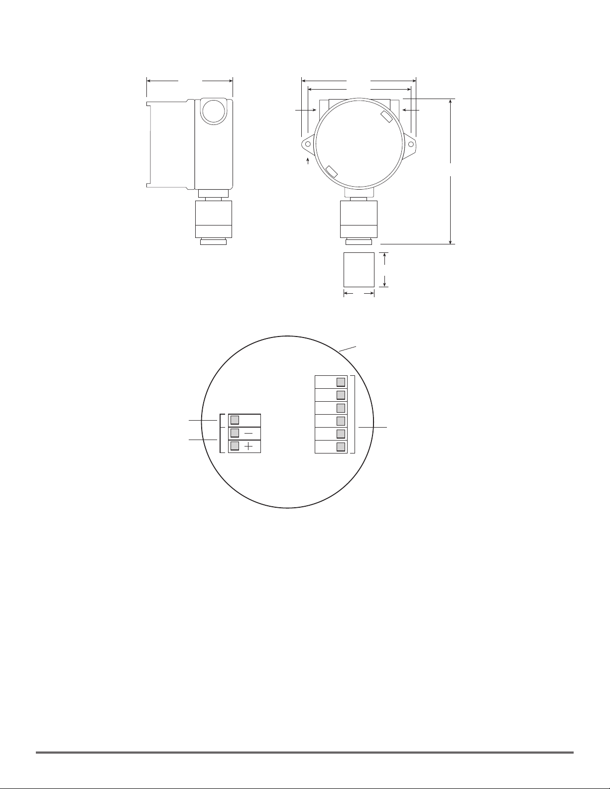
b) Securely mount the sensor junction box in accordance with recommended practice. See dimensional drawing (Fig. 2).
c) Observing correct polarity, terminate 3 conductor field wiring to the sensor base connector board in accordance
d) Replace the plug-in transmitter circuit and replace the junction box cover.
An appropriate conduit seal must be located within 18" of the sensor assembly. Crouse Hinds type EYS2,
with the detail shown in Figure 3.
Detcon Model IR-540/IR-542 Carbon Dioxide Sensor PG.9
Page 10
BLU
YEL
BLK
WHT
mA
VDC Power In
4-20 mA Output
BRN
RED
Sensor
Base Connector Board
4 3/4"
3/4" NPT
1/4" Dia.
Mounting Holes
8 1/4"
6 1/8"
5 1/2"
3/4" NPT
Rainshield/
Splashguard
2"
2 1/8"
Figure #2
Figure #3
3.5.6 Remote Mounting Applications
Some sensor mounting applications require that the gas sensor head be remotely mounted away from the sensor
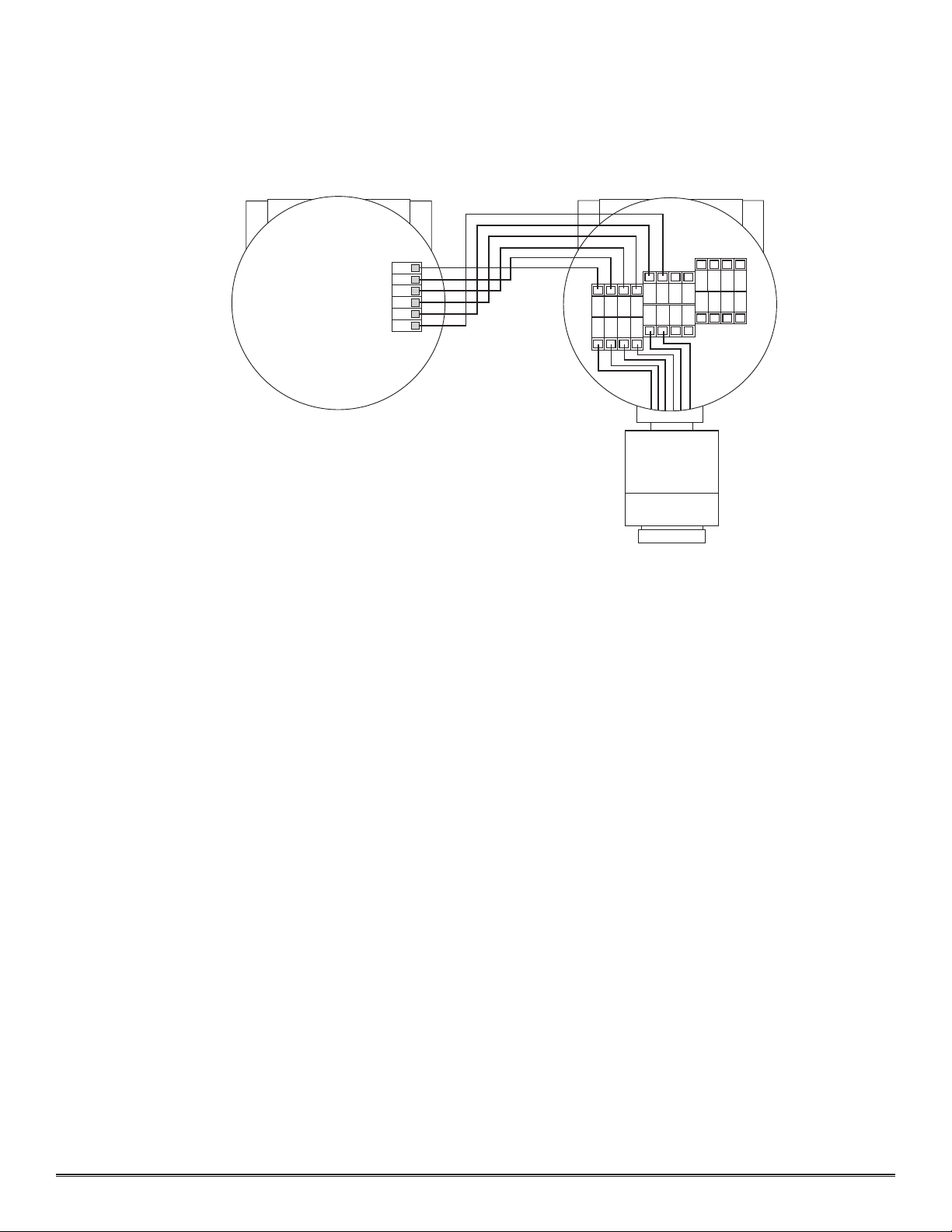
transmitter. This is usually true in instances where the gas sensor head must be mounted in a location that is difficult to access. Such a location creates problems for maintenance and calibration activities. Detcon provides the IR540/IR-541/IR-542 sensor in a remote-mount configuration in which the sensor (Model IR-540-RS, IR-541-RS or
IR542-RS) and the transmitter (Model IR-540-RT, IR-541-RT or IR542-RT) are provided in their own condulet housing and are interfaced together with a six conductor cable. Shielded cable is required and must be installed in its
own (unshared) conduit (use Alpha Wire Company #6342 cable). A maximum of 100 feet of separation is allowed.
Reference figure 4 for wiring diagram.
Detcon Model IR-540/IR-542 Carbon Dioxide Sensor PG.10
Page 11
1234
RED
BRN
WHT
BLK
Remote Transmitter
IR-540-RT
Remote Sensor
IR-540-RS
WHT
B
LK
YEL
BLU
RED
B
RN
56
YEL
BLU
Figure #4
3.6 START UP
Upon completion of all mechanical mounting and termination of all field wiring, apply system power and observe
the following normal conditions:
a) The “Fault” LED is off.
b) A reading of 0.00% CO2 should be indicated upon conclusion of a 12 second “warming up” cycle.
Note 1: If the display contrast needs adjustment, refer to section 3.10.
3.6.1 Initial Operational Tests
After a warm up period has been allowed for, the sensor should be checked to verify sensitivity to carbon dioxide
gas.
Material Requirements
* Detcon PN 6132 Threaded Calibration Adapter
* Span Gas 50% of full-scale range CO2in air at a controlled flow rate of 200 ml/min.
a) Attach the calibration adapter to the threaded sensor housing. Apply the test gas at a controlled f low rate of
200 ml/m. Observe that the LCD display increases to a level of 20% of full-scale range or higher.
b) Remove the test gas and observe that the LCD display decreases to “0.00 % CO2”
Initial operational tests are complete. Detcon CO2 sensors are pre-calibrated prior to shipment and will, in most
.
cases, not require significant adjustment on start up. However, it is recommended that a complete calibration test
and adjustment be performed within 24 hours of installation. Refer to calibration instructions in later text.
Detcon Model IR-540/IR-542 Carbon Dioxide Sensor PG.11
Page 12
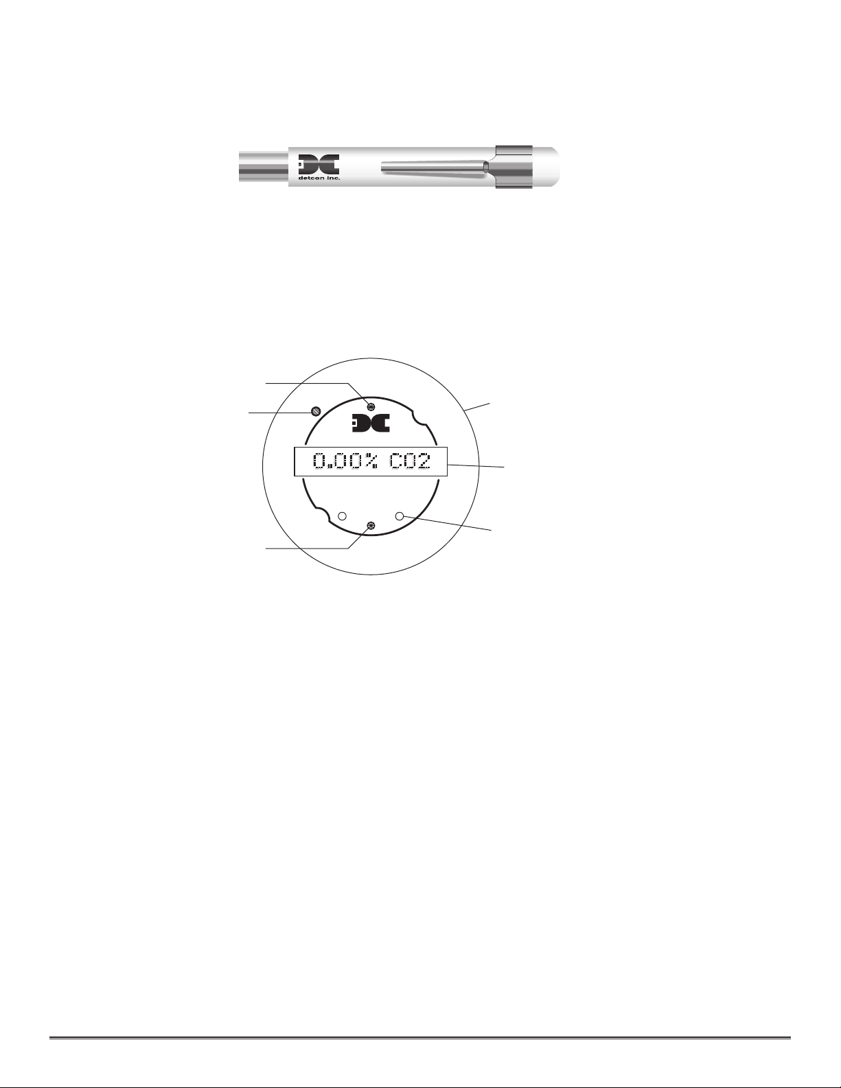
Magnetic Programming Tool
Figure #5
detcon inc.
Program Switch #2
FLT CAL
MicroSafe™ CO2 Gas Sensor
H
OUST ON, T EXA S
P
GM 2
PGM 1
MODEL IR-540
C
ONTRAST
Fault & Cal LEDs
Program Switch #1
Menu Driven Display
Plug-in Microprocessor Control Circuit
Display Contrast Adjust
3.6.2 Programming Magnet Operating Instructions
Operator interface to MicroSafe™ gas detection products is via magnetic switches located behind the transmitter
face plate. DO NOT remove the glass lens cover to calibrate or change programming parameters. Two switches
labeled “PGM 1” and “PGM 2” allow for complete calibration and alarm level programming without removing the
enclosure cover, thereby eliminating the need for area de-classification or the use of hot permits.
A magnetic programming tool (see figure 5) is used to operate the switches. Switch action is defined as momentary
contact, 3 second hold, and 30 second hold. In momentary contact use, the programming magnet is waved over a
Figure #6
switch location. In 3 second hold, the programming magnet is held in place over a switch location for 3 or more
seconds. In 30 second hold, the programming magnet is held in place over a switch location for 30 or more seconds. Three and thirty second hold is used to enter or exit calibration and program menus while momentary contact is used to make adjustments. The location of “PGM 1” and “PGM 2” are shown in figure 6.
NOTE: If, after entering the calibration or program menus, there is no interaction with the menu items for more
than 30 seconds, the sensor will return to its normal operating condition.
3.7 CALIBRATION
Material Requirements
* Detcon PN 3270 MicroSafe™ Programming Magnet
* Detcon PN 6132 Threaded Calibration Adapter
* Span Gas containing the applicable calibration gas in air. Span gas concentration is recommended at 50% of
full-scale range (which is the factory default) at a controlled f low rate of 200 ml/min. Other concentrations can
be used as long as they fall within 10% to 90% of range. See section 3.7.2 for details.
3.7.1 Calibration Procedure - Zero
NOTE: Before performing a zero calibration, be sure there is no CO2gas present.
a) Enter the calibration menu by holding the programming magnet stationary over “PGM 1” (see figure 6) for 3 sec-
onds until the display reads “1-ZERO 2-SPAN”, then withdraw the magnet. Note that the “CAL” LED is on.
b) Next, enter the zero menu by holding the magnet stationary over “PGM 1” for 3 seconds until the display
reads: “ZERO 0%”, then withdraw the magnet. The sensor has now entered the auto zero mode. When it is
complete the display will read “ZERO COMPLETE” for 5 seconds and then return to the normal operations
menu, “0.00 % CO2”.
Detcon Model IR-540/IR-542 Carbon Dioxide Sensor PG.12
Page 13

NOTE 1: If the circuitry is unable to adjust the zero to the proper setting the sensor will enter a calibration
fault mode which will cause the display to alternate between the sensor’s current status reading and the calibration fault screen which appears as: “CAL FAULT” (see section 3.7.3).
NOTE 2: When a “cal fault” occurs, the sensor microprocessor retains its previous calibration references.
Zero calibration is complete.
3.7.2 Calibration Procedure - Span
CAUTION:
Verification of the correct calibration gas level setting and calibration span gas concentration is
required before “span” calibration. These two numbers must be equal.
Calibration consists of entering the calibration function and following the menu-displayed instructions. The display
will ask for the application of span gas in a specific concentration. This concentration is equal to the calibration gas
level setting. The factory default setting for span gas concentration is 50% of full-scale range. In this instance, a
span gas containing a concentration equal to 50% of full-scale range is required. If a span gas containing 50% of
range is not available, other concentrations may be used as long as they fall within 10% to 90% of range. However,
any alternate span gas concentration value must be programmed via the calibration gas level menu before proceeding with span calibration. Follow the instructions below for span calibration.
a) Verify the current calibration gas level setting as indicated by the programming status menu. To do this, follow
the instructions in section 3.8 and make note of the setting found in listing number 14. The item appears as
“CalLevel @ x.xx%”.
b) If the calibration gas level setting is equal to your calibration span gas concentration, proceed to item “f”. If
not, adjust the calibration gas level setting so that it is equal to your calibration span gas concentration, as
instructed in items “c” through “e”.
c) Enter the programming menu by holding the programming magnet stationary over “PGM 2” for 30 seconds
until the display reads “VIEW PROG STATUS”, then withdraw the magnet. At this point you can scroll
through the programming menu by momentarily waving the programming magnet over “PGM 1” or “PGM 2”.
The menu options are: View Program Status, and Set Cal Level.
d) From the programming menu scroll to the calibration level listing. The menu item appears as: “SET CAL
LEVEL”. Enter the menu by holding the programming magnet stationary over “PGM 1” for 3 seconds until
the display reads “CalLevel @ ##%”, then withdraw the magnet. Use the programming magnet to make an
adjustment to “PGM 1” to increase or “PGM 2” to decrease the display reading until the reading is equal to the
desired calibration span gas concentration. Exit to the programming menu by holding the programming magnet
over “PGM1” for 3 seconds.
e) Exit back to normal operation by holding the programming magnet over “PGM 2” for 3 seconds, or automati-
cally return to normal operation in 30 seconds.
f) From the calibration menu “1-ZERO 2-SPAN” (section 3.7.1-a) proceed into the span adjust function by
holding the programming magnet stationary over “PGM 2” for 3 seconds until the display reads “APPLY
x.xx% CO2” then withdraw the programming magnet. The x’s indicate the gas concentration requested.
g) Apply the calibration gas at a flow rate of between 200 milliliters per minute. As the sensor signal changes, the
display will change to “SPAN XX%”. The “XX” part of the reading indicates the actual gas reading which will
increase until the sensor stabilizes. When the sensor signal is stable it will auto span to the request concentration and the display will change to “SPAN COMPLETE” for two seconds and then “REMOVE GAS”.
Remove the gas. When the signal level has fallen below 10% of full scale, the display will return to the normal
operation menu, “0.00 % CO2”.
NOTE 1: If the circuitry is unable to adjust the span to the proper setting the sensor will enter into the calibration fault mode which will cause the display to alternate between the sensor’s current status reading and the calibration fault screen which appears as: “CAL FAULT” (see section 3.7.3).
NOTE 2: If, after entering the span function, more than one minute elapses before calibration gas is applied,
the sensor will enter the calibration fault mode which will cause the display to alternate between the sensor’s
current status reading and the calibration fault screen which appears as: “CAL FAULT” (see section 3.7.3).
Span calibration is complete.
Detcon Model IR-540/IR-542 Carbon Dioxide Sensor PG.13
Page 14

3.7.3
1. Upon entering the calibration menu, the 4-20 mA signal drops to 2 mA and is held at this level until you
2. If during calibration the sensor circuitry is unable to attain the proper adjustment for zero or span, the sensor will
3.7.4 Calibration Frequency
In most applications, quarterly zero calibration and annual span calibration intervals will assure reliable detection.
However, industrial environments differ. Upon initial installation and commissioning, close frequency tests should
be performed monthly. Test results should be recorded and reviewed to determine a suitable calibration interval.
Additional Notes
return to normal operation.
enter into the calibration fault mode which will activate fault alarm functions (see section 3.9) and cause the display to alternate between the sensor’s current status reading and the calibration fault screen which appears as:
“CAL FAULT”. If this occurs you may attempt to recalibrate by entering the calibration menu as described in
section 3.8.1-a. If the sensor fails again, defer to technical trouble shooting.
3.8 STATUS OF PROGRAMMING, CALIBRATION LEVEL, TEMPERATURE, AND SENSOR LIFE
The programming menu has a programming status listing that allows the operator to view the gas, range, and software version number of the program, as well as the calibration gas level setting, sensor temperature, and estimated
remaining sensor life. The programming menu also allows the calibration gas level setting (see section 3.72).
The following procedure is used to view the programming status of the sensor:
a) First, enter the programming menu by holding the programming magnet stationary over “PGM 2” for 30 sec-
onds until the display reads “VIEW PROG STATUS”, then withdraw the magnet. At this point you can
scroll through the programming menu by momentarily waving the programming magnet over “PGM 1” or
“PGM 2”. The menu options are: View Program Status, and Set Cal Level.
b) Next, scroll to the “VIEW PROG STATUS” listing and then hold the programming magnet over “PGM 1”
for 3 seconds. The menu will then automatically scroll, at five second intervals, through the following information before returning back to the “VIEW PROG STATUS” listing.
The gas type, range of detection and software version number. The menu item appears as:
1 2 - The calibration gas level setting. The menu item appears as: “CalLevel @ xx%”
3 - Sensor temperature in °C appears as: “TEMPERATURE xx °C”
4 - The estimated remaining sensor life. The menu item appears as: “OPTICS AT 100%”
c) Exit back to normal operations by holding the programming magnet over “PGM 2” for 3 seconds, or automati-
cally return to normal operation in 30 seconds.
“CO2 RANGE V6.0”
3.9 PROGRAM FEATURES
Model IR-540/IR-541/IR-542 MicroSafe™ Sensors incorporate a comprehensive program to accommodate easy
operator interface and fail-safe operation. Program features are detailed in this section. Each sensor is factory tested,
programmed, and calibrated prior to shipment.
Over Range
When the sensor detects gas greater than 100% of the full-scale range, it will cause the display to flash “OVERRANGE” on and off.
Optics Life
The Optics Life feature is a reference based on the signal output from the optical sensor. When an optical sensor
life of 25% or less remains, the optical sensor should be replaced within a reasonable maintenance schedule.
Detcon Model IR-540/IR-542 Carbon Dioxide Sensor PG.14
Page 15

Calibration Fault
If during calibration the sensor circuitry is unable to attain the proper adjustment for zero or span, the sensor will
enter into the calibration fault mode and cause the display to alternate between the sensor’s current status reading and
the calibration fault screen which appears as: “CAL FAULT.2”.
The following conditions will cause a calibration fault:
1 - Zero calibration cannot converge.
2 - Auto span cannot converge (too noisy or too unstable).
3 - Span gas is not applied before 1 minute elapses.
Fail-Safe/Fault Supervision
Model IR-540/IR-541/IR-542 MicroSafe™ sensors are programmed for fail-safe operation. All of the fault conditions
listed below will activate the fault relay, illuminate the fault LED, cause the mA output to drop to zero (0) mA, and
cause the display to read its corresponding fault condition.
Memory Error
If the processor can’t save values to memory, the display will indicate: “MEMORY ERROR”.
Zero Fault
If the sensor should drift below –0.02%, the display will indicate: “ZERO FAULT”.
Lamp Fault
If the lamp signal is lost, the display will indicate: “LAMP FAULT.2”.
Reference Peak High Fault
If the reference peak signal is too high (>3600), the display will indicate: “SIGNAL FAULT.31”.
Active Peak High Fault
If the active peak signal is too high (>3600), the display will indicate: “SIGNAL FAULT.32”.
Reference Peak Low Fault
If the reference peak signal is too low (<500), the display will indicate: “SIGNAL FAULT.41”.
Active Peak Low Fault
If the active peak signal is too low (<500), the display will indicate: “SIGNAL FAULT.42”.
Reference Peak to Peak Low Fault
If the reference peak to peak signal is too low (<200), the display will indicate: “SIGNAL FAULT.51”.
Active Peak to Peak Low Fault
If the active peak to peak signal is too low (<200), the display will indicate: “SIGNAL FAULT.52”.
3.10 DISPLAY CONTRAST ADJUST
Model IR-540/IR-541/IR-542 MicroSafe™ sensors feature a 16 character backlit liquid crystal display. Like most
LCDs, character contrast can be affected by viewing angle and temperature. Temperature compensation circuitry
included in the MicroSafe™ design will compensate for this characteristic, however temperature extremes may still
cause a shift in the contrast. Display contrast can be adjusted by the user if necessary. However, changing the contrast requires that the sensor housing be opened, thus declassif ication of the area is required.
To adjust the display contrast, remove the enclosure cover and use a jewelers screwdriver to turn the contrast
adjust screw located beneath the metallic face plate. The adjustment location is marked “CONTRAST”. See figure 6
for location.
Detcon Model IR-540/IR-542 Carbon Dioxide Sensor PG.15
Page 16

3.11 OPTICAL SENSOR REPLACEMENT PROCEDURE
Should the optical gas sensor element (part number 370-365878-111 or 370-287724-232) require replacement, use the
following procedure:
1 - (A) If the sensor is mounted in a classified area, system power to the transmitter must first be removed before
proceeding further.
(B) If in an unclassified area, remove front enclosure cover and unplug transmitter module.
2 - Remove lower half of sensor housing using an alan wrench (3 screws).
3 - Remove existing optical sensor and replace with new optical sensor (part number 370-365878-111 or 370-287724-
232).
4 - Re-install lower half of sensor housing.
5 - Restore system power (if classified) or plug in transmitter module and replace enclosure cover (if unclassified).
6 - As the unit reports “WARMING UP” message, use the magnetic programming tool and swipe across PGM1 or
PGM2. This will take the unit into a one-time gain setting mode which takes 1 minute to complete.
7 - Perform a new zero calibration followed by a new span calibration (see section 3.7).
3.12 TROUBLE SHOOTING GUIDE
Calibration Faults (CalFault.2)
Calibration Faults (Zero or Span) can be cleared by successfully repeating the calibration attempt. Refer to the appropriate section in the Operator Manual and follow procedure.
Clearing Faults (Memory Error, LampFault.2, and Signal Faults.XX)
If a Fault Diagnostic occurs (Memory Error, Lamp Fault, or Signal Fault.XX) it may be a permanent problem or temporary. If
it is a temporary fault, it may be cleared using the following 1) and 2) actions. If it can not be cleared then it is a permanent
problem and advanced troubleshooting may be necessary.
1) Unplug and replug transmitters to cycle power. Determine if fault has cleared.
2) Re-initialize unit by unplugging and re-plugging transmitter and then immediately swiping your magnet over PGM1. The
unit will go into an initializing mode and reset the optical gain settings. Observe unit as the gain setting (GN) is counted down
and Ia or Ir is counted up to 2700. Record the gain set value last reported as Ia or Ir reaches 2700. Next record the final Ia and
Ir values which are displayed next. Finally record the temperature which is displayed last. Determine if fault has cleared.
Normal Readings are defined below and should be recorded to discuss with Detcon Technical Service Staff:
Gain Set:55-130
Ir: 2000-2700
Ia: 1800-2700
Temp: 32C 40C (approximately 10C higher than ambient temperature)
3) Contact Detcon for service and repair if above mentioned troubleshooting actions have not solved problem.
Zero Fault
Zero Fault is an indication that the zero level has drifted below –10% of range.
Zero Fault can be cleared by re-calibrating zero in target gas “free” air.
Non-readable display
1. If display has blue background when hot, install sunshade to reduce temperature.
2. If poor contrast, adjust contrast pot accordingly.
Nothing Displayed – Transmitter not responding
1. Verify condulet has no accumulated water or abnormal corrosion.
2. Verify required DC power is applied to correct terminals.
3. Swap with a known-good transmitter to determine if transmitter is faulty.
Detcon Model IR-540/IR-542 Carbon Dioxide Sensor PG.16
Page 17

Bad 4-20 mA output
1. Check that wiring is connected to correct terminal outputs.
2. Swap with a known-good transmitter to determine if transmitter is faulty
Unstable output/Sudden Spiking/Nuisance Alarms
. Check condulet for accumulated water.
1
2. Check transmitter and Terminal PCB for abnormal corrosion.
3. Determine if problem correlates with condensation cycles.
4. Add/change Detcon condensation prevention packet.
5. Check for unstable power supply.
6. Check for inadequate grounding.
7. If correlates with radio communications then use Detcon RFI filter accessory.
8. Contact Detcon for assistance in optimizing shielding, grounding, and RFI protection.
Excessive Span Drift or Slow Response
1. Verify correct cal gas flow rate and proper use of the cal gas adapter.
2. Check validity of cal gas via the expiration date and use pull tube if necessary.
3. Check for obstructions through s/s sinter element (including being wet).
4. Replace plug-in sensor if Optics Life is <25%.
Drifting Zero
It may be the correct reading if there are real gas leaks or the sensor was zero calibrated when actual gas was present and subsequently cleared.
1. Recalibrate zero using target gas “free” sample.
2. Replace plug-in sensor if Optics Life is <25%.
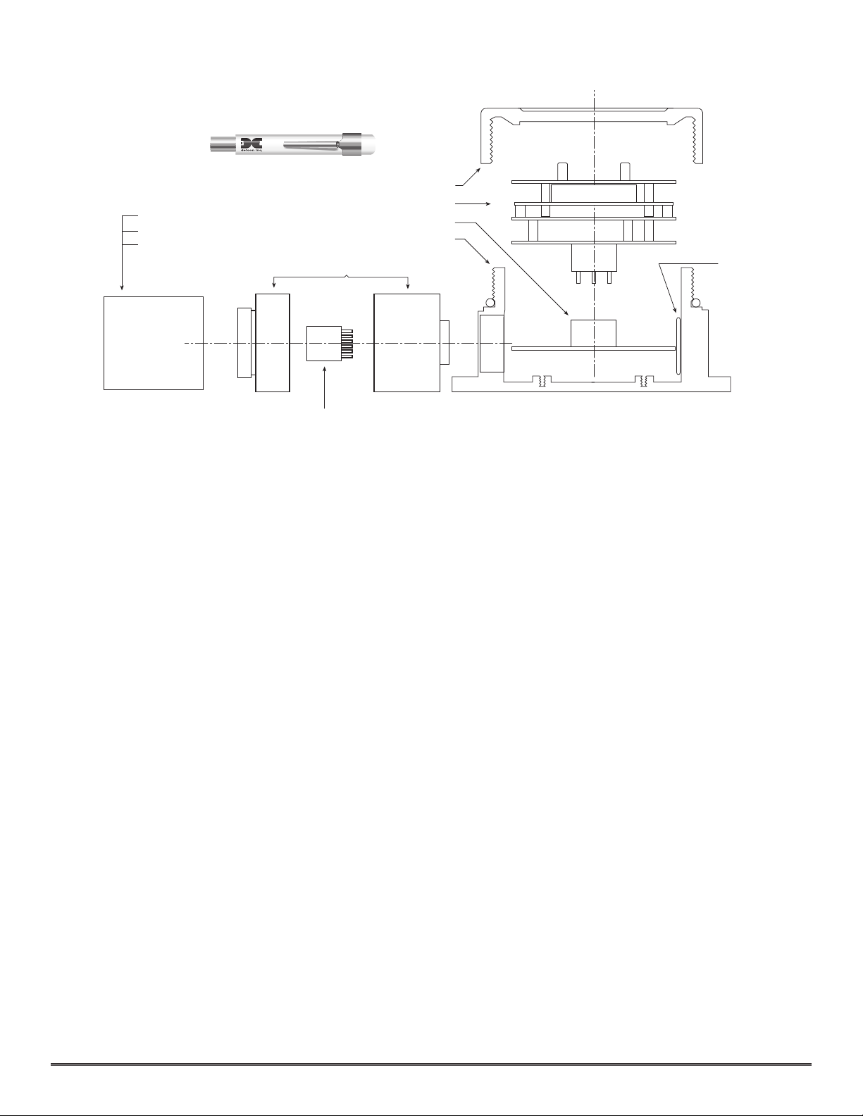
3.13 SPARE PARTS LIST
613-010000-000 Sensor rain shield
613-120000-000 Sensor splash guard
943-000006-132 Threaded Calibration Adapter
390-000088-000 IR sensor housing assembly (plug-in detector PN370-365878-111 or 370-287724-232,
not included)
370-365878-111 Field replaceable optical plug in sensor (for IR-540 .3 to 5% range)
370-365878-222 Field replaceable optical plug in sensor (for IR-541 .3 to 5% range)
370-287724-232 Field replaceable optical plug in sensor (for 10 to 100% range)
925-405400-xxx IR-540 Plug-in control circuit (where xxx is 0X3 = 0.30%, 0X5 = 0.50%, 001 = 1%,
1X2 = 1.2%, 003 = 3%, and 005 = 5%)
925-415400-xxx IR-541 Plug-in control circuit (where xxx is 0X3 = 0.30%, 0X5 = 0.50%, 001 = 1%,
1X2 = 1.2%, 003 = 3%, and 005 = 5%)
925-425400-xxx IR542 Plug-in control circuit (where xxx is 010 = 10%, 025 = 25%, 050 = 50%, 100 = 100%)
500-002226-001 IR Connector board
327-000000-000 Programming Magnet
897-850800-000 3 port enclosure less cover
897-850700-000 Enclosure glass lens cover
960-202200-000 Condensation prevention packet (replace annually).
Detcon Model IR-540/IR-542 Carbon Dioxide Sensor PG.17
Page 18
3.14 WARRANTY
Spash Guard
Rain Shield
E
nclosure less cover
IR Connector Board
C
alibra tion Adap ter
Enclosure glass lens cover
Plug-in control circuit
F
ield replaceable plug-in optical sensor
IR Sensor Housing Assembly
Programming Magnet
Condensation
P
revention Packet
(replace annually)
Detcon, Inc., as manufacturer, warrants each NDIR optical plug in sensor (part no. 370-365878-111 or 370-287724-
232), for a pro-rated five year period under the conditions described as follows: The warranty period begins on the
date of shipment to the original purchaser and ends five years thereafter. The sensor element is warranted to be free
from defects in material and workmanship. Should any sensor fail to perform in accordance with published specif ications within the warranty period, return the defective part to Detcon, Inc., 3200 A-1 Research Forest Dr., The
Woodlands, Texas 77381, for necessary repairs or replacement.
3.15 SERVICE POLICY
Detcon, Inc., as manufacturer, warrants under intended normal use each new MicroSafe™ plug-in control circuit to
be free from defects in material and workmanship for a period of two years from the date of shipment to the original purchaser. Detcon, Inc., further provides for a five year fixed fee service policy wherein any failed transmitter
shall be repaired or replaced as is deemed necessary by Detcon, Inc., for a fixed fee of $65.00. The fixed fee service
policy shall affect any factory repair for the period following the two year warranty and shall end five years after
expiration of the warranty. All warranties and service policies are FOB the Detcon facility located in The
Woodlands, Texas.
Detcon Model IR-540/IR-542 Carbon Dioxide Sensor PG.18
Page 19
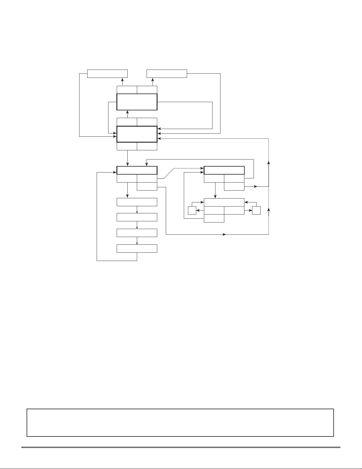
3.16 SOFTWARE FLOW CHART
NORMAL
OPERATION
CALIBRATION
PGM1 (3) PGM2 (3)
1-ZERO 2-SPAN
LEGEND
PGM1 - program switch location #1
PGM2 - program switch location #2
(M) - momentary pass of magnet
(
3) - 3 second hold of magnet
(30) - 30 second hold of magnet
INC - increase
DEC - decrease
# - numeric value
AUTO ZERO AUTO SPAN
LEL 0-100 V#.#
PGM1 (3) PGM2 (M)
VIEW PROG STATUS
PGM2 (3)
CAL LEVEL @ ##%
PGM1 (3) PGM1 (M)
P
GM2 (30) PGM2 (M)
OPTICS AT ##%
TEMPERATURE ##∞C
PGM1 (M) PGM2 (M)
PGM1 (3)
CAL LEVEL @ ##%
INC
DEC
PGM1 (3) PGM2 (M)
SET CAL LEVEL
PGM2 (3)
Shipping Address: 3200 A-1 Research Forest Dr., The Woodlands, Texas 7381
Mailing Address: P.O. Box 8067, The Woodlands, Texas 77387-8067
phone 888-367-4286, 713-559-9200 • fax 281-292-2860 • www.detcon.com • [email protected]
Detcon Model IR-540/IR-542 Carbon Dioxide Sensor PG.19
 Loading...