

Page 1

deta
#40 DISK TYPE TOOL CHANGER SYSTEM
INTERNATIONAL
USER MANUAL
This manual is applicable to model:
MR4AL
BT40/CAT40/DIN40/HSK50A/HSK63A
Revised date:2014/05/23
Page 2

Contents Page
1、Tool Changer System Mechanical Specification & Drawing
·······················································································
2、Power Supply Specification for Electrical Control ··························
3、Electrical Control ·········································································
4、Electrical Control Protection Programming ·································
5、Installation Procedure ··································································
6、Original Setting··············································································
7、Trouble Shooting···········································································
02
05
06
07
08
10
11
8、Maintenance ·················································································
16
1
Page 3

1、Tool Changer System Mechanical Specification &
Drawings :
1-1. Specification:
Item Model
Tool Capacity 24T
Maximum Tool Diameter 75mm
Max. Tool Length 300mm
Max. Tool Weight 7Kgf
Total Tool Weight 120 Kgf
MR4AL
CAM BOX Speed
(CAM BOX Only)
Magazine Speed 0.6 sec. / tool (60Hz)
Tool Selection Two Way Random Selection
1.5 sec. (60Hz)
2
Page 4
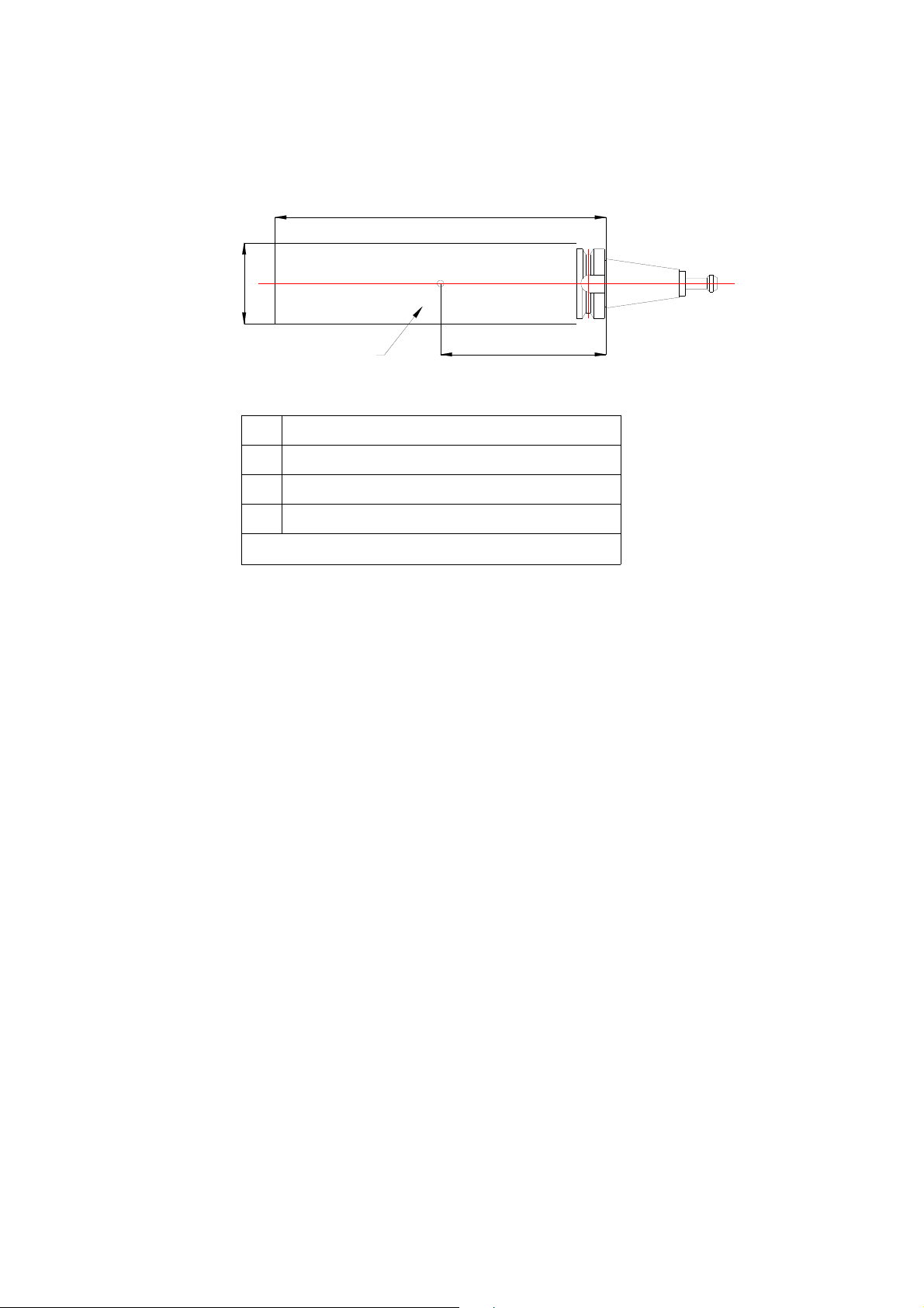
1-2. Maximum Tool Rotational Inertia Diagram:
Drawing:
A
C
MAX TOOL Weight D kgf
A
B
C
D
MOMENT=D*B(≦10.29N-m)
tool length
tool median point(A/2)
tool diameter
tool weight
B
3
Page 5

1-3. Drawings:
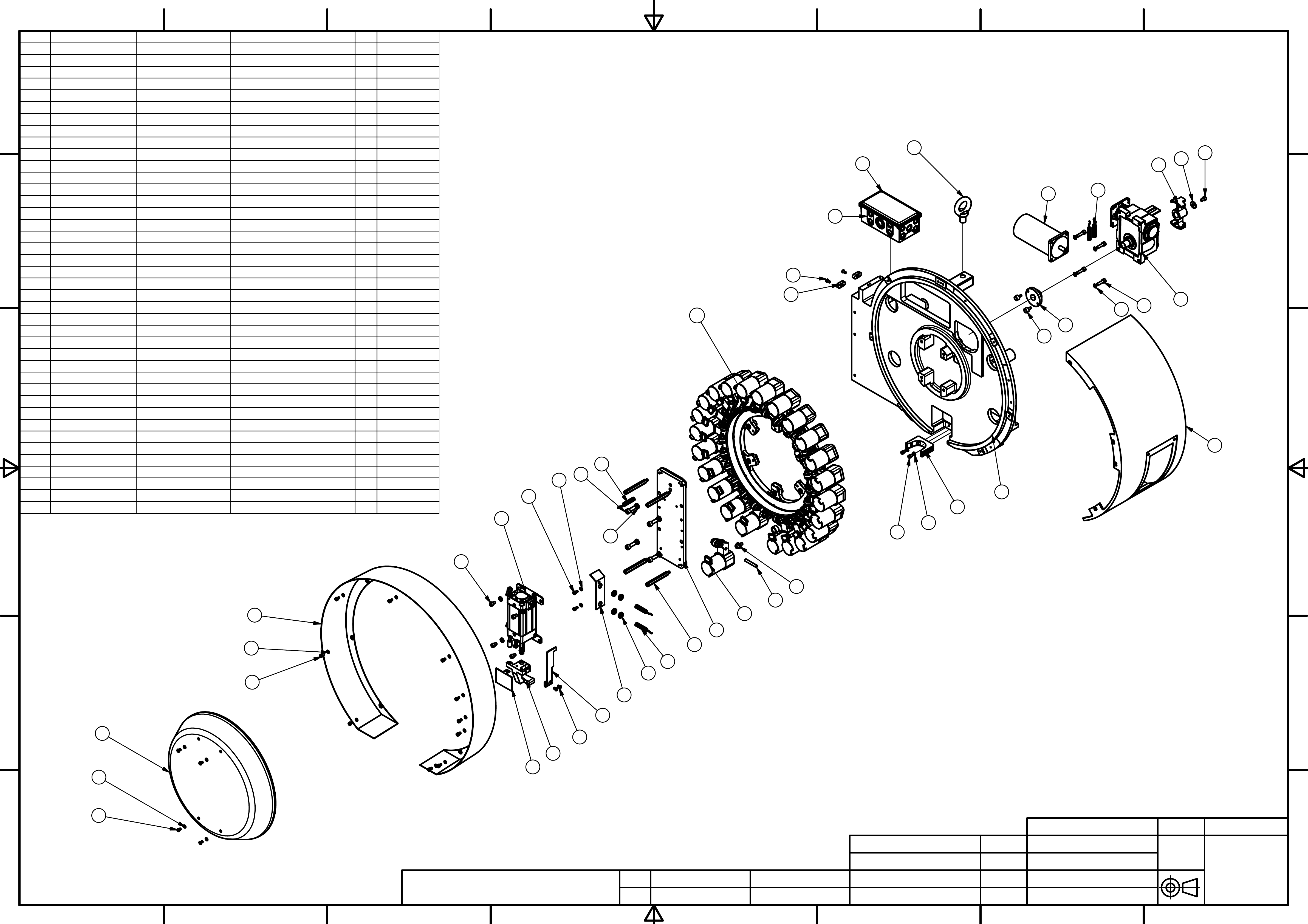
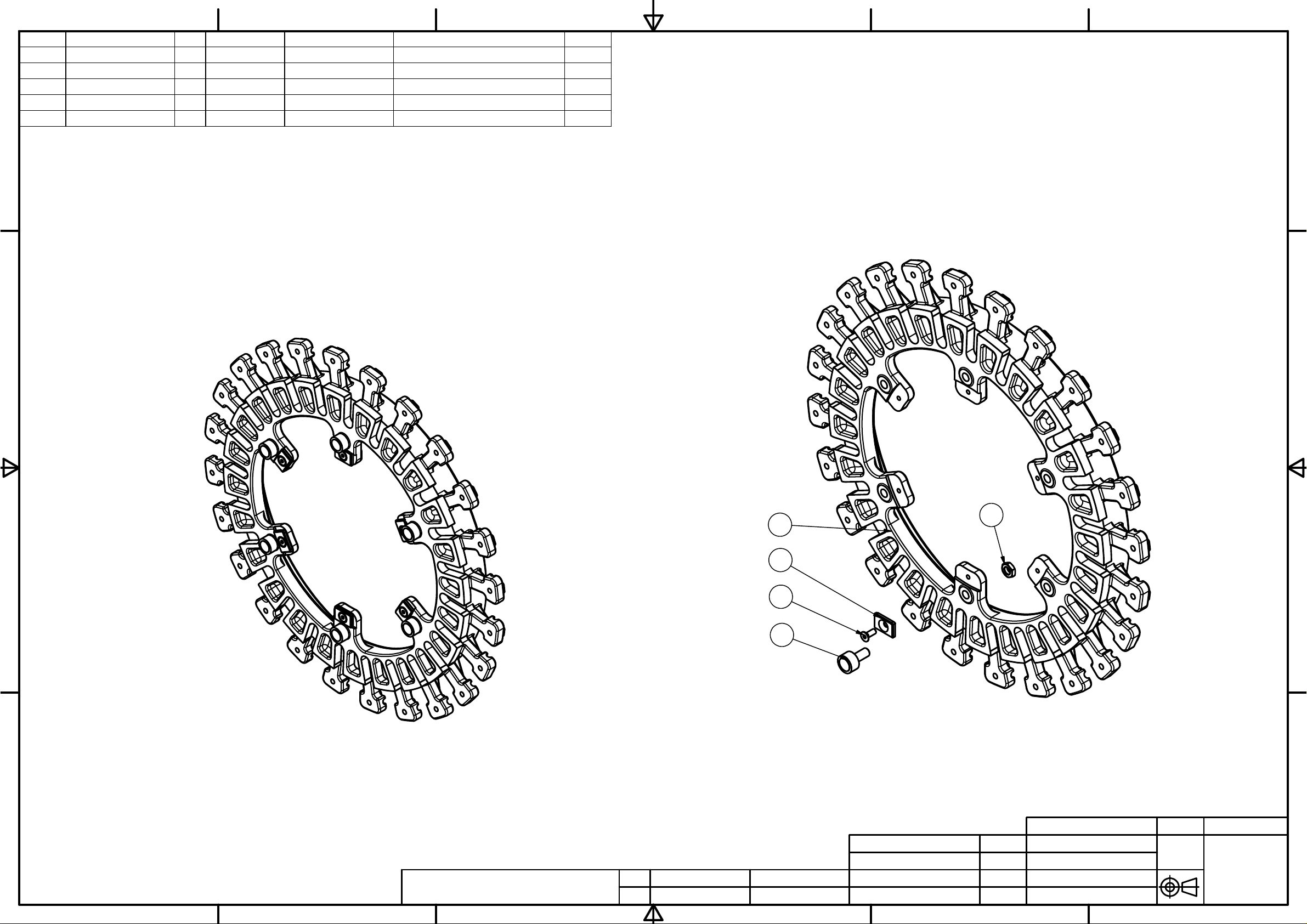
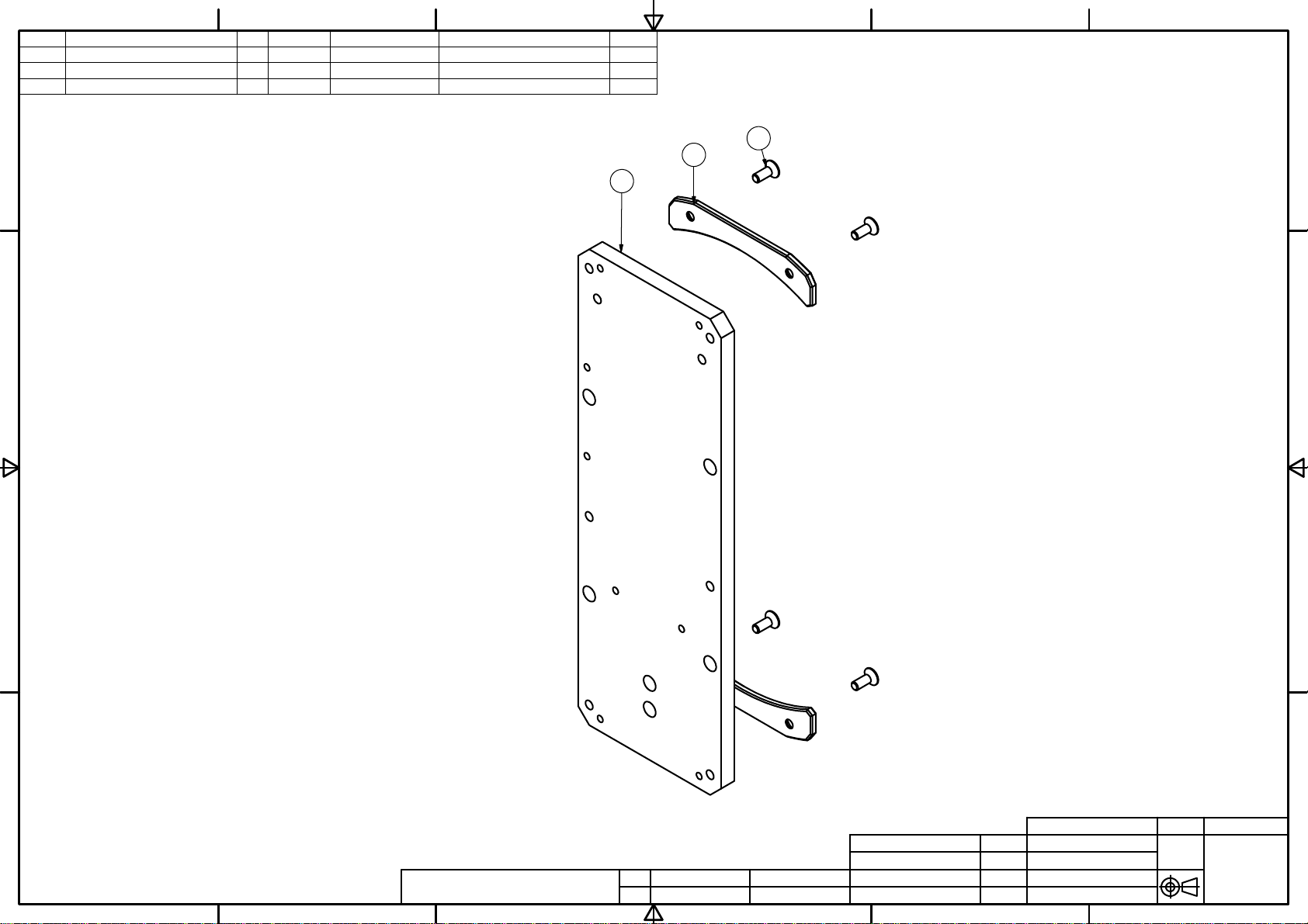
Assembly drawing and part list for disk type tool magazine, CAM BOX
and tool changing arm as per attached drawings and list.
4
Page 6
8
7
6
5
4
3
2
1
TITLE-CPART NO.ITEM NO
1
F F
4
5
7
11
14
MR4AK0001J02
MR4AK0002A002
MR4AK0004A003
MR4AK0025A04
MR4AK0005F01-T-10
MR4AK0010A066
MR4AK0018B01
MR4AK0006A068
MR4AK0026C019
R4KKV0009A0110
MR4AK0013A02
MR4AK0014Z0112
MR4AK028AB01-0113
MR4AK000003A02
本體
刀盤組
壓缸固定鈑組
倒刀定位座
倒刀壓缸
前蓋支撐桿
倒刀塊
固定鈑
刀套固定桿
渦輪減速機1:40
馬達
驅動軸
Cylinder Mounting Plate Moudule
Pocket Positioning Seat
TITLE-E
Bady
Tool Disk Module
Pneumatic Cylinder
Support Rod
Cover Plate倒刀蓋鈑
Tool Tilt Block
Sensor BlockSensor感應鈑
Sensor Lock BlockSensor
Shaft
Woem Gear
MOTOR
Tool Disk Driver
QTY.
1
1
1
4
1
1
1
1
1
1
MATERIAL
FC30
1
1
Nylon+40纖
市購品
SS41
SS41(2t)
S45C
SS41(3t)
SS411
S45C24
市購品
市購品
S45C
22
39
13
36
31
16
21
15
E E
17
EB000000CF6G
MR4AK0036A0116
MR4AK0007A05
MR4AK0034A0318
MR4A-0019A0119
P40K-1250112-0120
SR400000000321
EB10AL201183-00A22
EB20AL201183-00A23
MR4AK0035A0224
WA000000000825
M8xP1.25x30L26
M827
M628
曲線滾輪
定位感應片
壓缸前蓋
刀庫前外罩
承靠塊
刀套
近接開關
電控盒
電控盒蓋
CAMBOX
內六角承窩頭螺栓
外罩
墊片
平墊圈
平墊圈
Roller
Positioning Sensor Block
Front Of Cover
MAG Front Cover
Positioning Key
PocketBT
Proximity Sensor
CE Electric Box
CE Electric Box COVER
COMBOX COVER
Washer
Hexagon Socket Heard Screw
Finshed Circular Plain Washer
Finshed Circular Plain Washer
1
1
2
24
5
1
1
24
15
CF6B2
SS41
ABS
FRP1
S45C
市購品
ADC 12
ADC 12
SS411
市購品
4
4
23
31
19
27
2
14
15
26
12
29
D D
M8xP1.25x20L
M6xP1.0x10L30
M6xP1.0x12L31
M1032
M10xP1.5x30L33
M634
M6xP1.0 x12L35
M8xP1.25x12L36
M6xP1.0x10L37
M1238
BT000000002039
M6xP1.0x10L40
內六角承窩頭螺栓
內六角承窩頭螺栓
圓頭內六角承窩頭螺絲
彈簧墊圈
內六角承窩頭螺栓
彈簧墊圈
內六角承窩頭螺栓
內六角承窩頭螺栓
圓頭內六角承窩頭螺絲
六角螺帽
環首螺栓 M20
圓頭內六角承窩頭螺絲
Hexagon Socket Heard Screw
Hexagon Socket Heard Screw
Hexagon Socket Button Heard Screw
Spring Lock Washer
Hexagon Socket Heard Screw
Spring Lock Washer
Hexagon Socket Heard Screw
Hexagon Socket Heard Screw
Hexagon Socket Button Heard Screw
Hexagon Socket Button Heard Screw
24
2
2
11
4
4
4
4
5
4Nut
1
4
5
35
34
33
21
32
1
4
34
35
24
C C
36
2
11
18
3
28
21
38
30
B B
9
10
6
20
17
8
7
28
40
37
UNIT NO.
QUANTITY
MATERIAL
NO.
圖框更新版本
>0 ±0.1
A A
>6 ±0.2
2009/12/29
>30 ±0.3
>120 ±0.5
>350 ±0.8
>1000±1.2
deta INTERNATIONAL
TEL:886-4-25617722 FAX:886-4-25617177
NAME
DRAWING DESING CHECK APPROVE
ANGEL2014/5/26
PART NO.
MR4AL0001A01
SCALE
TITLE
NMR4AE(#40X24T)
NMR4AE(#40X24T)
8
7
6
5
4
3
2
1
Page 7
6
QTY.PART NO.ITEM NO
1
4
5
D D
MR4AK0002B01-T
MR4AK0011A022
1
6
6BS 4168 - M6 x 163
6M10
MATERIAL
POM
CFV10B6BE0000CFV10B
5
TITLE-C
刀盤鋁
耐磨片
內六角皿頭螺栓
曲線滾輪軸承
六角螺帽
TITLE-E
Tool Disk
Wear Resistant Strip
Socket Countersunk Heard Screw
Roller
4
NOTE
Nut
3
2
1
C C
1
2
5
B B
3
4
A A
MATERIAL
UNIT NO.
deta INTERNATIONAL
TEL:886-4-25617722 FAX:886-4-25617177
6
5
4
NAME
DRAWING DESING CHECK APPROVE
wayne2014/3/4
3
PART NO.
MR4AK0002A00
QUANTITY
SCALE
2
TITLE
刀盤組
Tool Disk Module
NO.
圖框更新版本
2009/12/29
1
>0 ±0.1
>6 ±0.2
>30 ±0.3
>120 ±0.5
>350 ±0.8
>1000±1.2
Page 8
6
5
SS411MR4AK0004A101
UP2MR4AK0012A072
4BS 4168 - M6 x 163
壓缸固定鈑
內六角皿頭螺栓
Cylinder Mounting Plate
Wear Resis tant Strip(
Socket Countersunk Heard Screw
4
NOTETITLE-ETITLE-CMATERIALQTY.PART NO.ITEM NO
Ⅱ)耐磨片
3
2
1
D D
3
2
1
C C
B B
A A
MATERIAL
UNIT NO.
deta INTERNATIONAL
6
5
TEL:886-4-25617722 FAX:886-4-25617177
4
DRAWING DESING
NAME
wayne2014/3/4
CHECK APPROVE
3
PART NO.
MR4AK0004A00
QUANTITY
SCALE
2
TITLE
壓缸固定鈑組
Cylinder Mounting Plate Module
NO.
圖框更新版本
2009/12/29
1
>0 ±0.1
>6 ±0.2
>30 ±0.3
>120 ±0.5
>350 ±0.8
>1000±1.2
Page 9
12
J J
4
5
7
I I
11
12
H H
14
17
G G
A40C-2651AC011
A40C-0002A042
A40C-0028C043
A40C-0007A02
A40C-0004A03
00A40C-0020C6
A40C-0005A07
A40C-0013F048
A40C-0008A029
A40C-0006C0310
A40C-0009A03
OTTW00SER08V13
M5xP0.8x16L
M5xP0.8X30L15
M616
M6xP1.0x16L
M818
M8xP1.25x16L19
8x25L20
M5xP0.8x10L21
M522
M523
11
TITLE-CPART NO.ITME NO.
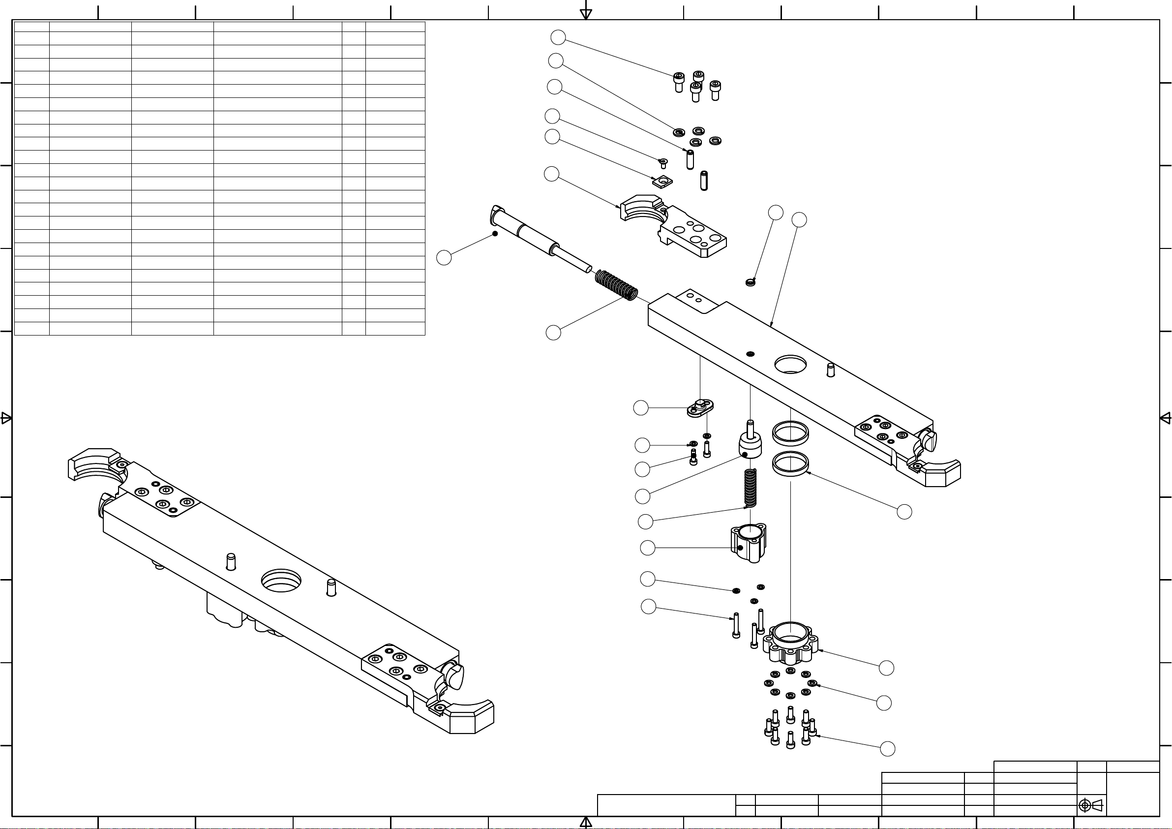
刀臂本體
扣刀爪
頂刀爪
頂刀爪彈簧
定位銷
銅套組
安全頂銷
頂刀爪限位鈑
安全頂銷彈簧
彈簧蓋鈑
迫緊環蓋
迫緊環CX0000d40D45
內六角承窩頭螺栓
內六角承窩頭螺栓
彈簧墊圈
內六角承窩頭螺栓
彈簧墊圈
內六角承窩頭螺栓
彈簧銷
內六角皿頭螺栓
彈簧墊圈
彈簧墊圈
10
TITLE-E
Main Body
Finger Spring
Key
Safety Cover
Position Limited Plate
Safety Spring Pin
Cox Cover
Seal
Ⅱ刮刷環Ⅱ
Hxagon Socket Heard Screw
Hxagon Socket Heard Screw
Spring Lock Washer
Spring Lock Washer
Hxagon Socket Heard Screw
Spring Pin
Socket Countersunk Heard Screw
Spring Lock Washer
Spring Lock Washer
9
QTY.
MATERIAL
AL70751
C50C2Gripper
S50C2Finger
2
2COPPER COVER
1
2Taper Snap Ring
2
6
8Hxagon Socket Heard Screw
8
8
2
SWPB
S45C2
S45C2
SMF50302
SWPB2
SS412Spring Cover
SCM4
4
8
4
4
6
8
3
7
19
18
20
21
5
2
4
6
5
13
1
4
3
2
1
F F
8
22
E E
14
7
12
9
D D
10
23
15
C C
11
B B
A A
DRAWING DESING CHECK APPROVE
wayne2014/3/5
NAME
5
4
12
11
10
deta INTERNATIONAL
9
8
7
TEL:886-4-256177 22 FAX:886-4-25617177
6
16
17
UNIT NO.
PART NO.
A40C-A2650111-01
MATERIAL
QUANTITY
SCALE
3
TITLE
#40刀臂組(R265)
Arm Assembly
2
NO.
圖框更新版本
2009/12/29
>0 ±0.1
>6 ±0.2
>30 ±0.3
>120 ±0.5
>350 ±0.8
>1000±1.2
1
Page 10
6
項目
1
A40C-0020A06
D D
OR00000P18VT2
OT000SER18VT3
5
零件表
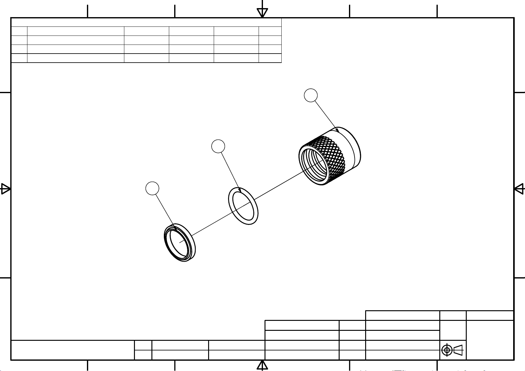
銅套
型環 P18
O
刮刷環 SER18
O-RING P18
SER18
4
青銅(銅鋁合金)
數量材質英文名稱中文名稱零件號碼
1
1NBR
1
3
1
2
1
C C
2
3
B B
MATERIAL
A A
deta INTERNATIONAL
TEL:886-4-25617722 FAX:886-4-25617177
6
NAME
5
DRAWING DESING CHECK APPROVE
doris2010/12/16
4
UNIT NO.
PART NO.
3
QUANTITY
SCALE
TITLE
銅套組
COPPER COVER00A40C-0020C
2
NO.
圖框更新版本
2009/12/29
>0 ±0.1
>6 ±0.2
>30 ±0.3
>120 ±0.5
>350 ±0.8
>1000±1.2
1
Page 11

2、Power Supply Specification for Electrical Control:
2-1. Follow the table listed below if disk type tool-changing
system’s power supply is not specified:
Power Supply
Category
Electrical Power Supply: 3
Specification
Signal Power Supply: DC 24V
Electrical Pneumatic
Phase
220V (50/60Hz)
5 BAR (Filtered
through three- points
assembly)
2-2. Specification of Sensor Used In disk Type Tool
Changer System Are as Followed:
Sensor
Specification
Tool Magazine Positioning
and Counting
M12 PNP 24V
Normal Open
Shielded Distance = 0.6mm
Tool-Changing Mechanism
Φ4 PNP DC24V
Normal Open
Shielded Distance =
0.8mm
5
Page 12

3、Electrical Control:
Configuration Drawing for Electronic Control
Components·····························································
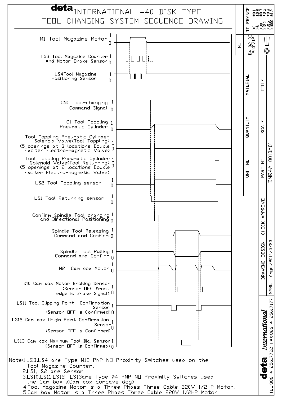
Sequence Drawing of Tool-Changing System··········
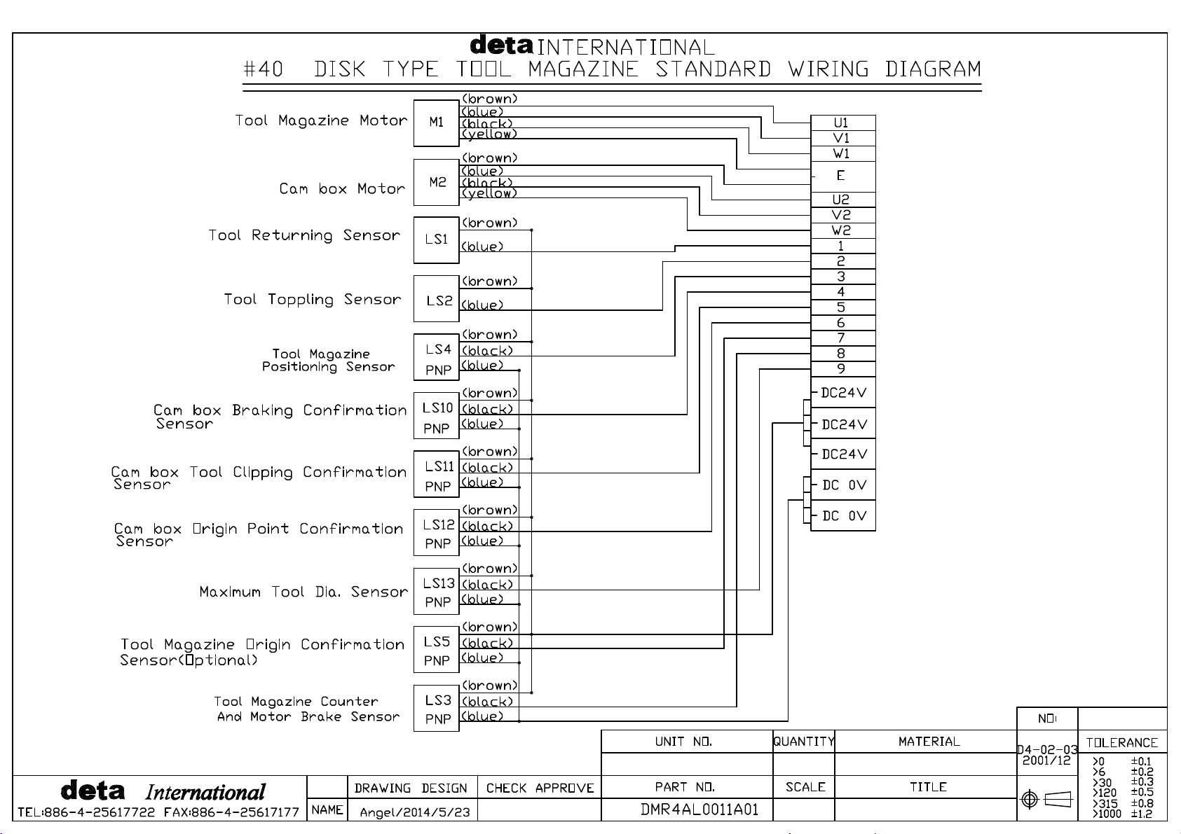
Standard Wiring Diagram·········································
Motor Wiring Diagram for Tool Magazine·················
Motor Wiring Diagram for CAM BOX························
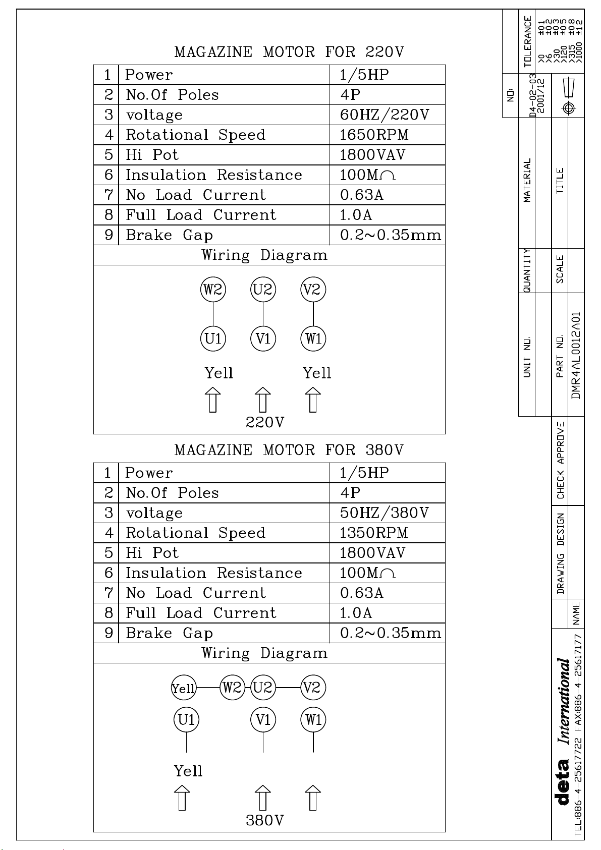
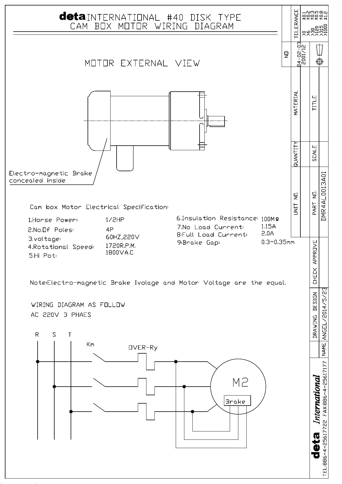
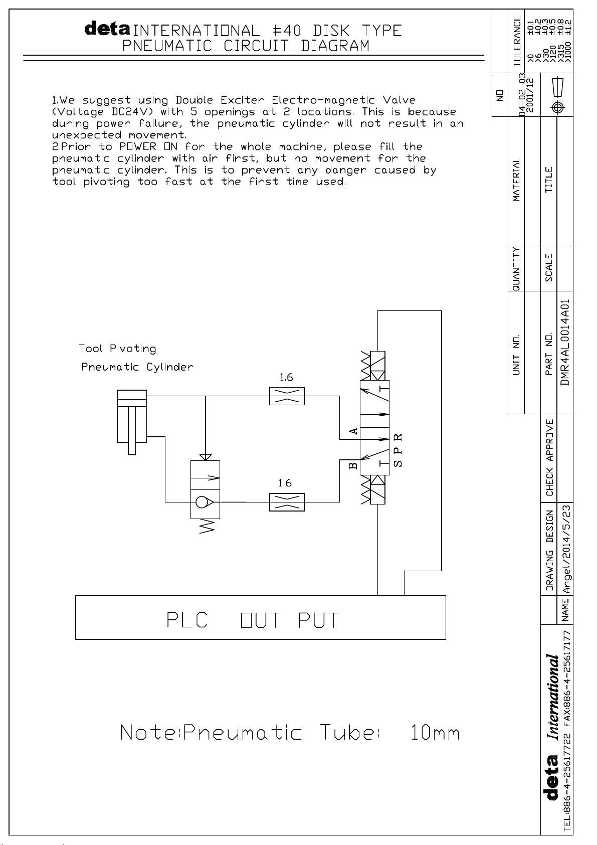
Pneumatic Circuit Diagram······································
DMR4L0009A01
DMR4L0010A01
DMR4L0011A01
DMR4L0012A01
DMR4L0013A01
DMR4L0014A01
6
Page 13
Page 14
Page 15
Page 16
Page 17
Page 18

4、Electrical Control Protection Programming:
(1) As Cam box and the tool magazine move extremely fast, the control
program for all motor relays, sensors, and the I/O port of
electromagnetic valves should be written on PLC Level 1 of the
controller (where SCAN TIME reacts faster). This is to prevent the
electronic control from having over slow reactions and causing the
machine to make wrong movements.
(2) In the proceeding of tool changing, each movement has to be
confirmed for its completion before continuing with the next
movement. (Refer to the tool-changing flowchart diagram)
(3) Do not topple the tool if the sensor for the positioning of the tool
magazine is not confirmed (i.e. LS4 is ON).
(4) Do not start the motor of the tool magazine or rotate the tool palette
if LS2 is OFF in the proceeding of tool tilt and LS1 is ON before
confirming the completion of tool tilt.
(5) Do not change the tool if tool tilt is not confirmed (i.e. LS1 is ON).
(6) Do not change the tool if the spindle of the machine has not returned
to the tool changing position.
(7) Do not change the tool if the spindle orientation has not been
completed.
(8) Do not move the spindle head if the arm has not return to its home
position.
(9) Overload protection relay should be activated when overloading, so
that the motor will not be burn off.
(10) The amperage of the motor’s current has to be below the motor’s
full load current.
1/4 Hp: 1.2 A; 1/2 Hp: 2 A; 3/4Hp:2.8 A;1 Hp: 3 A (at 60Hz)
7
Page 19
Page 20

5、Installation Procedure:
Before installing our disk type tool-changing system, you should read
this section carefully and understand it completely before proceeding
with the installation procedure.
Adjustment of the arm and the tool magazine was done before the
product left our factory, users do not have to spend time to work on it.
Hence, users could treat the tool magazine, the tool-changing
mechanism and the tool arm as a complete unit without having to do
any adjustment when installing our Disk Type Tool Changing System.
But the tool-changing point of the spindle and the tool-changing point of
the arm have to be accurately adjusted.
The tool-changing point of the spindle and the tool-changing point of the
arm have to be accurately overlapped, so that tool-changing
movements will be smoothly carried out under normal usage without
any collision noise. If the adjustment is inaccurate, not only toolchanging movements will not be smooth but it will also produce collision
noises, which will have harmful effect on the life span of the tool. Hence,
the only important point for installing our Disk Type Tool Changing
System is “to overlap the tool-changing point of the spindle and the toolchanging point of the arm accurately”. We recommend users to follow
the installation procedures below:
(1) Make an interfacing bracket as we have suggested, and lock it onto
the vertical column after confirming the bilateral perpendicularity
geometrical tolerance between the vertical column interface and the
tool magazine interface.
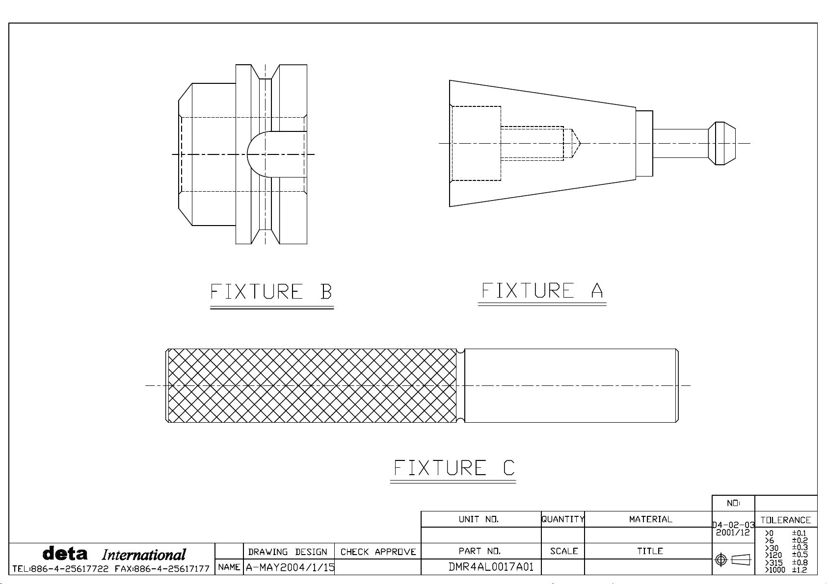
(2) Make a three-stages tool-calibration fixture as we have suggested.
(As per attached drawing)
(3) Lock the disk type tool-changing system onto the interfacing bracket.
Put the two rest blocks closely on the top of the interfacing bracket
and ensure the horizontal accuracy is kept.
(4) Move the Z-direction of the spindle to the highest point.
(5) Put adjustment fixture A into the spindle for the spindle to grip and
let the tool-changing arm grip adjustment fixture B. Press and
release the brake, which is on top of the tool-changing mechanism
motor. Then use a hexagonal spanner to turn the screw, which is
8
Page 21

located at the top center of the motor, until the tool-changing
mechanism reaches the tool-clipping position. (Keep turning the
screw on top of the tool-changing mechanism motor, and the toolchanging arm will remain fixed for a period of time. This will ensure
that the tool-clipping position has been reached).
(6) Use a level to adjust the interfacing bracket so that the tool-changing
arm is perpendicular to the spindle.
(7) Move the Z-direction of the spindle to about 2mm from the top of the
predicted tool-changing point.
(8) Adjust the X- and Y-direction of the tool-changing system so that the
X- and Y-coordinate of the tool-changing points for the tool-changing
arm and the spindle overlap. If adjusting the Fixture C allow it to
pass through the Fixture B and entering the internal hole of the
Fixture A that means the X and Y direction adjustment is completed.
(9) Measure the Z-direction coordinate for the tool-changing point of the
down to approximately 0.3~0.5mm above the Z-direction coordinate
of the tool-changing point for the tool-changing arm (the ideal
distance would be 1/2 of the spindle clamp distance). And set this
point as the coordinate for the tool-changing point. Again, use the
hexagonal spanner to turn the screw on the top center of the motor
in the opposite direction, until the tool-changing mechanism returns
to its home position.
(10) Change the tool manually first, to check that the movements of tool
pot toppling, the tool-changing mechanism performing the toolchange, the spindle catching and releasing tools, … etc coordinate
well together without any error, then proceed with CNC automatic
sequence program control. After trial tool-changing several times
and making sure that no bad phenomena appear, the positioning
pins can be fix into positions between the tool-changing system and
the interfacing bracket, and between the interfacing bracket and the
vertical column, respectively.
(11) Connect the circuit for electronic control, pneumatic valves, and
pneumatic source according to the wiring diagram.
(12) Pour the hi-grade of circulation oil into the tool-changing
mechanism until the surface of the oil can be seen from the oilviewing window
9
Page 22

6、Original Setting:
(1) The gap between the tool magazine orientation and the counter
sensor (M12) and the sensor block should be adjusted to between
0.8~1.0 mm.
(2) The gap of tool magazine motor’s brake pad should be adjusted to
between 0.2~0.35 mm.
(3) The gap between the sensor (Φ4) on Cam box tool-changing
mechanism and the sensing block should be adjusted to between
0.4~0.5 mm.
(4) The gap of Cam box motor’s brake pad should be adjusted to
between 0.3~0.35 mm.
10
Page 23

7、Troubleshooting:
7-1. Unstable tool tilting:
We have made the best adjustment to the disk type tool-changing
system before our product left our factory, and we would suggest
users not to do any random adjustment. If tool tilt is unstable due to
the transportation or human error, please follow the procedures below
to check and make adjustment:
(1) Check whether the pneumatic source conform to the power
supplying specification (refer to the section on the electrical
control’s power supply specification).
(2) Check whether the tool tilting mechanism has any damage to it. If
so, please contact us and we will send someone over to repair it.
※
Note: Be sure not to set the speed too fast, otherwise there is a
possible danger of dropping the tool.
11
Page 24
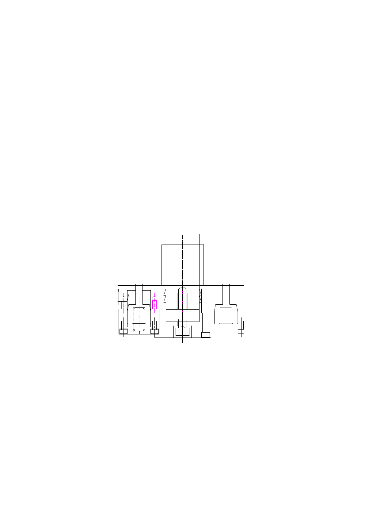
7-2. Tool Calibration Procedure
Please adjust the arm as following procedure when need:
(1) Use an overhead crane to lift the Cam box and inspect it externally
for any flaw.
(2) Use M12×50L + spring washer + flat washer to fasten the Cam box
onto the datum surface of the tool magazine’s main structure, and
pull the Cam box to the elongated holes on the outside.
(3) Open the power distribution box of the Cam box and connect it to
the power supply of the electronic control box. Check to see if
there is any abnormal phenomenon in the operation of the Cam
box.
(4) Tighten the nut and sun washer on the Cam box shaft。(as
illustrated in Diagram 1).
(5)Use M5×35L bolt + spring washer to fasten the packing rings on the
tool-changing arm, but do not tighten it temporarily.
(6) Sequentially insert the separation ring for the tool-changing arm
and put the tool-changing arm into the Cam box axis, and fasten
M12×35L bolt + spring washer onto the tool-changing arm with a
bit tightness around the axis and without any gaps.
(7) Supply electrical power to Cam box to allow the Cam box axis to
rotate to the tool-clipping angle.
(8) Use the three-point tool calibration fixtures to adjust the position of
the tool-changing arm. The adjustment method is to insert Fixture
12
Page 25
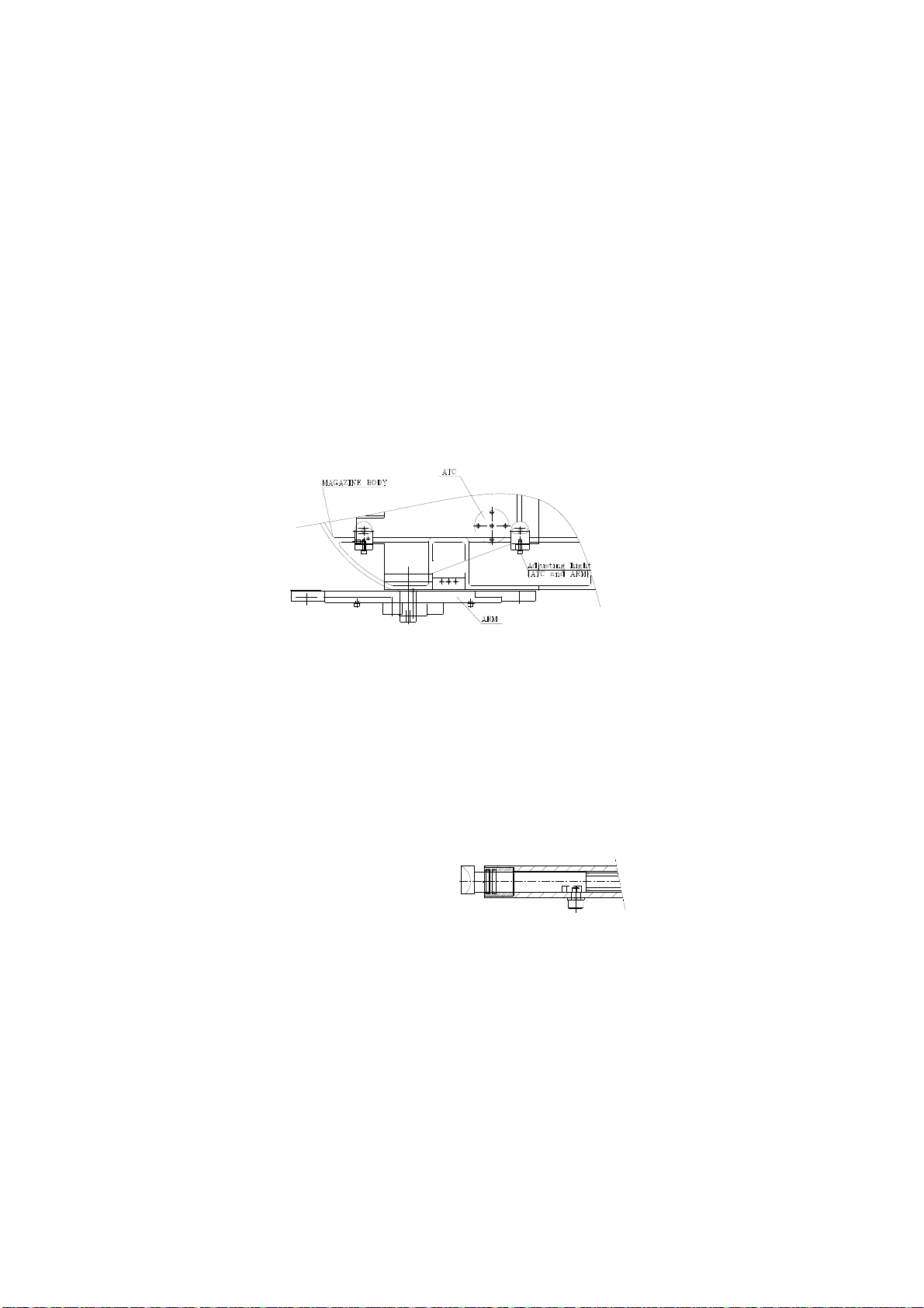
A into the tool pot, and Fixture B is placed at the tool clipper and
coupled with the protuberance, but the tool pusher clip has to be
placed into the arm first. Then, re-adjust the Cam box position, so
that Fixture C can go through Fixture A and Fixture B and reach
the arm at the position of the tool-clipping point, and line up with
the center of the tool pot.
(9) Tighten the Cam box on the magazine with 4.M12X12L screws。
(10) Check the clearance between the flange of the clip and tool
flange ,if the toper cleanses is equal to lower cleame are the
same。(the cleame is 0.8mm for BT and that is 0.2mm for CAT and
DIN Tool shank)if the toper cleame is not equal to lower clew , one
nut move the above set of Cam box and arm up or down。(as
illustrated in Diagram 2).
(11) In the process of tightening, use magnetic holder to hold the leveler
on the Cam box. The pointer of the leveler should touch the tool
clipper near the outer rim. Repeat the height measurement for both
ends of the tool clipper, where the height at both ends should be
within 0.1mm of difference.
(12) Place the tool pusher clip spring onto the end of the tool pusher clip,
and after smearing some lubricating oil, fit it into the tool-changing
arm. Fix M8 anti-revolving bolt + spring washer to the arm (as
illustrated in Diagram 3).
(13) Turn the manual bolt behind the Cam box motor, so that the tool-
changing arm descends about 50mm. Apply lubricant on the safety
pusher pin of the tool-changing arm and then insert it into the
lubricated spring of safety pusher pin. Then, insert the safety
pusher pin into the tool-changing arm and fasten it with M5×35L
bolt + spring washer (as illustrated in Diagram 1).
(14) After fastening the parts for the tool-changing arm, try several times
to make sure that the safety pusher pin can spring upwards freely,
and test to see if tool-changing movement is working properly by
putting a tool into the tool pot.
13
Page 26

7-3. When the tool palette not turning smoothly:
(1) Please check to see if there is any foreign object got stuck to the
Geneva wheel or drive shaft (refer to the assembly drawing and
part list). Please eliminate it.
(2) Please dismantle the motor and then electrify the motor, so it
operates independently. Check to see if it rotates smoothly without
any noise.
(3) If after going through above inspections without eliminating the
breakdown, please contact our company.
7-4. When the tool arm motion not smooth:
(1) Please check to see if there is any damage to the tool-changing
arm. If there is, please contact our company to have the parts
replaced.
(2) Please check the tool-changing mechanism and main structure of
the tool magazine to see if there is any change to the locking
position (Check to see whether there is any damage to the
positioning pin or it has already been shear off. If there is, please
contact our company to have the parts replaced.
(3) Please check whether there is any loose movement between the
tool-changing arm and axis of the tool-changing mechanism. If
there is, please stop the machine and cut off the power supply and
loosen the screw on top center of the motor with a hexagonal
spanner until the tool-changing mechanism reach the tool clipping
position. Push the tool-changing arm upward to the end and clip on
the tool that has toppled down, then calibrate both end of the toolchanging arm so they are within (0.1mm) in height, (Refer to tool
calibration procedure)
(4) Be sure not to self dismantle the tool-changing mechanism, if
there is any breakdown, please contact our company.
7-5 When the tool-changing speed is too slow:
(1) Please check whether the motor produces any strange noise
(2) Please check whether the power supply conform to the
specification.
14
Page 27

(3) Please check whether the speed of spindle clamping and
unclamping complies with the requirement.
(4) There is any other breakdown, please contact us.
7-6. Sudden power failure during the course of tool change by
the tool-changing arm
(1) For short period of power failure, please re-start the machine, and
manually return the tool-changing arm to its original position.
(2) For long period of power failure, please release the motor brake,
rotating the tool-changing arm to its original point location by using
a spanner to turn the spindle on top of the Cam box motor, and
ensure the safety of the machinery by forcing the tool pot to return
the tool.
15
Page 28

8、Maintenance:
(1) The circulation oil inside the tool-changing mechanism should be
changed after 2400 hours of continuous usage. And the oil level
has to be checked non-periodically. A refill is in order if the oil falls
below the required level.
(2) Tool disk and cylinder mounting plate’s surface need to cheek
grease everymonth
(3) Check and see if there is still some lubricating oil in the bearing
every three-month.
16
Page 29

Thank you for using our products. Please inform us if there is any defect
so that we can make improvements and offer you more stable and better
quality products.
deta
INTERNATIONAL
No. 47-5, Zunqian Rd., Shengang Shiang,Taichung
County 42952 Taiwan(R.O.C)
Tel: (886-4) 2561-7722
Fax: (886-4) 2561-7177
Sales department e-mail [email protected]
Design department e-mail [email protected]
17
Page 30

Automatic Tool Changer
S402
<< Manual >>
Sun-Train Cam Industrial Co., Ltd.
Page 31

Catalog
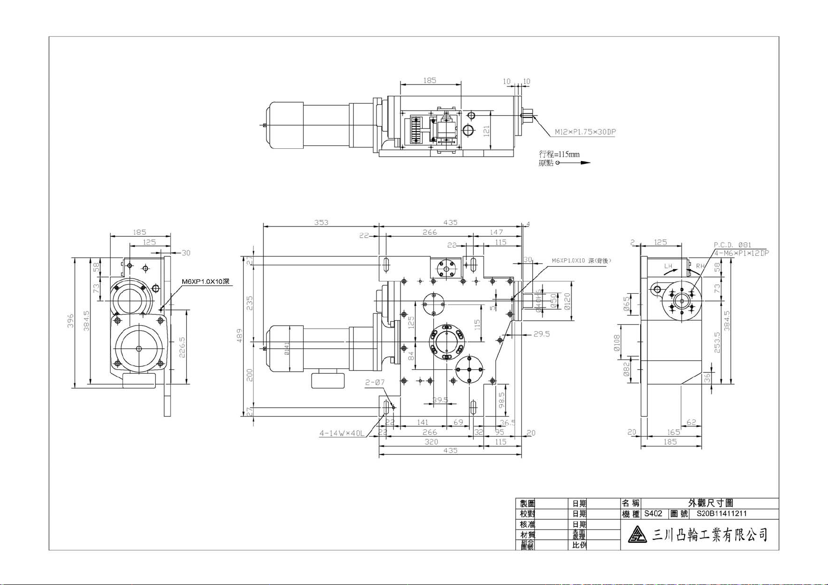
1. external dimension diagram-------------3 6. signal wiring methods -------------------13
2. articles list-------------------------4 7. the installation direction of eccentric cap------14
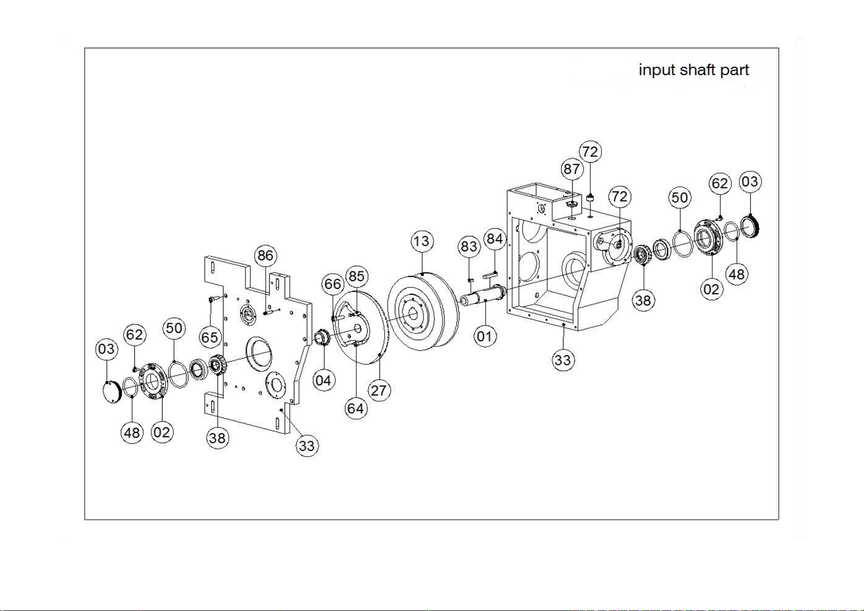
3. exploded diagram 8. adjustment method of cam and bearing pre-load -15
3-1. input shaft part-------------------6 9. adjustment method of tool arm-------------16
3-2. output shaft part------------------7 10. specification of lubricant oil ---------------17
3-3. swing arm part -------------------8 11. ATC brake motors----------------------18
3-4. signal part ----------------------9
4. dismantling steps-------------------10
5. timing diagram---------------------11
2
Page 32
Page 33

Article List
items dash number name dash number items dash number name dash number items dash number name dash number
01 S402A01ST-01
02 S402A01ST-02
03 S402A01ST-03
04 S402A01ST-04
05 S402B01ST-01
06 S402B01ST-02
07 S402B01ST-03
08 S402B01ST-04
09 S402B01ST-05
10 S402B01ST-06
11 S402B01ST-07
12 S402B01ST-08
13 S402C01-65L-L-P3
S402C02-80L-L-P3
14 S402D01ST-01
15 S402D01ST-02
cam axis
eccentric cap
eccentric cap nut
chain gear
6-spline shaft
6-groove tube beads
driving wheel
front bracket
bracket of tube beads
tube beads fixity cover
spacer of tube beads
spacer
cam65 degrees
cam80 degrees
swing arm
swing axis
1 24 S402E01ST-01
2 25 S402E01ST-01
2 26 S402F01ST-01
1 27 S402F01ST-02
1 28 S402F01ST-03
1 29 S402F01ST-04
1 30 S402J01ST-01
1 31 S402J01ST-02
1 32 S402J01ST-03
1 33 S402K01ST-01
1 34 DA20X28X13
1 35 DA22X34X11
1 36 DB24X45X13
37 B0080305 6202ZZ/deep groove ball bearing 2 61 68010019
1 38 B1150102 HR30206/滾錐軸承 2 62 68010020
1 39 B1170102 HR32008/滾錐軸承 2 63 68010021
signal standard film
dust cover
motor fixity
bevel
bevel pinion
eccentric sleeve of motor
chain gear (ideal gear)
hain wheel axis
chain wheel outer cover
bulk box
needle roller bearing∮20
needle roller bearing∮22
needle roller bearing (powerful type)∮24
1 48 68010005
1 49 68010007
1 50 68010008
1 51 68010009
1 52 68010010
1 53 68010011
1 54 68010012
1 55 68010013
1 56 68010014
1 57 68010015
6 58 68010016
1 59 68010017
1 60 68010018
55*2/
O-ring
G50/
O-ring
G75/
O-ring
G80/
O-ring
G95/
O-ring
AN08
locknuts
AW08
lock washer
AN11
locknuts
AW11
lock washer
M4*8L/hex socket head cap screws
M4*10L/ hex socket head cap screws
M4*12L/ hex socket head cap screws
M5*16L/ hex socket head cap screws
M6*14L/ hex socket head cap screws
M6*16L/ hex socket head cap screws
M6*25L/ hex socket head cap screws
2
1
2
1
1
2
2
1
1
2
8
10
2
4
17
6
16 S402D01ST-03
17 S402E01ST-01
18 S402E01ST-02
19 S402E01ST-01
20 S402E01ST-01
21 Na Na 45 Na Na
22 S402E01ST-06
23 S402E01ST-01
swing arm fixing base
brake signals wheel
cam signals wheel
signals fixity
signals wheel axis
signal box side cover
signal axis chain wheel
1 40 B1190102 HR32011/滾錐軸承 2 64 68010022
1 41 CBC80012
1 42 CBC81012 AS4065/needle bearing spacer 4 66 68010024 M8*35L/ hex socket head cap screws 2
1 43 68010001
1 44 S402L01ST-01
1 46 68010003
1 47 68010004
NTB4065/
HK3516/
needle bearing
needle bearing
self-lubricated bearing
40*52*8/
UHS50/
TC grease seal
U- grease seal
2 65 68010023
1
1
1
1
4
M8*20L/ hex socket head cap screws
M8*25L/ hex socket head cap screws
7
13
Page 34

Article List
items dash number name dash number items dash number name dash number items dash number name dash number
67 68010025
68 68010026
69 68010027
70 68010028
71 68010029
72 68010030
73 68010031
74 68010032
75 68010033
76 68010034
77 68010035
78 68010036
79 68010037
80 68010038
81 68010039
82 68010040 4*4*10/ double head round keys 1
M10*20L/ hex socket head cap screws
M10*30L/ hex socket head cap screws
M4*8L/
flat head screw
M5*8L/
flat head screw
PT1/8"*8/
PT1/2"*12/
M5*5L/
M5*10L/
M6*8L/
∮6/
∮10/
M10*P1.25/
M12/
ST-W12/
25H*92L
oil dam
oil dam
socket set screws
socket set screws
socket set screws
spring washer
spring washer
slip-on lock nut
galvanized nut
axis tab
chain
4 90 FM2207508220 motor_3/4HP_1:8_AC220V 1
4 91 FM2207508380 motor_3/4HP_1:8_AC380V 1
1
4
1
4
2
4
8
4
4
1
1
1
1
83 68010041 5*5*20/ double head round keys 1
84 68010042 10*8*55/ double head round keys 1
85 68010043 8*30L/pin 2
86 68010044
87 68010045
88 68010046 Proximity switch
89 68010047
8*40L(1/50)/牙 M6
28mm
oil lens
PNP-3/E2E-CR8B1
MG16A-10B/
angle pin
cable fixed head
3
1
1
1
5
Page 35
6
Page 36
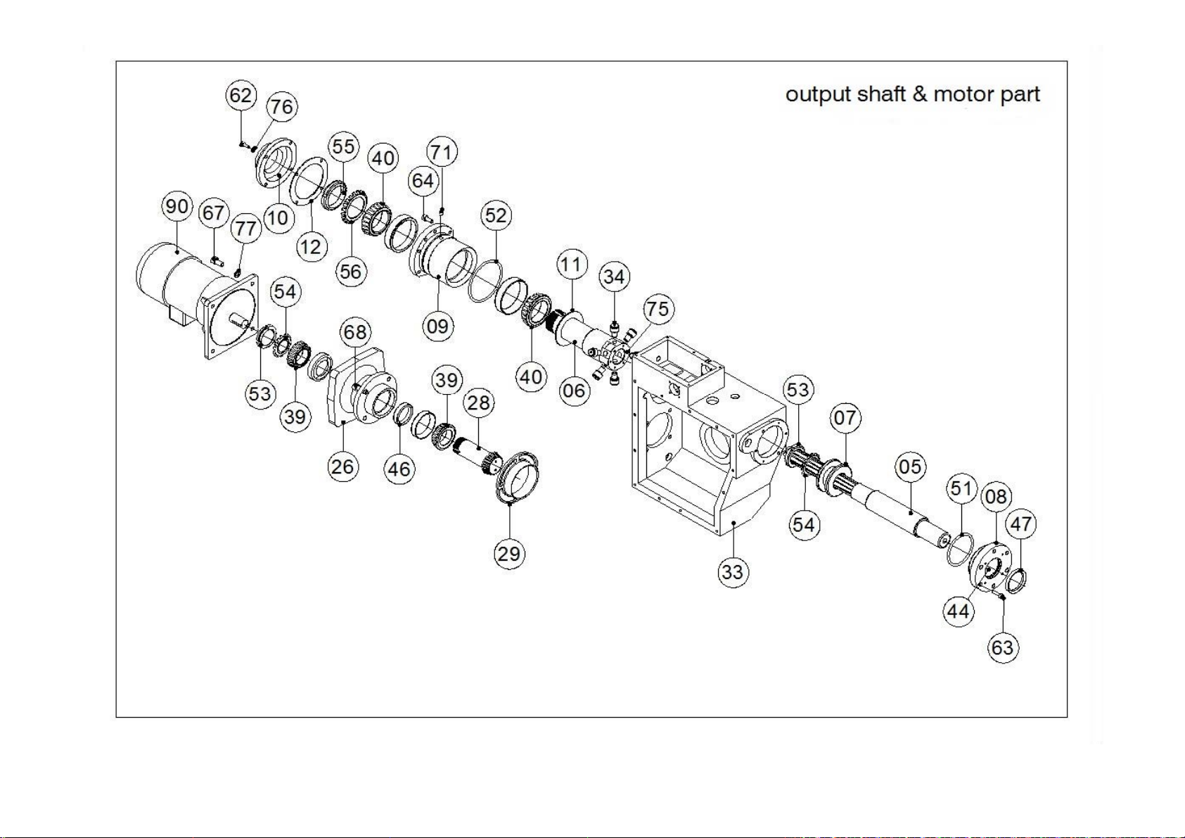
7
Page 37
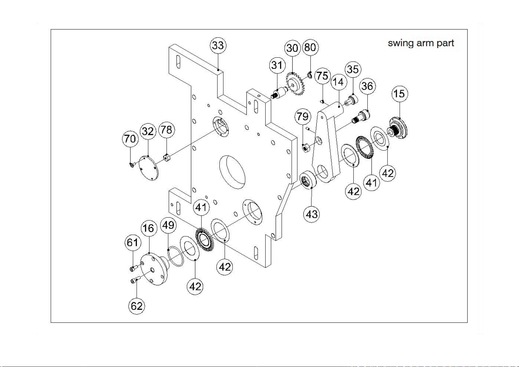
8
Page 38
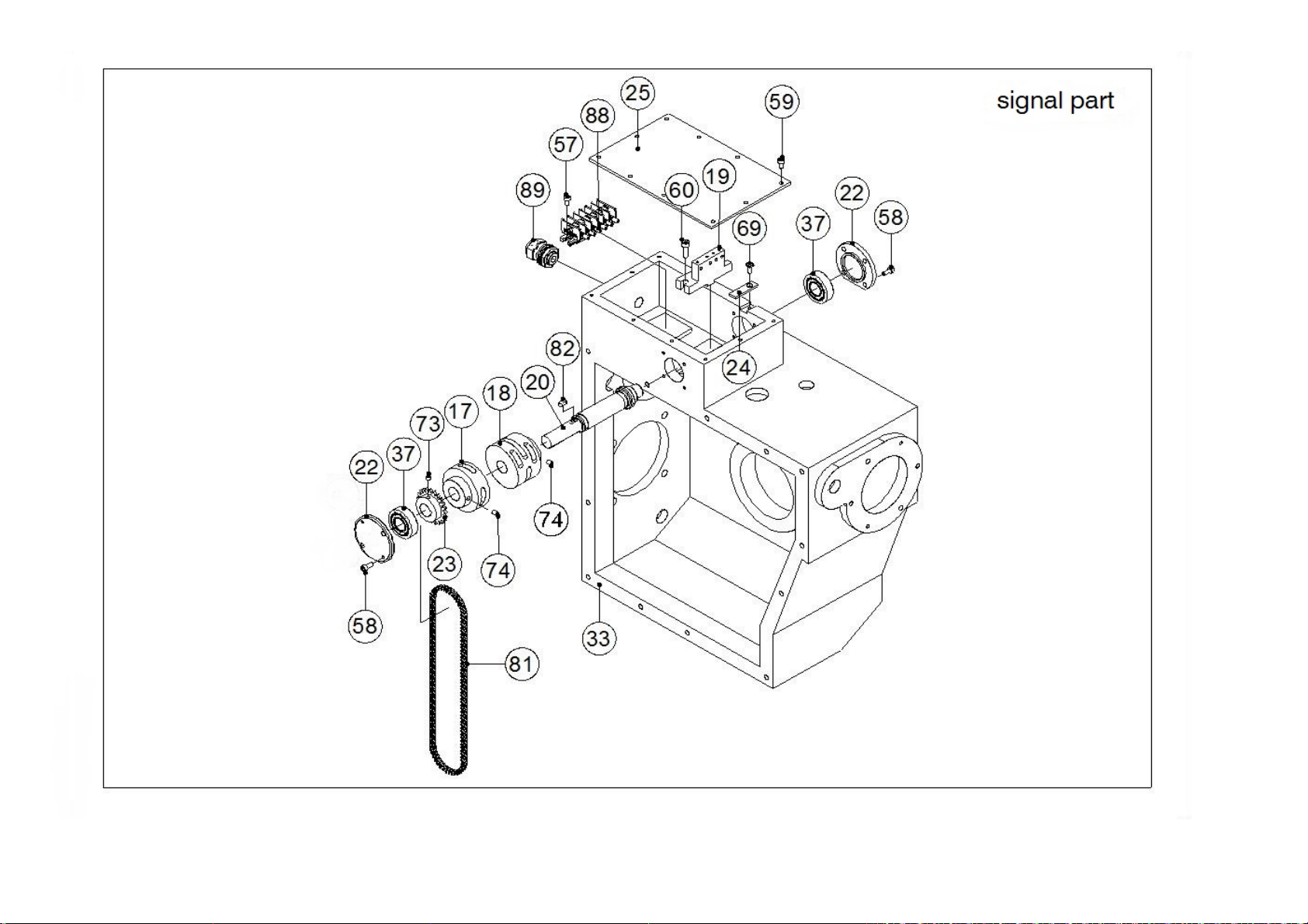
9
Page 39

Dismantling Steps:
First: The steps to replace 6-spline shaft:
1 Rotate to origin point and dismantle taper pin 【86】and M8 nut【65】 in which located above bulk cover. Next, remove the bulk cover.
2 Loosen the M6 bolts【63】and dismantle former fixing set【08】
3 Remove the 6-spline shaft 【08】 and dismantle driving wheel 【07】、locknuts AN08【53】and locknuts spacer AW08【54】and replace
with a brand-new 6-spline shaft.
★Reverse the steps for assembly and restoration.
Second: The steps to replace the bearing in which located above 6- grooves tube beads:
1 Rotate to origin point and remove taper pin【86】and M8 nut【65】in which located above bulk cover. Next, remove the bulk cover.
2 Turn around the 6-groove tube beads【06】and remove former fixity【08】
3 Loosen and replace M6 socket head cap screws in which located inside the bearing 【75】
4 With a special dismantling tool to remove needle roller bearingφ20【34】and install the new articles, and then fix M6 allen screw with
anaerobic adhesive.
★Reverse the steps for assembly and restoration
Third: The Steps to Replace Swing Arm Bearing
1 Rotate to origin point and remove taper pin【86】and M8 nut【65】 in which located above bulk cover. Next, remove the bulk cover.
2 Remove allen screw【61】from swing arm fixity.
3 Use dismantling tools to twist swing-arm fixed axis【15】and then take it out.
4 Remove needle bearing axis NTB4060【41】, needle bearing spacer AS4060【42】and needle bearing HK3516【43】.
5 Remove needle roller bearingφ22【35】and needle roller bearingφ24【36】and replace all needed articles.
★Reverse the steps for assembly and restoration.
10
Page 40
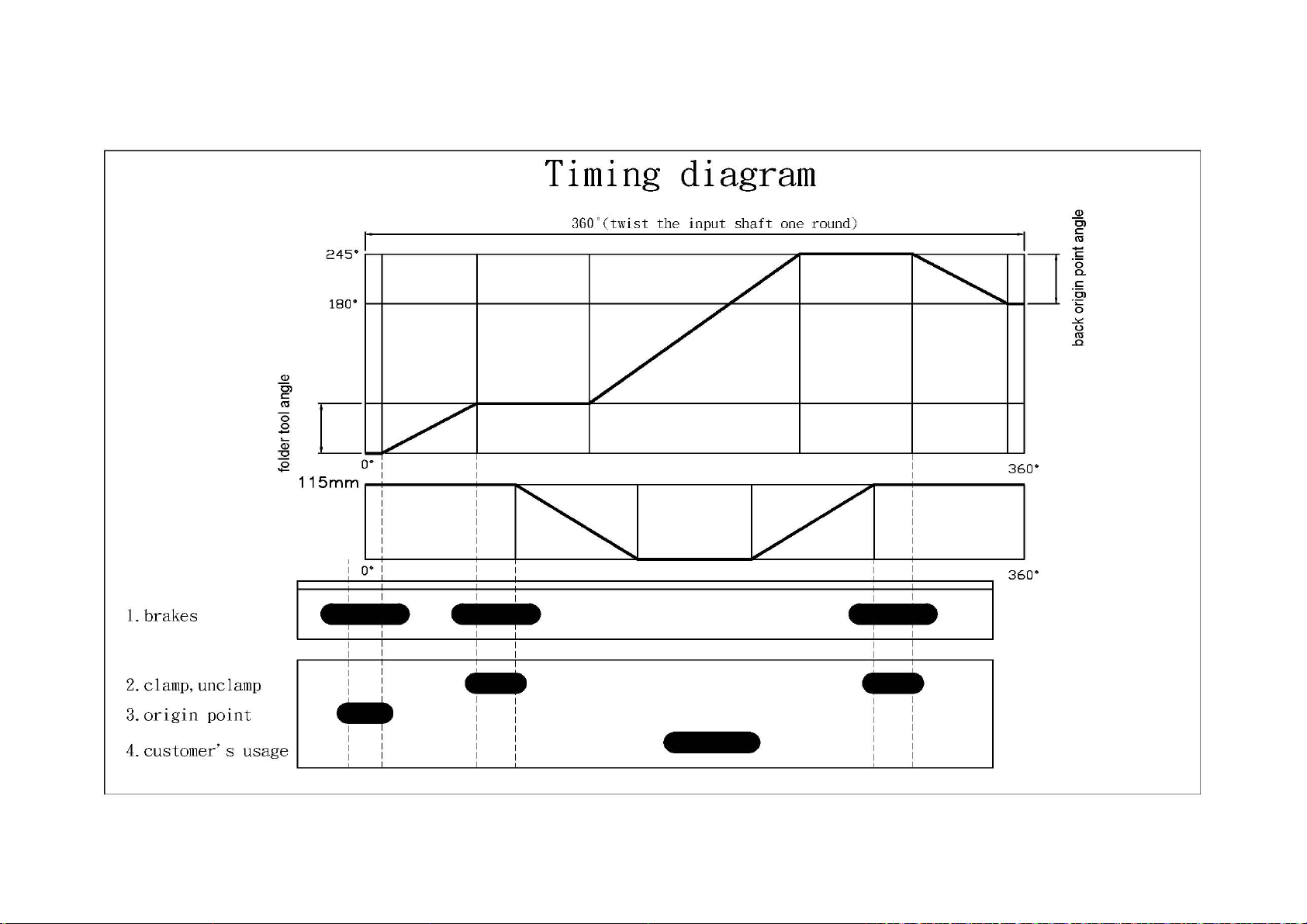
11
Page 41
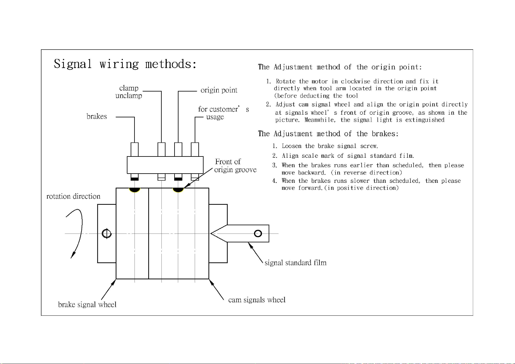
12
Page 42
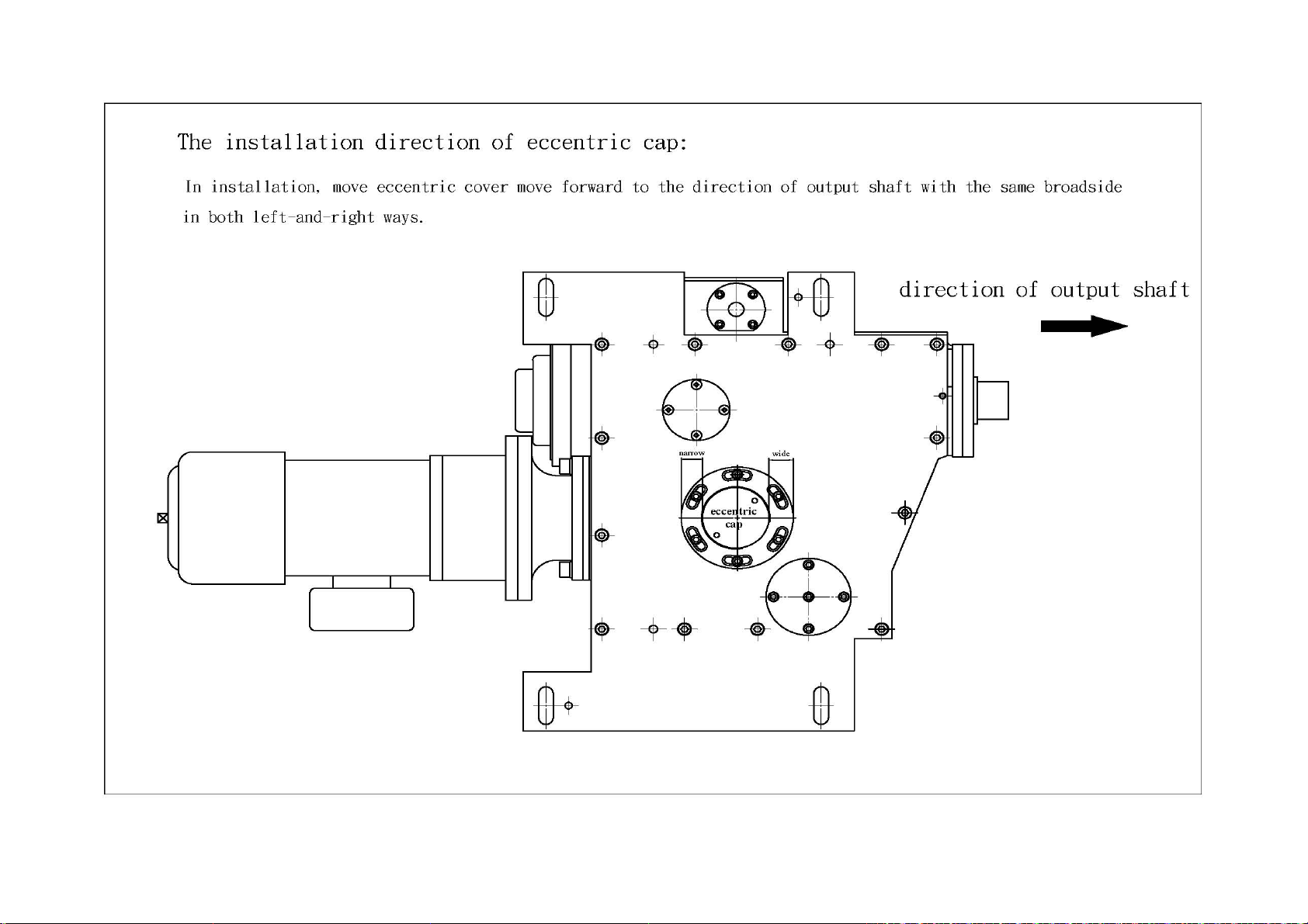
13
Page 43
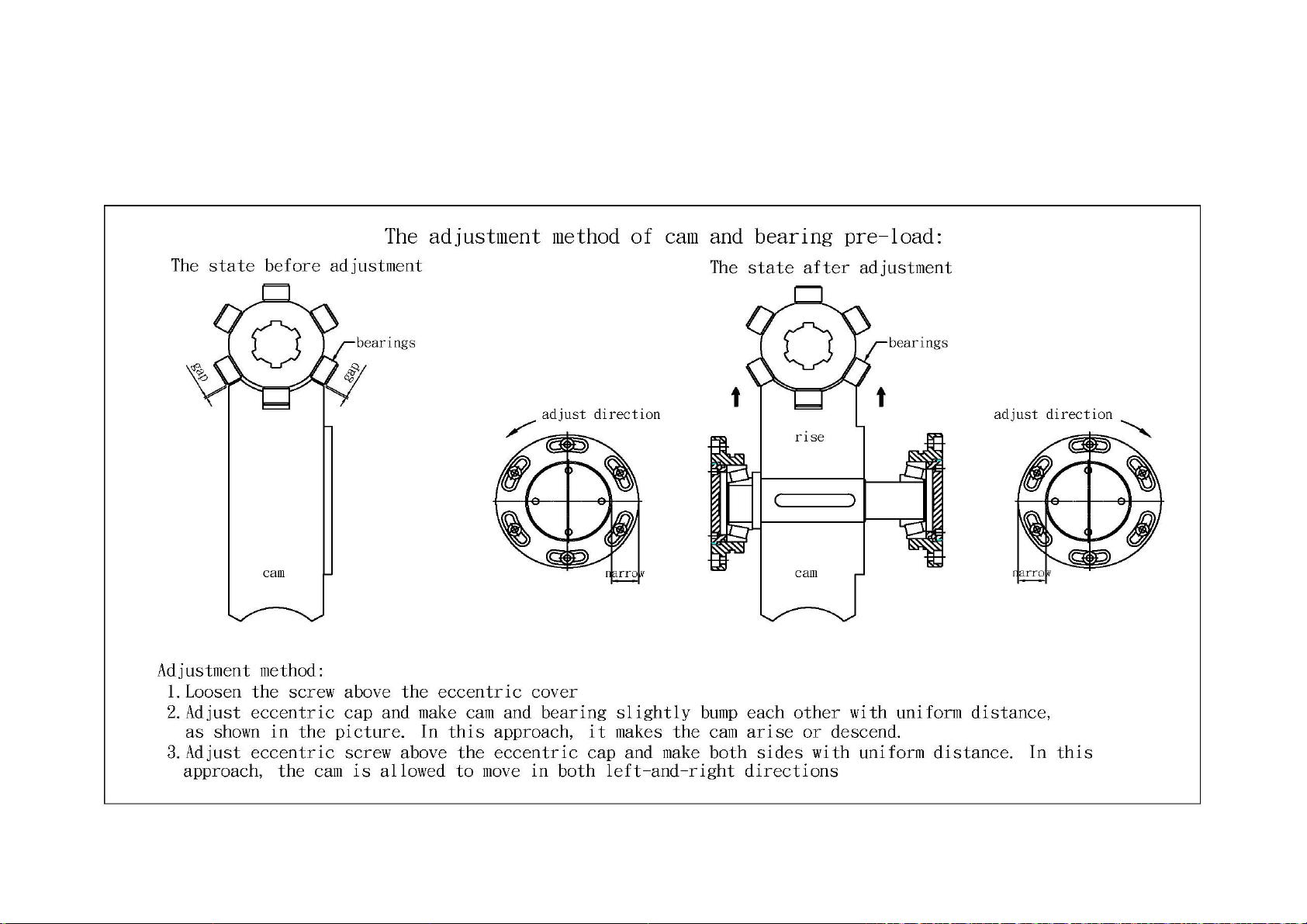
14
Page 44
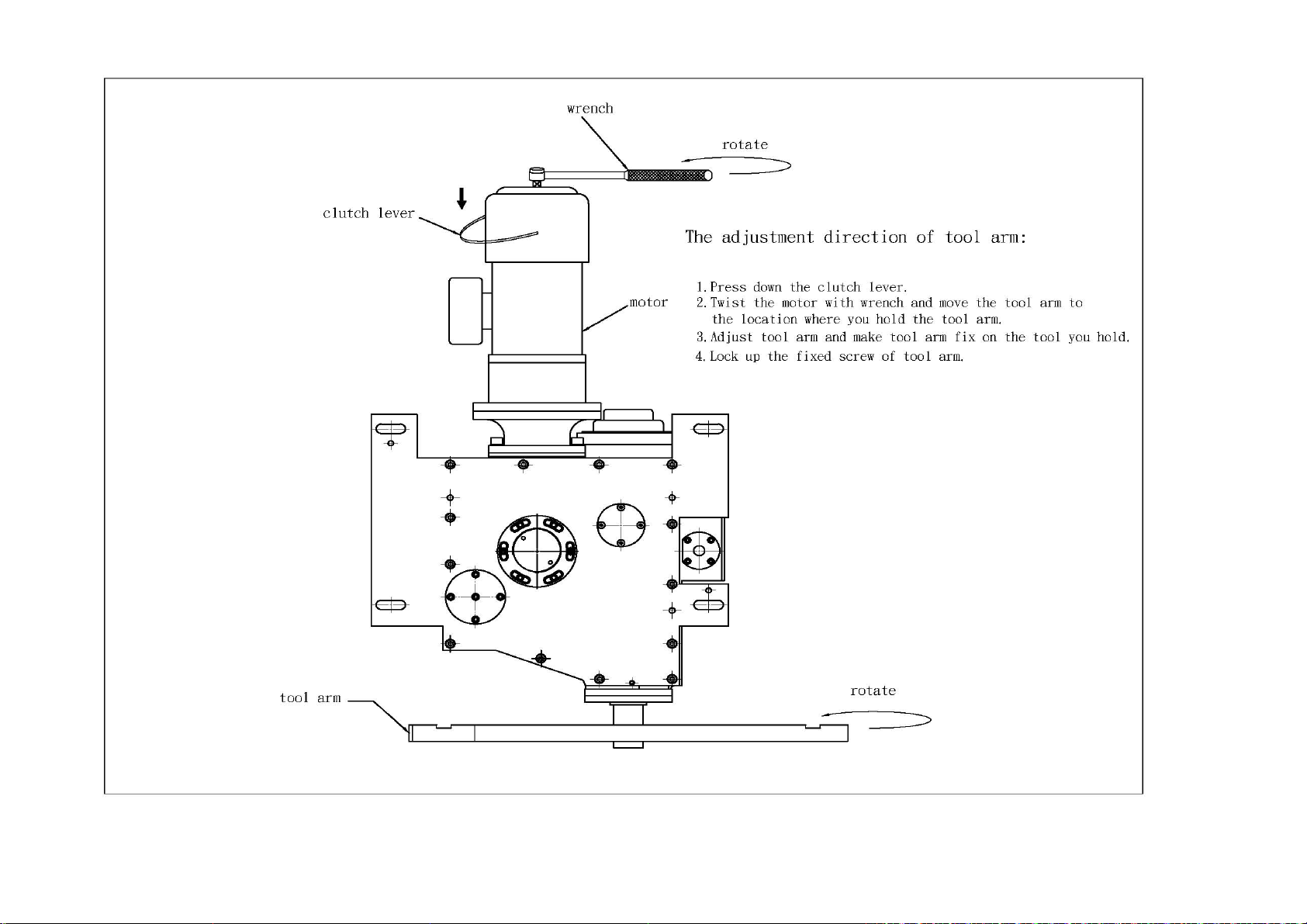
15
Page 45
The speculation of lubricant oil
brand viscosity index ISO VG
SHEEL Omala EP 150~220
TOTAL Garter EP 150~220
MOBIL Mobilgerar 150~220
ESSO Spartan EP 150~220
CAST-OL Alpha SP-EP 150~220
CPC Pleiotropic gear oil 85w/95
A. Note:
1.Do not use recycled oil inside the machine, you must add lubricant oil to clean it.
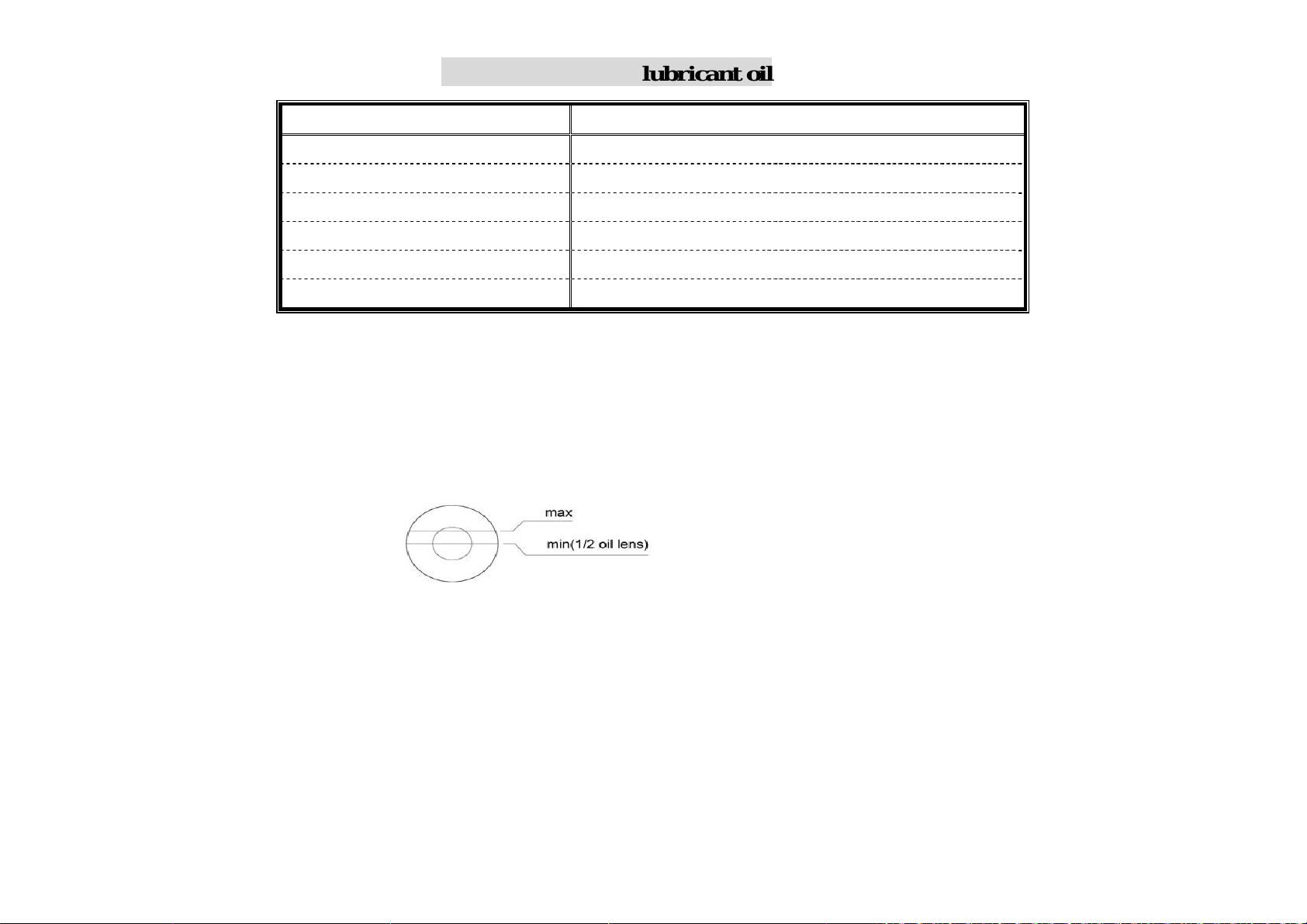
2.The lubricant oil must add up to at least half of oil immersion lens, roughly 4200cc fuel.
B. Operating hours:
You must replace lubricating oil after the machine runs repeatedly 2400 hours.
C. Maintenance:
1.You muck check the oil level before you turn it on and add sufficient oil.
2.The lubricating oil should keep appropriate viscosity.
3. The voltage wiring used for motor should be correct.
16
Page 46

ATC motor:
A. The checking points before you use it:
(1) Check if the power cord is properly installed.
(2) When a motor starts, please pay attention to its braking action
B. Checking troubleshooting steps:
(1) Check if the power cable fully furnished, whether the voltage is stable or not and check the electromagnetic switches too.
(2) When a motor starts, check if the braking action reacts to it. If the braking action fails, it will cause motor overload or burning.
(3) Check whether the motor burned or not.
(4) Check the brakes: (a) Check if the rectifier is burned (b) Check if the brake coil is burned.
17
 Loading...