

LED Bulkhead
L1011WH
8W Standard, white - 270mm
LED Bulkhead
L1011CH
8W Standard, chrome - 270mm
LED Bulkhead
L1021WH
14W Standard, white - 330mm
LED Bulkhead
L1021CH
14W Standard, chrome - 330mm
LED Bulkhead
L1022WH
14W Std + microwave, white - 330mm
LED Bulkhead
L1022CH
14W Std + microwave, chrome - 330mm
LED Bulkhead
L1023WH
14W Emergency, white - 330mm
LED Bulkhead
L1023CH
14W Emergency, chrome - 330mm
Stratus
Features
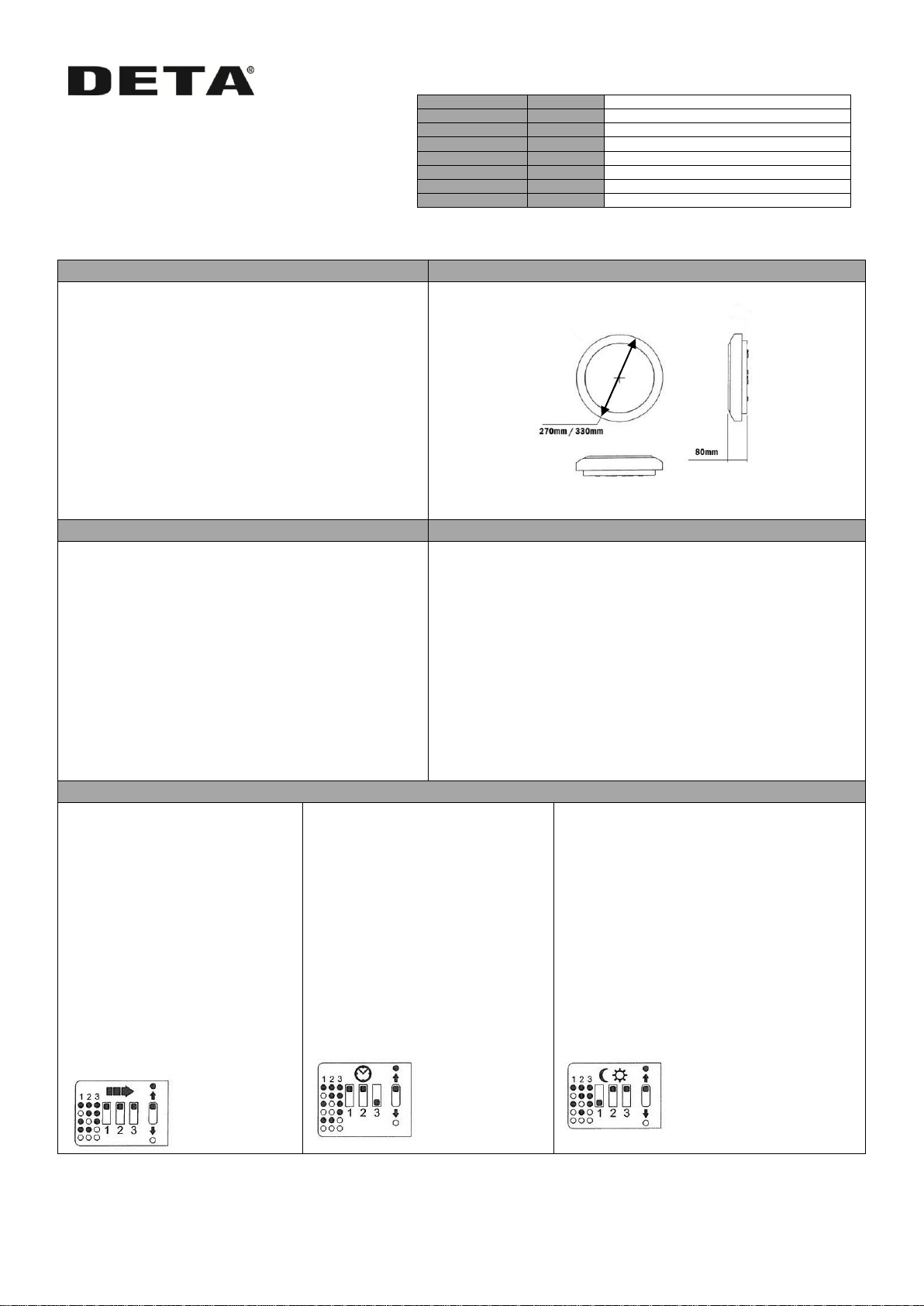
Dimensions
Small 8W option available, only 270mm diameter
Standard 14W 330mm diameter
Optional Chrome finish
Elegant clean lines with smooth finish
Slim profile
Emergency option available
Tough Polycarbonate diffuser
Tough polycarbonate body
Microwave sensor for reliable detection
Instant illumination
Low Power consumption
Rated at IP65 suitable for bathrooms
Safety Information
Environmental
• This product is intended for indoor use only
• It is recommended that luminaires are installed and
fitted by a qualified electrician ensuring the installation
complies with the current IEE wiring regulations.
• These instructions should be read carefully and retained
after installation for future reference and maintenance.
• Always ensure there is adequate free air ventilation
around the luminaire at all times.
• Do not install this product on newly plastered surfaces.
• Ensure all electrical connections are secure and that
there are no loose strands.
• This product is NOT dimmable
• This is a Class 1 product and MUST be earthed.
This product may contain substances that can be hazardous to the
environment if not disposed of properly. Electrical and electronic
equipment should never be disposed of with general household waste
but must be separated for its correct treatment and recovery. Where
possible recycle your packaging
Operation – Microwave Sensor (where fitted)
Detection Range:
This determines the effective range of
the motion detector and is set by DIP
switches on the sensor itself, refer to
figure. Note that reducing the
sensitivity will narrow the detection
range. The following setting are
available:
i. Maximum up to 5m
ii. Range up to 3.5m
iii. Range up to 2m
iv. Range up to 1.5m
v. Range up to 1m
Hold Time:
This determines the time the fitting
remains at 100% level after motion is last
detected and is set with DIP switches at
the sensor itself, refer to figure. The walk
test setting is useful when installing the
fitting to establish correct operation and
range.
The following settings are available:
i. walk test mode
ii. 30s
iii. 3 minutes
iv. 5 minutes
v. 15 minutes
vi. 25 minutes
Daylight Sensor:
This setting holds off the 100% light output should
there be sufficient daylight and is set using DIP
switches at the sensor, refer to figure. The
following settings are available:
i. 2 lux darkness only
ii. 5 lux darkness only
iii. 20 lux twilight
iv. 30 lux twilight
v. *daylight, photocell disabled.
*In daylight setting the lamps will always
be on with motion detection and operate
at 100% light output, even in bright
daylight.

Installation
SUGGESTED METHOD OF INSTALLATION
Read instructions and check you have all the tools and
accessories to complete the installation safely and in
compliance with current electrical standards.
STEP 1
Isolate the mains supply before connecting. Unpack the
luminaire. Ensure there are no obstructions or services in the
way.
STEP 2
Remove the diffuser and decorative rim from the base by
turning 45 anti-clockwise and pulling away from the base
STEP 3
Loosen but do not remove the gear tray retaining screws.
Adjust the position of the gear tray to align the hole in the
keyhole slots with the retaining screws, and remove the gear
tray from the base.
STEP 4
Select a suitable cable entry point in the body of the luminaire
and feed the mains cable through the grommet to prevent
damage to the cable.
STEP 5
Position and fix the base of the bulkhead to a suitable solid
surface. a) drill holes. b) fit rawl plugs. c) fix into position
with screws supplied
STEP 6
Terminate the cables into the terminal block mounted on the
underside of the LED board ensuring the correct polarity is
observed and the luminaire is fully earthed. Ensure all
conductors are fully sleeved and insulated (for emergency
lighting see additional information below)
STEP 7
Dress any cables away from the edge of the luminaire. A)
replace the gear tray and secure in position. B) replace the
diffuser.
STEP 8
Turn on the mains power supply and test the luminaire for
correct operation.
Additional Wiring Details (Emergency Products Only)
Extractor Fan “switching”
Ensure the luminaire has a continuous live supply to “L1” (un-switched
live). The “maintained” emergency luminaire can be switched via
connection “L” (switched supply).
Ensure the battery cells are connected
Units fitted with the microwave sensor also have an
additional terminal that will allow the control of a “timed”
extractor fan.
Note: a Three Pole Fan Isolator must be fitted.
Voltage
230 Volt 50Hz
Ingress Protection
IP65
Rated Wattage: Small
8W (L1011WH/CH)
Rated Wattage: Large
14W
Lamp Type:
Integrated LEDs
Colour Temp
4000k
NPD0507v3 24 June 2015 Tel; +44 (0)1582 544 544 Technical Helpline: +44(0)1582 544 548
DETA Electrical Company Limited
Kingsway House, Laporte Way
Luton, Bedfordshire. LU4 8RJ UK
 Loading...