

Page 1
1g Wireless Switch
9521###
2g Wireless Switch
9522###
Wireless Scene Setter
9525###
Wireless On/Off/Stop Switch
9738
Connect
Features
Deta Connect Wireless Switches can be paired with Deta Connect
Master Dimmers and Deta Connect Sockets to give remote switching of
the device.
Wireless Switches can also be paired with Inline Dimmers and Relays to
solve difficult installations and reduce cabling.
When Wireless Switches are paired with Master Dimmers or Inline
Dimmers, they can turn the light on, off and adjust the light level.
If the Wireless Switches are paired with socket outlets or relays, they
will switch the socket or relay on remotely.
One Wireless Switch can be paired with multiple devices
Wireless switches are battery operated, they can be installed
anywhere – there is no need for cabling or a back box.
It is important to install this product in accordance with the fitting
instructions below. Failure to do so may render your guarantee void.
Installation
Set-up / Linking Products
Wireless Switches and scene setter installation as follows:
Linking a Connect device (Master Dimmer, Socket or Inline device) to a
Connect Wireless Control
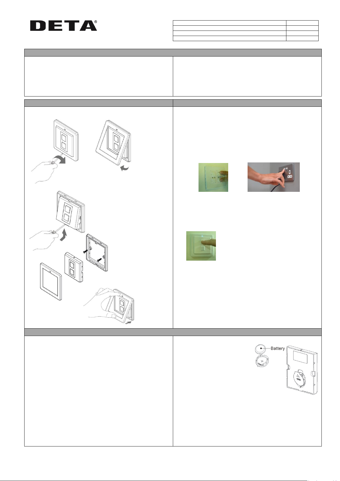
1. Place the Connect device that you wish to control in ‘linking’ mode. For
information on how to do this please refer to the instruction manual
for that specific Connect device.
Master Dimmer - press and hold both buttons simultaneously –
the blue and amber LED’s will flash alternately to signify linking
mode, and then release them.
Socket Outlet - press and hold the button until the blue and
amber LED’s will flash alternately to signify linking mode, and
then release them.
2. Press a button on the device to be “linked” and the Blue LED will flash
quickly to signify that the dimmer is now linked.
The indicator light on the device you are pairing to
will flash to confirm that the Wireless Control is now
linked. This process can be repeated to control
multiple Connect devices from one Wireless Control.
Unlinking the Switch from a Connect device
This will remove all wirelessly connected controls
1. Place the Connect device that you wish to remove in ‘linking’ mode.
For information on how to do this please refer to the instruction
manual for that specific Connect device.
2. Whilst the Connect device is in Linking Mode, tap a button on the
Wireless Control. The LED light on the target device will flash to
confirm that the Switch and device are unlinked.
Important things to consider
Changing the Battery
Signal Range
• Reliable range of operation is approximately 15 metres indoors and up
to 100m outdoors using the Connect Link/WiFi-Link. This figure may
vary depending upon the environment; very thick walls, bodies of
water or large metal objects may interfere with radio range.
• If the distance between the transmitter and receiver is too great to
achieve reliable operation, the Connect Signal Booster may be used in
conjunction with this product to increase the range.
A battery will last for typically 2 years.
When the battery voltage is low the
transmission level is low and is
indicated by the blue LED not staying
on as long as normal.
Battery Type: CR2032 3V Lithium Battery
1. Remove the front plate – see Installation
2. Remove the Wireless module.
3. Remove the battery cover and replace the battery, ensuring the
polarity is correct.
4. Re-assemble in reverse order.
Notes:
Do not recharge
Please dispose of used
batteries responsibly
Keep away from children
Do not swallow (If swallowed, seek medical
advice immediately)
1. Remove front cover by inserting
screwdriver into slot at bottom and twisting
5. Reattach the
front plate
3. Attached the frame to
the back box (if used) or
directly to the wall using
the fixing screws
supplied
4. Clip Wireless module
into the frame
2. Remove wireless module, by
using a screwdriver to lever the
module from the frame
Page 2
1g Wireless Switch
9521###
2g Wireless Switch
9522###
Wireless Scene Setter
9525###
Wireless On/Off/Stop Switch
9738
Connect
Mood/Scene Switch
ON / OFF / STOP Switch
Linking
The Scene Setter can link with Master Dimmers and Socket Outlets. To link,
put the device you want to link with in linking mode (see Set-up / Linking
Products above), then press the large ON or OFF button on the scene setter.
The blue LED on the device you are linking with will flash.
Setting up a Scene
1. Firstly set the desired status of each linked receiver i.e. on or off, or the
desired dim level of any dimmable receivers to be included in the
scene.
2. Select which scene button (1, 2, or 3) is to be used to save and recall
the new scene.
3. Hold down the desired scene button for 5 seconds, the LED on the
Scene Setter will flash for 3 seconds.
4. The LEDs on the receivers that are included in the new mood should
flash to indicate that they are now recognised as a part of that scene.
Locking Scene Buttons
To prevent the Scenes being accidentally deleted or replaced, the Scenes
can be ‘locked’. To do this:
1. Press and hold the ALL OFF button
2. Whilst holding the ALL OFF button, press and hold the OFF button until
the blue LED flashes, confirming the scene is locked
Unlocking Scene Buttons
1. Press and hold the ALL OFF button
2. Whilst holding the ALL OFF button, press and hold the ON button until
the blue LED flashes, confirming the lock function is deactivated, and
enabling a new scene to be stored.
Basic Operation
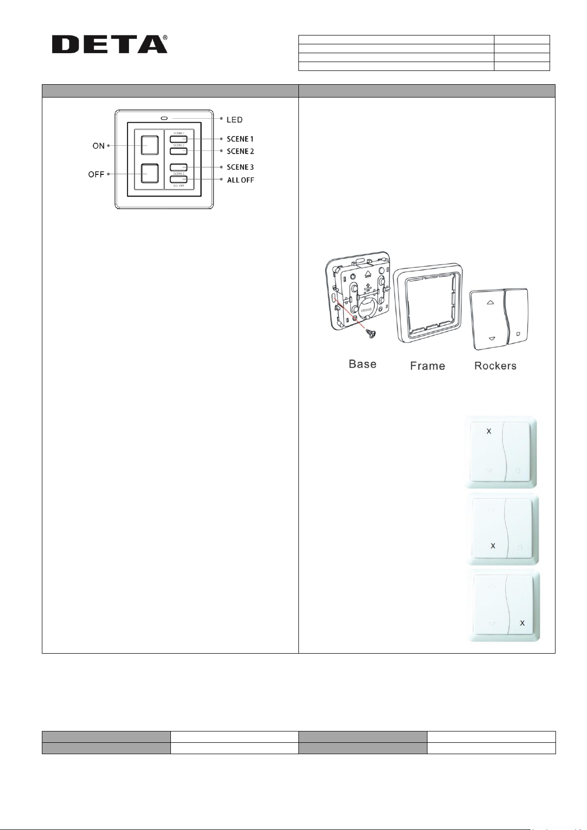
‘ON’ Button Press once to switch linked devices ‘ON’.
Press and hold the button to raise the dim level of any
linked dimmable receivers.
‘OFF’ Button: Press once to switch linked devices ‘OFF’.
Press and hold the button to dim the level of any linked
dimmable receivers.
‘ALL OFF’ Button: Press once to switch off all linked receivers at the same
time.
‘SCENE 1, 2, 3’ Buttons: Press any one of the scene buttons to recall that
particular stored scene (see ‘Setting up a Scene’).
The On/Off/Stop Switch is designed to operate the Connect Inline Relay,
catalogue number 9732.
The ‘Stop’ function makes it particularly useful for operating blinds, curtains
and automatic doors.
The following diagram illustrates how to dis-assemble the On/Off/Stop
Switch in order to screw the unit to a back-box, or to access the battery
compartment. Use a flathead screwdriver to gently remove the main keys
by inserting it into one of two small slots. The unit does not have to be
screw mounted and may instead be attached using the adhesive strips
provided.
The unit requires a CR2032 coin cell battery.
Tap the ‘on’ button to switch on the
linked Connect Inline Relay. This should
provide the ‘open’ function for blinds,
curtains, or doors.
Tap the ‘off’ button to switch off the
linked Connect Inline Relay. This should
provide the ‘close’ function for blinds,
curtains, or doors.
Tap the ‘off’ button to stop the linked
Connect Inline Relay, i.e. stopping the
blinds, curtains, or doors in mid
position.
Voltage
3V
Back Box Depth
Not required
Battery Type
CR2032 Lithium
Radio Frequency
433.92MHz
NPD0519 August 2016 MCINS2 V2 Tel: +44 (0)1582 544 544 Technical Helpline: +44(0)1582 544 548
DETA Electrical Company Limited
Kingsway House Laporte Way
Luton Bedfordshire LU4 8RJ UK
 Loading...