

Page 1
UltraFlex™ Drying & Firing Furnace
OWNER’S MANUAL
C-229
VERSION 3
12/2010
Page 2

PREFACE UltraFlex Drying and Firing Furnace Owner’s Manual
Revision
Date
Author
Description
1.0
11/2/2009
K. Livingston
Initial Release
1.1
5/24/2010
K. Livingston
Pre-Release Revisions
2.0
5/26/2010
K. Livingston
Revisions
3.0
12/6/2010
K. Livingston
Revisions
ii Version 3
Revision History
All rig hts reserved. No part of th e contents of th is m anual may b e r ep roduced, copied or t r ans mi t t ed i n any for m or b y any
means including graphic, electronic, or mechanical methods or photocopying, recording, or information storage and
retrieval systems without the written permission of Despatch Industries, unless for pu rchaser's personal use.
Copyright © 2010 by Despatch Industries.
Page 3

UltraFlex Drying and Firing Furnace Owner’s Manual PREFACE
Version 3 iii
Table of Contents
1. Abo ut This Manua l .............................................................................................. 9
1.1. Important User Information ........................................................................ 9
1.2. Manufacturer ............................................................................................ 10
1.3. Organization of this M anual ..................................................................... 10
1.4. Conventions Used in this Manual ............................................................. 10
1.5. Acronym Identifier ................................................................................... 11
2. Safety ................................................................................................................ 12
2.1. Safety I nforma tio n ................................................................................... 12
2.1.1. Lockout ................................................................................................ 12
2.1.1.1. Lockout Requirements ...................................................................... 12
2.1.1.2. Lockout Pro cedu r e ............................................................................ 12
2.1.2. Doors and Covers ................................................................................. 13
2.2. Maintenance ............................................................................................. 13
2.3. Electrical Power ....................................................................................... 13
2.4. Fire .......................................................................................................... 14
2.5. Equipment Lockout Requirements............................................................ 14
2.5.1. Emergency Sto p ................................................................................... 14
3. Theory of Operation........................................................................................... 16
3.1. UltraFlex Drying and Firing Furnace Machine States ............................... 17
3.1.1. Pow e r O ff ............................................................................................. 18
3.1.2. Initialization Mode ............................................................................... 18
3.1.3. Idle Mode ............................................................................................. 18
3.1.4. Loading Recipe Mode ........................................................................... 18
3.1.5. Stabilizat ion Mode ................................................................................ 19
3.1.6. Production Mode .................................................................................. 19
3.1.7. Cooldown Mode ................................................................................... 19
3.1.7.1. Quick Cooldown Mode ..................................................................... 19
3.1.8. Mainte nance Mod e ............................................................................... 20
3.2. Optimiz e d Recipes and Th erma l Profiling ................................................ 20
3.2.1. Thermal Profiling Pr ocess ..................................................................... 20
3.3. UltraFlex Dr yer ........................................................................................ 21
3.3.1. Overview .............................................................................................. 21
3.3.2. Transport System .................................................................................. 22
3.3.3. Heating System..................................................................................... 22
3.3.4. Process Ga s Syste m .............................................................................. 23
3.3.5. Oxidizer Airflow S ett ings ..................................................................... 24
3.4. Wafer Throughput .................................................................................... 24
3.5. VOC Ther mal Oxidize r ............................................................................ 25
3.6. Cha mber Lift Mecha n ism ......................................................................... 25
4. Software & Hardwar e S etu p .............................................................................. 27
4.1. Operation Overview ................................................................................. 27
4.2. Managing Use r s ....................................................................................... 29
All rig hts reserved. No part of th e contents of th is m anual may b e r ep roduced, copied or t r ans mi t t ed i n any for m or b y any
Copyright © 2010 by Despatch Industries.
means including graphic, electronic, or mechanical methods or photocopying, recording, or information storage and
retrieval systems without the written permission of Despatch Industries, unless for pu rchaser's personal use.
Page 4

PREFACE UltraFlex Drying and Firing Furnace Owner’s Manual
iv Version 3
4.2.1. Security Levels ..................................................................................... 29
4.2.2. Adding a User or Changing User Privileges .......................................... 30
4.3. Recipe Setup and Optimization ................................................................ 31
4.3.1. UltraFlex Furnace Set po int Ranges ....................................................... 31
4.3.2. Optimize Recipe Pro cess w ith Example ................................................ 33
4.4. Dryer/Firing Fur nace Airf low Setup ......................................................... 37
4.4.1. Dryer Airflow Setup ............................................................................. 37
5. Operation ........................................................................................................... 39
5.1. Routine Operat ion .................................................................................... 39
5.1.1. Overview .............................................................................................. 40
5.1.1.1. Using the Ultr aFle x Fur nace T ouch Screen Interface ......................... 40
5.1.1.2. Using On-Screen Controls ................................................................. 41
5.1.1.3. Process Overview .............................................................................. 41
5.1.1.4. Furnace Status ................................................................................... 42
5.1.1.5. Navigation Bar .................................................................................. 44
5.1.1.6. UltraFlex Drying and Firing Furnace Modes ..................................... 44
5.1.2. Navigating the Home Scree n ................................................................ 45
5.1.3. Trending Screen ................................................................................... 46
5.1.4. Recipe Screen ....................................................................................... 48
5.1.5. Alarm Screen ........................................................................................ 49
5.1.6. Setup Screen ......................................................................................... 51
5.1.7. Maintenance Screen .............................................................................. 51
5.2. Startup and Run the UltraFlex Drying and Firing Furnace ........................ 53
5.2.1. Starting from Idle Mo de ........................................................................ 54
5.2.2. Stopping from Production Mode ........................................................... 55
5.2.3. Entering Maintenance Mode from Idle Mode ........................................ 56
5.2.4. Entering Maintenance Mode from Production or Cooldown Mode ........ 56
5.3. Wor king with Trending ............................................................................ 56
5.3.1. Wor king with H ourly Perfo rmance ....................................................... 57
5.3.2. Conveyor .............................................................................................. 57
5.3.3. Heat ...................................................................................................... 58
5.3.4. Airflow ................................................................................................. 59
5.3.5. Cooling ................................................................................................. 60
5.3.6. Data ...................................................................................................... 61
5.3.7. E10 St at istics ........................................................................................ 63
5.3.7.1. E10 States ......................................................................................... 63
5.3.7.2. Operator Initiat ed St at es .................................................................... 64
5.4. Wor king with R ecip es .............................................................................. 64
5.4.1. Enter a New Recipe .............................................................................. 65
5.4.2. Wor king with Existing Recip e s ............................................................. 65
5.4.2.1. Load Existing Recipe ........................................................................ 65
5.4.2.2. I mport a Recipe ................................................................................. 66
5.4.2.3. Change a Recipe Value ..................................................................... 66
5.4.2.4. Export a Recipe ................................................................................. 67
All rig hts reserved. No part of th e contents of th is m anual may b e r ep roduced, copied or t r ans mi t t ed i n any for m or b y any
Copyright © 2010 by Despatch Industries.
means including graphic, electronic, or mechanical methods or photocopying, recording, or information storage and
retrieval systems without the written permission of Despatch Industries , unless for purchaser's personal use.
Page 5

UltraFlex Drying and Firing Furnace Owner’s Manual PREFACE
Version 3 v
5.4.2.5. Edit a Recipe on a PC ........................................................................ 68
5.4.2.6. Save a Recipe .................................................................................... 69
5.4.2.7. Delete a Recipe ................................................................................. 69
5.4.3. Recipes and the PLC ............................................................................. 69
5.4.4. Help with Recip es ................................................................................. 69
5.5. Working with Alar ms ............................................................................... 70
5.5.1. Acknowledge Alarms ........................................................................... 70
5.5.2. Info ....................................................................................................... 71
5.5.3. Events................................................................................................... 71
5.5.4. Alarm History ....................................................................................... 71
5.5.5. Audit History ........................................................................................ 72
5.6. Wor king with Set up ................................................................................. 72
5.6.1. User Administ ration ............................................................................. 73
5.6.1.1. Export and Import ............................................................................. 73
5.6.1.2. Help .................................................................................................. 74
5.6.2. Tool Calibra tio n ................................................................................... 74
5.6.2.1. Import and Export ............................................................................. 75
5.6.3. Creating an UltraFlex Fur nace Screen Shot ........................................... 75
5.7. Wor king with M aint ena nce Mode ............................................................ 76
5.7.1.1. Cha mber Lift ..................................................................................... 76
5.7.1.2. Display ............................................................................................. 77
5.7.1.3. Status ................................................................................................ 77
5.7.1.4. Exit ................................................................................................... 78
6. Preventive M aintenance ..................................................................................... 79
6.1. Control Systems Maintenanc e .................................................................. 81
6.1.1. Touch Screen Maintena nce a nd Calibration .......................................... 81
6.1.2. Panels ................................................................................................... 81
6.1.3. Chamber Seals ...................................................................................... 81
6.2. Conveyor Systems Maintenance ............................................................... 81
6.2.1. Bearings ............................................................................................... 81
6.2.2. Dr ive R olle r .......................................................................................... 81
6.2.3. Encoder ................................................................................................ 82
6.2.3.1. Inspect & Clean ................................................................................ 82
6.2.4. Conveyor .............................................................................................. 82
6.2.4.1. Inspect .............................................................................................. 82
6.2.4.2. Clean ................................................................................................ 83
6.2.5. Motors .................................................................................................. 83
6.2.6. Conveyor Guides .................................................................................. 83
6.2.7. Quartz Rods .......................................................................................... 83
6.2.7.1. Inspect .............................................................................................. 83
6.2.7.2. Clean ................................................................................................ 83
6.2.8. Conveyor Take-up ................................................................................ 84
6.2.9. Process Plumbing Assembly ................................................................. 84
6.3. Chamber Systems ..................................................................................... 85
All rig hts reserved. No part of th e contents of th is m anual may b e r ep roduced, copied or t r ans mi t t ed i n any for m or b y any
Copyright © 2010 by Despatch Industries.
means including graphic, electronic, or mechanical methods or photocopying, recording, or information storage and
retrieval systems without the written permission of Despatch Industries , unless for purchaser's personal use.
Page 6

PREFACE UltraFlex Drying and Firing Furnace Owner’s Manual
vi Version 3
6.3.1. Heater Lamps ....................................................................................... 85
6.3.1.1. Inspect .............................................................................................. 85
6.3.1.2. Replace ............................................................................................. 85
6.3.2. Thermocouples ..................................................................................... 86
6.3.3. Insulation .............................................................................................. 87
6.3.4. Dryer Casing ........................................................................................ 88
6.3.5. Protective Glass Layer .......................................................................... 88
6.4. Cooling/ V entilation Syst ems .................................................................... 88
6.4.1. Coils ..................................................................................................... 88
6.5. Exha ust Syst ems ...................................................................................... 88
6.5.1. Duct Hoses (3” & 4”) ........................................................................... 88
6.5.2. Exhaust Venturi Port............................................................................. 88
6.5.3. Exhaust Flow Restrictor Plate ............................................................... 89
6.5.4. Water Filter .......................................................................................... 91
6.5.5. VOC ..................................................................................................... 91
6.6. Lift Systems ............................................................................................. 91
6.6.1. Inspect .................................................................................................. 92
6.6.2. Clean & Maintain ................................................................................. 92
6.6.3. Chamber Lift Troubleshooting .............................................................. 93
6.6.3.1. Chamber Does Not Lift ..................................................................... 93
6.6.3.2. Chamber Lifts But Does Not Close or Does Not Close Completely ... 93
6.7. Insulation B urn-off ................................................................................... 94
6.7.1. Procedure for I nsulat ion Burnoff .......................................................... 95
6.7.2. Recommendations for Reducing Paste Cont aminatio n .......................... 96
7. Appendices ........................................................................................................ 97
7.1. Using UltraFlex Furn ace Data Files: Data & Diagnostic Logs .................. 97
7.2. UltraFlex Furnace Alarms ........................................................................ 97
7.3. Ultrasonic Belt Cleaner ............................................................................ 98
Copyright © 2010 by Despatch Industries.
All rig hts reserved. No part of th e contents of th is m anual may b e r ep roduced, copied or t r ans mi t t ed i n any for m or b y any
means including graphic, electronic, or mechanical methods or photocopying, recording, or information storage and
retrieval systems without the written permission of Despatch Industries , unless for purchaser's personal use.
Page 7

UltraFlex Drying and Firing Furnace Owner’s Manual PREFACE
Version 3 vii
Figures
Figure 1. UltraFlex Fur nace E mergenc y Stop Locations. ............................................... 15
Figure 2. UltraFlex Infrared Firing and Drying Furnace in Manufacturing Line. ............ 16
Figure 3. UltraFlex Fur nace Machine States. ................................................................. 17
Figure 4. The UltraFlex Dr yer Transpo r ts Wafers through Multiple Chambers. ............. 22
Figure 5. Set Four Dryer Pro cess Air MFCs Using the Recipe Screen. ........................... 23
Figure 6. Despat ch VOC Ther mal Oxidizer Oper at io n. .................................................. 25
Figure 7. Typical Home Screen (UltraFlex). .................................................................. 27
Figure 8. UltraFlex Drying and Firing Furnace Software Navigation. ............................ 28
Figure 9. Press Setu p and then Users to Add o r Change User Information. .................... 30
Figure 10. Enter or Change User In formation with the Setup/User Administ r ation Screen.
...................................................................................................................................... 30
Figure 11. Typical Firing Zone Setpoints vs. Actual Temperatures. ............................... 32
Figure 12. Adjusting Value on Detail Bo x. .................................................................... 36
Figure 13. UltraFlex Fur nace Home Screen. .................................................................. 39
Figure 14. Use On-Screen Keypad or Keyboard to Enter D ata. ...................................... 40
Figure 15. Using On-Screen Co ntrols. ........................................................................... 41
Figure 16. UltraFlex Fur nace Home Screen—Process Overv iew. .................................. 42
Figure 17. UltraFlex Fur nace Home Screen—Furnace Status. ....................................... 43
Figure 18. Typical Deta il Scree n for Furnace Temperature Zone 1. ............................... 43
Figure 19. UltraFlex Fur nace Home Screen—Navigation Bar. ....................................... 44
Figure 20. Trending Screen. .......................................................................................... 46
Figure 21. Histor y Trending/Furnace Zone 1 Screen. ..................................................... 47
Figure 22. Recipes Scree n and Pop-up Screen for Parameters Descr ipt ions. .................. 48
Figure 23. Alarms Screen and Close-up of Unacknowledged Alarms............................. 49
Figure 24. Alarm Histor y Scree n. .................................................................................. 50
Figure 25. System Event Alar m Screen. ........................................................................ 50
Figure 26. Setup Screen. ................................................................................................ 51
Figure 27. Maintenance Screen with Close-up. .............................................................. 52
Figure 28. Confirm LEL Settings Dialogue Window. .................................................... 53
Figure 29. Start Production Mode from Idle Mode. ........................................................ 54
Figure 30. LEL Dialogue Window. ................................................................................ 54
Figure 31. Stabilization Mode. ....................................................................................... 54
Figure 32. Tool in Production Mode. ............................................................................. 55
Figure 33. Trending Main Screen. ................................................................................. 56
Figure 34. Conveyor Trending Screen. .......................................................................... 57
Figure 35. Heat Trending Screen. .................................................................................. 58
Figure 36. Airflow Trending Screen. ............................................................................. 59
Figure 37. Cooling Trending Screen. ............................................................................. 60
Figure 38. Data Logging Screen. ................................................................................... 62
Figure 39. Front and Rear USB Ports. ............................................................................ 62
Figure 40. E10 Statistics Screen. ................................................................................... 63
Figure 41. Operato r Selects Equipment State. ................................................................ 64
Figure 42. Work with Exist ing or N ew Recipes Using the Recipe Screen. ..................... 65
All rig hts reserved. No part of th e contents of th is m anual may b e r ep roduced, copied or t r ans mi t t ed i n any for m or b y any
Copyright © 2010 by Despatch Industries.
means including graphic, electronic, or mechanical methods or photocopying, recording, or information storage and
retrieval systems without the written permission of Despatch Industries , unless for purchaser's personal use.
Page 8

PREFACE UltraFlex Drying and Firing Furnace Owner’s Manual
viii Version 3
Figure 43. Recipe with Comment Dialogue Box Open. .................................................. 67
Figure 44. Recipe File Saved as CSV File. .................................................................... 68
Figure 45. Alarms Screen. ............................................................................................. 70
Figure 46. Alarms Events Screen. .................................................................................. 71
Figure 47. Alarm Histor y Scree n. .................................................................................. 71
Figure 48. Audit History Screen. ................................................................................... 72
Figure 49. User Administr ation Screen. ......................................................................... 73
Figure 50. User Administr ation Help Screen. ................................................................. 74
Figure 51. Tool Calibration Screen. ............................................................................... 74
Figure 52. Press the Despat ch Log o to Cr eate a Screen Shot on the USB stick. .............. 75
Figure 53. Conveyor Chamber Lift Verify Screen. ......................................................... 76
Figure 54. Display Screen.............................................................................................. 77
Figure 55. Status Screen for Troubleshooting. ............................................................... 78
Figure 56. Listen for So unds o f Bearing Failur e every Three Months. ........................... 81
Figure 57. Inspect and C lean Encoder Weekl y. .............................................................. 82
Figure 58. Inspect Conveyor Take-up for Ease of Movement......................................... 84
Figure 59. Inspect Plumbing for Leaks every Six Months. ............................................. 84
Figure 60. Lamp Box Covers Removed. ........................................................................ 85
Figure 61. Attach Wago block. ...................................................................................... 86
Figure 62. Replace Thermoco u ple. ................................................................................ 86
Figure 63. Replace Insu lat ion "T" Piece. ....................................................................... 87
Figure 64. Restr ictor Plate. ............................................................................................ 89
Figure 65. Remove exhaust ho using to access restrictor plate. ....................................... 90
Figure 66. Inspect Wat er Filter Mo nt hly and Repla ce Filter as Necess ary. ..................... 91
Figure 67. Contaminated Dryer Zone Before (left) and After (right) Insulation Burn-off
procedure. ..................................................................................................................... 94
Tables
Table 1. UltraFlex Security Levels. ............................................................................... 29
Table 2. UltraFlex Furnace T ypical Setpoint Ranges. .................................................... 31
Table 3. Guideline to Determine Number of Firing Zones. ............................................ 34
Table 4. Determine LEL Alert and Alar m Levels. .......................................................... 38
Table 5. UltraFlex Firing & Drying Furnace Modes. ..................................................... 44
Table 6. Burnoff Recipe Settings. .................................................................................. 95
Copyright © 2010 by Despatch Industries.
All rig hts reserved. No part of th e contents of th is m anual may b e r ep roduced, copied or t r ans mi t t ed i n any for m or b y any
means including graphic, electronic, or mechanical methods or photocopying, recording, or information storage and
retrieval systems without the written permission of Despatch Industries , unless for purchaser's personal use.
Page 9

UltraFlex Drying and Firing Furnace Owner’s Manual ABOUT THIS MANUAL
Version 3 9
1. About This Manual
1.1. Important User Information
Copyright © 2010 by Despatch Industries.
All rights reserved. No p art of the cont ent s of this manual may be reproduced, copied, or
transmitted in any form or by any means including graphic, electronic, or mechanical
methods or photocopying, recording, or info rmation storage and re trieval syst ems w ithou t
the written permission of the publisher, unless it is for t he purchaser 's perso na l use.
Printed and bound in the United St at es of Amer ica.
The i nformation in this manu al is s ubje ct to change without notice and d oes not represent
a commitment on the part of Despatch Industries. Despatch Industries does not assume
any responsibility for any errors that may appear in this manual.
In no event will Despatch Industries be liable for technic al or editorial omissions made
herein, nor for direct, indirect, spe cial, inc identa l, or consequential damages resulting
from the use or defect of this manual.
Values displayed on screens are examples only. Though
O
O
The i nformation in this doc ument is not intended t o co ver all poss i ble c ond itions and
situations that might occur. The end user must exerc ise caut ion and common sens e when
installing or maintaining Despatch Industries products. If any questions or problems
arise, call Despatch Industries at 1-888-DESPATCH or 1-952-469-5424.
All rig hts reserved. No part of th e contents of th is m anual may b e r ep roduced, copied or t r ans mi t t ed i n any for m or b y any
means including graphic, electronic, or mechanical methods or photocopying, recording, or information storage and
retrieval systems without the written permission of Despatch Industries , unless for purchaser's personal use.
those values may be typical , cont act Despatch Industries for
the final value.
Actual screens may vary from those published in this manual.
Copyright © 2010 by Despatch Industries.
Page 10
ABOUT THIS MANUAL UltraFlex Drying and Firing Furnace Owner’s Manual
This icon signifies information that describes an unsafe
Danger!
A condition that may result in death, serious injury or
damage to equipment.
Warning!
A condition that may result in serious injury or damage to
equipment.
Caution!
A condition that may res ult in da m a ge t o equipme nt or
product.
LOG OUT
Bold, 10pt Arial typeface indicates a specific key or butto n
on screen to click.
10 Version 3
1.2. Manufacturer
The UltraFlex Drying and Firing Furnace is manufact ur ed by:
Despatch Industries
8860 207th Street
Lakeville, MN 55044
1-952-469-5424 • 1-888-DESPATCH
www.despatch.com
Refer to the UltraFlex Drying and Firing Furnace name plate for a lis t o f machine
specifications a nd t echnical support contact infor mat ion.
1.3. Organization of this Manual
The Owner’s manual c ont ains the most comprehensive set of information for the
UltraFlex™ Firing and Drying Furnace.
1.4. Conventions Used in this Manual
O
This icon sig ni f ies imp o rtant information.
condition that may result in death, serious injury, or damage
to the equipment.
All rig hts reserved. No part of th e contents of th is m anual may b e r ep roduced, copied or t r ans mi t t ed i n any for m or b y any
means including graphic, electronic, or mechanical methods or photocopying, recording, or information storage and
retrieval systems without the written permission of Despatch Industries , unless for purchaser's personal use.
Copyright © 2010 by Despatch Industries.
Page 11

UltraFlex Drying and Firing Furnace Owner’s Manual ABOUT THIS MANUAL
Acronym:
Refers to:
CDA
Clean, Dry Air
GUI
Graphical User Interface
HMI
Human-Machine Interface
IR
Infrared
Lpm
Liters per minute
MFC
Mass Flow Controller
PLC
Programmable Logic Controller
SSR
Solid State Rel ay
SCR
Silicon-Controlled Rectifier or Semiconductor-Controlled Rect ifier
VFD
Variable Frequenc y Drive
VOC
Volatile Organi c Com pound
Version 3 11
1.5. Acronym Identifier
All rig hts reserved. No part of th e contents of th is m anual may b e r ep roduced, copied or t r ans mi t t ed i n any for m or b y any
means including graphic, electronic, or mechanical methods or photocopying, recording, or information storage and
retrieval systems without the written permission of Despatch Industries , unless for purchaser's personal use.
Copyright © 2010 by Despatch Industries.
Page 12

SAFETY UltraFlex Drying and Firing Furnace Owner’s Manual
Danger!
12 Version 3
2. Safety
2.1. Safety Information
Do not wo rk on the UltraFlex D ryin g and Fir ing Furnac e without read ing and
understanding this section which contains important information and warnings. Ignoring
these warnings can result in death, serious injury or damage to the machine and product.
2.1.1. Lockout
Machine lockout places t he UltraFlex Drying and Firing Furnace into a zero energy state
and prevents accidental machine start up. Always fo llow the Lock out Procedure
described in this Section before cleaning, maintaining or repairing the U ltraFlex Drying
and Firing Furnace. An accidental start-up, wh ile wo rking on the Ult raFlex Drying and
Firing Furnace, can result in serious injury or death.
2.1.1.1. Lockout Requirements
1. Every power source that can energ ize an y element of the UltraFlex Drying and Firing
Furnace must be shut off at the closest po ss ible power source. This includes air, wa ter
and electricity.
2. After energy sources are locked out, test to ensure circuits are de-energized.
2.1.1.2. Lockout Procedure
Personnel author ized to lockout equipment must have the necessar y locks to perform the
lockout.
1. Physically disconnect all electrical power to the machine or lockout the appro pr iate
breaker or disconnects.
2. Close all valves for air or water sour ces and bleed off any pressure.
3. Test for power by attempt ing a start with the machine cont rols.
Electric a l pa ne ls conta in high voltage. Disconnec t a nd loc k o ut
the power supply before working inside any electrical panels.
Failure to lock out the power supply can result in death or injury.
4. Identify the Locko ut Co nd ition with a t ag o n the electr ical disco nnect and p neu matic
shut off valve .
5. When work is complete, r emove all tags and rest ore the machine to its working state.
All rig hts reserved. No part of th e contents of th is m anual may b e r ep roduced, copied or t r ans mi t t ed i n any for m or b y any
means including graphic, electronic, or mechanical methods or photocopying, recording, or information storage and
retrieval systems without the written permission of Despatch Industries , unless for purchaser's personal use.
Copyright © 2010 by Despatch Industries.
Page 13
UltraFlex Drying and Firing Furnace Owner’s Manual SAFETY
Danger!
Danger!
Failure to lock out the power supply can result in death or injury.
Version 3 13
2.1.2. Doors and Covers
Doo rs and c overs on the UltraFlex D ryin g and Fir ing Furnace pr otect against the hazards
beh ind t hem. O pera tion withou t thes e sa fety devices in place creates hazards that the
doors and covers are intended to render safe for pers onne l . Inspect the U ltra Flex Drying
and Firing Furnace periodically to make sure the doo r s and covers are in place.
Electrical panels contain high v olt age. Disconnec t a nd loc k out
the power supply before working inside any electrical panels.
All doors on this machine have fast eners that latch to the frame and require a tool to
open. Panels and doo r s that req uire a too l to open are part of the safety system of the
UltraFlex Drying and Firing Furnace. Do not open any doors while the machine is
running.
2.2. Maintenance
Only qualified and trained personnel should perform maintenance or repair.
2.3. Electrical Power
Only qualified and trained personnel should perform electrical maintenance or electrical
repair.
• Before perfo rm ing maintenance, disco nnect all electrical power fro m the machine.
Use a padlock and lockout all disco nnect s feeding power to the machine.
• Never clean, lubricate or repair the furnace whe n in operation.
Contact with energized electrical sources may result in serio us
injury or death.
Copyright © 2010 by Despatch Industries.
All rig hts reserved. No part of th e contents of th is m anual may b e r ep roduced, copied or t r ans mi t t ed i n any for m or b y any
means including graphic, electronic, or mechanical methods or photocopying, recording, or information storage and
retrieval systems without the written permission of Despatch Industries , unless for purchaser's personal use.
Page 14
SAFETY UltraFlex Drying and Firing Furnace Owner’s Manual
Danger!
Danger!
14 Version 3
• Unauthorized alterations o r modifications to UltraFlex Drying and Firing Furnace are
strictly forbidde n. Never modify any electrical circuits. Unaut ho r ized mod ifications
can impair the funct ion and saf e ty of the UltraFlex Drying and Firing Furnace.
Systems equipped with an uninterruptible power supply (UPS)
may require that the UPS be powered OFF manually to
disconnect all elect rical power.
2.4. Fire
Keep the UltraFlex Drying and Firing Furnace clean and free o f scrap mat er ials, oil or
solvents to pre vent the poss i bility of f ire. In the eve nt o f fire, use a fire extinguisher as
follows.
1. De-energize the machine immediately by pushing an Emergency Stop push button
2. Turn off the remote main disconnect (customer supplied disco nnect ) .
3. Extinguish the f ire.
2.5. Equipment Lockout Requirements
2.5.1. Emergency Stop
Always disconne c t a ll power before extinguishing a fire.
Attempting to extinguish a fire in a machine connected to
electrical power can result in serious injury or death!
To prevent injury or equipment damage during inspection or repair, the UltraFlex Drying
and Firing Furnace must be locked out.
When a risk of personal injury or d amage to the Ult r aFlex Drying and Firing Furnace
exists, push an Emergency Stop operator. This shuts off all electrical power to the
machine. Figure 1 shows lo ca tion of Emergency Stop operators.
All rig hts reserved. No part of th e contents of th is m anual may b e r ep roduced, copied or t r ans mi t t ed i n any for m or b y any
means including graphic, electronic, or mechanical methods or photocopying, recording, or information storage and
retrieval systems without the written permission of Despatch Industries , unless for purchaser's personal use.
Copyright © 2010 by Despatch Industries.
Page 15

UltraFlex Drying and Firing Furnace Owner’s Manual SAFETY
Unload
View
Load End
Product
Flow
Emergency Stop Loc ations
UltraFlex
Figure 1. UltraFlex Furnace Emergency Stop Locations.
Version 3 15
Furnace
Emergency
Stop
View
Copyright © 2010 by Despatch Industries.
All rig hts reserved. No part of th e contents of th is m anual may b e r ep roduced, copied or t r ans mi t t ed i n any for m or b y any
means including graphic, electronic, or mechanical methods or photocopying, recording, or information storage and
retrieval systems without the written permission of Despatch Industries , unless for purchaser's personal use.
Page 16
THEORY OF OPERATION UltraFlex Drying and Firing Furnace Owner’s Manual
Furnace
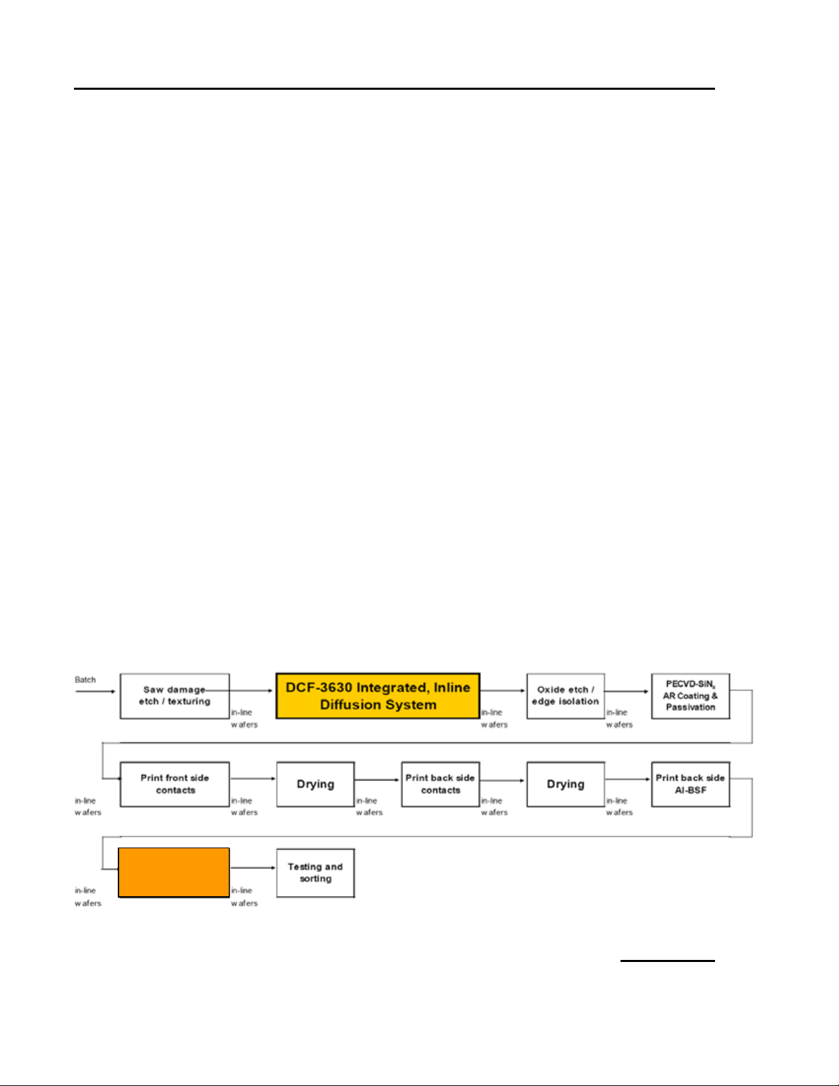
Figure 2. Ultra Flex Infrared Firi ng and Dryi ng Furnace in Manufact uri ng Line.
16 Version 3
3. Theory of Operation
The Despatch UltraFlex fur nace is a second generation in-line (co nveyor ized) furnace
(following the Despatch C F/CDF series). It is designed for use in photovoltaic
manufacturing lines for the express purpose of drying and firing metalized paste to
silicon substr ates. The furnace process immediate ly follows the last scr een printing step
(typical manufacturing process ste ps sho wn in Figure 2).
The UltraFlex furnace is avai la ble as a firing fur nace alone (Model FF) or wit h a n
inte gral dryer (Model DFF). The func tion of the dryer portion of the machine is to
liberate Volatile Orga nic Compounds (VOCs) from the scree n printed substrate to
prevent firing ano malies. I nfrared r adiation and resistant heaters pro vide the heat source
for the drying process. T he U ltraF lex dr yer inco r porates a self-co ntained oxidation
system that incinerates VOCs at the point of evacuat ion or exhaust. VOCs are exhausted
near the entrance and exit o f the dryer d irect ly into individua l Thermal Oxidizers. Each
Ther ma l Ox id iz er is ind ep e nd e ntly mo nit o r e d and cont rolled to ensure t emperature and
flow are maintained within proper limits to achieve VOC destruction.
The function of the furnace is to sinter t he screen-printed and dried paste to the
silicon substr ate as the final manu fact u r ing step in producing a solar cell. T he furnace
uses infrared r adiation as a heat source and a combination rad iant/convective chiller to
remove heat from the product and belt prior to exiting the machine.
From beginning to end the drying/firing process entails drying, binder (polymer)
burn-out, sinte ring and co ol-down. Production speeds are approximately 457.2- 698.5
cm per minute (180-275 inches per min ute ).
Both the dryer and furnace use an in d u s trial pro gr am mab le logic controller (PLC)
and Microsoft Windows t ouc h s c reen PC (human-machine interface, or HMI) as the
primary control platform and human/machine inter face respectively. All so ftwar e is
proprietar y to Despatch Industries.
UltraFlex Drying
and Firing
All rig hts reserved. No part of th e contents of th is m anual may b e r ep roduced, copied or t r ans mi t t ed i n any for m or b y any
means including graphic, electronic, or mechanical methods or photocopying, recording, or information storage and
retrieval systems without the written permission of Despatch Industries , unless for purchaser's personal use.
Copyright © 2010 by Despatch Industries.
Page 17
UltraFlex Drying and Firing Furnace Owner’s Manual THEORY OF OPERATION
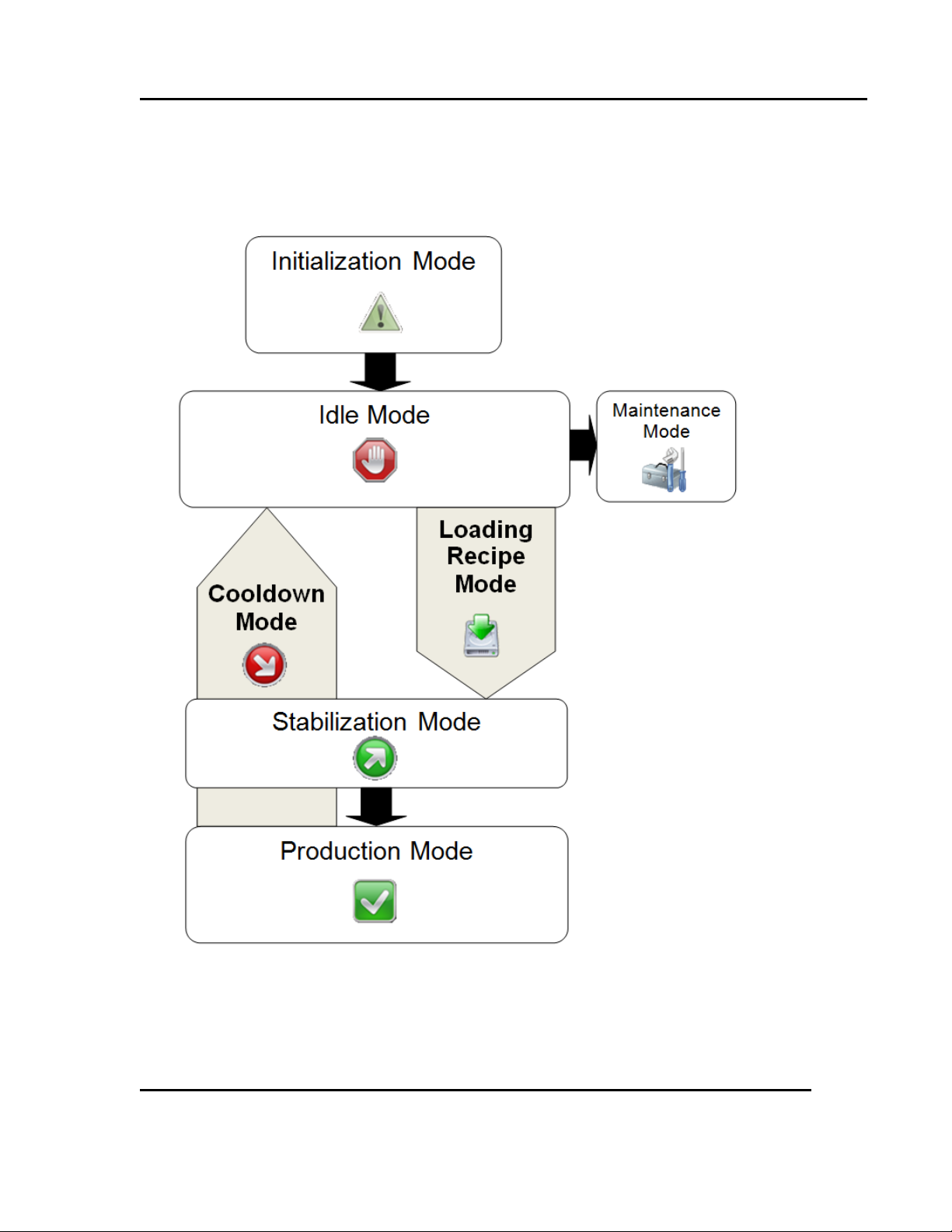
Figure 3. UltraFlex Furnace Machine States.
Version 3 17
3.1. UltraFlex Drying and Firing Furnace Machine States
The UltraFlex Drying and Firing Furnace operates using a series of seven modes. The
tool dries and diffuses wafers using the Production Mode (Figure 3).
All rig hts reserved. No part of th e contents of th is m anual may b e r ep roduced, copied or t r ans mi t t ed i n any for m or b y any
means including graphic, electronic, or mechanical methods or photocopying, recording, or information storage and
retrieval systems without the written permission of Despatch Industries , unless for purchaser's personal use.
Copyright © 2010 by Despatch Industries.
Page 18
THEORY OF OPERATION UltraFlex Drying and Firing Furnace Owner’s Manual
18 Version 3
3.1.1. Power Off
Tool is OFF. Power the tool ON at the main breaker.
3.1.2. Initialization Mode
Initial entry state when st arting the pro gram. During Initialization, t he system performs
startup sequences such as:
• Diagnostic routines check for hardware er rors
• System checks for local/remote I /O st atu s. If necessar y, erro r messages display and
program remains in Initialization Mode.
• The Human Machine Interface (HMI) and t he Pro gra mmable Logic Controller (PLC)
are both powered u p into the “Run” state. Recipe values are matched and the last
running recipe is loaded. Note that a default recipe is de fined at t he first start up
• After successful diagnostic rout ines and checks, the system sets displays and o utputs
to defa ult co nd itions and ente rs t he Idle Mode
3.1.3. Idle Mode
The Idle Mode allows for recipe creation, editing and selection, withou t need to run the
entire system. Idle Mode includes these conditions:
• The t o ol is idl e .
• If alarm conditions exist (for instance wait ing because of E-stop, high temperat ur e
limit or power low), those conditions must be acknowledged before starting the tool.
In fa c t, exception condit io ns may cause t he syst em to switch to the Stabilization or
Cooldown states. A separat e HMI “E-STOP Reset” sets a relay output that re sets the
safety circuit.
• All alarms are enabled
3.1.4. Loading Recipe Mode
The Loading Recipe Mode simply begins the load ing process for the selected recipe.
After loading a recipe, t he user can star t Production Mode.
All rig hts reserved. No part of th e contents of th is m anual may b e r ep roduced, copied or t r ans mi t t ed i n any for m or b y any
Copyright © 2010 by Despatch Industries.
means including graphic, electronic, or mechanical methods or photocopying, recording, or information storage and
retrieval systems without the written permission of Despatch Industries , unless for purchaser's personal use.
Page 19
UltraFlex Drying and Firing Furnace Owner’s Manual THEORY OF OPERATION
Version 3 19
3.1.5. Stabilization Mode
In Stabilizat ion Mode the system monitor s the process values until they a re within a
defined window and then proceeds to the Product io n Read y stat e when the system is
stable.
3.1.6. Production Mode
Production Mode is the machine state used for production and maintains process values
status with respect to r ecipe-specified target set points and deviation limits.
• Deviatio n exceptions and physical input exception conditions may cause the system
to automatically switch t o t he St ab ilization or Cooldown states.
• If the user selects to stop the process using the HMI console, the system enters the
Cooldown state.
3.1.7. Cooldown Mode
In the Cooldown state, dr yer and furnace heating is disabled while other systems
(including coo ling water, airflow, and oxidizer) hold the t hresho ld temperature.
• When heat zones have cooled below the Cooldown thres hold, the system shuts
everything off and enters t he Idle Mode.
• Using the Rapid Cool option, the system opens the chamber to approximately one
inch for rapid cooling.
3.1.7.1. Quick Cooldown Mode
In quick Cooldown mode, the chamber opens slightly for more rapid cooling. Quick
Cooldown mode follows this process:
• Audible alarm sounds
• Casing lowers roughly 80 mm
• The conve yor is O N
• The tool goes to Idle Mode
Copyright © 2010 by Despatch Industries.
All rig hts reserved. No part of th e contents of th is m anual may b e r ep roduced, copied or t r ans mi t t ed i n any for m or b y any
means including graphic, electronic, or mechanical methods or photocopying, recording, or information storage and
retrieval systems without the written permission of Despatch Industries , unless for purchaser's personal use.
Page 20
THEORY OF OPERATION UltraFlex Drying and Firing Furnace Owner’s Manual
Warning!
20 Version 3
3.1.8. Maintenance Mode
Manually select Maintenance Mode to serv ice the too l:
• Maintenance state is open loop control mode only. 0-100% power control is
available.
• User inputs are blocked to ensure safe oper ation of the tool.
• General alarms (for instance, temperatu re hi gh and low) are
not active in Maintenance Mode.
• Safety interlocks remain active in Maintenance Mode.
Only qualified and trained personnel should perform
O
O
maintenance or repai r
Access to Maintenance Mode is available only when the
chamber temperature is below the Cooldown threshold.
.
3.2. Optimized Recipes and Thermal Profiling
The UltraFlex furnace optimizes hea t transfer for firing so s etpoints may be lower
compared to other furnaces. During UltraFlex furnace fast firing and cooling profiles
(those greater than 125°C/second), a wafer measured with a light gauge thermocouple
spring typicall y under-reports true wafer temperature. Contact Despatch Global
Headquarters for:
• A method to optimize the efficiency of a wafer through design o f experiments
• The Despatch measure me nt to ol that more reliably reports wafer temperature
3.2.1. Thermal Profiling Process
Thermal profiling co nsist s o f these general steps:
1. Determine the pro file windo w. What needs to be accomplished with each wafer as it
mo v es f r om drying to burnout to firing to cooling?
Copyright © 2010 by Despatch Industries.
All rig hts reserved. No part of th e contents of th is m anual may b e r ep roduced, copied or t r ans mi t t ed i n any for m or b y any
means including graphic, electronic, or mechanical methods or photocopying, recording, or information storage and
retrieval systems without the written permission of Despatch Industries , unless for purchaser's personal use.
Page 21

UltraFlex Drying and Firing Furnace Owner’s Manual THEORY OF OPERATION
Version 3 21
2. Determine process speeds: Conveyor maximum and minimum speeds based on the
entire line as well as the paste manufactu r er ’s process window.
3. Determine the number o f firing zones req uired for the profile.
4. Determine airflow rates (dryer and furnace), cooling r at es and burno ut t emperature.
Due to the use of Microzone™ technology, conventiona l high
temperatures and fast bel t speeds are not required.
O
While eight zones using Microzone technology are available,
typical profiles make use of three to four zones.
Additio n al s teps may include:
• Adjusting Micro zone™ technology to optimize the profile
• Adjusting the final wafer t emperat ur es
• Testing the process using thermoco u ple assemb lies and samp les
• Reviewing cell electrical results, adjusting settings and rerunning the process
Refer to Recipe Setup and Optimization (4.3) for specific setup instructions.
3.3. UltraFlex Dryer
3.3.1. Overview
To achieve the desired rheo log ica l and other compositional qualities, all photovoltaic
(PV) metallization pastes contain volatile organ ic co mpounds ( VOC) . After printing with
these pastes, the printed ce lls must be properly dried to avoid the release of hazardous
fumes into the furnace, to avo id excessive equipment contamination and to achieve
VOCs max imum cell pe rformanc e .
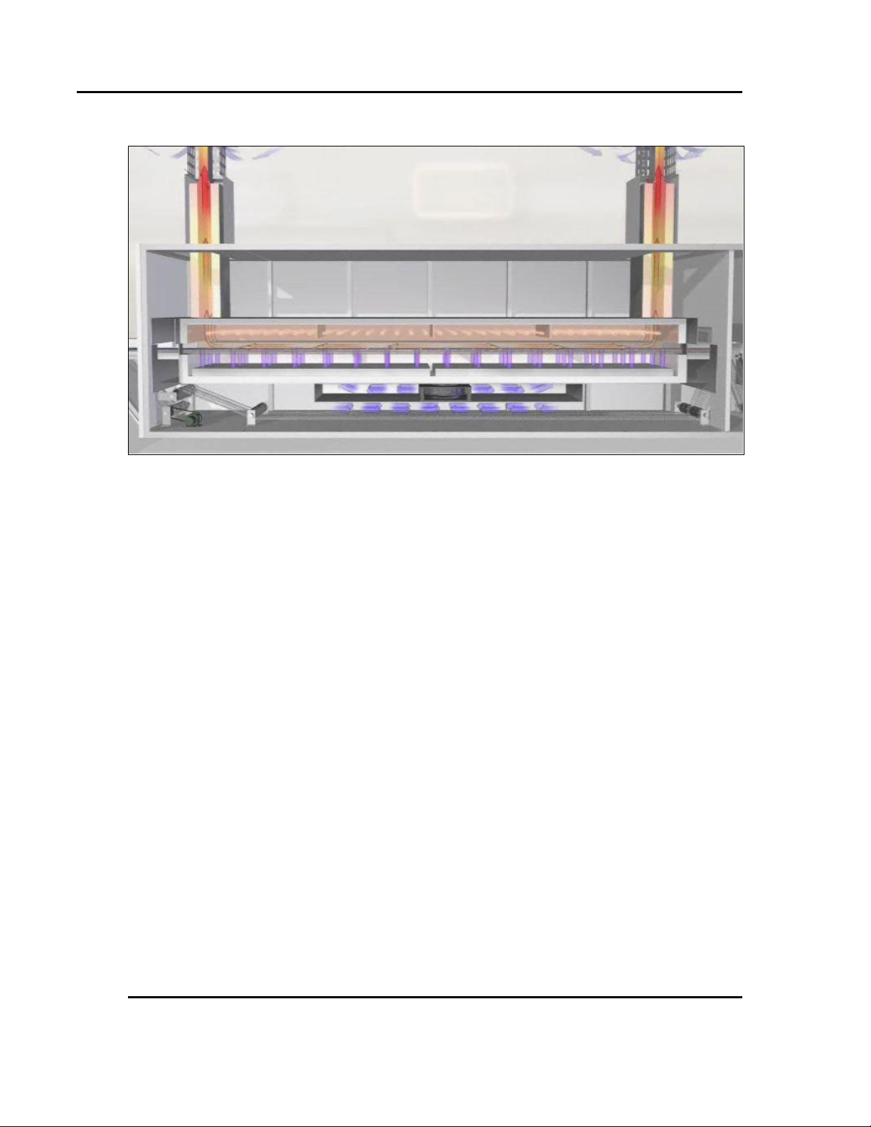
The UltraFlex Dryer tr anspo rts printed cells (wafers) through multiple integrated,
independently-controlled heating chambers using a variable-speed conveyor (Figure 4).
The wafers are heated to a temperat u r e that liberat es volatiles from the paste and
evacuates the VOCs fro m the heat ing chamber us i ng a c losed-loop control process gas
system. The VO Cs are then exhausted into the integr ated thermal oxidizer where they are
destroyed leaving only CO and HO byproducts. The wafer is then transferred d irectly
into the firing furnace for furt her pr ocessing.
All rig hts reserved. No part of th e contents of th is m anual may b e r ep roduced, copied or t r ans mi t t ed i n any for m or b y any
means including graphic, electronic, or mechanical methods or photocopying, recording, or information storage and
retrieval systems without the written permission of Despatch Industries , unless for purchaser's personal use.
Copyright © 2010 by Despatch Industries.
Page 22
THEORY OF OPERATION UltraFlex Drying and Firing Furnace Owner’s Manual
Figure 4. The UltraFlex Dryer Transports Wafer s t hrough Multi ple Chambers.
22 Version 3
3.3.2. Transport System
The wafer transport syste m co ns ists of a me sh b e lt, drive motor, progra mma ble logic
controller (PLC), variable fre que ncy drive s (VFDs), encoders, wafer senso r s, prec ision
gu ides and an internal s upport syst em. The mesh be lt is desig ned to contact the wafers
o n l y a t the outer extre m ities, minimizing surface damage and allowing uniform heating
w ith out inf lue nce from belt contact. Belt speed is cont rolled with a clo sed loop syste m
including the PLC, VFD, motor and encoder. The transport system is designed t o operate
from 64-635 cm/min with an accuracy of ± 0.5%. The conveyor is supported within the
chamber by a series o f quartz rods secured by glass plates within the refractory. Wafer
sensor photo-eyes are secured on the entrance and exit of the chamber t o ensure sa fe
operation of the machine below the lower explosive limit of the pro cessed VOCs.
3.3.3. Heating System
The heating s ys tem includes three separat e yet integ r ated systems. The lower portion of
the chamber has resistance-coil heating for preheating t he process gas introduced in the
chamber. The dryer upper chamber contains infrar ed ( IR) lamps to heat t he wafers to the
point of solvent evacuation as they pass through the chamber. T he o xidizer resistance coil
heaters destro y the VOCs remo ved from the wafer in the process. All three heat ing
syste ms are close-loop controlled via PLC, thermocouples, SSR and SCRs. T he typical
operation temperatu r e of the lower cha mber pr ehe ater is approximately 350 °C. IR lamp
All rig hts reserved. No part of th e contents of th is m anual may b e r ep roduced, copied or t r ans mi t t ed i n any for m or b y any
Copyright © 2010 by Despatch Industries.
means including graphic, electronic, or mechanical methods or photocopying, recording, or information storage and
retrieval systems without the written permission of Despatch Industries , unless for purchaser's personal use.
Page 23
UltraFlex Drying and Firing Furnace Owner’s Manual THEORY OF OPERATION
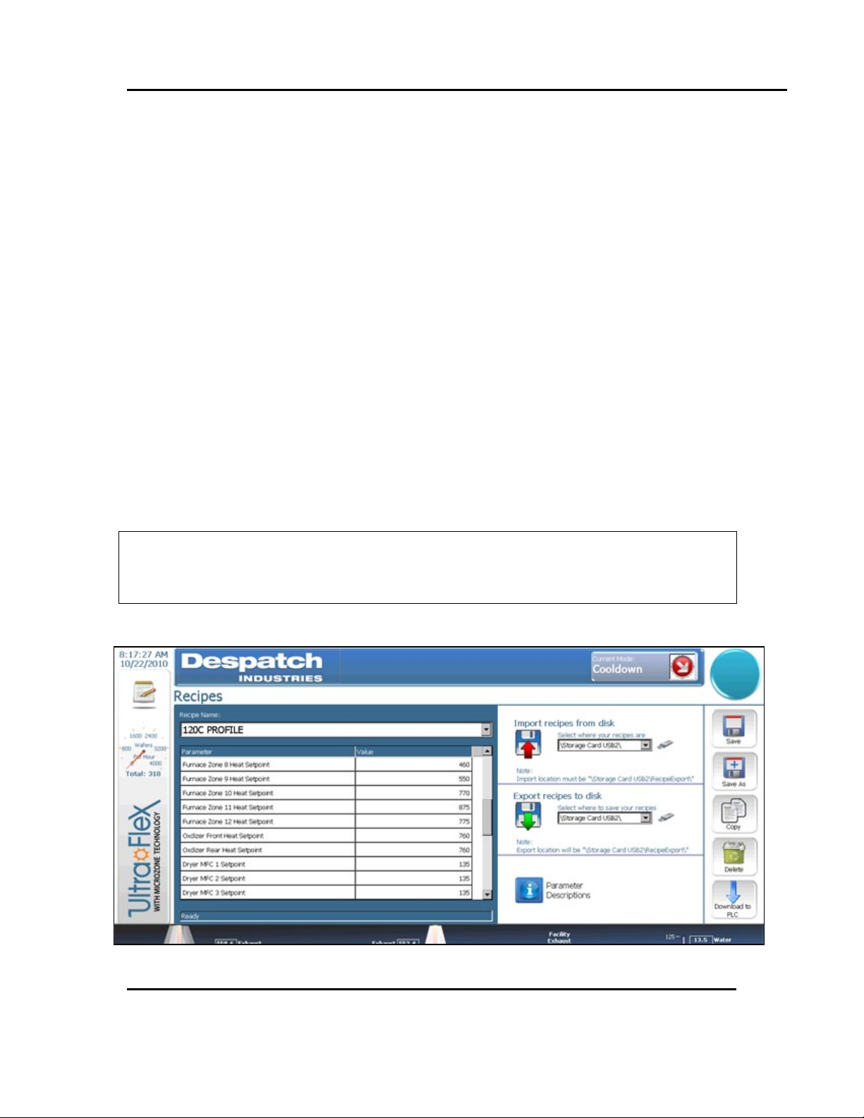
Figure 5. Set Four Dryer Process Air MFCs Using the Rec ipe Scree n.
Version 3 23
heaters operat e in a typical range of 200-550 °C and the oxidizer operates at 760 °C.
Set points and toleranc es for a ll heating systems are a function of setting the recipe.
3.3.4. Process Gas System
Process gas is delivered using a cont rol system made up of the PLC, mass f low
controllers (MFC), proportioning valves and monito r ing pressure transducers. Air i s
introduced into the upper and lower dryer heating chambers by the M FCs, whe re it is
preheated and delivered t o t he chamber ca vity. MFCs provide exhaust air flow to each
dryer zone to clear the VOCs. O xidizer s evacuate contaminated p ro cess a ir at t he ends of
the chambers and destro y the VOCs, leaving only CO2 and H2O byproducts.
Note:
• Two proportioning valves are facto r y set to achieve and maintain the required flow
for oxidizer air. Tw o additional facto ry-set proportioning valves provide dryer
entrance and exit air sparges (air curtains).
• Set any of the four dryer process air MFCs by using the Recipe screen (Set Four
Dryer Pr ocess Air MFCs U sing the Recipe Screen.).
• The PLC uses pressure transducers (there are several) to convert pressure to flow
numbers for control, display and alarm purposes.
Only Despatch personnel are permitted to change proportionin g
O
valves.
All rig hts reserved. No part of th e contents of th is m anual may b e r ep roduced, copied or t r ans mi t t ed i n any for m or b y any
means including graphic, electronic, or mechanical methods or photocopying, recording, or information storage and
retrieval systems without the written permission of Despatch Industries , unless for purchaser's personal use.
Copyright © 2010 by Despatch Industries.
Page 24

THEORY OF OPERATION UltraFlex Drying and Firing Furnace Owner’s Manual
24 Version 3
3.3.5. Oxidizer Airflow Settings
The exhaust set-point adjusts with the Oxidizer flow set-point
O
The dryer is shipped with factory airflow and pressure settings which produce balancedconditions, that is, the dryer is ba lanc e d from end to end—equal amounts of exhaust
flow t hrough ea ch oxidizer, and the dr yer runs at a very slig ht negat ive pressure
compared to the r oom. Keep the dryer in a balanced condition by always using the
factory settings.
O
and does not require separate ad ju stment .
Consult Despatch for assistance befo re using non-standard
oxidizer airflow settings.
3.4. Wafer Throu g hp ut
The UltraFlex Drying and Firing Furnace is designed for a specific solvent load. Dilution
air volume dictat es the a mount o f flammable solvent that can be safely processed in the
furnace. The dr yer is equipped wit h an airflow safety switch to ensure the introduction of
the minimum volume of d ilu tion air. The MF C ensures the introduct ion of the proper
volume of dilution air.
As the tool moves into P ro d uct ion Mode, scr eens pro mpt t he user to ent er infor mat ion
necessary for det ermining the proper LEL (lower explosive limit) le vels. See S ection 5.2
for more information.
All rig hts reserved. No part of th e contents of th is m anual may b e r ep roduced, copied or t r ans mi t t ed i n any for m or b y any
means including graphic, electronic, or mechanical methods or photocopying, recording, or information storage and
retrieval systems without the written permission of Despatch Industries , unless for purchaser's personal use.
Copyright © 2010 by Despatch Industries.
Page 25
UltraFlex Drying and Firing Furnace Owner’s Manual THEORY OF OPERATION
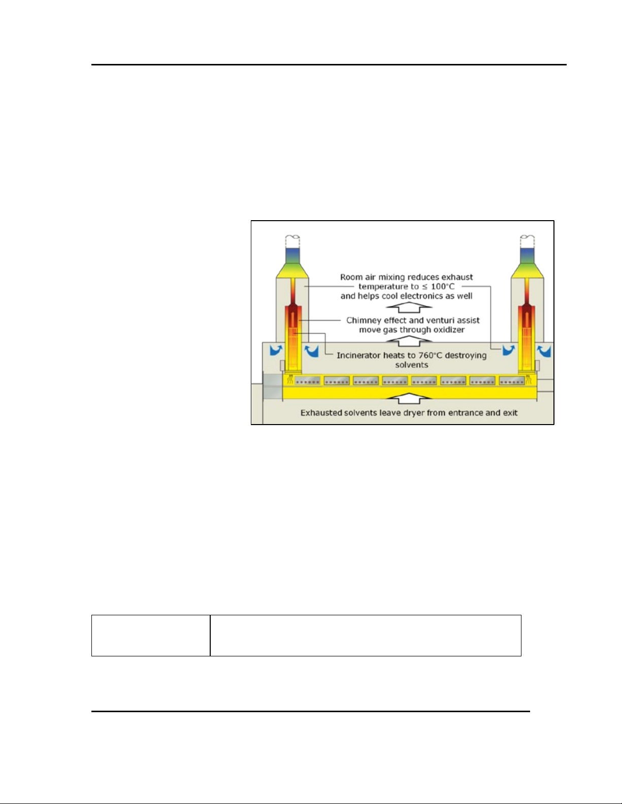
Figure 6. Despatch VOC Thermal Oxidizer Operat i on.
Version 3 25
3.5. VOC Thermal Oxidizer
Paste used in the metallizat ion pro cess can pro d uce harmful byproducts cont aining
volatile organic co mpounds (VOCs) that vaporize into t he at mosphere. In the Unit ed
Sta tes, the Environmental Protection Agency (E P A) requires effective abateme nt of
VOCs.
The Despatch VOC Thermal Oxid izer was des ig ned to eliminat e o ver 99% of VOCs
from gasses exhausted during solar cell manufacturing. Destroying the VOCs using the
Oxidizer eliminates the need to collect and dispose of this waste in a separate process.
The exhaust exiting from t he VOC Oxidizer c ontains only CO2 and water vapor.
The Despatch VOC (Figure 6)
uses elevated temperatures to
cause organic compounds to
co mbust when exposed to
oxygen. Thermal destruction
of most organic compounds
takes place at 350 °C to 450
°C. Thermal oxidizers
typ ic all y maintain a
temperature of 760 °C to
ensure destruc tion of all
VOCs. The process releases
heat and so contributes to
maintaining the t emperat ur e
of the oxidizer.
3.6. Chamber Lift Mechanism
The chamber lift mechanism is o per ated by a pneumatic cylinder and a set of lift c hains
which lift t he chamber into place and seal the upper and lower casings. The pneu matic
cylinder applies a lower pressure to lift the casing. When the casing is within roughly 50
mm, the cylinder applies a higher pressure to seal the casing. Pr essure is c ontinuousl y
applied to the casing while the tool is in Production Mode.
Use of the pneumatic cylinder t o close and op en the chamber
O
All rig hts reserved. No part of th e contents of th is m anual may b e r ep roduced, copied or t r ans mi t t ed i n any for m or b y any
means including graphic, electronic, or mechanical methods or photocopying, recording, or information storage and
retrieval systems without the written permission of Despatch Industries , unless for purchaser's personal use.
means no clamps are required for op erat ion.
Copyright © 2010 by Despatch Industries.
Page 26

THEORY OF OPERATION UltraFlex Drying and Firing Furnace Owner’s Manual
26 Version 3
Operation of the chamber lift is accomplished through the scree ns provided (Section 5.7).
Operating the Chamber Lift mechanism requires that the tool
O
Warnings and alerts for the chamber li ft mec hanis m inc lu d e:
• Audible and on-screen warning before opening
• Alert if the chamber opening or closing does not complete the cycle
O
be in Maintenance Mode.
If the chamber is open, neither heaters nor conveyor will run
(except in Cooldown mode when casing opens 80 mm).
All rig hts reserved. No part of th e contents of th is m anual may b e r ep roduced, copied or t r ans mi t t ed i n any for m or b y any
means including graphic, electronic, or mechanical methods or photocopying, recording, or information storage and
retrieval systems without the written permission of Despatch Industries , unless for purchaser's personal use.
Copyright © 2010 by Despatch Industries.
Page 27
UltraFlex Drying and Firing Furnace Owner’s Manual SOFTWARE & HARDWARE SETUP
Version 3 27
4. Software & Hardware Setup
Always read and underst and Section 2—Safety before
O
4.1. Operation Overview
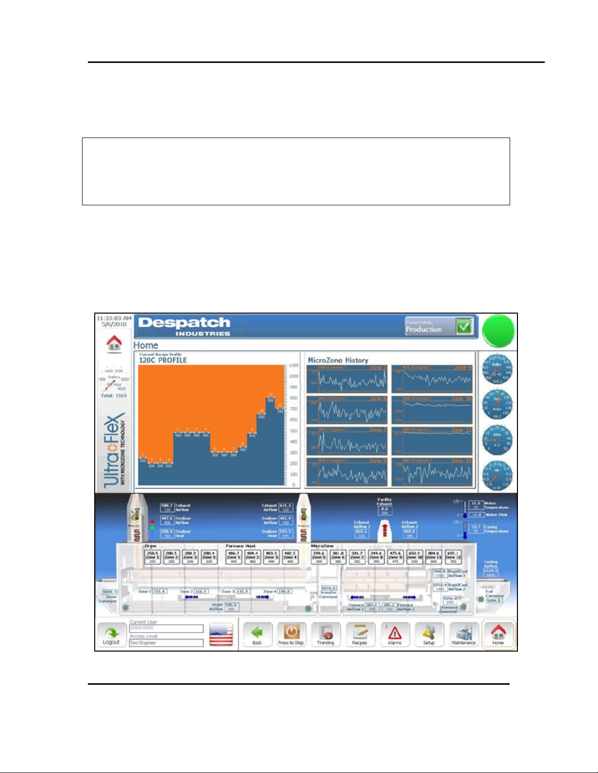
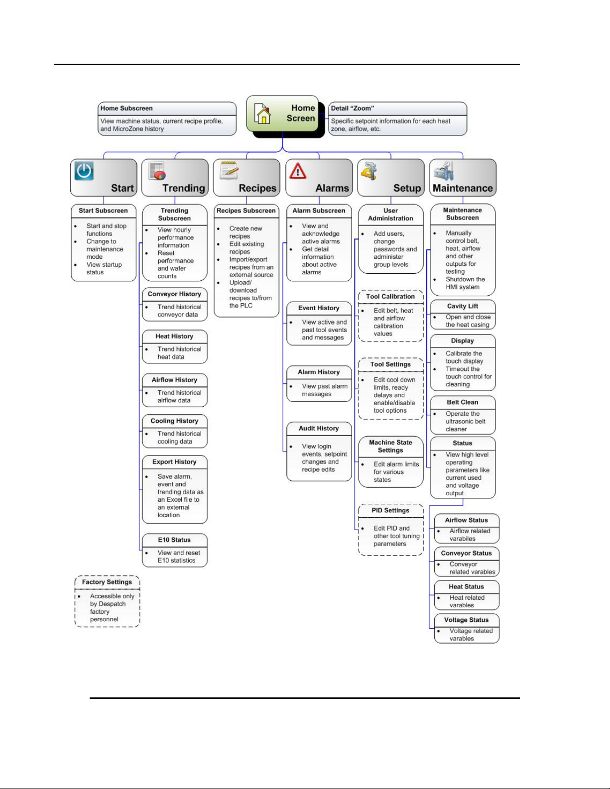
The Ho me Scree n of the UltraFlex Drying and Firing Furnace is the system d ef ault
screen, the screen that app ear s after boot-up ( Figure 7). Navigat e fro m the Home Scr een
to all other screens and modes (including Ready, Stabilization, Cooldown and Idle) used
to operate the UltraFlex Drying and Firing Furnace (Figure 8).
installing, performing maintenance or adjusting the UltraFlex
Drying and Firing Furnace.
Figure 7. Typical Home Screen (UltraFlex).
All rig hts reserved. No part of th e contents of th is m anual may b e r ep roduced, copied or t r ans mi t t ed i n any for m or b y any
means including graphic, electronic, or mechanical methods or photocopying, recording, or information storage and
retrieval systems without the written permission of Despatch Industries , unless for purchaser's personal use.
Copyright © 2010 by Despatch Industries.
Page 28
SOFTWARE & HARDWARE SETUP UltraFlex Drying and Firing Furnace Owner’s Manual
Figure 8. UltraFlex Drying and Firing Furnace Software Navigation.
28 Version 3
All rig hts reserved. No part of th e contents of th is m anual may b e r ep roduced, copied or t r ans mi t t ed i n any for m or b y any
Copyright © 2010 by Despatch Industries.
means including graphic, electronic, or mechanical methods or photocopying, recording, or information storage and
retrieval systems without the written permission of Despatch Industries , unless for purchaser's personal use.
Page 29
UltraFlex Drying and Firing Furnace Owner’s Manual SOFTWARE & HARDWARE SETUP
UltraFlex Furnace
Function
Security Level
Operator
Maintenance
Process
Engineer
Despatch
Users
Load Recipes/Run S yste m
X X X
X
Acknowledge Alarms
X X X
X
Change Languages
X X X
X
Edit Recip es
X X X
Mainte nance Mod e
X X X
Open Chamber
X X X
Enable Remote Access
X X X
Edit Data logging
X X X
Expo rt/I mport Use rs
X
X
Export/Import Calibrations
X
X
Exit System
X
X
Export/I mport Machine
Constants
X
Edit P ID Va lues
X
Version 3 29
4.2. Managing Users
After launching the UltraFlex Drying and Firing Furnace, login to g a in access to syst em
functions.
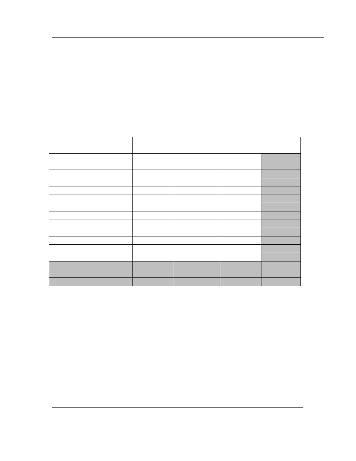
4.2.1. Security Levels
Security to the various functions of the UltraFlex fur nace (Table 1):
Table 1. UltraFlex Security Levels.
All rig hts reserved. No part of th e contents of th is m anual may b e r ep roduced, copied or t r ans mi t t ed i n any for m or b y any
means including graphic, electronic, or mechanical methods or photocopying, recording, or information storage and
retrieval systems without the written permission of Despatch Industries , unless for purchaser's personal use.
Copyright © 2010 by Despatch Industries.
Page 30
SOFTWARE & HARDWARE SETUP UltraFlex Drying and Firing Furnace Owner’s Manual
Setup
Users
Figure 9. Press Setup and
User Information.
Figure 10. Enter or Change User Information with the Setup/User Admini stration Screen.
30 Version 3
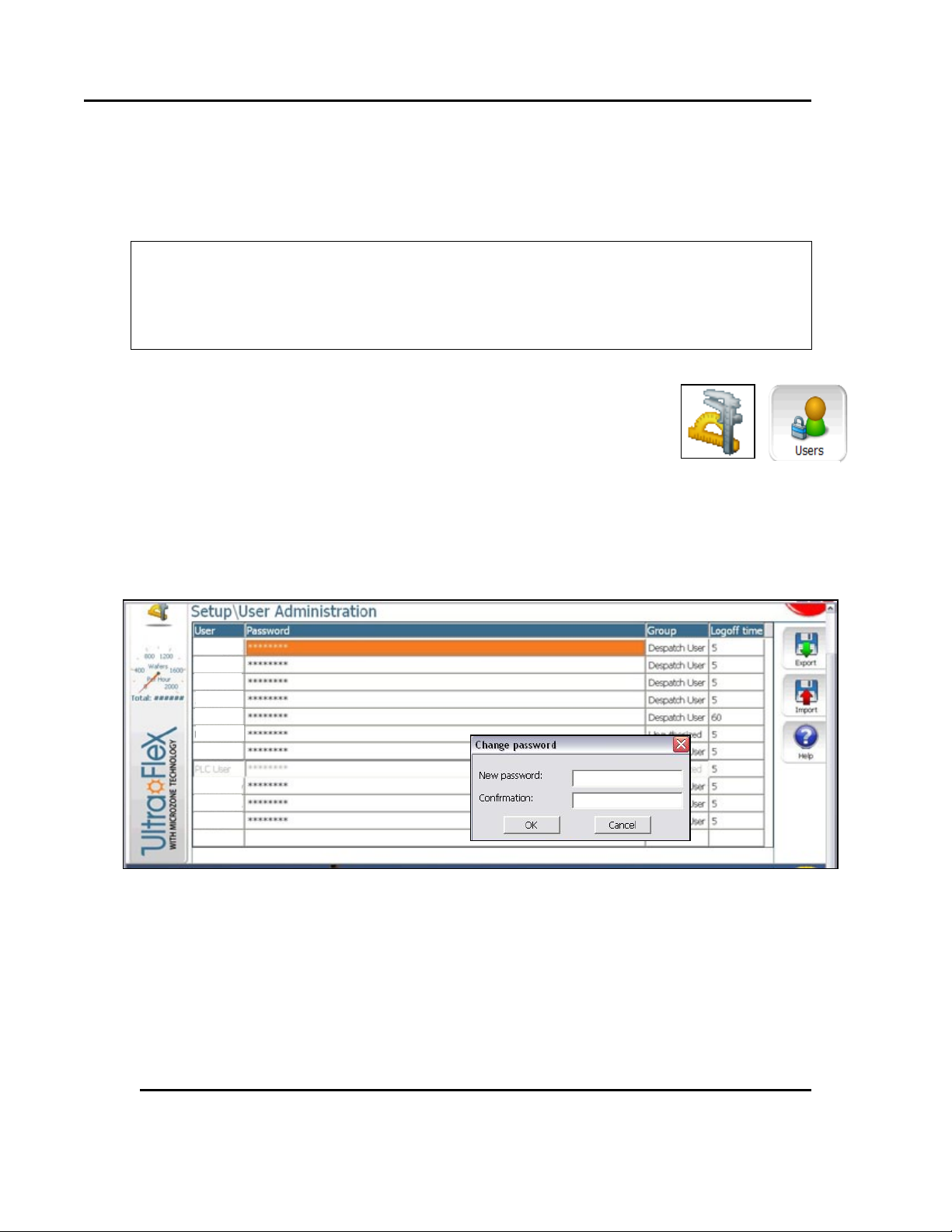
4.2.2. Adding a User or Changing User Privileges
Adding a user or changing user privileges requires use of the user administration
functions. Adding or changing functions includes user names, passwords, user group
identification a nd s pecifying a lo goff time.
The UltraFlex Drying and Firing furnace keeps an audit trail
O
1. From the Home screen, press Setup (Figure 9).
2. Press Users in the User Administrat ion section of the Setup
screen.
a. Press Help at any time for more I n formation
3. Using arrow keys go to the last row on the screen.
4. Double-click (or press Enter) on that row until the blinking
cursor appears
which requires that every change be logged in by a user with a
val id user name.
then Users to Add or Change
a. Ente r Use r name
b. Use t he full first and last name for t he User name entry.
c. Enter New password and Confirmat ion
5. Passwords must be at least four characters
a. Under Group, assign the group appro pr iate to t he tasks required for t he user.
All rig hts reserved. No part of th e contents of th is m anual may b e r ep roduced, copied or t r ans mi t t ed i n any for m or b y any
means including graphic, electronic, or mechanical methods or photocopying, recording, or information storage and
retrieval systems without the written permission of Despatch Industries , unless for purchaser's personal use.
Copyright © 2010 by Despatch Industries.
Page 31

UltraFlex Drying and Firing Furnace Owner’s Manual SOFTWARE & HARDWARE SETUP
UltraFlex Furnace
UltraFlex Furnace Setpoints
Lower Setpoint
Upper Setpoint
Dryer Zones 1-4
25°C
500°C
Furnace Zone 1
25°C
600°C
Furnace Zones 2-4
25°C
750°C
Furnace Zones5-12
25°C
1050°C
Conveyor Speed
100 cm/min
635 cm/min
Oxidizer
25°C
780°C
Version 3 31
b. Enter Logoff t ime (maximu m time the sys te m can remain idle u ntil it
automatic ally log s out.
4.3. Recipe Setup and Optimization
Traditional recipes for solar cell production often adjust conveyor or belt speed to reach
the desired profile. The UltraF lex furna ce uses Mi cr ozone technology to prec isely heat or
cool wafers to the desired t emperat ur e. Microzone technology combines op timized
radiant wavele ngths with custom lamps to provide accurate profiles—independent of
conveyor or belt speed. Microzone technology allows for u nprecedent ed p r ecision in
achieving profiles without changing conveyor or belt speed and thus affecting the rest of
the line.
4.3.1. UltraFlex Furnace Setpoint Ranges
The s e tpoint ranges in Table 2 are based on typical pro d uct temperat u r es rat her than oven
temperatures. Figure 11 shows example f iring zo n e setpoints versus actua l temperatur es
for belt speeds of 508 cm/min and 635 cm/min. Actual zone temperatures (as measured at
the wafer or wafer facsimile) will vary with belt speed and temperature dis p a rity f r om
adjacent zones. The same recipe will produce different measured temperatures at varying
belt speeds. Measure t he t emperat ur e profile following each recipe change.
Lamp zo ne s etpoints les s than 300 °C may adversely affect
O
lamp li fe .
Table 2. UltraFlex Furnace Typical Setpoint Ranges.
Process Area
All rig hts reserved. No part of th e contents of th is m anual may b e r ep roduced, copied or t r ans mi t t ed i n any for m or b y any
means including graphic, electronic, or mechanical methods or photocopying, recording, or information storage and
retrieval systems without the written permission of Despatch Industries , unless for purchaser's personal use.
Copyright © 2010 by Despatch Industries.
Page 32

SOFTWARE & HARDWARE SETUP UltraFlex Drying and Firing Furnace Owner’s Manual
Figure 11. Typical Firing Zone Setpoints vs. Actual Temperatures.
32 Version 3
Copyright © 2010 by Despatch Industries.
All rig hts reserved. No part of th e contents of th is m anual may b e r ep roduced, copied or t r ans mi t t ed i n any for m or b y any
means including graphic, electronic, or mechanical methods or photocopying, recording, or information storage and
retrieval systems without the written permission of Despatch Industries , unless for purchaser's personal use.
Page 33

UltraFlex Drying and Firing Furnace Owner’s Manual SOFTWARE & HARDWARE SETUP
Version 3 33
4.3.2. Optimize Recipe Process with Example
Precise profile cont ro l is achieved using UltraFlex furnace
O
While the UltraFlex furnace o ffers a variety of flexible optimization options, the typical
UltraFlex furnace burno ut-fire-cool pro file includes these steps:
1. Determine process speed ( conveyor minimum and maximum speed), based on:
a. The minimum transport speed based o n the speed of the slowest element in
the production line.
Example Transport Speed:
• W hile y our li ne m ay be different, in this example the printer is the slowest element in
the line with a speed of 1 wafer ever y 2.2 seconds.
.
%
• At 85% loading with a wafer length of 15.6 cm, the minimum transport speed i n the
furnace = 500.5 cm/min.
b. Minimu m a nd maximu m pro cess speed s based o n the recommended process
window supp lie d by the paste co mpany.
Example Minimum & Maximum Process Speed:
In this example, the recommended paste process time of 24-36 seconds includes
heating, burno ut and f iring. The heated length o f the U ltraFlex furnace is 183 cm.
Maximum pr ocess speed:
Minimum process speed:
Microzone technolo gy rather tha n the traditional control of
co nveyor or belt speed .
.
(
(
= /
)
= .
)
All rig hts reserved. No part of th e contents of th is m anual may b e r ep roduced, copied or t r ans mi t t ed i n any for m or b y any
means including graphic, electronic, or mechanical methods or photocopying, recording, or information storage and
retrieval systems without the written permission of Despatch Industries , unless for purchaser's personal use.
Copyright © 2010 by Despatch Industries.
Page 34

SOFTWARE & HARDWARE SETUP UltraFlex Drying and Firing Furnace Owner’s Manual
Number of F iring Zones Required at:
342.9- 381.0 cm/min
(135-150 inch/min)
482.6-558.8 cm/min
(190-220 inch/min)
584.2-635 cm/min
(230-250 inch/min)
Typical Profile
100-125°C/sec
4 5 6
Rapid Firing Profile
125-150°C/sec
3 4 5
Very Rapid Firing Profiles
>150°C/sec
2 3 4
34 Version 3
(
= ./
)
Example: Belt speeds fast er than 500.5 cm/minu te will not
O
increase production speed.
Example Final Process Speed:
Using the process speed (500.5 cm/minute) may limit production. Only conveyor
speeds between 610 cm/minute and 500.5 cm/minute should be considered.
2. Determine the number o f firing zones (Table 3)
Microzone t echno logy allows for an infinite amount of profile change s, ind epe nde nt
of belt speed.
Table 3. Guideline to Determine Number of Firing Zones.
Heating Slopes
Example Number of Firing Zones:
In t his exa mple, a typical profile (100 °C -125°C/second) would require five to six
firing zones.
3. Set airflow in dryer and furnace. Whi le greater volumes of air h elp clean the furnace,
they also elevate electricity consumption and re quire greater exhaust flows.
Example Airflow:
In t his exa mple of a sin gle lane tool, the H M I (inflow ) is s e t to :
• Low end: 190 Lpm
• High end: 380 Lpm
All rig hts reserved. No part of th e contents of th is m anual may b e r ep roduced, copied or t r ans mi t t ed i n any for m or b y any
means including graphic, electronic, or mechanical methods or photocopying, recording, or information storage and
retrieval systems without the written permission of Despatch Industries , unless for purchaser's personal use.
Copyright © 2010 by Despatch Industries.
Page 35

UltraFlex Drying and Firing Furnace Owner’s Manual SOFTWARE & HARDWARE SETUP
Version 3 35
4. Determine single lane o r dual lane cooling rates. Rapid Cooling 1 and Rapid Cooling
2 blow air downward from above t he wa fer and provide top and bo ttom radiant
cooling. The cooling rate depends on fan speeds, cooling water temperature, wafer
mass and belt sp e ed . Faster belt speeds requ ire more cooling, because more mass
needs more co oling. The rapid cooling fans 1 and 2 run between 4% and 100% when
ON. Eve n at a 0% setting ther e will be a 4% minimum speed, which is r equired for
stable fan operation. Typic al cooling rates are 50° to 65°C / second. Adjust fan speeds
to obtain the desired cooling. I f wafers are blown out of position or if excess vibration
is observed, reduce fan speed.
5. Determine burnout temperature
a. In general, lower temperatur es and longer bur no ut times are more p ro du ctive.
But final results are also based on t he past e manuf acturer recommendat ions.
b. If burnout is insufficient, increase t he t emperat ures or reduce belt speed and
use.
Example Burnout Temperature:
In this example, typical burnou t temperatures range fro m more than 300°C to less
than 800°C.
6. Adjust Microzo ne™ t echno logy for desired peak temperature and profile . Microzone
technology is typica lly set to higher setp oints in the center of the firing zones to
optimize heat transfers—based o n shared view fact ors with adjacent zones.
7. Adjust final wafer temperat ure using the exit conveyor coo ling blower volume. On
the Recipe screen (Figure 12):
a. Press Recipe.
b. Press Exit Conveyor Cooling Airflow and adjust blower speeds (to roughly
75%) until the wafers begin to move.
c. Reduce the setpoint by 1-2%.
d. Press Save to use in the currently running recipe.
Expect achievable temperature variations o f 200° C from zone
O
O
All rig hts reserved. No part of th e contents of th is m anual may b e r ep roduced, copied or t r ans mi t t ed i n any for m or b y any
means including graphic, electronic, or mechanical methods or photocopying, recording, or information storage and
retrieval systems without the written permission of Despatch Industries , unless for purchaser's personal use.
to z one.
Microzone techno logy is thermally protected from t he
cumulative te mperat ur e. An alarm is set if the limit temperature
is exceeded.
Copyright © 2010 by Despatch Industries.
Page 36

SOFTWARE & HARDWARE SETUP UltraFlex Drying and Firing Furnace Owner’s Manual
Figure 12. Adjusting Value on Detail Box.
36 Version 3
All rig hts reserved. No part of th e contents of th is m anual may b e r ep roduced, copied or t r ans mi t t ed i n any for m or b y any
means including graphic, electronic, or mechanical methods or photocopying, recording, or information storage and
retrieval systems without the written permission of Despatch Industries , unless for purchaser's personal use.
Copyright © 2010 by Despatch Industries.
Page 37

UltraFlex Drying and Firing Furnace Owner’s Manual SOFTWARE & HARDWARE SETUP
Warning!
Version 3 37
4.4. Dryer/Firing Furnace Airflow Setup
Airflow set up o n th e UltraF lex furnace is essent ial for bot h safet y and process
performance. S p ecific recipe process gas parameter inputs at the HM I depend on accurat e
airflow se tup . A 45-point airflow syste m calibration is perfor med pr ior to shipping the
Ult ra F l ex furnace. This ca libratio n helps ensure accurate airflow thr oug hout the ra nge of
o peration, in all circuit s, and that the flow is accur ately portrayed at the HMI.
Entrance and exit sparges form air curtains that help cont ain VOCs with in the dr yer, for
later pr oce s sing through the VOC T hermal Oxidiz e r (Section 3.5). Only Despatch
per so nnel ma y adjust the Dryer Entrance Sparge Airflow Setpoint and Dryer Exit Sparge
Airflow Setpoint
Dryer Entrance Heat S etpoi nt and Dryer E xit Heat Setpoint set by Despatch personnel both
control a lower set of lamps to provide heat that prevents V OC condensation at dryer
entrance and exit.
4.4.1. Dryer Airflow Setup
to minimize VOCs escaping t he dryer.
Oxidizer airflow setpoints affect the ability of the dryer to draw
out VOCs. Do not tam pe r with oxidizer airflow setpoints without
consulting Despatch.
Process air in the dryer serves primarily as a safety feature to evacuate volatile
compounds in the paste. Configuring airflow in the dryer requires inputting information
about the process, including:
• Amount of paste ap plied
• Solvent concentration
• Throughput
Based on these inputs, the furnace identifies a safe o perating r a nge of flow t o maintain
concentrations below the lower explosive limit (LEL). If loading the furnace creates an
unsafe level of calculated LE L, the machine alerts the operator who mu st either increase
air flow or reduce throughput.
Four recipe inputs determine dryer airflow: MFC1 (Mass Flow Controller for Dryer Zone 1),
MFC 2, MFC 3 and MFC 4. Each inp ut va lu e is clos e -loop controlled with alert and alarm
bands to protect the process and furnace.
Copyright © 2010 by Despatch Industries.
All rig hts reserved. No part of th e contents of th is m anual may b e r ep roduced, copied or t r ans mi t t ed i n any for m or b y any
means including graphic, electronic, or mechanical methods or photocopying, recording, or information storage and
retrieval systems without the written permission of Despatch Industries , unless for purchaser's personal use.
Page 38

SOFTWARE & HARDWARE SETUP UltraFlex Drying and Firing Furnace Owner’s Manual
If
Then
Machine State
Factor > 4
> 25% LEL
Clear
2.25 < Factor < 4
25-45% LEL
Alert
Factor < 2.25
> 45% LEL
Alarm
38 Version 3
After entering the necessar y paste information in the recipe, apply the necessary airflow
values. The formula for calculating LEL is:
(
=
()/) (%)
) 3.328
Table 4 defines t he Factor va lue the Furnace u s es to determine aler t and alar m levels:
Table 4. Determine LEL Alert and Alarm Levels.
Example:
If processing wafers at a rate of 1200 per hour with 1. 2 gr ams of paste and a solvent
concentration of 15% you would need a minimum 259 Lpm of air as a starting point:
0.15
= 259
(
)=
(
4) 1200
3.328
1.2
After establishing the starting point, adjust air flow up or down to operate in the most
efficient manner while maintaining a safe evac uation flow .
Copyright © 2010 by Despatch Industries.
All rig hts reserved. No part of th e contents of th is m anual may b e r ep roduced, copied or t r ans mi t t ed i n any for m or b y any
means including graphic, electronic, or mechanical methods or photocopying, recording, or information storage and
retrieval systems without the written permission of Despatch Industries , unless for purchaser's personal use.
Page 39

UltraFlex Drying and Firing Furnace Owner’s Manual OPERATION
Furnace Status
Process
Navigation
User Identity
Mode
Recipe/Mode
Recipe Name & Current
Screen
Figure 13. UltraFlex Furnace Home Screen.
current setpoint value as the bottom number.
Current process value
Current setpoint value
Version 3 39
5. Operation
5.1. Routine Operati on
Routine ope ration of the UltraFle x furnace involves using the Home Screen (Figure 13).
All f un ctions of the U ltra Flex furnace are available from this screen (Figure 8).
Name
Overview
Bar
Recipe Profile
Indicator
Indicator
O
All rig hts reserved. No part of th e contents of th is m anual may b e r ep roduced, copied or t r ans mi t t ed i n any for m or b y any
means including graphic, electronic, or mechanical methods or photocopying, recording, or information storage and
retrieval systems without the written permission of Despatch Industries , unless for purchaser's personal use.
Graphic conventions used in the UltraFlex furnace show the
current process value as the t op number in the box and the
Copyright © 2010 by Despatch Industries.
Page 40

OPERATION UltraFlex Drying and Firing Furnace Owner’s Manual
40.3
Press boxed area on screen to change data
Press X to close the keypad.
Figure 14. Use On-Screen Keypad or Keyboard to Enter Data.
40 Version 3
5.1.1. Overview
5.1.1.1. Using the UltraFlex Furnace Touch Screen I nterface
The UltraFlex furnace t ouch screen is a highly sensitive screen that allows direct
interaction with the dat a. P r ess firmly on any boxed ar ea to change dat a using the onscreen keypad or keyboard ( Figure 14). Note that the on-scree n ke ypad and keyboard can
be grabbed, moved to different parts of the screen and res ized.
All rig hts reserved. No part of th e contents of th is m anual may b e r ep roduced, copied or t r ans mi t t ed i n any for m or b y any
means including graphic, electronic, or mechanical methods or photocopying, recording, or information storage and
retrieval systems without the written permission of Despatch Industries , unless for purchaser's personal use.
Copyright © 2010 by Despatch Industries.
Page 41

UltraFlex Drying and Firing Furnace Owner’s Manual OPERATION
Fine-tine upper and lower parameters
On-screen boxes indicate
values.
Figure 15. Using On-Screen Controls.
Version 3 41
5.1.1.2. Using On-Screen Controls
Adjust upper and lower limit on screens to focus on specific readings or trending
information (Figure 15). Any box on the screen ind icates a p lace where a user can input
information.
to focus on desired curv e.
areas where users can input
5.1.1.3. Process Overview
The top third of the Home Screen provides at-a-glance statu s of the current r ecipe
including the current p ro file, profiles of each of the eight zones using Micro zone
technology and current elect r ica l use (Figure 16).
All rig hts reserved. No part of th e contents of th is m anual may b e r ep roduced, copied or t r ans mi t t ed i n any for m or b y any
means including graphic, electronic, or mechanical methods or photocopying, recording, or information storage and
retrieval systems without the written permission of Despatch Industries , unless for purchaser's personal use.
Copyright © 2010 by Despatch Industries.
Page 42

OPERATION UltraFlex Drying and Firing Furnace Owner’s Manual
Monitor current r eci pe pr ofile
Monitor zones 5-12 of the Ult r aFlex furnace. Use Microzone technol ogy to
Monitor incomi ng power available to the furnace using volt age, amper age, kilovolts,
Mode Indicat or:
Blue: Cooldown Mode
Figure 16. UltraFlex Furnace Home Screen—Process Overview.
42 Version 3
• Green: Production Mode
• Yellow: St abilization Mode (Percent pr ogr ess gauge displayed only during Stabilization Mode)
• Red: Idle Mode
•
setpoints for eac h zone.
fine-tune firing times in each zone independent of belt speed.
frequency and power fac tor.
Current tool mode
5.1.1.4. Furnace Status
The middle portion of the Home Screen pr e sents a schemat ic perspective of the UltraFlex
furnace showing actual and current setpoint values for each of the zones, belt speed s,
exhaust values and ot her cr it ical values (Figure 17). Touch any boxed area for a specific
detail screen to rep lace the pro cess overview (Figure 18).
Copyright © 2010 by Despatch Industries.
All rig hts reserved. No part of th e contents of th is m anual may b e r ep roduced, copied or t r ans mi t t ed i n any for m or b y any
means including graphic, electronic, or mechanical methods or photocopying, recording, or information storage and
retrieval systems without the written permission of Despatch Industries , unless for purchaser's personal use.
Page 43

UltraFlex Drying and Firing Furnace Owner’s Manual OPERATION
Current setpoint value
Current process v alue
Figure 17. UltraFlex Furnace Home Screen—Furnace Status.
Figure 18. Typical Detail Screen for Furnace Temperature Zone 1.
Version 3 43
All rig hts reserved. No part of th e contents of th is m anual may b e r ep roduced, copied or t r ans mi t t ed i n any for m or b y any
means including graphic, electronic, or mechanical methods or photocopying, recording, or information storage and
retrieval systems without the written permission of Despatch Industries , unless for purchaser's personal use.
Copyright © 2010 by Despatch Industries.
Page 44

OPERATION UltraFlex Drying and Firing Furnace Owner’s Manual
Mode
Primary Purpose
User
Idle Mode
The furnace is powered but a waiting
Operator, Supervisor
Stabilizati on M ode
The furnace is prepari ng to run a
Operator, Supervisor
Production Mode
Primary mode for running a recipe and
Operator, Supervisor
Cooldown Mode
Production m ode has been shut down
Operator, Supervisor
Maintenance Mode
Allows maintenanc e per sonnel to
Supervisor, Maintenance
Figure 19. UltraFlex Furnace Home Screen—Navigation Bar.
44 Version 3
5.1.1.5. Navigation Bar
The navig a tion bar on the UltraFlex furnace p r ovides t he u ser login as wel l as but t ons for
trending, rec ipes, alarms, setup, maintenance and the return to the home scree n (Figure
19). Press to Start on t he nav igation ba r d isplays a screen tha t allows the furnace to be
started.
5.1.1.6. UltraFlex Dry in g and Fi r ing Fur n ac e Modes
The UltraFlex Drying and Firing Furnace employs five modes to gove rn it s use (Table 5).
Operating the UltraF le x furnace usually in volv es primarily the Production mode along
wit h the Idle and Cooldown modes. The Maint ena nc e mode is not typic ally used by the
operator.
Table 5. UltraFlex Firing & Drying Furnace Modes.
instruction.
recipe.
producing wafers.
in anticipation of a new recipe, a new
production schedul e or m aintenance.
maintain or repair the furnace.
NOTE: The furnace cannot run in
Production mode while in Maintenance
mode.
Personnel
All rig hts reserved. No part of th e contents of th is m anual may b e r ep roduced, copied or t r ans mi t t ed i n any for m or b y any
means including graphic, electronic, or mechanical methods or photocopying, recording, or information storage and
retrieval systems without the written permission of Despatch Industries , unless for purchaser's personal use.
Copyright © 2010 by Despatch Industries.
Page 45

UltraFlex Drying and Firing Furnace Owner’s Manual OPERATION
Version 3 45
5.1.2. Navigating the Home Screen
After logging on with a Use r name and Password (as established by the administrat or ) the
Home screen serve s as t he best window for monito ring the entire process. From the
Home Screen, the user can navigat e to these o per ations:
• Run: Start and stop the tool.
• Trending: Pr ov id es his tor ic al information and allows for the exporting of production
historical data. Trending screens have user -configurable upper and lower par ameters
for precise windows into performance.
• Recipes: Allows for importing and exporting of recipes, along with setup screens fo r
each of the recipes.
• Alarms: Lists ala rm times, dat e s a nd more info rmation.
• Setup: Allows for us er ad ministration, importing and expo rting of recipes, ca libratio n
and other set tings and setup funct ions. Generally used only at the initial stages of
furnace set up.
• Maintenance: Pro vide s a safe, non-production mode for furnace maintenance
functions. Includes cleaning and calibration functions.
All rig hts reserved. No part of th e contents of th is m anual may b e r ep roduced, copied or t r ans mi t t ed i n any for m or b y any
Copyright © 2010 by Despatch Industries.
means including graphic, electronic, or mechanical methods or photocopying, recording, or information storage and
retrieval systems without the written permission of Despatch Industries , unless for purchaser's personal use.
Page 46

OPERATION UltraFlex Drying and Firing Furnace Owner’s Manual
Current
Trending
Press to
E10
Figure 20. Trending Screen.
46 Version 3
5.1.3. Trending Screen
The Trending screen provides opt ions for access in g and downloading historical values
for c ritica l sys tems in the Ultr aFle x fur nace (Figure 20), inclu ding the conveyors, heat
and airf low. Eac h trending s creen d is plays value s , setpoints and o utputs in relation to
conveyor speed. Exporting data logs, records or histories typically takes ro ughly 20
minutes, depending on the amount of data. Available data may range from one to several
weeks.
wafer
output
counter
options
Statistics
export
data log
Press Conveyor, Heat, Airflow or Cooling for detai led trending screens. For inst a nc e , press
Heat and the n Heat Zone 1 to access the Histor y Trending/Furnace Zone 1 screen (Figure
21). Further trending opt ions are listed on the right side of the screen. See Section 5.3 for
more info rmation abo ut wo rking with the tre nding s c reen.
All rig hts reserved. No part of th e contents of th is m anual may b e r ep roduced, copied or t r ans mi t t ed i n any for m or b y any
means including graphic, electronic, or mechanical methods or photocopying, recording, or information storage and
retrieval systems without the written permission of Despatch Industries , unless for purchaser's personal use.
Copyright © 2010 by Despatch Industries.
Page 47

UltraFlex Drying and Firing Furnace Owner’s Manual OPERATION
Further
Controls
Figure 21. History Trendi ng / Furnac e Zone 1 Screen.
Version 3 47
trending
options
for
viewing
screens
All rig hts reserved. No part of th e contents of th is m anual may b e r ep roduced, copied or t r ans mi t t ed i n any for m or b y any
means including graphic, electronic, or mechanical methods or photocopying, recording, or information storage and
retrieval systems without the written permission of Despatch Industries , unless for purchaser's personal use.
Copyright © 2010 by Despatch Industries.
Page 48

OPERATION UltraFlex Drying and Firing Furnace Owner’s Manual
Figure 22. Recipes Screen and Pop-up Screen for Parameters Descriptions.
48 Version 3
5.1.4. Recipe Screen
The Recipes screen allows importing new recipes from other storag e devices as wel l as
allowing new recipes to be enter ed manuall y, para met er -by-parameter. Press Parameter
Descriptions
information about working with recipes.
for more information about par ameters (Figure 22). See Section 5.4for more
Copyright © 2010 by Despatch Industries.
All rig hts reserved. No part of th e contents of th is m anual may b e r ep roduced, copied or t r ans mi t t ed i n any for m or b y any
means including graphic, electronic, or mechanical methods or photocopying, recording, or information storage and
retrieval systems without the written permission of Despatch Industries , unless for purchaser's personal use.
Page 49

UltraFlex Drying and Firing Furnace Owner’s Manual OPERATION
Number of active alarms in
upper left corner
O
Figure 23. Alarms Screen and Close-up of Unacknowledged Al arms.
Version 3 49
5.1.5. Alarm Screen
The Alarms screen displays active or unacknowledged alarms (Figure 23). Press
Acknowledge to recognize and disarm the highlighted alarm. Press Info fo r a text bo x to
po p with further information abou t t he alarm. Pres s Alarm History to disp lay recent
alarms ( Figure 24). The Alarm History screen uses color coding to display four levels:
• Equipment Safety (Red)
• Irreco verable Error (Black)
• Parameter Control Error (Blue)
• Attention Flags (Yellow)
See Section 5.5 for more infor mation about working with the alarm screen. Whe n a
system event oc c urs (Figure 25), the operator should contact maintenance personnel or
the Process engineer.
There is a ten second delay betw een when a zone turns color
and when the alarm is annunciated.
All rig hts reserved. No part of th e contents of th is m anual may b e r ep roduced, copied or t r ans mi t t ed i n any for m or b y any
means including graphic, electronic, or mechanical methods or photocopying, recording, or information storage and
retrieval systems without the written permission of Despatch Industries , unless for purchaser's personal use.
Copyright © 2010 by Despatch Industries.
Page 50

OPERATION UltraFlex Drying and Firing Furnace Owner’s Manual
Figure 24. Alarm History Screen.
Figure 25. System Event Alarm Screen.
50 Version 3
All rig hts reserved. No part of th e contents of th is m anual may b e r ep roduced, copied or t r ans mi t t ed i n any for m or b y any
means including graphic, electronic, or mechanical methods or photocopying, recording, or information storage and
retrieval systems without the written permission of Despatch Industries , unless for purchaser's personal use.
Copyright © 2010 by Despatch Industries.
Page 51

UltraFlex Drying and Firing Furnace Owner’s Manual OPERATION
Warning!
Figure 26. Setup Screen.
Version 3 51
5.1.6. Setup Screen
The Setup screen provides options for readying the UltraFlex furnace for production
(Figure 26). The Setup screen is typically used at installation and then not aga in except
fo r ad justme nt s. Find information about manag ing u s ers with the Setup screen in the
Software and Hardwar e S etu p sec tion (4.2). See Section 5.6 for more information about
wo rking with the setup screen.
Oxidizer airflow setpoints affect the ability of the dryer to draw
out VOCs. Do not tamper with oxidizer airflow setpoints without
consulting Despatch.
5.1.7. Maintenance Screen
The Maintenance scree n provides access to switches to isolate and test individual
elements of the UltraFlex furnace (Figure 27). A red button indicates the system is
currently disabled. A green button indicates the system is currently enabled. A square red
button may appear to “Clear fault.”
All rig hts reserved. No part of th e contents of th is m anual may b e r ep roduced, copied or t r ans mi t t ed i n any for m or b y any
means including graphic, electronic, or mechanical methods or photocopying, recording, or information storage and
retrieval systems without the written permission of Despatch Industries , unless for purchaser's personal use.
Copyright © 2010 by Despatch Industries.
Page 52

OPERATION UltraFlex Drying and Firing Furnace Owner’s Manual
Maintenance
Maintenance Sc r een Closeup
Figure 27. Maintenance Screen with Close-up.
52 Version 3
• Airflow Valve Bank: With the top switch set to Manual, enable any one system
and read the pressure o f that system at the bott om of the column. The pressure
reflects the cumulat ive pressur e of all enabled systems.
• Furnace Airflow: Enable, disab le o r change setpo int.
• Zones 1-12: Cha nge setpoints
• Misc. Outputs: Safety Relay OK removes power from the UltraFlex furnace if not
enabled. Enable or disabl e heat, lights and horn.
Screen
All rig hts reserved. No part of th e contents of th is m anual may b e r ep roduced, copied or t r ans mi t t ed i n any for m or b y any
means including graphic, electronic, or mechanical methods or photocopying, recording, or information storage and
retrieval systems without the written permission of Despatch Industries , unless for purchaser's personal use.
Copyright © 2010 by Despatch Industries.
Page 53

UltraFlex Drying and Firing Furnace Owner’s Manual OPERATION
Figure 28. Confirm LEL Settings Dial ogue Window.
Version 3 53
5.2. Startup and Run the UltraFlex Drying and Firing Furnace
Production Mode controls the way the tool functions in day-to-day operation. This
section shows how to get to Production Mode.
Automati c LEL Calculation Prior to Production Mode
Before completing any star tup procedure, the UltraFlex furnace
automatically calculates the wafers per hour it can safely
produce without exceed ing preset Lo w er Explosive L imits
(LEL).
Before any Start u p procedu r e, be prepar ed to enter these values
(Figure 30):
• Weight of paste (per wafer) in grams
• Percentage of volatile s olvent (by weight) in the paste.
O
Consult the Mater ial Data S afet y Sheets ( MSDS) provided
by the paste manufacturer .
Using these values, t he UltraFle x fur nace calcu lat es:
• Wafers per hour threshold that exceeds 25 perce nt LEL.
This value generat es a warn ing alar m (Figure 28).
• Wafers per hour threshold that exceeds 40 perce nt LEL.
This value stops the Dryer conveyor from running.
All rig hts reserved. No part of th e contents of th is m anual may b e r ep roduced, copied or t r ans mi t t ed i n any for m or b y any
means including graphic, electronic, or mechanical methods or photocopying, recording, or information storage and
retrieval systems without the written permission of Despatch Industries , unless for purchaser's personal use.
Copyright © 2010 by Despatch Industries.
Page 54

OPERATION UltraFlex Drying and Firing Furnace Owner’s Manual
Figure 29. Start Prod uction Mode from Idle Mode.
Figure 31. Stabilization Mode.
Figure 30. LEL Dialogue Window.
54 Version 3
5.2.1. Starting from Idle Mode
1. From the Idle Mode Home screen press Press
to Start
2. Press Start to open the LEL Dialogue Window
(Figure 30):
3. Press Start to start the tool and enter Stabilization Mod e.
to load the Run window (Figure 29).
a. The currently loaded recipe is
highlighted in the Recipe/Mo de
indicator box.
b. Select another recipe as needed fro m
the drop dow n menu.
c. To set a new recipe, press Recipes to
go to the Recipes screen. Or use the
Recipe Selection pull-down me nu .
a. Enter the current paste weight
b. Enter the total per centage volatility.
c. Check Material Data Safety Sheets (MSDS ) as necessary.
All rig hts reserved. No part of th e contents of th is m anual may b e r ep roduced, copied or t r ans mi t t ed i n any for m or b y any
means including graphic, electronic, or mechanical methods or photocopying, recording, or information storage and
retrieval systems without the written permission of Despatch Industries , unless for purchaser's personal use.
Copyright © 2010 by Despatch Industries.
Page 55

UltraFlex Drying and Firing Furnace Owner’s Manual OPERATION
Figure 32. Tool in Production Mode.
Version 3 55
4. Startup status is indicated for each compo nent in the R un w indow. The too l is ready
when ope rating within the p ro c ess w indow limits for the ready delay setting (Figure
32). The default ready delay
sett ing is t hr ee minu t e s. When
all the tool components have
stabilized, the too l enter s
Production Mode.
5.2.2. Stopping from Production Mode
1. From the Product ion Mode home scree n, press Press to Stop to o pen t he Run
window.
2. Press Cooldown (Figure 32).
3. For t ypical tool shut down, press Normal. Typical tool shut down process includes:
a. Heat shuts off first.
b. Exhaust airflow increases to 100 percent.
c. When temperature drops below the Cooldown threshold, airflow and
conveyors stop and the tool enters Idle Mode.
4. For rapid tool shut down, press Rapid. Rapid tool shut down process includes:
a. Heat shuts off first.
b. The chamber opens roughly 80 mm.
Though the chamber opens roughly 80 mm, the opening
O
c. Exhaust airflow increases to 100 percent.
d. When te mp e rature drops below the Co oldo wn threshold, airflow a nd
conveyors stop and the tool enters Idle Mode.
remains covered by the chamber casing.
All rig hts reserved. No part of th e contents of th is m anual may b e r ep roduced, copied or t r ans mi t t ed i n any for m or b y any
means including graphic, electronic, or mechanical methods or photocopying, recording, or information storage and
retrieval systems without the written permission of Despatch Industries , unless for purchaser's personal use.
Copyright © 2010 by Despatch Industries.
Page 56

OPERATION UltraFlex Drying and Firing Furnace Owner’s Manual
O
Mode.
Figure 33. Trending Main Screen.
56 Version 3
5.2.3. Entering Maintenance Mode from Idle Mode
Maintenance Mode is not intended for production purposes.
1. From the Product ion Mode home scree n, press Press to Stop to open the Run
window.
2. Press Maintenance Mode to open the Maintenance window.
5.2.4. Entering Maintenance Mode fro m Production or Cooldown Mode
Maintenance Mode is not intended for production purposes.
O
Maintenance Mode can only be entered through the Idle
5.3. Working wit h Trendin g
Trending (Figure 33) allows collected data to be viewed using customizable scales. Each
o f the major UltraFlex furnace syste m s is availa ble for data monitoring, with heat ,
air f low a nd co oling data shown in c ompa rison t o conveyor s peed .
All rig hts reserved. No part of th e contents of th is m anual may b e r ep roduced, copied or t r ans mi t t ed i n any for m or b y any
means including graphic, electronic, or mechanical methods or photocopying, recording, or information storage and
retrieval systems without the written permission of Despatch Industries , unless for purchaser's personal use.
Copyright © 2010 by Despatch Industries.
Page 57

UltraFlex Drying and Firing Furnace Owner’s Manual OPERATION
Figure 34. Conveyor Trending Screen.
Version 3 57
5.3.1. Working with Hourly Performance
The Hourly Performance section of the Trending screen provides wafer t hroughput
performance for a variety of t ime ranges (Figure 33). Press Reset to zero all counters.
5.3.2. Conveyor
Press Conveyor to display current data points for the conveyor (Figure 34). Adjust upper
and lower parameters us ing on-screen controls (See Section 5.1.1.2 for more information
ab out on-screen contro ls).
All rig hts reserved. No part of th e contents of th is m anual may b e r ep roduced, copied or t r ans mi t t ed i n any for m or b y any
means including graphic, electronic, or mechanical methods or photocopying, recording, or information storage and
retrieval systems without the written permission of Despatch Industries , unless for purchaser's personal use.
Copyright © 2010 by Despatch Industries.
Page 58

OPERATION UltraFlex Drying and Firing Furnace Owner’s Manual
Figure 35. Heat Trending Screen.
58 Version 3
5.3.3. Heat
Press Heat to display current temperature data points compared with conveyor speed.
Choose the desired heat zone from the choices on the right of the screen (Figure 35).
Adjust upper and lower parameters using on-screen controls (See S ection 5.1.1.2 for
mo r e i n forma tio n about on-screen contro ls).
Copyright © 2010 by Despatch Industries.
All rig hts reserved. No part of th e contents of th is m anual may b e r ep roduced, copied or t r ans mi t t ed i n any for m or b y any
means including graphic, electronic, or mechanical methods or photocopying, recording, or information storage and
retrieval systems without the written permission of Despatch Industries , unless for purchaser's personal use.
Page 59

UltraFlex Drying and Firing Furnace Owner’s Manual OPERATION
Figure 36. Air flow Trending Screen.
Version 3 59
5.3.4. Airflow
Press Airflow to display current data points co mpared with conveyor speed. Choose the
desired section fro m the choices o n t he right of the screen (Figure 36). Adjust upper and
lower parameters us ing on-screen controls (See Section 5.1.1.2 for more information
ab out on-screen contro ls).
Copyright © 2010 by Despatch Industries.
All rig hts reserved. No part of th e contents of th is m anual may b e r ep roduced, copied or t r ans mi t t ed i n any for m or b y any
means including graphic, electronic, or mechanical methods or photocopying, recording, or information storage and
retrieval systems without the written permission of Despatch Industries , unless for purchaser's personal use.
Page 60

OPERATION UltraFlex Drying and Firing Furnace Owner’s Manual
Figure 37. Cooling Trending Screen.
60 Version 3
5.3.5. Cooling
Press Cooling to display current data points compared with conveyor speed (Figure 37).
Adjust upper and lower parameters using on-screen controls (See S ection 5.1.1.2 for
mo r e i n forma tion about on-screen controls).
All rig hts reserved. No part of th e contents of th is m anual may b e r ep roduced, copied or t r ans mi t t ed i n any for m or b y any
means including graphic, electronic, or mechanical methods or photocopying, recording, or information storage and
retrieval systems without the written permission of Despatch Industries , unless for purchaser's personal use.
Copyright © 2010 by Despatch Industries.
Page 61

UltraFlex Drying and Firing Furnace Owner’s Manual OPERATION
Caution!
Version 3 61
5.3.6. Data
Press Data to display the screen (Figure 38) for downloading Event History, Alarm
History
USB port for downloading recipes and exporting data. Reserve the rear USB port for data
logging (Figure 39).
, Trending History or Diagnostic History data. Despat ch recommends the fro nt
Use only the rear USB port for dataloggin g purpo ses. T he rear
USB port is more secure for longer-term use and provides less
opportunity for the memory stick to be dislodged.
Exporting data from the UltraF le x fur nace requires a blank 4GB
USB memory stick be inserted into the front USB port (Figure
O
39). 4GB i s the maximum size for the memory stick t hat ca n
be inserted into either USB port.
Do not lea ve the ext erna l memory stick in the fro nt USB port
O
O
during normal operation or log data may be stored to it (and
thus not stored to the usual rear memory unit).
Data logging will cease during data exporting operat ion.
Copyright © 2010 by Despatch Industries.
All rig hts reserved. No part of th e contents of th is m anual may b e r ep roduced, copied or t r ans mi t t ed i n any for m or b y any
means including graphic, electronic, or mechanical methods or photocopying, recording, or information storage and
retrieval systems without the written permission of Despatch Industries , unless for purchaser's personal use.
Page 62

OPERATION UltraFlex Drying and Firing Furnace Owner’s Manual
Close-up of
Figure 38. Data Logging Screen.
Figure 39. Front and Rear USB Ports.
Front
Close-up of
Rear
62 Version 3
Front USB Port
Rear USB Port
All rig hts reserved. No part of th e contents of th is m anual may b e r ep roduced, copied or t r ans mi t t ed i n any for m or b y any
means including graphic, electronic, or mechanical methods or photocopying, recording, or information storage and
retrieval systems without the written permission of Despatch Industries , unless for purchaser's personal use.
USB Port
Copyright © 2010 by Despatch Industries.
USB Port
Page 63

UltraFlex Drying and Firing Furnace Owner’s Manual OPERATION
Figure 40. E10 Statistics Screen.
Version 3 63
5.3.7. E10 Statistics
E10 Reporting defaults at Enable. Use t he drop down menu to switch to Disable if desire d
(Figure 40).
5.3.7.1. E10 States
Press E10 Stats from the Trending scree n to display the E10 Stat istics screen ( Figure 40).
E10 St atistics uses t hese six states to organize and communicate the UltraFlex furnace
uptime details:
• Productive State (Productive Time): Time the tool is performing it s intended
function. An example o f Productive Time might be regular production.
• Standby State (Standby Time): Time the tool is ready for the Productive State, but
is not being o perate d. An examp le of Sta ndby Time might be w hen t he op erator is
una vailable, perhaps on break or at lunch.
• Engineering State (Engineering Time): Time the tool is ready for the Prod uct ive
State but is instead op er ated to conduct engineering tests
• Scheduled Downtime State (Scheduled Downtime): Time the to ol is not availa b le
to perform its intended funct ion because o f planned downtime events
• Unscheduled Downtime Stat e (Unscheduled Downtime): Time the t ool is not in a
co ndit ion to perfor m its intend e d fu nc tion bec a use of unplan ned downtime eve nts
• Non-Scheduled State (Nonscheduled Time): Time the tool is not scheduled to be
used for production. An examp le o f N onscheduled Time might be an unworked
shift.
All rig hts reserved. No part of th e contents of th is m anual may b e r ep roduced, copied or t r ans mi t t ed i n any for m or b y any
means including graphic, electronic, or mechanical methods or photocopying, recording, or information storage and
retrieval systems without the written permission of Despatch Industries , unless for purchaser's personal use.
Copyright © 2010 by Despatch Industries.
Page 64

OPERATION UltraFlex Drying and Firing Furnace Owner’s Manual
Figure 41. Operator Selects Equ ipment State.
64 Version 3
For more infor mation on E10 Statistics, refer to the official document at www.semi.org:
SEMI E10-0304E10 Specification for Definition and Measurement of Equipment
Reliability, Availability, and Maintainability (RAM).
5.3.7.2. Operator Initiated States
Wit h every to ol mode change, a dialogue window displays so the o per ator can choo se the
current E10 stat e (Figure 41).
5.4. Working with Recipes
The UltraFlex furnace interior is a combination of lamps, materials and geometry that
result in a unique furnace environment. Furnace-zone temperature setpoints a pproximate
the temperature desired at t he wafer. Fo r initial rec ipe ge neration, verify t he setpoint
temperatures and ad just using the thermocouple-fixtured substrat e designed specif ica l ly
for the UltraFlex furnace env ironment (available from Despatch). Use cell electr ical
performance measurements and other metrology to arrive at an optimal thermal recipe.
Contact Despat ch for assist ance w it h Process Engineering and optimiza tion nee ds.
All rig hts reserved. No part of th e contents of th is m anual may b e r ep roduced, copied or t r ans mi t t ed i n any for m or b y any
means including graphic, electronic, or mechanical methods or photocopying, recording, or information storage and
retrieval systems without the written permission of Despatch Industries , unless for purchaser's personal use.
Copyright © 2010 by Despatch Industries.
Page 65

UltraFlex Drying and Firing Furnace Owner’s Manual OPERATION
Add a new recipe by pressing
Press arrow to reveal
available reci pes.
Status bar
Figure 42. Work with Existing or New Recipes Using the Recipe Scree n.
Version 3 65
5.4.1. Enter a New Recipe
Enter a new recipe by pressing New on the Recipe screen and updating the value for each
parameter from the defau lt values ( Figure 43). Recipe s typically include a setpoint, a high
and low a larm devi ation, and high and low process dev iation for each parameter.
New and then adding v alues
parameter by parameter.
Note that recipes must be named and sa ved to be retained. Rec ipe s not saved wi l l be lost.
5.4.2. Working with Existing Recipes
5.4.2.1. Load Existing Recipe
Press the down arro w (Figure 42) to display recipe s c urr e ntly a vailable and p ic k the
desired recipe. Recipe w ill load all parameters.
All rig hts reserved. No part of th e contents of th is m anual may b e r ep roduced, copied or t r ans mi t t ed i n any for m or b y any
means including graphic, electronic, or mechanical methods or photocopying, recording, or information storage and
retrieval systems without the written permission of Despatch Industries , unless for purchaser's personal use.
Copyright © 2010 by Despatch Industries.
Page 66

OPERATION UltraFlex Drying and Firing Furnace Owner’s Manual
66 Version 3
5.4.2.2. Import a Recipe
Import existing rec ipes into the UltraFlex furnace using Import recipes from disk from the
Recipes screen (Figure 43). T he curr ent r ecipe ru nning on the UltraFlex furnace can also
be uploaded for editing (press Upload from PLC).
Recipes imported from disk should be in CSV format. See the
“Saved Recipe” Microsoft E xcel file you received with your
UltraFlex furnace.
O
5.4.2.3. Change a Recipe Value
Changing a recipe value requ ires t hat t he user enter their password and comment about
the c hange (Figure 43). T his log in/c omment p r ocess allows changes to be carefully
tracked and provides useful information when examining the logs.
All rig hts reserved. No part of th e contents of th is m anual may b e r ep roduced, copied or t r ans mi t t ed i n any for m or b y any
Copyright © 2010 by Despatch Industries.
means including graphic, electronic, or mechanical methods or photocopying, recording, or information storage and
retrieval systems without the written permission of Despatch Industries , unless for purchaser's personal use.
Page 67

UltraFlex Drying and Firing Furnace Owner’s Manual OPERATION
Figure 43. Recipe with Comment Dialogue Box Open.
Version 3 67
5.4.2.4. Export a Recipe
Export recipes by pressing Export recipes to disk. Exported recipes are saved as CSV
files which c an be opene d with M ic ro s oft E xcel (Figure 44). S ave a recipe by pressing
Save. Download a rec ipe for use by the UltraFle x fur nace b y pressing Download to PLC.
Save any changes to Recipe values pri or to downloading to
O
the PLC.
All rig hts reserved. No part of th e contents of th is m anual may b e r ep roduced, copied or t r ans mi t t ed i n any for m or b y any
means including graphic, electronic, or mechanical methods or photocopying, recording, or information storage and
retrieval systems without the written permission of Despatch Industries , unless for purchaser's personal use.
Copyright © 2010 by Despatch Industries.
Page 68

OPERATION UltraFlex Drying and Firing Furnace Owner’s Manual
on the CSV file must not be altered.
Figure 44. Recipe File Saved as CSV File.
68 Version 3
5.4.2.5. Edit a Recipe on a PC
Recipes from the UltraF lex furnace ca n be expor ted as CSV files and opened with
Microsoft Excel. Recipe s files use tw o columns (Figure 44):
• Column A is the name of the recipe item
• Column B is the value of the named recipe item
Certain UltraFl ex furnace information must not be altered for
O
To change a value, type the new value in the appropriate cell.
To add a recipe:
1. Copy all the data from a column that close ly matches the new recipe values.
2. Give the recipe a new name (Row 3, Column 1)
3. Give the recipe a new number (Row 4 , Column 1)
4. Edit the valu e s and s ave the fi le.
correct performance.
Rows 1 and 2 on the CSV file must not be altered. Column 4
Use unique names for recipes. Unless recipes are given
O
unique names, they will overwrite previous recipes with that
name.
All rig hts reserved. No part of th e contents of th is m anual may b e r ep roduced, copied or t r ans mi t t ed i n any for m or b y any
means including graphic, electronic, or mechanical methods or photocopying, recording, or information storage and
retrieval systems without the written permission of Despatch Industries , unless for purchaser's personal use.
Copyright © 2010 by Despatch Industries.
Page 69

UltraFlex Drying and Firing Furnace Owner’s Manual OPERATION
O
Version 3 69
5.4.2.6. Save a Recipe
Save a recipe by pressing Save and identifying the save location. Success ful save
indicated by “Data r ecor d saved” in Status bar (Figure 42).
5.4.2.7. Delete a Recipe
Delete a recipe by highlighting in the Recipe Name area and pressing Delete. A pop up
confirmation window will appear asking: “Do you really want to delete RECIPE NAME
in Recipe Pro f ile? Ye s or No .”
Press Yes.
Successful delet ion ind icat ed b y “Dat a r ecor d deleted” in Status bar (Figure 42).
5.4.3. Recipes and the PLC
The current recipe runn ing on the U ltraF le x furnac e can be up loaded
for editing (press Upload From PLC). Recipes that have been edited
can be loaded for use on the Ult raF lex furnace by pressing Download
to PLC
downloading to PLC.
. Watch for “Transfer Completed” in t he stat us bar after
Recipes downloaded to the PLC begin running immediately.
O
Any recipes being viewed when uploading from the PLC will
be lost unless they have been saved.
5.4.4. Help with Recipes
Press Parameter Descriptions for a pop up screen that
provides more infor mation about recipe parameters (Figure
22).
All rig hts reserved. No part of th e contents of th is m anual may b e r ep roduced, copied or t r ans mi t t ed i n any for m or b y any
means including graphic, electronic, or mechanical methods or photocopying, recording, or information storage and
retrieval systems without the written permission of Despatch Industries , unless for purchaser's personal use.
Copyright © 2010 by Despatch Industries.
Page 70

OPERATION UltraFlex Drying and Firing Furnace Owner’s Manual
Figure 45. Alarms Screen.
70 Version 3
5.5. Working with Alarms
The Alarms screen displays active (unacknowledged) simple and complex alarms.
Simple a larms include those generated by the HMI. Items are examined once per second
for whether they are simple alarms and s imp le a larms have a t en-seco nd de la y. Examples
of simple alarms include t he co nveyor runn ing too slowly or a temperature excurs ion.
Compl ex alarms are generated b y the PLC. Complex alarms have no delay and have no
changea ble li mits. Examples of comple x alarms in clude s afety inter locks, hig h limits a nd
drive faults.
5.5.1. Acknowledge Alarms
Acknowledge alarms by pressing Acknowledge from the Alarms scree n (Figure 45) or
from t he pop-up window that appears when a new alarm is generated. Ackno wledging an
alarm:
• Silences the alar m horn
• Ensures no future alarms will be generated, un less so me other parameters is
exceeded
• Acknowledging a VFD alarm sends the “Fault Reset” command to the VFD
• Acknowledging a High Limit a larm sends the “Reset Limit” command to the
RUI.
Copyright © 2010 by Despatch Industries.
All rig hts reserved. No part of th e contents of th is m anual may b e r ep roduced, copied or t r ans mi t t ed i n any for m or b y any
means including graphic, electronic, or mechanical methods or photocopying, recording, or information storage and
retrieval systems without the written permission of Despatch Industries , unless for purchaser's personal use.
Page 71

UltraFlex Drying and Firing Furnace Owner’s Manual OPERATION
Figure 46. Alarms Events Screen.
Figure 47. Alarm History Screen.
Version 3 71
5.5.2. Info
Select the desired alarm and pr ess Info for more detailed information about the alarm.
5.5.3. Events
Press Events for a list of non-tool related messages (Figure 46).
5.5.4. Alarm History
Press Alarm Hist ory to display the Alarm Histo ry Screen (Figure 47). T he lege nd on the
right of the screen explains the co r r espondence between color and kind of alar m.
Copyright © 2010 by Despatch Industries.
All rig hts reserved. No part of th e contents of th is m anual may b e r ep roduced, copied or t r ans mi t t ed i n any for m or b y any
means including graphic, electronic, or mechanical methods or photocopying, recording, or information storage and
retrieval systems without the written permission of Despatch Industries , unless for purchaser's personal use.
Page 72

OPERATION UltraFlex Drying and Firing Furnace Owner’s Manual
Warning!
Figure 48. Audit History Screen.
72 Version 3
5.5.5. Audit History
Press Audit History to display the Audit History Screen (Figure 47). Move around the
audit history screen using the na vigation buttons on the right sid e of the screen (Figure
48).
5.6. Working with Setup
The UltraFlex Drying and Firing furnace keeps an audit trail
O
which requires that every change be logged in by a user with a
val id user name.
Oxidizer airflow setpoints affect the ability of the dryer to draw
out VOCs. Do not tam pe r with oxidizer airflow setpoints without
consulting Despatch.
All rig hts reserved. No part of th e contents of th is m anual may b e r ep roduced, copied or t r ans mi t t ed i n any for m or b y any
means including graphic, electronic, or mechanical methods or photocopying, recording, or information storage and
retrieval systems without the written permission of Despatch Industries , unless for purchaser's personal use.
Copyright © 2010 by Despatch Industries.
Page 73

UltraFlex Drying and Firing Furnace Owner’s Manual OPERATION
Figure 49. User Administration Screen.
Version 3 73
5.6.1. User Administration
Adding a user or changing user privileges requires use of the user administration
functions (Figure 49). Adding or changing functions includes user names, passwords,
user group identification and specifying a logoff time. See Section 4.2.2 for steps to
adding a user or changing us er privileges.
5.6.1.1. Export and Import
The Export and Import featur es ar e intended for copying user information from one
UltraFlex furnace for use on another. This list is not editable. Exporting and importing
both make use of the USB memory stick placed in the USB port (Figure 39) in t he fro nt
o f the UltraFlex Furnace.
Press Export to send a user information file to the USB memory stick this default
location:
\Storage Card US B2\UserAdminExport\useradmin.txt
Press Import to retrieve a user information file from the USB memory stick. The Import
command looks for the user information at this location:
\Storage Card US B2\UserAdminExport\useradmin.txt
Copyright © 2010 by Despatch Industries.
All rig hts reserved. No part of th e contents of th is m anual may b e r ep roduced, copied or t r ans mi t t ed i n any for m or b y any
means including graphic, electronic, or mechanical methods or photocopying, recording, or information storage and
retrieval systems without the written permission of Despatch Industries , unless for purchaser's personal use.
Page 74

OPERATION UltraFlex Drying and Firing Furnace Owner’s Manual
Figure 50. User Administration Hel p Screen.
Figure 51. Tool Calibration Screen.
74 Version 3
5.6.1.2. Help
Press Help for a lis ting of available access levels and instructions for adding a user
(Figure 50).
5.6.2. Tool Calibration
Press Calibration to display the Tool Calibration screen (Figure 51).
All rig hts reserved. No part of th e contents of th is m anual may b e r ep roduced, copied or t r ans mi t t ed i n any for m or b y any
means including graphic, electronic, or mechanical methods or photocopying, recording, or information storage and
retrieval systems without the written permission of Despatch Industries , unless for purchaser's personal use.
Copyright © 2010 by Despatch Industries.
Page 75

UltraFlex Drying and Firing Furnace Owner’s Manual OPERATION
Figure 52. Press the Despatch Logo to Create a Screen Shot on the USB stick.
Version 3 75
5.6.2.1. Import and Export
The I mport and Export features ar e intended for r esto r ing original settings or copying in
new settings sent from the factory. The settings are not editable. Import and Export both
make use of the USB memory stick placed in the USB port (Figure 39) to t he side of the
HMI/operato r interface.
Press Import to retrieve calibrat ion settings from the US B memory stick. The Import
command looks for the user information at this location:
\Storage Card US B2\
Press Export to send calibration settings to the USB memory stick this default location:
\Storage Card US B2\
The maximum capacity for the USB memory s tick placed in the
O
USB port is 4 gigabytes.
5.6.3. Creating an UltraFlex Furnace Screen Shot
Create a screenshot of the curr ent ly displayed w in d ow by inse r t ing a USB stick into the
front U SB port (Figure 39). Press the
screen (Figure 52). A bitmap (bmp) image of the screen is placed on the USB drive. Copy
mult iple ima ges b y clic king t he logo again. Each image is labeled “CAPT001.bmp,”
“CAPT002.bmp,” and so on.
Despatch Industries lo go at the top left of the
All rig hts reserved. No part of th e contents of th is m anual may b e r ep roduced, copied or t r ans mi t t ed i n any for m or b y any
means including graphic, electronic, or mechanical methods or photocopying, recording, or information storage and
retrieval systems without the written permission of Despatch Industries , unless for purchaser's personal use.
Copyright © 2010 by Despatch Industries.
Page 76

OPERATION UltraFlex Drying and Firing Furnace Owner’s Manual
Warning!
Access to Chamber Lift is available only in Maintenance Mode.
Figure 53. Conveyor Chamber Lift Verify Screen.
76 Version 3
5.7. Working with Maintenance Mode
5.7.1.1. Chamber Lift
Press and ho ld Chamber Lift to lower the chamber for maintenance procedu r es (Figure
53).
Warn personnel before openi ng or closin g the furnace chamber.
The chamber lift may be actuated only when outside doors are in
place. Defeating the ou t sid e door switch sen sor s may result in
damage to equipment and/or harm to p erson nel.
The chamber casing may only be opened w hen t he temperature
O
is below 300° C. If above 300° C, follow user prompts for
Quick Cooldown mode.
All rig hts reserved. No part of th e contents of th is m anual may b e r ep roduced, copied or t r ans mi t t ed i n any for m or b y any
means including graphic, electronic, or mechanical methods or photocopying, recording, or information storage and
retrieval systems without the written permission of Despatch Industries , unless for purchaser's personal use.
Copyright © 2010 by Despatch Industries.
Page 77

UltraFlex Drying and Firing Furnace Owner’s Manual OPERATION
Figure 54. Display Screen.
Version 3 77
5.7.1.2. Display
Click Display from the Maintenance screen to calibr ate or clean the screen (Figure 54).
Follow on-screen directions.
When calibrat ing the U ltraF lex furnace touch screen, carefully
O
press the center of each calibration crosshair from perpend icu lar
to the screen. Use a pencil eraser or stylus for best results.
5.7.1.3. Status
Click Status fo r a n all -inclusive display setpoints, values and output. The Status screen
allows for at-a-glance troubleshooting (Figure 55).
All rig hts reserved. No part of th e contents of th is m anual may b e r ep roduced, copied or t r ans mi t t ed i n any for m or b y any
means including graphic, electronic, or mechanical methods or photocopying, recording, or information storage and
retrieval systems without the written permission of Despatch Industries , unless for purchaser's personal use.
Copyright © 2010 by Despatch Industries.
Page 78

OPERATION UltraFlex Drying and Firing Furnace Owner’s Manual
78 Version 3
Figure 55. Status Screen for Troubleshooting.
5.7.1.4. Exit
Press Exit to close down the UltraFlex furnace software. Exit is available only to process
engineers (or via remote access to Despatch employees).
All rig hts reserved. No part of th e contents of th is m anual may b e r ep roduced, copied or t r ans mi t t ed i n any for m or b y any
Copyright © 2010 by Despatch Industries.
means including graphic, electronic, or mechanical methods or photocopying, recording, or information storage and
retrieval systems without the written permission of Despatch Industries , unless for purchaser's personal use.
Page 79

UltraFlex Drying and Firing Furnace Owner’s Manual PREVENTIVE MAINTENANCE
Item
Daily
Weekly
Monthly
Every 3-6
months
Annually
As
Needed
General Preven tive M ain t enan ce
Inspect Alarm and
Event logs
Visually inspect
pressure
Check key
parameters
Check E-stop
operator (2.5.1)
X Inspect elect ri c al
cabinets
X
Test high limit
heater controls
X
Clean broken
and/or furnace
Clean dust from
Conveyor shafts
Clean debris from
Source
Control Systems
TouchScreen
Clean
(6.1.1)
Panels
Clean
(6.1.2)
Clean
(6.1.2)
Chamber Seals
Inspect
(6.1.3)
Conveyor Systems
Conveyor
Clean
(6.2.4.2)
Inspect
(6.2.4.1)
Replace
Bearings
Inspect
(6.2.1)
Drive Roller
Inspect &
(6.2.2)
Encoder
Inspect &
(6.2.3)
Motors
Inspect &
Version 3 79
6. Preventive Maintenance
X
gauges for water
flow and air
process
wafers from dryer
Automation Li ght
X
X
X
X
X
All rig hts reserved. No part of th e contents of th is m anual may b e r ep roduced, copied or t r ans mi t t ed i n any for m or b y any
means including graphic, electronic, or mechanical methods or photocopying, recording, or information storage and
retrieval systems without the written permission of Despatch Industries , unless for purchaser's personal use.
Maintain
Clean
Maintain
(
6.2.5)
Copyright © 2010 by Despatch Industries.
Page 80

PREVENTIVE MAINTENANCE UltraFlex Drying and Firing Furnace Owner’s Manual
Item
Daily
Weekly
Monthly
Every 3-6
months
Annually
As
Needed
Conveyor Guides
Inspect
(6.2.6)
Quartz Rods
Clean
(6.2.7.2)
Inspect
(6.2.7.1)
Conveyor Take Up
Inspect
(6.2.8)
Inspect
(6.2.8)
Chamber Systems
Heater Lamps
Inspect
(6.3.1.1)
Replace
(6.3.1.2)
Thermocouples
Replace
(6.3.2)
Insulation
Inspect
(6.3.3)
Dryer Casing
Clean
(6.3.4)
Protective Glass
Inspect
Cooling Systems
Coils
Inspect
(6.4.1)
Water Filter
Inspect (0)
Replace
Process Plumbing
Assy
Inspect
(6.2.9)
Exhaust Systems
Duct Hoses
Inspect
(6.5.1)
Inspect
(6.5.1)
Exhaust Flow
Balance Plate
Inspect
(6.5.3)
VOC
(6.5.5)
Lift Systems
Lift chains
Inspect
(6.6.1)
Maintain
(6.6.2)
Pneumatic
cylinders
Inspect
(6.6.1)
Optical Sensors,
slides and guides
Inspect
(6.6.1)
80 Version 3
Layer
every 2
weeks
6.3.5)
(
(0)
Copyright © 2010 by Despatch Industries.
All rig hts reserved. No part of th e contents of th is m anual may b e r ep roduced, copied or t r ans mi t t ed i n any for m or b y any
means including graphic, electronic, or mechanical methods or photocopying, recording, or information storage and
retrieval systems without the written permission of Despatch Industries , unless for purchaser's personal use.
Page 81

UltraFlex Drying and Firing Furnace Owner’s Manual PREVENTIVE MAINTENANCE
Figure 56. Listen for Sounds of Bearing Failure
every Th ree Months.
Version 3 81
6.1. Control Systems Maintenance
6.1.1. Touch Screen Maintenance and Calibration
• The UltraF lex furnace touchscreen is designed for maintenance-free operation.
• Clean the screen as needed with a soft cotton cloth and commercia l clea ner.
• If the touchscreen seems distort ed, exhibit s par allax or is difficult to read, consult the
Sie mens S imat ic HMI Device manu al includ e d wit h the t ool documenta tion.
6.1.2. Panels
Clean t he UltraFlex furnace panels every six months or as needed.
6.1.3. Chamber Seals
Inspect the chamber seal for cuts every three to six months. Replace as necessary.
6.2. Conveyor Systems Maintenance
6.2.1. Bearings
Inspect bearings on each s haft every three
months. Listen for whistling or grinding sounds
and r eplace bearings as neces sary (Figure 56).
6.2.2. Drive Roller
Inspect the drive roller cha in every three
months and lubricate as necessary.
All rig hts reserved. No part of th e contents of th is m anual may b e r ep roduced, copied or t r ans mi t t ed i n any for m or b y any
means including graphic, electronic, or mechanical methods or photocopying, recording, or information storage and
retrieval systems without the written permission of Despatch Industries , unless for purchaser's personal use.
Copyright © 2010 by Despatch Industries.
Page 82

PREVENTIVE MAINTENANCE UltraFlex Drying and Firing Furnace Owner’s Manual
Figure 57. Inspect and Clean Encoder Weekly.
82 Version 3
6.2.3. Encoder
Each conveyor mot ion det ecto r (encoder ) d etect s each tooth of a 15 tooth sprocket as it
passes the sensor . The UltraFlex contains two encoder s, o ne for the furnace con veyor and
one for t he dryer conveyo r. If an objec t jams the co nveyor, the sens or signals a “B elt
Motion Alarm” and provides “Conveyor Fail Interlock ” output, which de-energizes the
co nveyor F ail Inte rlo c k Re la y and heat.
6.2.3.1. Inspect & Clean
Inspect the encoder week ly for dust (Figure 57). Clean using a soft cotto n cloth.
6.2.4. Conveyor
6.2.4.1. Inspect
• Inspect for slippage, tracking and wear monthly.
• Inspect flanged rollers for wear and positioning.
• Inspect toothed rollers daily for wear and to ensure be lt is in the correct po sit ion, t hat
is, centered.
Copyright © 2010 by Despatch Industries.
All rig hts reserved. No part of th e contents of th is m anual may b e r ep roduced, copied or t r ans mi t t ed i n any for m or b y any
means including graphic, electronic, or mechanical methods or photocopying, recording, or information storage and
retrieval systems without the written permission of Despatch Industries , unless for purchaser's personal use.
Page 83

UltraFlex Drying and Firing Furnace Owner’s Manual PREVENTIVE MAINTENANCE
Caution!
Version 3 83
6.2.4.2. Clean
Clean the conveyor weekl y using the U ltrasonic Belt Cleaner (if available).
6.2.5. Motors
Inspect the drive motor chains every three months and lubricate as necessary.
6.2.6. Conveyor Guides
Annu a l ly in spect the Teflon guides by the conveyor for grooves cut by the conveyor.
Replace Teflon guides as necessary.
6.2.7. Quartz Rods
Never touch a quartz rod with a bare hand . Cont act between a
quartz rod and a bare hand substantially reduces the life of the
rod. Always use powder-free nitryl or latex gloves when
handling the quartz rods.
6.2.7.1. Inspect
Inspect quartz rods every three months for signs of we a r and s quaring off of the rounded
surfaces. Replace as necessary.
6.2.7.2. Clean
Clean the quartz ro ds weekly. Dust o r other materials on the quartz rods may affect
temperatures.
1. Open eac h ove n cla mshell.
2. Wearing powder-free nitryl or latex gloves, remove each quartz rod and clean wit h
alcohol.
3. Vacuum the lower Dryer and Furnace oven trays.
4. Inspect insulat ion and repair as necessary.
All rig hts reserved. No part of th e contents of th is m anual may b e r ep roduced, copied or t r ans mi t t ed i n any for m or b y any
means including graphic, electronic, or mechanical methods or photocopying, recording, or information storage and
retrieval systems without the written permission of Despatch Industries , unless for purchaser's personal use.
Copyright © 2010 by Despatch Industries.
Page 84

PREVENTIVE MAINTENANCE UltraFlex Drying and Firing Furnace Owner’s Manual
Conveyor
Figure 59. Inspect Plumbing for Leaks every Six
84 Version 3
6.2.8. Conveyor Take-up
Chec k monthly that t he swing
arm moves fr ee ly. Annually
inspect the conveyor t ak e-up
for ease o f moveme nt (Figure
58).
• Review position of
co nveyor take-up to see if
the belt has stretched
• Ensur e the c onveyor take-
up arm is as hig h as
possible, otherwise
proximity switch will
alarm
• Take out links as necessary
• Check pressure on pneumatic cylinder is within range (2-4 psi)
Take-up
Arm
Figure 58. Inspect Conveyor Take-up for Ease of Movement.
6.2.9. Process Plumbing Assembly
Inspect process plumbing every six
months for signs of leakage (Figure 59).
Repair/replace as neces sary.
All rig hts reserved. No part of th e contents of th is m anual may b e r ep roduced, copied or t r ans mi t t ed i n any for m or b y any
means including graphic, electronic, or mechanical methods or photocopying, recording, or information storage and
retrieval systems without the written permission of Despatch Industries , unless for purchaser's personal use.
Months.
Copyright © 2010 by Despatch Industries.
Page 85

UltraFlex Drying and Firing Furnace Owner’s Manual PREVENTIVE MAINTENANCE
Warning!
Caution!
Figure 60. La mp Box Covers Re moved.
Version 3 85
6.3. Chamber Systems
6.3.1. Heater Lamps
Wait until the furnace h as cooled b efore opening side doors to
replace heater l amps.
Never touch a heater lamp with a bare hand. Contact between a
heater lamp and a bare hand substantially redu ces the life of the
heater lamp. Always use powder-free nitryl or latex gloves when
handling heater lamps.
6.3.1.1. Inspect
Inspect IR lamps before starting the UltraFlex Furnace. Lamp inspection involves using
the Maintenance Mode:
1. From
2. From
Maintenance Mode (3.1.8), press Chamber Lift to lower the chamber (5.7).
Maintenance Mode, manually set heat zones to 15-25% using drop down menu s .
3. Visually verify that the lamps in each zone are illuminated.
4. Reset setpoints to zero after verifying lamps are functioning and noting those that are
non-functional.
5. Allow the UltraFlex Fur nace t o coo l and rep lace lamps as needed ( 6.3.1.2).
6. After inspecting, verifying and replacing non-functional lamps, close the chamber.
6.3.1.2. Replace
1. After furnace h as cooled to a safe
temperature, open side doors.
2. Remove lamp box covers from
both sides of the zone requiring
lamp replacement (Figure 60).
3. Remove Wago blocks from both
sides and then remove the lamp.
4. Using gloves, slide the rep lacement
bulb into posit ion.
5. Verify t hat t he orange seal (on bot h ends of the bul b) was not damaged during
installation.
All rig hts reserved. No part of th e contents of th is m anual may b e r ep roduced, copied or t r ans mi t t ed i n any for m or b y any
means including graphic, electronic, or mechanical methods or photocopying, recording, or information storage and
retrieval systems without the written permission of Despatch Industries , unless for purchaser's personal use.
Copyright © 2010 by Despatch Industries.
Page 86

PREVENTIVE MAINTENANCE UltraFlex Drying and Firing Furnace Owner’s Manual
Figure 61. Attach Wago block.
Figure 62. Replace
Thermocouple.
86 Version 3
6. Connect the wires toget her and reattach Wago blocks (Figure 61).
7. Re-ins tall lamp box co vers and the side doors.
8. Verify that the la mp functions (6.3.1.1).
6.3.2. Thermocouples
No inspection is needed for t her mocouples, but replace as indicated
by a failure alarm (“Thermocouple Open”).
1. After furnace has cooled to a safe temperature, open the side
doors.
2. Identify thermoco u ple to be replaced (Figure 62).
3. Remove thermocouple requiring replacement
3.1. Un s crew compressio n fitting top nu t.
3.2. Ge ntly remo ve Thermocouple from top.
3.3. Inspect hole for insulation damage and repair if needed
3.4. Slide new compress ion ring and nut on Thermocouple and slide
into place.
4. Tigh ten c ompre ssion fittin g.
5. Close side doors.
All rig hts reserved. No part of th e contents of th is m anual may b e r ep roduced, copied or t r ans mi t t ed i n any for m or b y any
means including graphic, electronic, or mechanical methods or photocopying, recording, or information storage and
retrieval systems without the written permission of Despatch Industries , unless for purchaser's personal use.
Copyright © 2010 by Despatch Industries.
Page 87

UltraFlex Drying and Firing Furnace Owner’s Manual PREVENTIVE MAINTENANCE
Caution!
Insulation “T” piece above conveyor belt
Screws that retain insul ation “T” pieces.
Figure 63. Replace Insulation "T" Piece.
Version 3 87
6.3.3. Insulation
V isual l y i nspect insulation in upper and lower cha mbers of the dryer and furnace for
breaks and cracks.
Avoid touching the insulation unless necessary for the
procedure.
Unlike the Despatch CDF Furnace, the U ltraFlex Furnace
O
Clean and replace as necessar y.
1. Remove the lamp box covers to g ain access to screw ho lding t he w hite insulation “T”
piece in place (Figure 63).
2. Remove screw and insulation “T” piece.
3. Replace insulation “T” piece as necessary.
insulation does not require patching. Individual pieces of
insulation must be rep laced in their e nt irety.
All rig hts reserved. No part of th e contents of th is m anual may b e r ep roduced, copied or t r ans mi t t ed i n any for m or b y any
means including graphic, electronic, or mechanical methods or photocopying, recording, or information storage and
retrieval systems without the written permission of Despatch Industries , unless for purchaser's personal use.
Copyright © 2010 by Despatch Industries.
Page 88

PREVENTIVE MAINTENANCE UltraFlex Drying and Firing Furnace Owner’s Manual
Caution!
88 Version 3
6.3.4. Dryer Casing
Frequently wipe the dust and/or VO C contamin ant s off the dryer casing with a soft cotton
cloth and iso p r o p yl alc o hol.
6.3.5. Protective Glass Layer
Inspect every other week. Clean as necessary.
6.4. Cooling/Ventilation Systems
Do not blow air through cooling coils. Flow meter failure will
result.
6.4.1. Coils
Inspect coil for leaks every six months. Flus h the c oils onl y once: when the faci lity i s fir s t
starting. Coils should not be flus hed ag ain.
6.5. Exhaust Systems
6.5.1. Duct Hoses (3” & 4”)
• Inspect monthly for breakage. No maintena nce required.
• Inspect every six months for leaks, holes and burnt b i nder build-up
6.5.2. Exhaust Venturi Port
No physical inspect ion requ ired. Watch for failure alarms on-screen.
All rig hts reserved. No part of th e contents of th is m anual may b e r ep roduced, copied or t r ans mi t t ed i n any for m or b y any
means including graphic, electronic, or mechanical methods or photocopying, recording, or information storage and
retrieval systems without the written permission of Despatch Industries , unless for purchaser's personal use.
Copyright © 2010 by Despatch Industries.
Page 89

UltraFlex Drying and Firing Furnace Owner’s Manual PREVENTIVE MAINTENANCE
Warning!
Restrictor
Figure 64. Restrictor Plate.
Version 3 89
Cool furnace before servicing exhaust venturi port.
6.5.3. Exhaust Flow Restrictor Plate
Inspect t he restrictor plates monthly (Figure 64). Remove exhaust housing to access the
restrictor plate (Figure 65). Clean or replace as necessary.
Plate
All rig hts reserved. No part of th e contents of th is m anual may b e r ep roduced, copied or t r ans mi t t ed i n any for m or b y any
means including graphic, electronic, or mechanical methods or photocopying, recording, or information storage and
retrieval systems without the written permission of Despatch Industries , unless for purchaser's personal use.
Copyright © 2010 by Despatch Industries.
Page 90

PREVENTIVE MAINTENANCE UltraFlex Drying and Firing Furnace Owner’s Manual
Remove exhaust housing to
access restrictor plate.
Figure 65. Remove exhaust housing to access restrictor plate.
90 Version 3
––
Copyright © 2010 by Despatch Industries.
All rig hts reserved. No part of th e contents of th is m anual may b e r ep roduced, copied or t r ans mi t t ed i n any for m or b y any
means including graphic, electronic, or mechanical methods or photocopying, recording, or information storage and
retrieval systems without the written permission of Despatch Industries , unless for purchaser's personal use.
Page 91

UltraFlex Drying and Firing Furnace Owner’s Manual PREVENTIVE MAINTENANCE
Figure 66. Inspect Water Filter Monthly and
Warning!
Version 3 91
6.5.4. Water Filter
Insp ec t mo nt h l y for crack s in “O” r ings and that
to ensure the element is not clogged . Use the
actuator valve on to p of the filter to b ypass the
filter. Replace as necessary (Figure 66).
Replace Filter as Necessar y.
6.5.5. VOC
6.6. Lift Systems
Warning!
Do not perform preventive maintenance functions on the VOC
Thermal Oxidizer while operationa l. Operating temperatures for
the VOC Thermal Oxidizer make it dangerou s for personnel.
Lift systems are serviced only by Despatch personnel.
All rig hts reserved. No part of th e contents of th is m anual may b e r ep roduced, copied or t r ans mi t t ed i n any for m or b y any
means including graphic, electronic, or mechanical methods or photocopying, recording, or information storage and
retrieval systems without the written permission of Despatch Industries , unless for purchaser's personal use.
Copyright © 2010 by Despatch Industries.
Page 92

PREVENTIVE MAINTENANCE UltraFlex Drying and Firing Furnace Owner’s Manual
Warning!
Caution!
Access to Chamber Lift is available only in Maintenance Mode.
92 Version 3
Warn personnel before openi ng or closin g the furnace chamber.
The chambe r lif t should be actua t e d o nly when outside doors
are closed (depending on access level).
Defeating the outside door switch sensors may result in d amage
to equipment and/or harm to personnel.
The chamber casing may only be opened w hen t he temperature
O
is below 300° C. If above 300° C, follow user prompts for
Rapid Cooling/Cooldown mo de.
6.6.1. Inspect
• Inspect lift chains for wear and abrasion eve ry s i x months.
• Inspect pneumatic cylinders monthly.
• Inspec t optical se ns ors, slides and guides annually.
6.6.2. Clean & Maintain
• Clea n a nd lubricat e lift c hains annually and as need ed.
• Wip e d ust from th e optic al sensors with a soft clot h.
All rig hts reserved. No part of th e contents of th is m anual may b e r ep roduced, copied or t r ans mi t t ed i n any for m or b y any
means including graphic, electronic, or mechanical methods or photocopying, recording, or information storage and
retrieval systems without the written permission of Despatch Industries , unless for purchaser's personal use.
Copyright © 2010 by Despatch Industries.
Page 93

UltraFlex Drying and Firing Furnace Owner’s Manual PREVENTIVE MAINTENANCE
Access to Chamber Lift is available only in Maintenance Mode.
Version 3 93
6.6.3. Chamber Lift Troubleshooting
The chamber casing may only be opened w hen t he temperature
O
6.6.3.1. Chamber Does Not Lift
1. Check for obstructions.
2. Check whether electrical controls are powered.
3. Check that air pressure is supplied and co r rect.
6.6.3.2. Chamber Lifts But Does Not Close or Does Not Close Completely
1. Check for obstructions.
2. Check that air pressure is correct .
is below 300° C. If above 300° C, follow user prompts for
Quick Cooldown mode.
All rig hts reserved. No part of th e contents of th is m anual may b e r ep roduced, copied or t r ans mi t t ed i n any for m or b y any
means including graphic, electronic, or mechanical methods or photocopying, recording, or information storage and
retrieval systems without the written permission of Despatch Industries , unless for purchaser's personal use.
Copyright © 2010 by Despatch Industries.
Page 94

PREVENTIVE MAINTENANCE UltraFlex Drying and Firing Furnace Owner’s Manual
Contaminated A r ea
Uncontaminat ed A r ea
Figure 67. Contaminated Dryer Zone Before (left) and After (right) Insulation Burn-off procedure.
94 Version 3
6.7. Insulation Burn-off
Over time, furnace insulation and exhaust boxes can become contaminated with
excessive paste r esidue/solvent (Volatile Orga nic Co mpounds or VOCs) due to the
drying process (Figure 67). Co ntamin ation often occurs in the dr yer and dryer exhaust s.
Many variables ( like paste make-up and throughput) play a factor in the degree of
bui ldup. Mo nthly ( and ot he r int erva l s a s need ed) preventive m aint ena nc e ca n help
decrease conta minat e buildup.
Despatch has developed t wo insulation burn-off profile s :
• Burn-off Pr ofile 1 (Recip e Name: Burnoff(1)): This long-dur ation, slow-ramp process
that can be used for tools with heavier bu ildups of condensate.
• Burn-off Pr ofile 2 (Recip e Name: Burnoff(2)): This shorter-duration process is
intended for u se on a regular basis, where condensat e bu ildup is minimal.
Both profiles can be added to the operating so ftwar e in the mainten ance portion of the
program and use the settings lis ted below .
Note: Burn-off procedures—especially those with long-duration
cycle—can increase temperatures within facility ductw ork to a
level where condensed solven t wi thin the du ctwork may react.
Clean facilit y ductwork in advance of the burn-off cycle to
prevent problems.
O
Despatch recommends removal of the stack section directly
above the dryer and furnace exhaust to provide additional
excess air in the remaind er of the f acil ity exhaust ductwork.
Despatch cannot be li abl e for damag e to facili t y ductw ork that
may be due to excessive temperatures in t he ductwork during
the burn-off cycle.
All rig hts reserved. No part of th e contents of th is m anual may b e r ep roduced, copied or t r ans mi t t ed i n any for m or b y any
means including graphic, electronic, or mechanical methods or photocopying, recording, or information storage and
retrieval systems without the written permission of Despatch Industries , unless for purchaser's personal use.
Copyright © 2010 by Despatch Industries.
Page 95

UltraFlex Drying and Firing Furnace Owner’s Manual PREVENTIVE MAINTENANCE
Dryer
Furnace
Zone
Zone
1 2 3
4
(Opt)
1 2 3 4 5
6
Recipe
Temp
450
500
550
600
650
700
750
800
800
800
Burnoff (1)
Ramp Rate
10 degrees C per minute
20 degrees C per minute
Burnoff (2)
Ramp Rate
20 degrees C per minute
40 degrees C per minute
Belt Speed
75 in./min
Version 3 95
6.7.1. Procedure for Insulation Burnoff
The operator must remain near the tool during the burnoff
O
1. Remove a section of stack above t he dryer exhaust po ints to allow a gap of at least 6
inches (15 cm).
2. Inspect facility ductwork prior to running Burnoff procedure. If ductwork is
contaminated it should be cleaned and/or replaced prior to running procedure.
3. Inspect dryer and dryer exhaust ductwork for contamination. Any significant buildup
in the ductwork shou ld be removed prior to running the procedure. If the dryer is
badly contaminated the “recovery procedure” should be used.
4. Note ramp rate sett ings so you can return to these values after this procedur e.
5. Load recipe (Table 6) from a cold start or when the tool is in a warmed-up state.
process.
Adjust each zone’s ramp rate in the PID Loop Tuning and
O
Table 6. Burnoff Recipe Settings.
6. Run the chosen recipe for 45 minutes after the machine has reac hed 550 degr ees C in
the final dryer zone.
7. After one hour at the highest t emperat ur e allow t he mac hine to cool and o pen t he
chamber for inspection and cleaning of any internal debris.
8. After completing the initial burn-off, remove and insp ect venturi tubes in the exhaust.
9. Return the ramp rate sett ings to the ir or iginal state and load production rec ipe.
Control Screen to ensure the proper slow temperature in crease.
All rig hts reserved. No part of th e contents of th is m anual may b e r ep roduced, copied or t r ans mi t t ed i n any for m or b y any
means including graphic, electronic, or mechanical methods or photocopying, recording, or information storage and
retrieval systems without the written permission of Despatch Industries , unless for purchaser's personal use.
Copyright © 2010 by Despatch Industries.
Page 96

PREVENTIVE MAINTENANCE UltraFlex Drying and Firing Furnace Owner’s Manual
96 Version 3
6.7.2. Recommendations for Reducing Paste Contamination
1. Operate the dryer at as high of a temperatur e as t he process will allow. At today’s
high belt speeds, VOC’s are dr ive n o ff later in the dryer, leaving less time for them to
be d ilute d with fresh a ir and s wept out of t he dryer through the exhaust system.
2. Operate the dryer with as much dilution air as possible. The dr yer must rece ive a
minimum of 600 SCFH (17,000 LPH). The more dilution air introduced into the
dryer, the more VOCs will be swept out, keeping the dryer cavity cleaner longer.
3. Set the exhaust venturis (on the entrance and exit exhausts) to match the d ilution air
volume introd uced to the dryer). The dryer chamber sho uld be operated at a pressure
slightly negat ive to t he room (to pr event past e o dors from escaping).
4. Please contact your Despatch Service Representative if you require assistance
conducting these pro cedu r es.
All rig hts reserved. No part of th e contents of th is m anual may b e r ep roduced, copied or t r ans mi t t ed i n any for m or b y any
Copyright © 2010 by Despatch Industries.
means including graphic, electronic, or mechanical methods or photocopying, recording, or information storage and
retrieval systems without the written permission of Despatch Industries , unless for purchaser's personal use.
Page 97

UltraFlex Drying and Firing Furnace Owner’s Manual Appendices
Version 3 97
7. Appendices
7.1. Using UltraFlex Furnace Data Files: Data & Diagnostic Logs
The U ltraF lex furnace produces dat a files from a variety of inputs within the tool. These
data files can serve as s napsho ts of the particular pro cess and pro files used. T he dat a files
are organized into t wo separ at e files: Dat a Logs and Diagnostic Logs.
• Data Logs include data points such as temperatures, airflow quantities and
setpoints.
• Diagnostic Logs include data points such as line voltage and amperage.
Data and diagnost ic logs are produced on a first in first out format. Data and diagnostic
logs are regularly overwr itten (every two weeks to every month) unless exported or saved
to external USB stor ag e using the Trend ing Screen. (See Section 5.1.3).
Export data and diagnostic logs only during non-production
O
times. Exporting logs while the tool is running in Production
Mode may introduce scr ipt errors into the transferred logs.
Contact Despat ch for more infor mation on viewing dat a and diagnost ic logs.
7.2. UltraFlex Furnace Alarms
The default actions for each t ype of ala rm:
• All Conveyors:
o High Alarm Deviation: No Action
o High Process Alarm: No Action
o Low Process Alarm: No Action
o Low Alarm Deviation: Enter Cooldown Mode
• All Airflows:
o High Alarm Deviation: No Action
o High Process Alarm: No Action
o Low Process Alarm: No Action
o Low Alarm Deviation: Enter Cooldown Mode
• All Heat:
o High Alarm Deviation: Enter Cooldown Mode
o High Process Alarm: No Action
o Low Process Alarm: No Action
o Lo w A larm De viation: No Action
All rig hts reserved. No part of th e contents of th is m anual may b e r ep roduced, copied or t r ans mi t t ed i n any for m or b y any
means including graphic, electronic, or mechanical methods or photocopying, recording, or information storage and
retrieval systems without the written permission of Despatch Industries , unless for purchaser's personal use.
Copyright © 2010 by Despatch Industries.
Page 98

Appendices UltraFlex Drying and Firing Furnace Owner’s Manual
Caution!
98 Version 3
7.3. Ultrasonic Belt Cleaner
When so equipped, the u ltrasonic belt cleaner can be used to remove unwanted
compounds from the furnace co nve yor belt. T he cleaner submerges the belt in ultrasonic
energized de-ionized water. All functions of belt c leaning are software-controlled, and
can be run only during Maintenance mode. In gener al, fol low on-screen prompts for
operating the ultr aso n ic belt cleaner.
Operation of the ultrasonic transducer without adequate water
may damage unit.
Copyright © 2010 by Despatch Industries.
All rig hts reserved. No part of th e contents of th is m anual may b e r ep roduced, copied or t r ans mi t t ed i n any for m or b y any
means including graphic, electronic, or mechanical methods or photocopying, recording, or information storage and
retrieval systems without the written permission of Despatch Industries , unless for purchaser's personal use.
Page 99

UltraFlex Drying and Firing Furnace Owner’s Manual APPENDICES
Version 3 99
3rdDraft—
Despatch
GLOBAL HEADQUARTERS
Despatch Industries
8860 207th Street West
Minneapolis, MN 55044
USA
US toll free: 1-888-337-7282
international/main: 1-952-469-5424
fax: 1-952-469-4513
info@despatch.com
www.despatch.com
INDUSTRIES
SERVICE AND TECHNICAL SUPPORT
service parts: 1-800-473-7373
international service/main: 1-952-469-8230
service fax: 1-952-469-8193
service@despatch.com
© 2010 Despatch Industries. All rights reserved.
Despatch is a registered trademark of Despatch
Industries in the U.S. and other count ri es.
Ransco is a product line of Despatch Industries.
All rig hts reserved. No part of th e contents of th is m anual may b e r ep roduced, copied or t r ans mi t t ed i n any for m or b y any
means including graphic, electronic, or mechanical methods or photocopying, recording, or information storage and
retrieval systems without the written permission of Despatch Industries , unless for purchaser's personal use.
Copyright © 2010 by Despatch Industries.
 Loading...