


STATICO
OPERATING MANUAL SPP Series
PEN PROBES
Model SPP1: Single-Point Pen Probe
Model SPP3: Concentric Pen Probe
ESD Systems - 3651 Walnut Ave, Chino CA 91710 • (909) 627-8178 • ESDSystems.com
Model SPP2: Two-Point Pen Probe
TB-SPP February 2023

Table of Contents
UNPACKING AND INSPECTION ....................................... 2
KIT CONTENTS ................................................................ 3
WARRANTY INFORMATION ........................................... 4
SHIPPING OF WARRANTY RETURNS ............................. 5
PRODUCT SPEC .............................................................. 6
INTRODUCTION ............................................................... 7
MODEL SPP1: SINGLE-POINT PEN PROBE ................... 9
MODEL SPP2: TWO-POINT PEN PROBE ...................... 15
MODEL SPP3: CONCENTRIC PEN PROBE................... 18
MAINTENANCE .............................................................. 20
UNPACKING AND INSPECTION
Examine the shipping container for obvious signs of damage.
If damage is suspected, open the container, and inspect the instrument
for possible damage.
If damage is noted, notify the carrier and supplier (your local rep.)
immediately.
Read the Operator’s Manual in its entirety.
Check and verify that all items are included with the kit, then conduct a
series of familiarization tests as instructed in the Operation Manual.
ESD Systems - 3651 Walnut Ave, Chino CA 91710 • (909) 627-8178 • ESDSystems.com
TB-SPP February 2023
If instruments appear to be in good condition:

KIT CONTENTS
Model SPP1: Single-Point Pen Probe Kit
Kit Consists of:
• 1 Each Pen Probe Body
• 1 Each Pogo Pin Probe
• 1 Each Conductive Rubber Boot
• 1 Each Spare Pogo Pin Probe
• 1 Each Spare Conductive Rubber Boot
Model SPP2: Two-Point Pen Probe Kit
Kit Consists of:
• 1 Each Pen Probe Body
• 2 Each Pogo Pin Probes
• 2 Each Conductive Rubber Boot
• 1 Each BNC-To-Banana Adapter
• 1 Spare Pogo Pin Probe
• 2 Spare Conductive Rubber Boots
Model SPP3: Concentric Pen Probe
Kit Consists of:
ESD Systems - 3651 Walnut Ave, Chino CA 91710 • (909) 627-8178 • ESDSystems.com
TB-SPP February 2023
• 1 Each Pen Probe Body
• Concentric Pogo Pin Probes
• 2 Each Conductive Rubber Boot/Ring
• 1 Each BNC-To-Banana Adapter
• 1 Each Large and 2 Each Small Spare Pogo Pin
Probes
• 1 Each Spare Conductive Rubber Boot and Ring.

Product Specifications
Pen Probes
Probe End Colors Black
Probe Body Color Various
Dielectric Material Black ABS
Contact Probe
Material Nickle/silver, gold plated
Diameter 0.100” (2.54mm)
Preload Spring Force (ea.) 2.90 oz (82 g)
Max. Travel 0.25” (6.4mm)
Contact Boot
Material Conductive Rubber
Diameter 0.125” (3.13mm)
Minimum Sample Size 0.350” (8.9mm)
Usable Resistance Test Range
With Rubber Boots 1 x 10
Bare Probe Pins 1 ohm to 2 x 10
Test Methods ASTM-D-257
Connection
BNC to Banana Receptacle
Works with most Meg-ohmmeter with banana jack cords.
Probe Dimensions
2-Point and Concentric 8.5” (220mm) long, incl. cap.
1-Point 6.75” (171 mm) long, incl. cap.
Probe Body Diameter 0.50” (12.7mm)
Weight Less than 2 oz (50 g)
ESD Systems - 3651 Walnut Ave, Chino CA 91710 • (909) 627-8178 • ESDSystems.com
4
to 2 x 10¹² Ohms
12
Ohms
TB-SPP February 2023

Model SPP1: Single-Point Pen Probe
Model SPP2: Two-Point Pen Probe
Model SPP3: Concentric Pen Probe
INTRODUCTION
MODEL SPP1: Single-Point Pen Probe, MODEL SPP2: Two-Point Pen
Probe, and MODEL SPP3: Concentric Pen Probes work with most
megohm meters, electrometers, and other high potential resistance
meters in most Resistance Kits for measuring Surface Resistance and
Volume Resistance of materials with physical dimensions too small for
regular concentric ring or other probes. The size, portability and
construction make these probes convenient for auditing small samples of
materials in the field and yet their design specifications make these
instruments precision enough for laboratory environments.
SPP1, SPP2 and SPP3 Pen Probes use spring loaded electrodes with
conductive rubber boots to ensure intimate contact with hard/irregular
surfaces and reduce contact resistance. All electrodes are fieldreplaceable, spring-loaded, pogo-pin type ATE-quality probes that are
made of beryllium copper with minimum 60 micro-inch hard gold.
The Single-Point Pen Probe can be used for measuring volume
resistance of small planar material sample per the requirements of
ANSI/ESDA 11.12 or measuring resistance to ground of materials or
component on a piece of equipment.
Direct point-to-point resistance measurements with STATICO Two-Point
Pen Probe, SPP2, generally conform to the guidelines as outlined in the
ANSI/ESDA 11.13 Two-Point Resistance Measurements.
The Two-Point Pen Probe uses a thin line BNC coaxial cable with inner
source and outer sense connections to minimize reading errors due to
electrostatic interference. The BNC to banana jack adapter allows
connection to most popular meters in the market.
ESD Systems - 3651 Walnut Ave, Chino CA 91710 • (909) 627-8178 • ESDSystems.com
TB-SPP February 2023

CAUTIONS -- WARNINGS
As with any electrical device, use proper electrical precautions to avoid
personnel shock.
The SPP1, SPP2 and SPP3 Pen Probes operate with power input from
the megohm meters at 10 to 100 volts, and is capable of delivering an
annoying shock to any person touching it.
Although the current capability is limited, a distinct HAZARD EXISTS in
the person's reaction to the shock.
To avoid personnel shock, do not touch the electrodes or contact boots
on the SPP1, SPP2 and SPP3 when power is applied to the probes.
ESD Systems - 3651 Walnut Ave, Chino CA 91710 • (909) 627-8178 • ESDSystems.com
TB-SPP February 2023

Model SPP1 – SINGLE-POINT PEN PROBE
Volume Resistance Measurement for Planar materials
Introduction:
Volume resistance measurements determine if the material has electrical
conducting properties through the bulk of the sample. This test will
measure resistance from top surface to bottom surface of the sample.
There are several possible current paths that the user should understand
and determine which one or combinations of which give the final reading
as shown on the schematic below by Ben Baumgartner (ESDiscovery
2000).
As shown above, the test current can go along the top surface, around
the edges, through the bulk material at various points, within the material
or across the bottom surface before reaching the bottom ground plane.
To ensure that the edges do not contribute to the reading, it is best to cut
the sample into one smaller piece so that none of the outside vertical
edges exists. In this way, the only way the current can flow is down, not
going around along the surfaces.
Procedures:
ESD Systems - 3651 Walnut Ave, Chino CA 91710 • (909) 627-8178 • ESDSystems.com
TB-SPP February 2023
1.
Place sample to be tested on a conductive platform such as
stainless steel or copper plate.
2.
For best result, the platform should be thick enough to
accommodate a hole for a banana jack.
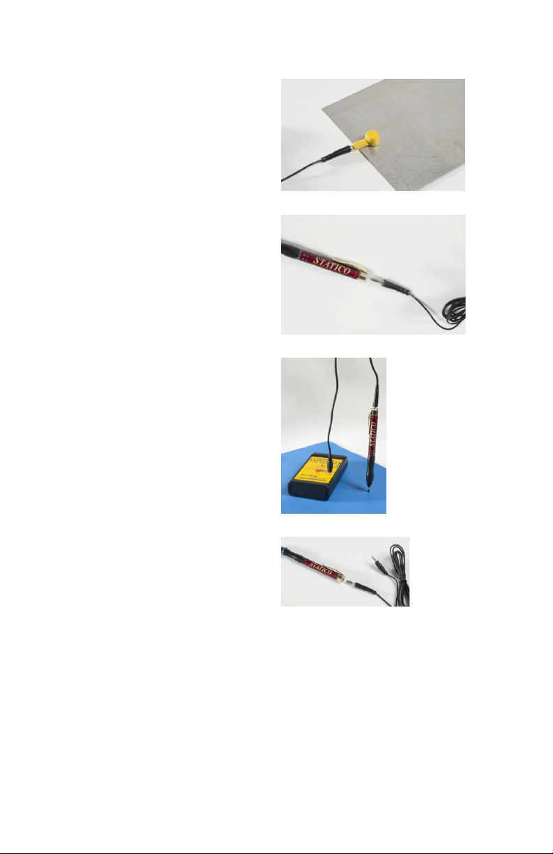
3. Connect the negative (-)
terminal to the test
platform.
4. Plug one end of the
provided with the
cord,
Kit, to the
SPP1
Single-Point
Pen
Probe.
5. Connect the other end
the coiled cord to
of
positive (+) terminal
the
your megohm
of
meter. If
comes with
end with a
plug, use that
and plug into the
your meter
cables that
banana
cable
Single-Point Pen
Probe.
6. Make sure that the conductive rubber boot is secure on the
ESD Systems - 3651 Walnut Ave, Chino CA 91710 • (909) 627-8178 • ESDSystems.com
TB-SPP February 2023
probe pin.
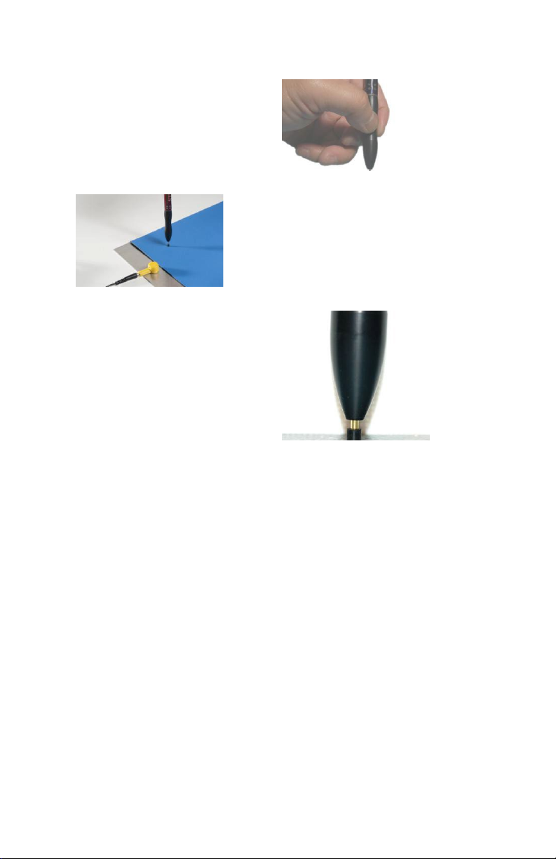
7. Hold the Pen Probe
vertically and place the
rubber tip on the
sample.
8. Apply pressure and
compress the pogo pin
until the probe body is
about 1/8” of an inch
from the rubber boot.
This would provide the
sufficient pressure for
correct contact force.
9.
Apply to test voltage from your meter to read the sample volume
resistance per ANSI/ESDA 11.12.
10.
Note: Volume resistance is shown as the reading from the meter
(in ohms) divided by the material thickness and shown in ohmcm or ohm-inch.
ESD Systems - 3651 Walnut Ave, Chino CA 91710 • (909) 627-8178 • ESDSystems.com
TB-SPP February 2023

MODEL SPP1: SINGLE-POINT PEN PROBE
Resistance to ground measurement for small piece parts
Introduction:
This test will measure resistance from various points on the top surface
of the piece part to the conductive platform that the bottom surface of the
sample is sitting on. The purpose of this test is to determine the ability of
the piece part to dissipate electrostatic charge from it surface to a fixture
or tool. The same possible current paths as the last section and all of
them will contribute to the charge dissipation characteristics of the
sample, as shown on the schematic below by Ben Baumgartner
(ESDiscovery 2000).
In this case, however, we want the edges to contribute to the readings.
For best result, the conductive platform should be larger than the
sample.
Procedures: Test procedure is the same as that for planar materials.
ESD Systems - 3651 Walnut Ave, Chino CA 91710 • (909) 627-8178 • ESDSystems.com
TB-SPP February 2023

MODEL SPP1: SINGLE-POINT PEN PROBE
Resistance to Ground Measurement for Equipment
Introduction:
Resistance to ground measurements for equipment determines if the
material installed in the production equipment has the ability to dissipate
electrostatic to the equipment ground. This test will measure resistance
from machine parts to the equipment chassis ground. It is recommended
to measure all machine parts within 12” ESD sensitive product handling
path per ANSI/ESDA 10.1, Automated Handlers.
For metal machine parts, an ohmmeter or the ohmmeter function of a
DVM can be used.
For coated or non-metallic machine parts, a megohm meter with applied
voltage of 10 volts or 100 volts as appropriate can be used.
Procedures:
1.
Connect the negative (-) terminal of your meter (ohmmeter or
megohmmeter) to the equipment chassis ground.
2.
Connect the positive (+)
terminal of your meter
(ohmmeter or Megohm meter)
to the Single-Point Pen Probe.
Note: When using the megohmmeter, the probe tip may be
energized up to 100 volts. Make sure that sensitive products are not
placed nearby the probe tip. Do not touch the probe tip with your
hand. Do not touch the probe tip to sensitive products.
3.
For metallic machine parts: Use an ohmmeter. Remove the
conductive rubber tip for the probe tip.
4.
Set the ohmmeter to auto range or to the lowest range of ohm
reading.
5.
Touch the bare (gold color) probe tip to various points on metallic
machine parts.
ESD Systems - 3651 Walnut Ave, Chino CA 91710 • (909) 627-8178 • ESDSystems.com
TB-SPP February 2023

6.
Apply pressure and compress the pogo pin until the probe body is
about 1/8” of an inch from the top of the pin contact. This would
provide the sufficient pressure for correct contact force.
7.
Record measurements.
Note: A properly grounded metallic machine part should have its
resistance to ground reading less than 1 ohm.
8.
For coated or non-metallic machine parts: Use a megohmmeter.
Make sure that the conductive rubber tip is installed.
9.
Set the applied voltage to 100 volts. Touch the probe tip to nonmetallic machine parts.
10.
Apply pressure and compress the pogo pin until the probe body is
about 1/8” of an inch from the rubber boot. This would provide the
sufficient pressure for correct contact force.
11.
Record measurements.
Note: A properly grounded static dissipative or ESD coated machine
part should have its resistance to ground reading less than 1 x 10
11
ohms.
ESD Systems - 3651 Walnut Ave, Chino CA 91710 • (909) 627-8178 • ESDSystems.com
TB-SPP February 2023

MODEL SPP2: TWO-POINT PENT PROBE
Point-to-Point Resistance Measurement for Materials
Introduction:
Point-to-point resistance measurements for planar material characterize
esthe ability of a planar (flat) sample to conduct electricity and
electrostatic charge from one point to another along the top-most layer of
the material. For thick samples with bulk conductivity, the resultant
reading can come from many paths of current flows, as shown below.
(Courtesy Ben Baumgartner, ESDicovery 2000)
This test is designed to check for hot spots on a sample of a finish
product where the NFPA probes (5lbs weights) are too large to detect or
to fit on the sample.
Procedures:
ESD Systems - 3651 Walnut Ave, Chino CA 91710 • (909) 627-8178 • ESDSystems.com
TB-SPP February 2023
1.
Place sample to be tested on an insulative platform such as
plastic or acrylic plate.

2. Install the BNC-toBanana adapter to the
end of the probe.
3. Connect banana jack
cables to the probe
adaptor.
3. Connect the other ends
of the cables to the
Mega-ohmmeter.
4.
Make sure that the conductive rubber boot is secure on
probe pins.
the
ESD Systems - 3651 Walnut Ave, Chino CA 91710 • (909) 627-8178 • ESDSystems.com
TB-SPP February 2023

5.
Hold the Pen Probe vertically
and place the
the sample.
rubber tips on
6.
Apply pressure and compress
the pogo pins until the probe
runs against the dead stop.
This would provide the
sufficient pressure for correct
contact force.
7.
Apply to test voltage from your meter to read the sample
volume resistance per ANSI/ESDA 11.13.
ESD Systems - 3651 Walnut Ave, Chino CA 91710 • (909) 627-8178 • ESDSystems.com
TB-SPP February 2023

MODEL S103PP: CONCENTRIC PEN PROBE
Ω
10
ANS. 10
Ω
/SQ.
Ω
10 Ω
10
V/I
SURFACE RESISTIVIT Y MEASUREMENT
(OHMS/SQ.)
Surface Resistance Measurement for Materials
Introduction:
Surface resistance measurements for planar material characterize the
resistance (and resistivity) of a planar (flat) sample.
(Courtesy Ben Baumgartner, ESDicovery 2000)
This test is
designed to
check for hot
spots on a
sample of a
finish product
where the
V/ I = 1.0Ω
x K
Ω
=1.0
x
NFPA probes
(5lbs weights)
are too large
to detect or to
fit on the
sample.
ESD Systems - 3651 Walnut Ave, Chino CA 91710 • (909) 627-8178 • ESDSystems.com
TB-SPP February 2023

Procedures:
1.
Place sample to be tested on an insulative platform such as
2.
Connect Coaxial adaptor
3.
Connect one end
4.
Connect the other ends
plastic or acrylic plate.
to the end of the probe.
banana jack cables to
the probe adapter.
5
ESD Systems - 3651 Walnut Ave, Chino CA 91710 • (909) 627-8178 • ESDSystems.com
TB-SPP February 2023
of the cables to the
Mega-ohmmeter.
Make sure that the conductive rubber boot is secure on the
probe pins.

6
Hold the Pen Probe vertically and place the rubber tips on the
sample.
7
Apply pressure and compress the pogo pins until the rubber ring
on the probe runs against the probe body. This would provide
the sufficient pressure for correct contact force.
8
Apply to test voltage from your meter to read the sample volume
resistance per ANSI/ESDA 11.13.
MAINTENANCE
Wipe conductive rubber probe tip(s) with a lint-free tissue moistened with
IPA periodically to remove contaminants.
Keep probe in a dry and cool place when not used.
Do not submerge probe in any liquid.
ESD Systems - 3651 Walnut Ave, Chino CA 91710 • (909) 627-8178 • ESDSystems.com
TB-SPP February 2023
 Loading...