

Page 1
TECHNICAL BULLETIN TB-2000
Installation and
Maintenance of ESD Mats
Introduction
The purpose of an ESD worksurface is to aid in the prevention
of damage to ESD sensitive components and assemblies from
electrostatic discharge. An ESD worksurface provides protection in
the following two ways:
1. Providing an antistatic worksurface area that will limit static
electricity generation.
2. Removing the charge from a conductive object placed on the
worksurface.
A dissipative worksurface having a surface resistance of at least 1
6
x 10
, but less than 1 x 10⁹ ohms is recommended by worksurface
standard ANSI/ESD S4.1. Dissipative materials minimize the
generation of static charges, and will dissipate a charge slow
enough so that a spark will not occur. Dissipative materials are
usually the preferred choice for bench top worksurfaces.
Conductive materials are the quickest to remove a charge,
but they can also cause damage by discharging too rapidly.
Conductive materials are usually used as floor mats, which is
defined by ANSI/ESD S7.1 as less than 1 x 10
General Grounding Guidelines
1. ANSI/ESD S20.20 requires that all conductors in an ESD
protected area, including personnel, must be grounded.
2. The ESD ground must be tied directly to and at the same
potential as the building or “green wire” equipment ground.
3. Per ANSI/ESD S20.20, the ESD control program can in no
way replace or supercede any requirements for personnel
safety. Ground fault circuit interrupters (GFCI) and other safety
protection should be considered wherever personnel might
come into contact with electrical sources.
4. All electrical outlets should be verified for proper wiring
configuration, resistance or impedance and GFCI function when
the mat is installed and periodically thereafter.
Common Point Grounds
A common point ground is defined by the grounding standard
ANSI/ESD S6.1, as:
1. A grounded device where two or more conductors are bonded.
2. A system or method for connecting two or more grounding
conductors to the same electrical potential.
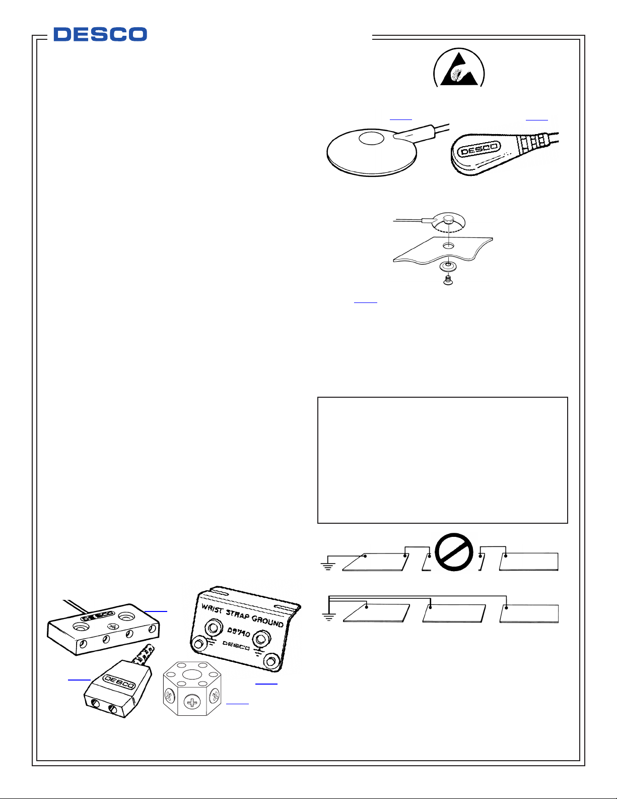
Examples of common point grounds with ground cords are
illustrated below.
6
ohms.
Made in the
United States of America
09814
Figure 2. Other ground cords.
Figure 3. 09814 with screw allows ground cord to be bolted to
mat to keep cord from disconnecting.
Common point grounds are designed to provide ground for
worksurface mats, wrist straps, and other items.
NOTE: DO NOT DAISY CHAIN. Because of the high resistances
inherent to many types of protective surfaces, daisy chaining of
these materials can severely limit their ability to properly dissipate
and protect against static charges.
09817
COMMON POINT GROUND
Per ANSI/ESD S6.1, Grounding section 4.1.1 “Every element to be
grounded at an ESD protected station shall be connected to the
same common point ground.”
ESD Handbook ESD TR20.20 section 5.1.3 Basic Grounding
Requirements “The first step in ensuring that everything in an
EPA is at the same electrical potential is to ground all conductive
components of the work area (worksurfaces, people, equipment,
etc.) to the same electrical ground point. This point is called the
common point ground. The next step in completing the ground
circuit is to connect the common point ground to the equipment
ground (third wire, green).”
WRONG!
09835
RIGHT
Figure 4. ESD mats should never be grounded in series, that is
09825
Figure 1. Typical common point grounds.
TB-2000 February 2015 Page 1 of 4
Find Quality Products Online at: [email protected]
www.GlobalTestSupply.com
09740
09837
daisy chained.
© 2015 DESCO INDUSTRIES INC.
Employee Owned
Page 2
Grounding Methods
Method 1 (Grounding via ground cords)
1. Desco recommends using a common point ground cord when
grounding via ground cords. Most common point ground cords
will ground your ESD worksurface and provide banana jack
ground points for two wrist straps.
2. A common point ground should be installed at each workstation
and should be connected directly to a verified “green wire”
equipment ground. Only one groundable point should exist on a
worksurface.
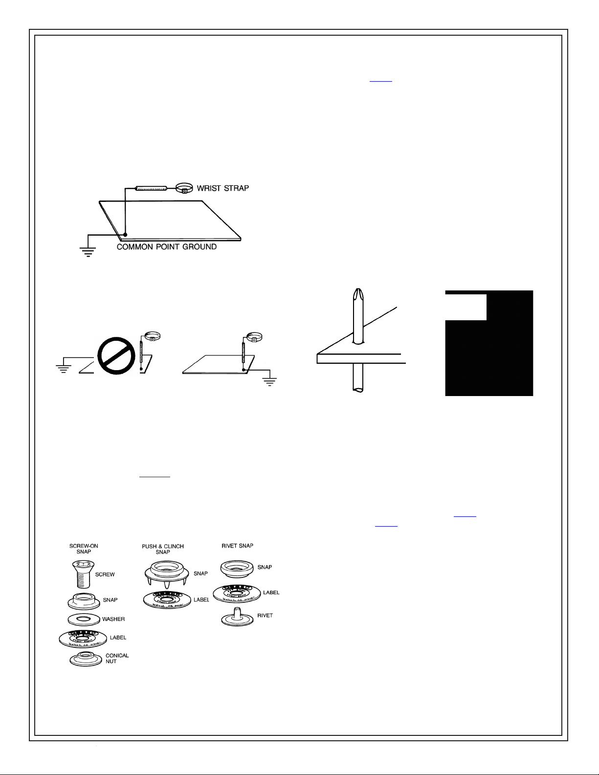
Figure 5. Common point ground for each workstation.
2. Desco has three types of 10mm (0.395") field installable mat
grounding snaps. The first type is a screw-on snap kit Desco
item number 09864 Universal Snap Kit.
A. Determine the position of the grounding snap (one only per
mat) and type of fastener you will be installing (socket or
stud). Take precautions not to cut your hand, and punch a
hole through the material with a small Phillips screwdriver or
awl.
B. Remove the release paper from the circular common point
ground label and affix it so that it aligns with the hole on the
material.
C. Select one of the screws as follows:
Material less than 0.100" thick - short screw
Material greater than 0.100" thick - long screw
D. Insert the screw through the top on the snap stud or socket,
the washer, the label and the material. Affix the assembly
with the conical nut supplied with the kit and tighten down
the screw using a Phillips screwdriver.
E. Remaining will be either a 10mm stud or socket, and either
a long or short screw to be discarded or saved for another
application.
3. Wrist straps should never be grounded through a worksurface,
as the added resistance of the worksurface material will
prevent the wrist strap from operating properly.
WRONG! RIGHT!
Figure 6. Proper grounding of wrist straps.
4. Per ANSI/ESD S1.1, a current limiting resistor in the wrist strap
ground cord is recommended. If other than a one megohm
resistor, special marking in red is required.
For additional information on grounding we recommend
Desco Technical Bulletin TB-2007.
Groundable Point Installation
1. Before installing a groundable point on your mat you must first
determine whether you will need a snap socket or stud, the
type of snap hardware and the location.
ASSEMBLE
SCREW, STUD,
WASHER, LABEL
AND CONICAL NUT
USE A PHILLIPS
SCREWDRIVER OR
AWL TO PUNCH
A HOLE IN THE
MATERIAL
AS SHOWN
Figure 8. Installing Universal Snap Kit on mat.
3. The second type of mat grounding snap is the push and clinch
snap. This snap is designed for use with any type of soft mat
material: dissipative, conductive or multi-layered. It is
recommended for use with three-layered material, because it
provides excellent contact with the internal con ductive scrim
layer. It is recommended that before inserting this snap, the mat
be punctured with a sharp tool where the snap will be placed.
Take precautions not to cut your hand. Push and Clinch snaps
are available as a snap stud as item 09861 and as a snap
socket as item 09863.
A. Remove the release paper from the circular label and
affix it onto the mat material in the desired location.
B. Center the prongs on the snap assembly with the label. Apply
pressure to the snap until the prongs come through the back
of the mat, then clinch over prongs to secure snap as shown
in Figure 9.
Figure 7. Three kinds of snaps.
TB-2000 Page 2 of 4
Find Quality Products Online at: [email protected]
www.GlobalTestSupply.com
© 2015 DESCO INDUSTRIES INC.
Employee Owned
Page 3
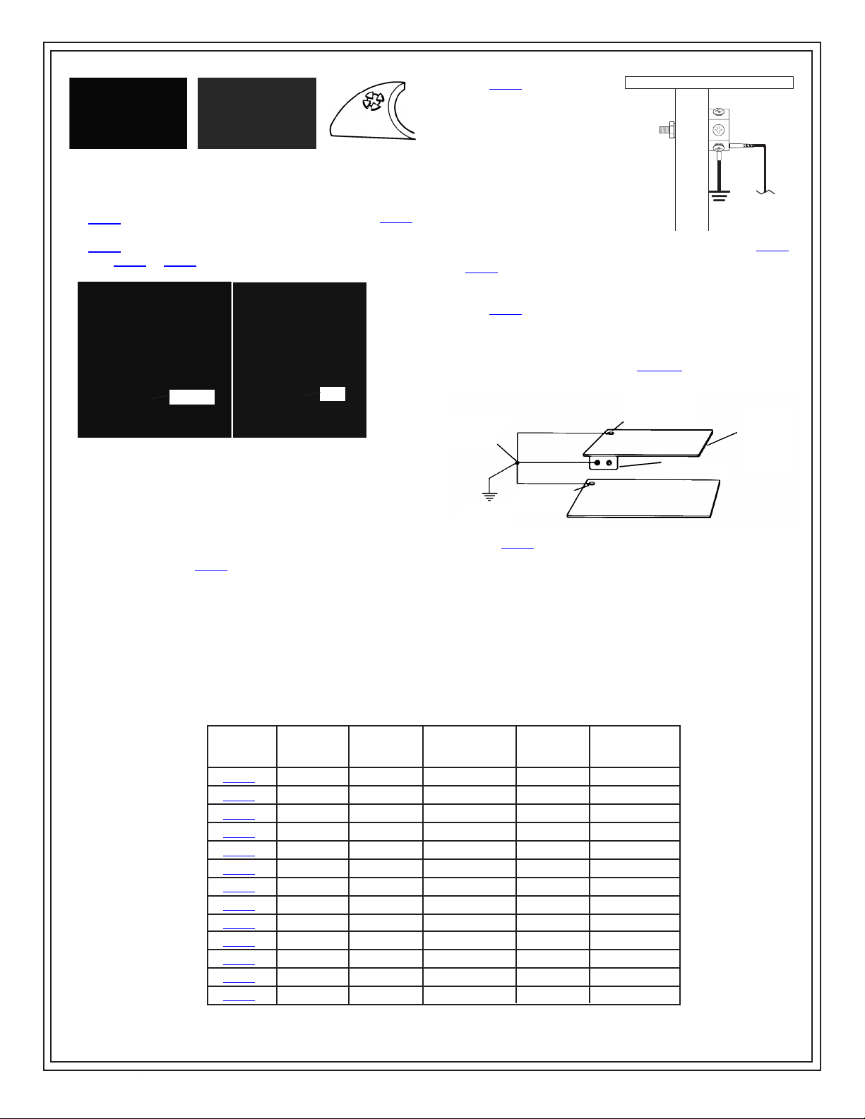
Figure 9. Installing push and clinch mat grounding snap.
4. The third type is the rivet style mat grounding snap. This type
of snap assembly is installed using a rivetting hand tool, item
09867. Male snap studs and rivets are available as item 09856
and female snap sockets and rivets are available as item
09857. Groundable point labels are not included with either the
item 09856 or 09857 snap kits.
3. The 09837 Multi Ground
Hub is designed for
use as either a multiple
grounding block or as a
common point ground.
The Multi Ground
Hub incorporates six
standard banana jacks,
and six terminations for
ring terminals (10-32
screw in threaded
holes). Note: Also
available as Desco item
19219 Ground Hub
Figure 11. Mounting the
09837 to a table leg.
Monitor
4. The 09740 dual bench mount allows the grounding of
two operators at one common point. The 09740 mounts
easily under the front edge of a workstation. For
detailed information on
this common point grounding
device ask for Technical Bulletin TB-2003.
Socket
Stud
Figure 10. Installation using a rivetting hand tool.
Selection of Common Point and
Floor Mat Grounding Systems
1. Determine the type of common point grounding system you will
use: barrier strip, bus bar, grounding block, or common point
ground cord. Desco recommends the use of common point
ground cords or our 09740 dual bench mount.
2. If you determine that you will use ground cords, you must now
determine the type of ground cord you will use for your
workstation grounds. ANSI/ESD S6.1 recommends that a nonresistor ground cord be used to ground worksurfaces and floor
mats. However, cord may have a 1 megohm resistor for non
ESD puropses. Selection of the ground cord is determined by
user needs and specifications.
Desco Ground Cord Item Numbers
Designed
for Floor
Mat Use
X
X
X
X
Model #
09814
09813
09817
09818
09820
09821
09825
09826
09835
09836
09837
09740
09741
1 Megohm
Resistor
X
X
X
X
X
Common
Ground
Point
Floor Mat
Equipment
Ground
Ground
Snap
Figure 12. 09740 dual bench mount.
Designed for
Worksurface
Use
X
X
X
X
X
X
X
X
X
Wire
Length
15'
15'
10'
10'
10'
10'
15'
15'
10'
10'
6'
10'
10'
Worksurface Mat
Snap Ground
Wrist Strap
Ground
Banana
Jacks
0
0
0
0
2
2
2
2
4
4
6
2
2
Do Not Hook
A Second
Surface or
Device Here
TB-2000 Page 3 of 4
Find Quality Products Online at: [email protected]
www.GlobalTestSupply.com
© 2015 DESCO INDUSTRIES INC.
Employee Owned
Page 4
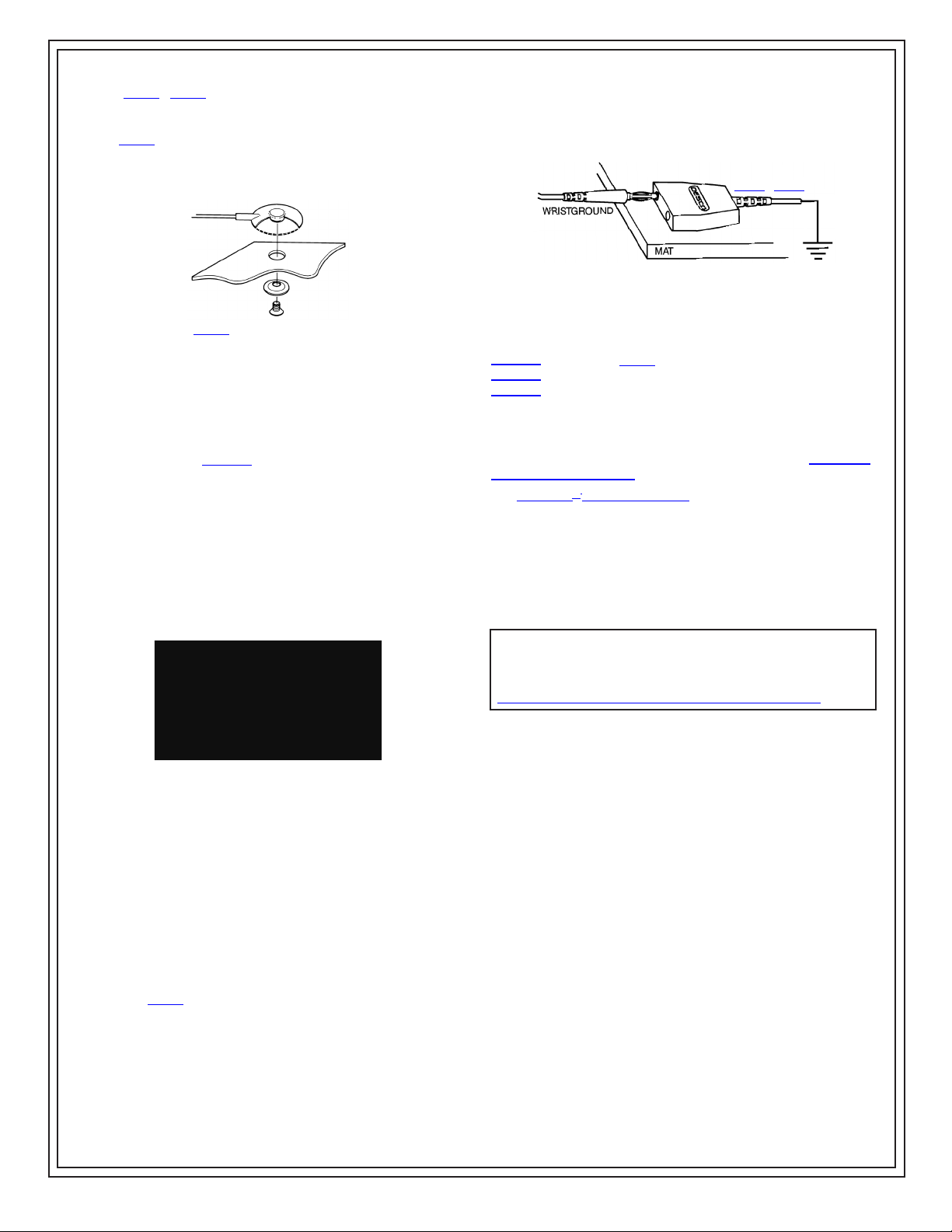
6. The 09813 / 09814 mat ground cord may be either attached to
a mat by snapping onto a 10mm socket, or by bolting it to the
mat with the hardware supplied with the cord. When bolting
the 09814 to the mat use a 3/8" diameter hole punch to create
the hole for mounting. This will allow cord to sit flush on the
mat. Note: For both applications, remove screw from floor mat
ground before attaching to mat.
Figure 13. Installing 09814 to mat using supplied hardware.
Mat Installation - General Information
1. For best results, allow the mats to lay flat for about four hours
at room temperature before installing. This will give the material
time to flatten out from being rolled for shipment.
2. Test grounds for proper resistance to ground. See Desco
Technical Bulletin TB-2007 for a complete discussion of
grounds.
3. Lay the mat in position and snap the ground cord to it. Bring the
other end of the ground cord to the common ground point and
attach it using the ring terminal. A suggested ground point is
the center screw of a standard AC electrical outlet. Testing is
recommended to ensure that the screw is properly grounded.
Tie the ground wire to the bench to keep it out of the way and
neat. You may cut and strip the ground wire to a shorter length
and attach it with the extra ring terminal included with each
Desco ground cord.
RING
“GREEN WIRE”
UTILITY
GROUND
POINTS
TERMINAL
CAN BE
ATTACHED
HERE
7. If you are using a mat kit that includes the wrist strap, install
the wrist strap directly to the common point mat ground cord
banana jack. Again, test the resistance from the backplate of
the wrist strap to the common ground point. It should read 1
Megohm ± 20 percent.
09825 / 09826
Figure 15. Adding the wriststrap.
BE SURE YOU TEST ALL GROUNDS AND THE WRIST STRAP
FREQUENTLY.
The following bulletins are available from Desco:
TB-2004 Operation of 19350 Wrist Strap Tester
TB-2005 Wrist Straps, Grounding, Testing, Maintenance
TB-2007 Safe Grounding of Static Controlled Workstations
Maintenance and Cleaning
For optimum performance, periodic cleaning is required following
manufacturer’s recommendations. Desco recommends Reztore™
Surface and Mat Cleaner for workstation mats and other surfaces
and Statguard® Floor Mat Cleaner for floor mats.
Note: Desco’s Reztore™ Surface and Statguard® Floor Mat
Cleaners contain no silicone or harsh solvents. Cleaners with
silicone leave an insulative residue on surfaces and solvents such
as 2-Butoxyethanol or Ethanolamine used in cleaners can dry out
the material; both can prevent conductive or dissipative mats from
functioning properly.
Limited Warranty, Warranty Exclusions, Limit of Liability
and RMA Request Instructions
Figure 14. Hooking up ground cords.
4. If your installation includes a floor mat, you should duplicate
step 2 and attach the floor mat ground to the same point as the
worksurface ground wire.
5. Measure the resistance from the ground snap on the mat to the
common ground point. It should read 1 megohm ± 20 percent if
you are using a ground cord with a resistor, and less than 1
ohm if you are using a non-resistor ground cord.
6. Using a surface resistance tester per ESD TR53, test the
resistance to ground from the center of the mat surface.
Required equipment: a megohmmeter with 100 volt open test
circuit voltage and two five pound electrodes per ASTM-150.
Desco sells this as the Digital Surface Resistance Meter
Kit, item 19787.
TB-2000 Page 4 of 4
Find Quality Products Online at: [email protected]
www.GlobalTestSupply.com
© 2015 DESCO INDUSTRIES INC.
Employee Owned
 Loading...