

Desa S36, S36RH, S36H, S36R, VS361 Installation Instructions Manual
...
A
N
I
RESIDENTIAL AND OUTDOOR WOODBURNING FIREPLACE
S36 36” textured white refractory brick
S36H
36” textured white herringbone refractory brick
S36R 36” textured red refractory brick
S36RH 36” textured red herringbone refractory brick
VS36(1) 36” smooth white refractory brick
VS36H(1) 36” smooth white herringbone refractory brick
INSTALLATION INSTRUCTIONS
This book is valuable. In addition to instructing you on
how to install and maintain your appliance, it also
contains information that will enable you to obtain
replacement parts or accessory items when needed.
Keep it with your other important papers.
SAVE THIS BOOK
WARNING: Always leave glass doors fully opened or fully closed when operating this fireplace.
This fireplace is approved for use as a wood burning fireplace or for use
with a vented gas log approved to ANS Z21.60, Z21.84 or RGA 2-72
standards or
Z21.11.2 standard. A DESA hood must be installed when using a ventfree gas log heater (see Accessories, p. 12).
for use with a vent-free gas log heater approved to ANS
LL DIMENSIONS IN THIS MANUAL ARE I
NCHES UNLESS OTHERWISE SPECIFIED
DESA INTERNATIONAL
2701 INDUSTRIAL DRIVE P/N 111026-01
P.O. BOX 90024 REV A
BOWLING GREEN, KY 42101-9004 11/02
www.desatech.com
OMNI-Test Laboratories, Inc.

CONTENTS
1. INTRODUCTION ------------------------------------------------------------- PG. 2
2. SELECTING LOCATION ------------------------------------------------------------- PG. 2
3. MINIMUM CLEARANCES ------------------------------------------------------------- PG. 2
4. FRAMING AND INSTALLING ------------------------------------------------------------- PG. 3
5. HEARTH EXTENTION ------------------------------------------------------------- PG. 3
6. OUTSIDE AIR KIT INSTALLATION ------------------------------------------------------------- PG. 3
7. CHIMNEY PIPE AND OFFSET INSTALLATION ------------------------------------------------------------- PG. 4-5
8. FIRESTOP SPACERS ------------------------------------------------------------- PG. 5
9. FLASHING AND TERMINATION ------------------------------------------------------------- PG. 6-7
10. FINISHING YOUR FIREPLACE ------------------------------------------------------------- PG. 7
11. MANTELS ------------------------------------------------------------- PG. 8
12. GLASS DOORS ------------------------------------------------------------- PG. 8
13. GAS LINE INSTALLATIONS ------------------------------------------------------------- PG. 9
14. DAMPER OPERATION ------------------------------------------------------------- PG. 10
15. TECHNICAL SERVICE ------------------------------------------------------------- PG. 10
16. ILLUSTRATED PARTS ------------------------------------------------------------- PG.11-11a
17. REPLACEMENT AND TECHNICAL PARTS ------------------------------------------------------------- PG.12
- 1 - For more information, visit www.desatech.com
r
d
n
p
r
d
t
h
h
b
r
• Do not store or use gasoline or any other flammable
vapors or liquids in the vicinity of this or any othe
appliance.
• Due to high temperatures, the appliance should be
located out of traffic and away from furniture an
draperies.
• Do not place clothing or other flammable materials o
or near the appliance.
• NEVER leave children unattended when a fire is
burning in the fireplace.
FOR YOUR SAFETY
WARNING: Improper installation, adjustment,
alteration, service or maintenance can cause injury,
roperty damage, or loss of life. Refer to this manual fo
assistance or additional information. Consult a qualifie
installer or local distributor.
CHECK LOCAL CODES BEFORE
INSTALLING THIS FIREPLACE.
INTRODUCTION
BEFORE BEGINNING THE INSTALLATION OF THE
FIREPLACE, READ THESE INSTRUCTIONS THROUGH,
COMPLETELY.
♦ This DESA fireplace and its components are safe
when installed according to this installation manual.
Unless you use DESA components, which has been
designed and tested for the fireplace system, you may
cause a fire hazard.
♦ The DESA warranty will be voided by and DESA
disclaims any responsibility for the following actions:
a) Modification of the fireplace, components, doors,
air inlet system and damper control.
b) Use of any component part not manufactured or
approved by DESA in combination with a DESA
fireplace system.
PROPER INSTALLATION is the most important step in
ensuring safe and continuous operation of the fireplace.
Consult the local building codes as to the particular
requirements concerned with the installation of all factory
built fireplaces
WARNING: Do not install a fireplace insert in this
box unless the manufacturers instructions with the inser
specifically state this fireplace has been tested for use
with the insert.
USE SOLID WOOD OR PROCESSED SOLID FUEL
FIRELOGS ONLY.
WARNING: When processed wood fuel fire logs
are used, do not poke or stir the logs while they are
urning. Use only fire logs that have been evaluated fo
the application in fireplace and refer to fire log warnings
and caution markings on packaging prior to use.
This fireplace is not intended to be used as a substitute for
a furnace to heat an entire home. Use for supplemental
heat only.
This wood-burning fireplace complies with UL 127CAN/ULS-S610-M87 standard as a FACTORY BUILT
FIREPLACE.
FOR CANADA: The authority having jurisdiction (suc
as the municipal building department, fire department,
etc.) should be contacted before installation to determine
the need to obtain a permit.
SELECTING LOCATION
To determine the safest and most efficient location for the
fireplace, you must take into consideration the following
guidelines:
1.) The location must allow for proper clearances (see
figures 1 & 2).
2.) Consider a location were the fireplace would not be
affected by drafts, air conditioning ducts, windows or
doors.
3.) A location that avoids the cutting of joists or roof
rafters will make installation easier.
4.) An outside air kit is available with this fireplace. For
more details refer to section on outside air kit
installation on page 3.
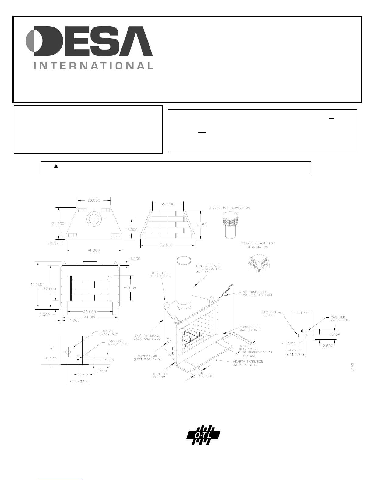
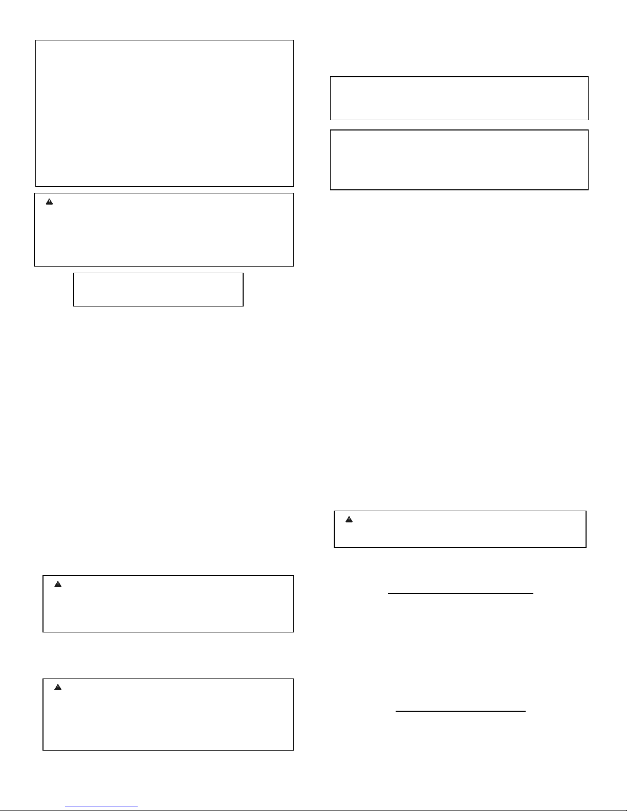
MINIMUM CLEARANCES TO COMBUSTIBLES
• Back and side of fireplace -------------- ¾” minimum
Note: The ¾” clearance is not required at the nailing flanges
• Floor* ------------------------------------- 0” minimum
*See step 2 of “Installing the Fireplace” on page 3
• Perpendicular Wall to Opening of unit - 12” minimum
• Top Spacers ------------------------------ 0” minimum
• Mantel Clearances ---------------------- see page 8
“Mantels”
• Chimney Outer Pipe Surfaces --------- 1” minimum
WARNING: Do not pack required air spaces wit
insulation or other materials.
MINIMUM / MAXIMUM CHIMNEY HEIGHT
RESIDENTIAL INSTALLATION
The minimum height of the chimney, measured from the base
of the fireplace to the flue gas outlet of the termination, is 14.5
feet for straight flue or a flue with one elbow set. The
maximum distance between elbows is 6 feet. For systems
with two elbow sets, the minimum height is 22 feet. The
maximum height of any system is 50 feet. This measurement
includes the fireplace, chimney sections and the height of the
termination assembly at the level of the flue gas outlet (see
page 7, figure 15).
OUTDOOR INSTALLATION
The minimum height of the chimney, measured from the base
of the fireplace to the flue gas outlet of the termination, is 7.5
feet (minimum 4 feet of chimney pipe section required for
outdoor installation).
-2 - For more information, visit www.desatech.com
FRAMING AND INSTALLING THE FIREPLACE
y
g
h
p
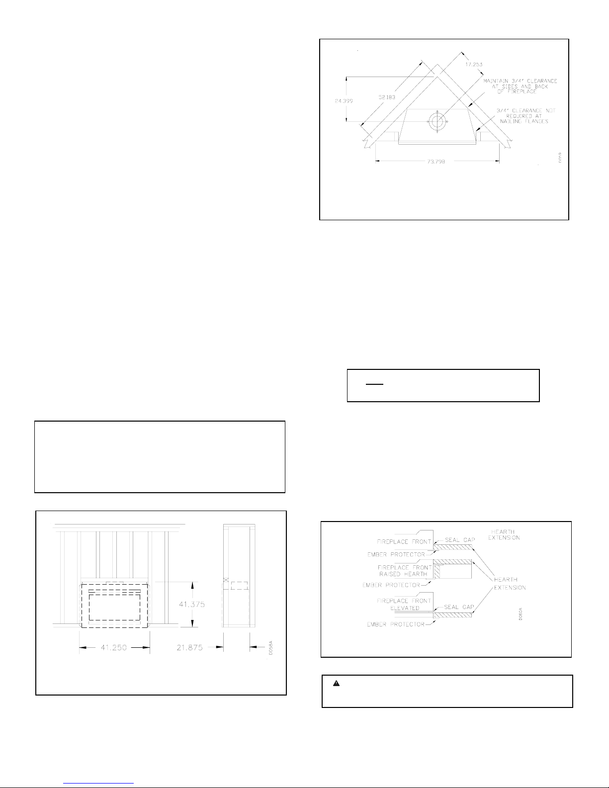
STEP 1: Frame the opening for the fireplace using the
dimensions shown in figures 1 & 2.
STEP 2: If the fireplace is to be installed directly on carpeting,
tile (other than ceramic), or any combustible material other
than wood flooring, the fireplace must be installed upon a
metal or wood panel extending the full width and depth of the
fireplace.
STEP 3: Set the fireplace directly in front of this opening and
slide the unit back until the nailing flanges touch the side
framing.
STEP 4: Check the level of the fireplace and shim with sheet
metal if necessary. Make sure the unit is balanced on each
side.
STEP 5: Before securing fireplace to prepared framing, the
ember protector (provided), must be placed between the hearth
extension (not supplied), and under the bottom front edge of
the fireplace to protect against glowing embers falling
through. If the fireplace is to be installed on a raised platform,
a Z-type ember protector (not supplied) must be fabricated to
fit your required platform height. The ember protector should
extend under the fireplace a minimum of 1 - 1/2”. The ember
protector should be made of galvanized sheet metal (28-gage
minimum).
STEP 6: Using screws or nails, secure the fireplace to the
framing through flanges located on the sides of the fireplace.
NOTE: For outdoor installations, the fireplace enclosure
must allow for adequate drainage and fresh air ventilation.
It is recommended that a sealed, corrosion resistant catc
an with provision for drainage, be installed under the
fireplace within the fireplace enclosure.
Figure 1 CORNER INSTALLATION
Figure 2 CORNER INSTALLATION
HEARTH EXTENSION
A hearth extension projecting a minimum of 16” in front of
and a minimum of 8” beyond each side of the fireplace
opening is required to protect combustible floor construction
in front of the fireplace. Fabricate a hearth extension using a
material which meets the following specifications: a layer of
non-combustible, inorganic material having a thermal
conductivity of K = 0.84 BTU IN/FT. HR. F (or less) at 1”
thick. For example, if the material selected has a K factor of
0.25, such as glass fiber, the following formula would apply:
0.25 x 1.0” = 0.30 thickness required
0.84
Thermal conductivity “K” of materials can be obtained from
the manufacturer or supplier of the non-combustible material.
If the hearth extension is to be covered, use non-combustible
material such as tile, slate, brick, concrete, metal, glass,
marble, stone etc. Provide a means to prevent the hearth
extension from shifting and seal gap between the fireplace
frame and hearth extension with a non-combustible material
(see figure 3).
Fi
ure 3 HEARTH EXTENSION
WARNING: Hearth extension is to be installed onl
as illustrated.
- 3 - For more information, visit www.desatech.com
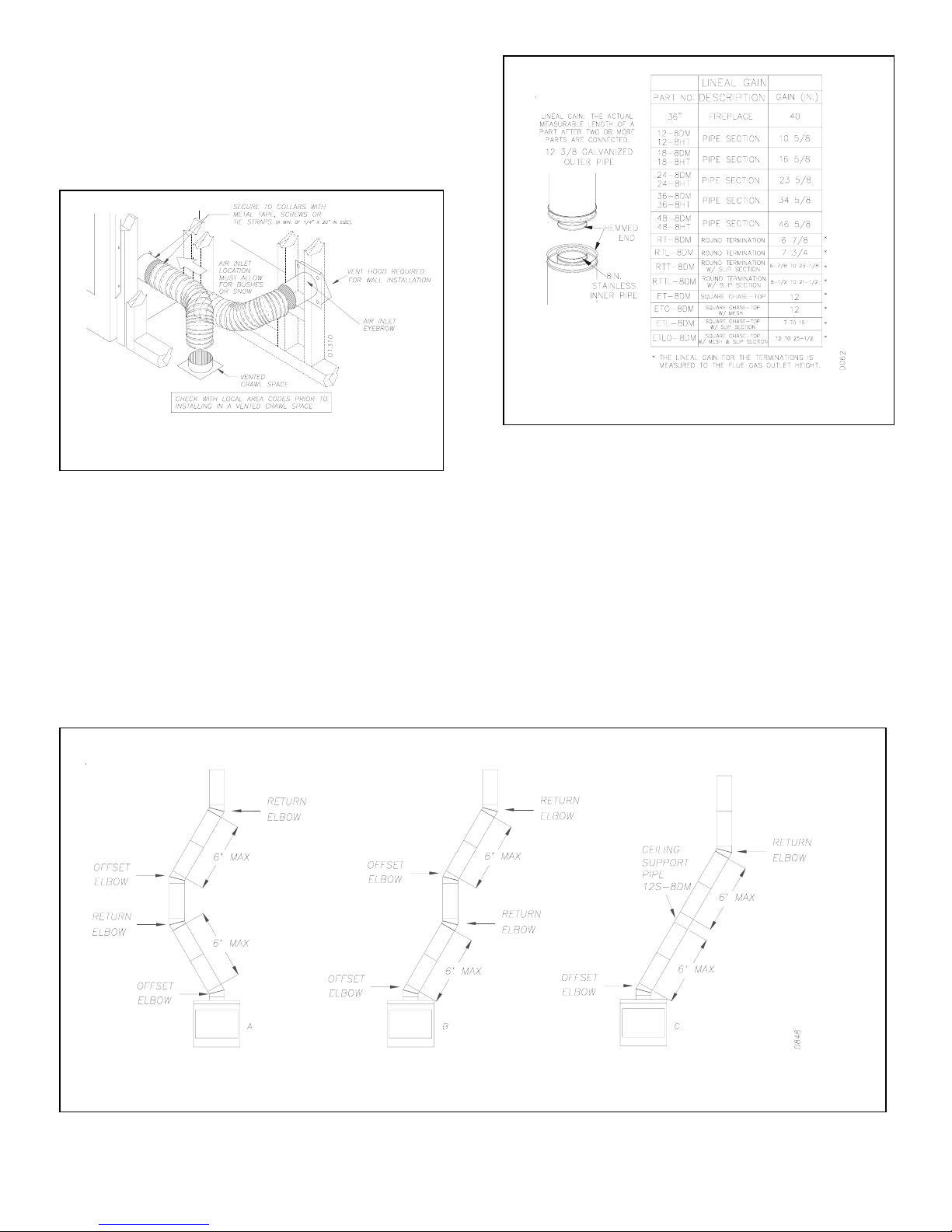
OPTIONAL OUTSIDE AIR KIT (MODEL AK4 / AK4F)
The installation of an outside air kit should be performed
during the rough framing of the fireplace due to the nature of
its location. Outside combustion air is accessed through a
vented crawl space (AK4F) or through a sidewall (AK4). See
page 10, figure 21 for instructions on how to operate the air
kit.
Figure 4 OUTSIDE AIR KIT
CHIMNEY PIPE
The DESA chimney system consists of 12, 18, 24, 36 and 48
inch, snap-lock double-wall pipe segments, planned for
maximum adaptability to individual site requirements. Actual
lengths gained after fitting overlaps must be taken into
consideration (lineal gain) and are given in the lineal gain
chart (see figure 5).
ASSEMBLY AND INSTALLATION OF THE DOUBLE
WALL CHIMNEY SYSTEM
Each double wall chimney section is consist of a galvanized
outer pipe, a stainless steel inner flue pipe and a wire spacer.
The pipe sections must be assembled independently as the
chimney is installed.
Figure 6 *TYPICAL OFFSET INSTALLATION
*For systems with two elbow sets, the minimum height is 22 feet. The maximum height for any system is 50 feet.
Figure 5 LINEAL GAIN
For Canada, use chimney parts designated “HT”
When connecting chimney directly to the fireplace, the inner
flue pipe section must be installed first with the lanced side
up. The outer pipe section can then be installed over the flue
pipe section with the hemmed end up.
Press down on each pipe section until the lances securely
engage the hem on the fireplace starter. The wire will assure
the proper spacing between the inner and outer pipe sections.
Continue to assemble chimney sections as outlined above,
making sure that both the inner and outer pipe sections are
locked together. When installing double wall “snap lock”
chimney together, it is important to assure the joint between
the chimney sections is locked. Check by pulling chimney
upward after locking. The chimney will not come apart if
properly locked. It is not necessary to add screws to keep the
chimney together (exception – see page 5 figure 8).
- 4 - For more information, visit www.desatech.com
 Loading...