

Desa VP10A,VN10TA, VN600BA, VP600BA, VN1000BTA, VP1000BTA Owner's Operation And Installation Manual
...
VENT-FREE GAS HEATER
OWNER’S OPERATION AND INSTALLATION MANUAL
VN600BA, VP600BA, VN1000BTA, VP1000BTA
VN10A, VP10A. VN10TA, VP10TA, VN6D, VP5D
WARNING: If the information in this manual is not followed exactly, a fire or explosion may result causing
property damage, personal injury, or loss of life.
— Do not store or use gasoline or other flammable
vapors and liquids in the vicinity of this or any other
appliance.
— WHAT TO DO IF YOU SMELL GAS
• Do not try to light any appliance.
• Do not touch any electrical switch; do not use any
phone in your building.
• Immediately call your gas supplier from a neighbor’s
phone. Follow the gas supplier’s instructions.
• If you cannot reach your gas supplier, call the fire
department.
— Installation and service must be performed by a quali-
fied installer, service agency, or the gas supplier.
Save this manual for future reference.
For more information, visit www.desatech.com
www.desatech.com
110720-01G
2
WARNING: Improper installation, adjustment, alteration, service, or maintenance can cause injury or property damage. Refer to this manual for correct installation
and operational procedures. For assistance or additional information consult a qualified installer, service
agency, or the gas supplier.
WARNING: This is an unvented gas-fired heater. It uses
air (oxygen) from the room in which it is installed. Provisions for adequate combustion and ventilation air must
be provided. Refer to Air for Combustion and Ventilation
section on page 5 of this manual.
This appliance may be installed in an aftermarket,* permanently located, manufactured (mobile) home, where
not prohibited by local codes.
This appliance is only for use with the type of gas indi
cated on the rating plate. This appliance is not convertible for use with other gases.
* Aftermarket: Completion of sale, not for purpose of resale, from the manufacturer
TABLE OF CONTENTS
Safety Information ............................................... 3
Unpacking ........................................................... 4
Product Identification ........................................... 4
Product Features ................................................. 4
Local Codes ........................................................ 5
Air for Ventilation and Combustion ......................
5
Installation ........................................................... 7
Operating Heater ............................................... 13
Inspecting Burner .............................................. 18
Cleaning and Maintenance ................................ 19
Troubleshooting .................................................
20
Illustrated Parts Breakdown and Parts List ....... 24
Specifications .................................................... 34
Replacement Parts ............................................ 34
Service Hints ..................................................... 34
Technical Service ..............................................
35
Service Publications .......................................... 35
Accessories ....................................................... 35
Parts Centrals .................................................... 35
Warranty I
nformation ...........................Back Cover
www.desatech.com
110720-01G 3
SAFETY INFORMATION
IMPORTANT: Read this owner’s
manual carefully and completely
before trying to assemble, op
erate, or service this heater.
Improper use of this heater can
cause serious injury or death
from burns, fire, explosion,
electrical shock, and carbon
monoxide poisoning.
DANGER: Carbon monoxide
poisoning may lead to death!
Carbon Monoxide Poisoning: Early signs of carbon
monoxide poisoning resemble the flu, with head
aches, dizziness, or nausea. If you have these signs,
the heater may not be working properly. Get fresh
air at once! Have heater serviced. Some people
are more affected by carbon monoxide than others.
These include pregnant women, persons with heart
or lung disease or anemia, those under the influence
of alcohol, and those at high altitudes.
Natu ral an d Prop ane/LP Gas: Natural and
propane/LP gases are fuel gases. Fuel gases are
odorless. An odor-making agent is added to fuel
gases. The odor helps you detect a fuel gas leak.
However, the odor added to fuel gas can fade. Fuel
gas may be present even though no odor exists.
Make certain you read and understand all warn
ings. Keep this manual for reference. It is your
guide to safe and proper operation of this heater.
WARNING: Any change to
this heater or its controls can
be dangerous.
WARNING: Do not use a
blower insert, heat exchanger
insert or other accessory not approved for use with this heater.
Due to high temperatures, the
appliance should be located out
of traffic and away from furniture
and draperies.
Do not place clothing or other
flammable material on or near
the appliance. Never place any
objects on the heater.
Surface of heater becomes very
hot when running heater. Keep
children and adults away from
hot surface to avoid burns or
clothing ignition. Heater will
remain hot for a time after shut
down. Allow surface to cool
before touching.
Carefully supervise young children when they are in the same
room with heater.
Make sure grill guard is in place
before running heater.
Keep the appliance area clear
and free from combustible materials, gasoline, and other flammable vapors and liquids.
1. This appliance is only for use with the type of
gas indicated on the rating plate. This appliance
is not convertible for use with other gases.
2. Do not place propane/LP supply tank(s) in
side any structure. Locate propane/LP supply
tank(s) outdoors.
3. Do not install 10,000 Btu units in a bath
room
4. If you smell gas
• Shut off gas supply
• Do not try to light any appliance
• Do not touch any electrical switch; do not
use any phone in your building
• Immediately call your gas supplier from a
neighborʼs phone. Follow the gas supplierʼs
instructions
• If you cannot reach your gas supplier, call
the fire department
5. This heater needs fresh, outside air ventilation
to run properly. This heater has an Oxygen
Depletion Sensing (ODS) safety shutoff
system. The ODS shuts down the heater if
not enough fresh air is available. See Air for
Combustion and Ventilation,
page 5.
www.desatech.com
110720-01G
4
6. Always run heater with control knob at LOW or
HIGH locked positions (VP10A) or ON position
(VP5D). Never set control knob between locked
positions. Poor combustion may result.
7. Keep all air openings in the front and bottom
of heater clear and free of debris. This will
insure enough air for proper combustion.
8. If heater shuts off, do not relight until you
provide fresh, outside air. If heater keeps
shutting off, have it serviced.
9. Do not run heater
• where flammable liquids or vapors are used
or stored
• under dusty conditions
10. Before using furniture polish, wax, carpet
cleaner, or similar products, turn heater off.
If heated, the vapors from these products may
create a white powder residue within burner
box or on adjacent walls or furniture.
11. Do not use heater if any part has been under
water. Immediately call a qualified service
technician to inspect the room heater and to
replace any part of the control system and any
gas control which has been under water.
12. Turn off heater and let cool before servicing.
Only a qualified service person should service
and repair heater.
13. Operating heater above elevations of 4,500
feet could cause pilot outage.
14. To prevent performance problems, do not
use propane/LP fuel tank of less than 100
lbs. capacity.
15. Provide adequate clearances around air
openings.
UNPACKING
1. Remove heater from carton.
2. Remove all protective packaging applied to
heater for shipment.
3. Check heater for any shipping damage. If
heater is damaged, promptly inform dealer
where you bought heater.
SAFETY INFORMATION
Continued
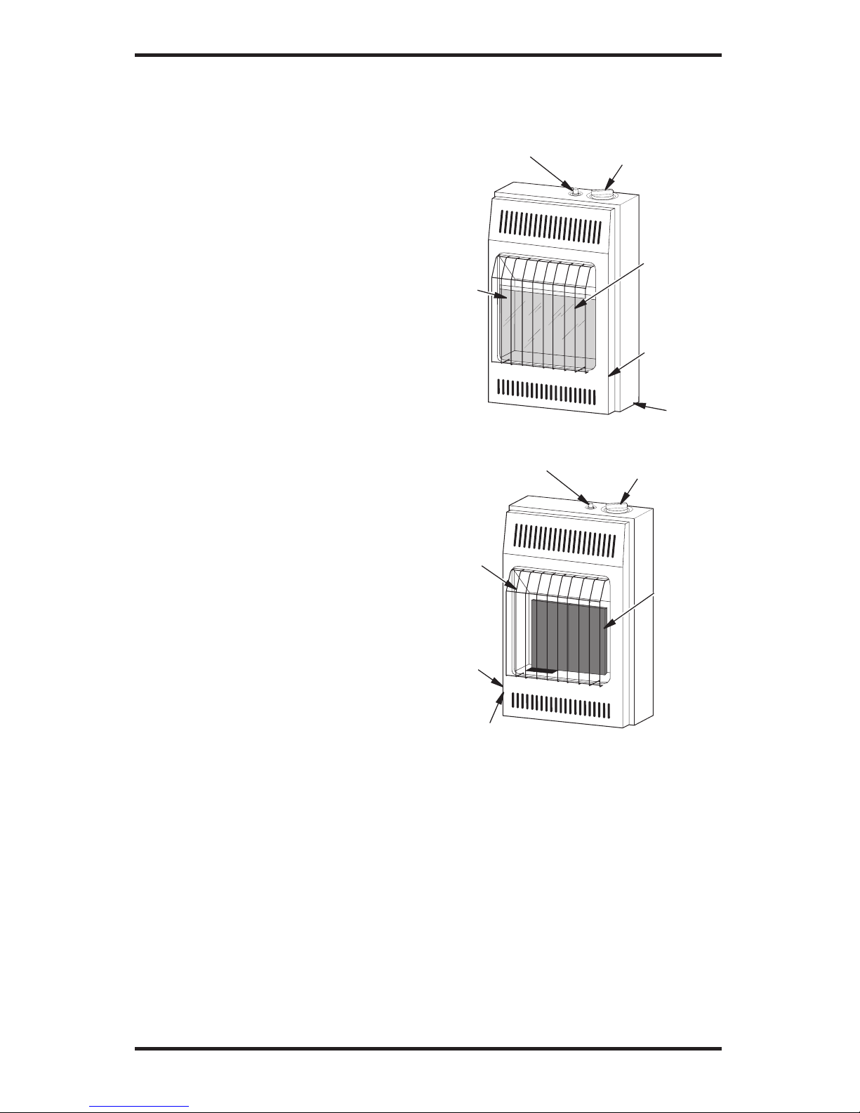
Figure 1 - Vent-Free Gas Heater
Infrared Heater
Control Knob
Piezo Ignitor
Button
Grill
Guard
Front
Panel
Burners
Heater
Cabinet
Control Knob
Piezo Ignitor
Button
Glass
Panel
Front
Panel
Heater
Cabinet
Grill
Guard
PRODUCT
IDENTIFICATION
PRODUCT FEATURES
SAFETY DEVICE
This heater has a pilot with an Oxygen Depletion Sensing (ODS) safety shutoff system. The
ODS/pilot is a required feature for vent-free room
heaters. The ODS/pilot shuts off the heater if there
is not enough fresh air.
PIEZO IGNITION SYSTEM
This heater has a piezo ignitor. This system requires no matches, batteries, or other sources to
light heater.
www.desatech.com
110720-01G 5
LOCAL CODES
Install and use heater with care. Follow all local codes. In the absence of local codes, use the
latest edition of National Fuel Gas Code ANSI
Z223.1/NFPA 54*.
*Available from:
American National Standards Institute, Inc.
1430 Broadway
New York, NY 10018
National Fire Protection Association, Inc.
Batterymarch Park
Quincy, MA 02269
AIR FOR VENTILATION
AND COMBUSTION
WARNING: This heater shall
not be installed in a confined
space or unusually tight con
struction unless provisions are
provided for adequate combus
tion and ventilation air. Read the
following instructions to insure
proper fresh air for this and
other fuel-burning appliances
in your home.
Todayʼs homes are built more energy efficient
than ever. New materials, increased insulation, and
new construction methods help reduce heat loss
in homes. Home owners weather strip and caulk
around windows and doors to keep the cold air out
and the warm air in. During heating months, home
owners want their homes as airtight as possible.
While it is good to make your home energy effi
cient, your home needs to breathe. Fresh air must
enter your home. All fuel-burning appliances need
fresh air for proper combustion and ventilation.
Exhaust fans, fireplaces, clothes dryers, and fuel
burning appliances draw air from the house to
operate. You must provide adequate fresh air for
these appliances. This will insure proper venting
of vented fuel-burning appliances.
PROVIDING ADEQUATE
VENTILATION
The following are excerpts from National Fuel
Gas Code, ANSI Z223.1/NFPA 54, Section 5.3,
Air for Combustion and Ventilation.
All spaces in homes fall into one of the three following ventilation classifications:
1. Unusually Tight Construction
2. Unconfined Space
3. Confined Space
The information on pages 5 through 7 will help
you classify your space and provide adequate
ventilation.
Unusually Tight Construction
The air that leaks around doors and windows may
provide enough fresh air for combustion and ven
tilation. However, in buildings of unusually tight
construction, you must provide additional fresh air.
Unusually tight construction is defined as
construction where:
a. walls and ceilings exposed to the out
-
side atmosphere have a continuous
water vapor retarder with a rating of
one perm (6 x 10
-11
kg per pa-sec-m2) or
less with openings gasketed or sealed
and
b. weather stripping has been added on
openable windows and doors and
c. caulking or sealants are applied to
areas such as joints around window
and door frames, between sole plates
and floors, between wall-ceiling joints,
between wall panels, at penetrations
for plumbing, electrical, and gas lines,
and at other openings.
If your home meets all of the three criteria
above, you must provide additional fresh air.
See Ventilation Air From Outdoors, page 7.
If your home does not meet all of the three
criteria above, proceed to Determining Fresh-
Air Flow For Heater Location, page 6.
Confined and Unconfined Space
The National Fuel Gas Code, ANSI Z223.1/NFPA
54 defines a confined space as a space whose
volume is less than 50 cubic feet per 1,000 Btu
per hour (4.8 m
3
per kw) of the aggregate input
rating of all appliances installed in that space and
an unconfined space as a space whose volume is
not less than 50 cubic feet per 1,000 Btu per hour
(4.8 m
3
per kw) of the aggregate input rating of
all appliances installed in that space. Rooms com
municating directly with the space in which the
appliances are installed*, through openings not
furnished with doors, are considered a part of the
unconfined space.
* Adjoining rooms are communicating only if
there are doorless passageways or ventilation grills
between them.
www.desatech.com
110720-01G
6
AIR FOR COMBUSTION
AND VENTILATION
Continued
DETERMINING FRESH-AIR FLOW
FOR FIREPLACE LOCATION
Determining if You Have a Confined or
Unconfined Space
Use this work sheet to determine if you have a
confined or unconfined space.
Space: Includes the room in which you will install
fireplace plus any adjoining rooms with doorless passageways or ventilation grills between the rooms.
1. Determine the volume of the space (length x
width x height).
Length x Width x Height =__________cu. ft.
(volume of space)
Example: Space size 20 ft. (length) x 16 ft.
(width) x 8 ft. (ceiling height) = 2,560 cu. ft.
(volume of space)
If additional ventilation to adjoining room is
supplied with grills or openings, add the volume
of these rooms to the total volume of the space.
2. Multiply the space volume by 20 to determine
the maximum Btu/Hr the space can support.
__________ (volume of space) x 20 = (Maxi-
mum Btu/Hr the space can support)
Example: 2,560 cu. ft. (volume of space) x 20 =
51,200 (maximum Btu/Hr the space can support)
3. Add the Btu/Hr of all fuel burning appliances in
the space.
Vent-free heater
__________ Btu/Hr
Gas water heater*
__________ Btu/Hr
Gas furnace
__________ Btu/Hr
Vented gas heater
__________ Btu/Hr
Gas fireplace logs
__________ Btu/Hr
Other gas appliances* + ________
Btu/Hr
Total = ________
Btu/Hr
* Do not include direct-vent gas appliances. Di
rect-vent draws combustion air from the outdoors
and vents to the outdoors.
Example:
Gas water heater ______________ Btu/Hr
Vent-free heater + _____________
Btu/Hr
Total = _____________
Btu/Hr
4. Compare the maximum Btu/Hr the space can
support with the actual amount of Btu/Hr used.
_________
Btu/Hr (maximum the space can support)
_________
Btu/Hr (actual amount of Btu/Hr used)
Example: 51,200 Btu/Hr (maximum the space
can support)
60,000 Btu/Hr (actual amount of
Btu/Hr used)
The space in the example is a confined space because
the actual Btu/Hr used is more than the maximum
Btu/Hr the space can support. You must provide ad
-
ditional fresh air. Your options are as follows:
A. Rework worksheet, adding the space of an adjoin-
ing room. If the extra space provides an unconfined
space, remove door to adjoining room or add
ventilation grills between rooms. See Ventilation
Air From Inside Building.
B. Vent room directly to the outdoors. See Ventila
-
tion Air From Outdoors, page 7.
C. Install a lower Btu/Hr heater, if lower Btu/Hr size
makes room unconfined.
If the actual Btu/Hr used is less than the maximum
Btu/Hr the space can support,
the space is an unconfined space. You will need no additional fresh air
ventilation.
WARNING: If the area in
which the heater may be operated is smaller than that defined
as an unconfined space or if the
building is of unusually tight
construction, provide adequate
combustion and ventilation air
by one of the methods described
in the National Fuel Gas Code,
ANSI Z223.1/NFPA 54 Section 5.3
or applicable local codes.
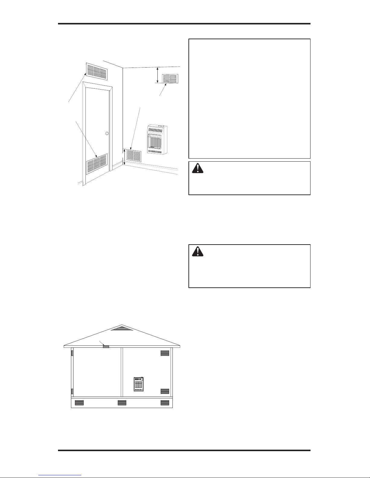
VENTILATION AIR
Ventilation Air From Inside Building
This fresh air would come from an adjoining un
confined space. When ventilating to an adjoining
unconfined space, you must provide two permanent
openings: one within 12" of the ceiling and one
within 12" of the floor on the wall connecting the
two spaces (see options 1 and 2, Figure 2, page 7).
You can also remove door into adjoining room (see
option 3, Figure 2, page 7). Follow the National Fuel
Gas Code, ANSI Z223.1/NFPA 54, Section 5.3, Air
for Combustion and Ventilation for required size
of ventilation grills or ducts.
50,000
10,000
60,000
www.desatech.com
110720-01G 7
Ventilation Air From Outdoors
Provide extra fresh air by using ventilation grills or
ducts. You must provide two permanent openings:
one within 12" of the ceiling and one within 12"
of the floor. Connect these items directly to the
outdoors or spaces open to the outdoors. These
spaces include attics and crawl spaces. Follow the
National Fuel Gas Code, ANSI Z223.1/NFPA 54,
Section 5.3, Air for Combustion and Ventilation for
required size of ventilation grills or ducts.
IMPORTANT: Do not provide openings for inlet
or outlet air into attic if attic has a thermostatcontrolled power vent. Heated air entering the attic
will activate the power vent.
Or
Remove
Door into
Adjoining
Room,
Option 3
Ventilation Grills
Into Adjoining Room,
Option 2
12"
12"
Ventilation
Grills
into Adjoining
Room,
Option 1
Figure 2 - Ventilation Air from Inside
Building
Outlet
Air
Ve
ntilated
Attic
Outlet
A
ir
Inlet
Air
Inlet Air
Ve
ntilated
Crawl Space
To
Crawl
Space
To Attic
Figure 3 - Ventilation Air from Outdoors
AIR FOR COMBUSTION
AND VENTILATION
Continued
INSTALLATION
NOTICE: This heater is intended
for use as supplemental heat.
Use this heater along with your
primary heating system. Do not
install this heater as your pri
mary heat source. If you have a
central heating system, you may
run system’s circulating blower
while using heater. This will help
circulate the heat throughout the
house. In the event of a power
outage, you can use this heater
as your primary heat source.
WARNING: A qualified service person must install heater.
Follow all local codes.
CHECK GAS TYPE
Use only the correct type of gas (natural or propane/LP). If your gas supply is not the correct gas
type, do not install heater. Call dealer where you
bought heater for proper type heater.
WARNING: This appliance
is equipped for (natural or pro
pane/LP) gas. Field conversion
is not permitted.
INSTALLATION ITEMS
Before installing heater, make sure you have the
items listed below.
• for propane/LP gas, external regulator (supplied
by installer)
• piping (check local codes)
• sealant (resistant to propane/LP gas)
• equipment shutoff valve *
• ground joint union
• sediment trap
• tee joint
• pipe wrench
• for natural gas, test gauge connection*
* A CSA design-certified equipment shutoff valve
with 1/8" NPT tap is an acceptable alternative to
test gauge connection. Purchase the optional CSA
design-certified equipment shutoff valve from your
dealer. See
Accessories, page 35.
www.desatech.com
110720-01G
8
LOCATING HEATER
This heater is designed to be mounted on a wall.
WARNING: Maintain the
minimum clearances shown
in Figure 4. If you can, provide
greater clearances from floor,
ceiling, and joining wall.
WARNING: Never install the
heater
• in a bathroom (10,000 Btu/hr
only. 6,000 Btu/hr models are
allowed in a bathroom. Check
local codes.)
• in a recreational vehicle
• where curtains, furniture,
clothing, or other flammable
objects are less than 36 inches
from the front, top, or sides of
the heater
• as a fireplace insert
• in high traffic areas
• in windy or drafty areas
INSTALLATION
Continued
CAUTION: This heater creates warm air currents. These
currents move heat to wall sur
faces next to heater. Installing
heater next to vinyl or cloth wall
coverings or operating heater
where impurities (such as, but
not limited to, tobacco smoke,
aromatic candles, cleaning fluids, oil or kerosene lamps, etc.) in
the air exist, may discolor walls
or cause odors.
IMPORTANT: Vent-free heaters add moisture to
the air. Although this is beneficial, installing heater
in rooms without enough ventilation air may cause
mildew to form from too much moisture. See
Air
for Combustion and Ventilation, page 5.
CAUTION: If you install the
heater in a home garage
• heater pilot and burner must
be at least 18 inches above
floor
• locate heater where moving
vehicle will not hit it
For convenience and efficiency, install heater
• where there is easy access for operation, inspec
-
tion, and service
• in coldest part of room
THERMOSTAT SENSING BULB
(Thermostat Models Only)
The thermostat sensing bulb is located inside the
heater. Do not move this bulb during installation
or operation of the heater.
36"
3"
CEILING
Minimum
Minimum To Top Surface
Of Carpeting, Tile Or Other
6" Blueflame
8" Plaque
Minimum
From
Sides Of
Heater
Right
Side
Left
Side
Figure 4 - Mounting Clearances As
Viewed From Front of Heater
Minimum To
Top Surface
Of Carpeting,
Tile Or Other
Combustible
Material
www.desatech.com
110720-01G 9
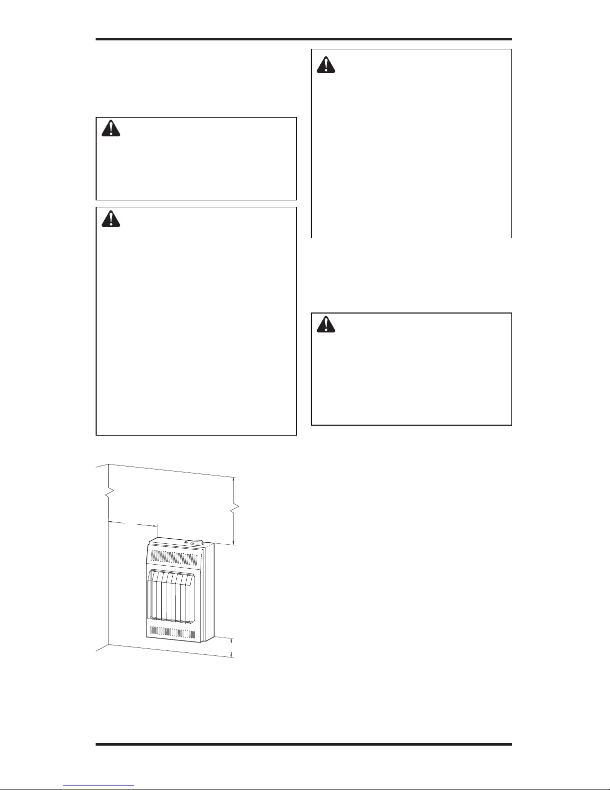
INSTALLING HEATER TO WALL
Marking Screw Locations
1. Determine where you will locate heater.
WARNING: Maintain mini-
mum clearances shown in Figure
5. If you can, provide greater
clearances from floor and joining wall.
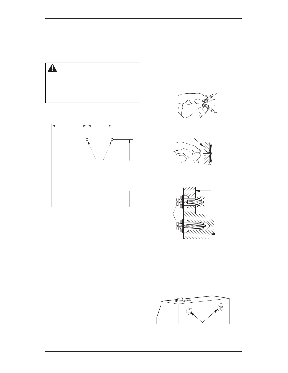
2. Mark two mounting screw locations on wall
(see Figure 5).
INSTALLATION
Continued
Figure 5 - Mounting Screw Locations
Mounting
Screw
Locations
8 7/8"
Blue Flame
10 7/8" Plaque
Minimum To
Maintain 6"
Clearance From
Wall
7 3/4"
20 1/4"
Minimum To
Maintain 3"
Clearance
From Floor
FLOOR
JOINING WALL
Installing Two Mounting Screws
Note: Wall anchors and mounting screws are
in hardware package. The hardware package is
provided with heater.
Attaching to Wall Stud Method
For attaching mounting screw to wall stud
1. Drill hole at marked location using 9/64"
drill bit.
2. Insert mounting screw into wall stud.
3. Tighten screw until 1/16" space (thickness of
penny) is between screwhead and wall.
Attaching to Wall Anchor Method
Follow instructions below to attach mounting
screws to hollow walls (wall areas between studs)
or solid walls (concrete or masonry).
1. Drill holes at marked locations using 5/16"
drill bit. For solid walls (concrete or masonry),
drill at least 1 1/4" deep.
2. Fold wall anchor (see Figure 6).
3. Insert wall anchor (wings first) into hole. Tap
anchor flush to wall.
4. For thin walls (1/2" or less), insert red key
into wall anchor. Push red key to “pop” open
anchor wings (see Figure 7).
IMPORTANT: Do not hammer key! For thick
walls (over 1/2" thick) or solid walls, do not
pop open wings.
5. Tighten two screws until 1/16" space (thick
ness of penny) is between screwheads and wall
(see Figure 8).
Figure 6 - Folding Anchor
Thin Walls (1/4" to 1/2" thick)
Figure 7 - Popping Open Anchor Wings
For Thin Walls
Figure 8 - Tightening Anchors
Thin or
Thick Wall
(thick wall
shown)
Solid
Wall
1/16"
Space
Placing Heater On Mounting Screws
1. Locate two keyhole slots on back panel of
heater (see Figure 9).
2. Place large openings of slots over screwheads.
Slide heater down until screws are in small
portion of slots.
Figure 9 - Location Of Keyhole Slots On
Back Panel Of Heater
Keyhole Slots
www.desatech.com
110720-01G
10
INSTALLATION
Continued
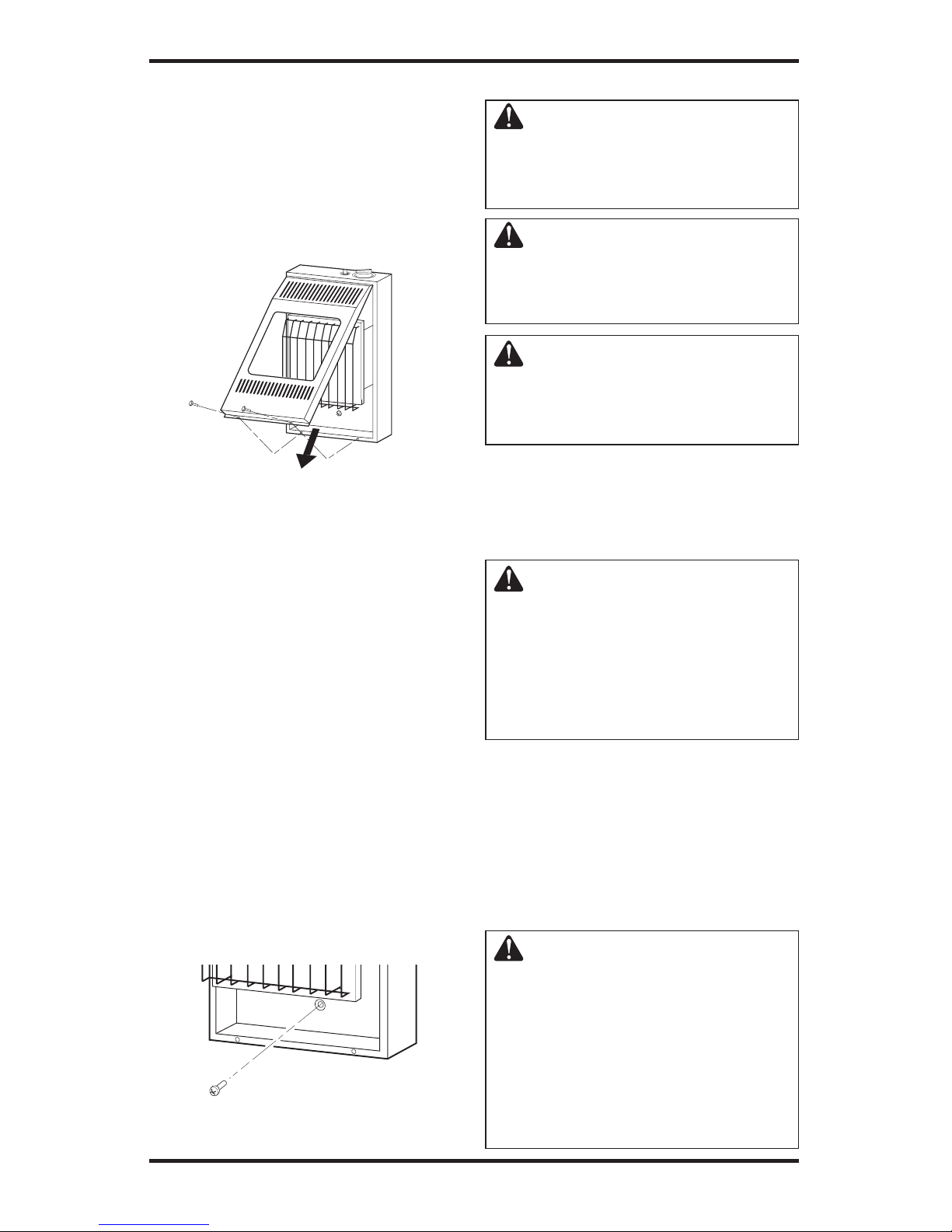
Removing Front Panel Of Heater
1. Remove two screws near bottom corners of
front panel.
2. Lift straight up on grill guard until it stops.
Grill guard will slide up about 1/4".
3. Pull bottom of front panel forward, then down.
Figure 10 - Removing Front Panel Of
Heater
Installing Bottom Mounting Screw
1. Locate bottom mounting hole. This hole is near
bottom on back panel of heater (see Figure 11).
2. Mark screw location on wall.
3. Remove heater from wall.
4. If installing bottom mounting screw into hol
low or solid wall, install wall anchor. Follow
steps 1 through 5 under Attaching To Wall
Anchor Method, page 9. If installing bottom
mounting screw into wall stud, drill hole at
marked location using 9/64" drill bit.
5. Replace heater on wall.
6. Insert bottom anchor screw through back
panel into bottom anchor or drilled hole (see
Figure 11).
7. Tighten screw until heater is firmly secured to
wall. Do not over tighten.
Note: Do not replace front panel at this time.
Replace front panel after making gas connec
tions and checking for leaks (see pages 10
through 13).
Figure 11 - Installing Bottom Mounting
Screw
CONNECTING TO GAS SUPPLY
WARNING: This appliance
requires a 3/8" NPT (National
Pipe Thread) inlet connection to
the pressure regulator.
WARNING: A qualified service person must connect heater
to gas supply. Follow all local
codes.
WARNING: For natural gas, never
connect heater to private (non-utility)
gas wells. This gas is commonly
known as wellhead gas.
IMPORTANT: For natural gas, check gas line
pressure before connecting heater to gas line. Gas
line pressure must be no greater than 10.5 inches of
water. If gas line pressure is higher, heater regulator damage could occur.
CAUTION: For propane/LP
gas, never connect heater directly
to the propane/LP supply. This
heater requires an external regu
lator (not supplied). Install the
external regulator between the
heater and propane/LP supply.
For propane/LP gas, the installer must supply an
external regulator. The external regulator will
reduce incoming gas pressure. You must reduce
incoming gas pressure to between 11 and 14 inches
of water. If you do not reduce incoming gas pres
sure, heater regulator damage could occur. Install
external regulator with the vent pointing down as
shown in Figure 12, page 11. Pointing the vent
down protects it from freezing rain or sleet.
CAUTION: Use only new,
black iron or steel pipe. Inter
nally-tinned copper tubing may
be used in certain areas. Check
your local codes. Use pipe of
large enough diameter to allow
proper gas volume to heater. If
pipe is too small, undue loss of
volume will occur.
www.desatech.com
110720-01G 11
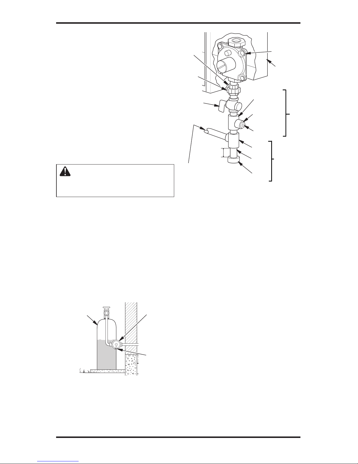
Installation must include equipment shutoff valve,
union, and plugged 1/8" NPT tap. Locate NPT tap
within reach for test gauge hook up. NPT tap must
be upstream from heater (see Figure 13).
IMPORTANT: Install an equipment shutoff valve
in an accessible location. The equipment shutoff
valve is for turning on or shutting off the gas to
the appliance.
Check your building codes for any special re
quirements for locating equipment shutoff valve
to fireplaces.
Apply pipe joint sealant lightly to male NPT
threads. This will prevent excess sealant from
going into pipe. Excess sealant in pipe could result
in clogged heater valves.
WARNING: Use pipe joint
sealant that is resistant to liquid
petroleum (LP) gas.
We recommend that you install sediment trap in
supply line as shown in Figure 13. Locate sediment
trap where it is within reach for cleaning. Install
in piping system between fuel supply and heater.
Locate sediment trap where trapped matter is not
likely to freeze. A sediment trap traps moisture and
contaminants. This keeps them from going into
heater controls. If sediment trap is not installed or is
installed wrong, heater may not run properly.
IMPORTANT: Hold pressure regulator with
wrench when connecting it to gas piping and/or
fittings. Do not over tighten pipe connection to
regulator. The regulator body could be damaged.
INSTALLATION
Continued
Propane/LP
Supply Tank
Figure 12 - External Regulator With Vent
Pointing Down (propane/LP systems
only)
External
Regulator
Vent
Pointing
Down
Figure 13 - Gas Connection
* A CSA design-certified equipment shutoff valve
with 1/8" NPT tap is an acceptable alternative to
test gauge connection. Purchase the optional CSA
design-certified equipment shutoff valve from your
dealer. See Accessories, page 35.
Tee Joint
Reducer
Bushing to
1/8" NPT
1/8" NPT
Plug Tap
Tee
Joint
Pipe
Nipple
Cap
3/8"
NPT
Pipe
Nipple
Ground
Joint
Union
3"
Minimum
Natural Gas
From Gas Meter
(4" or 5" W.C. to 10.5"
W.C. Pressure [See
Specifications, page 34])
Propane/LP
From External Regulator
(11" W.C. to 14" W.C.
Pressure)
Equipment
Shutoff
Valve*
Test Gauge Connection*
Pressure
Regulator
Heater
Cabinet
Sediment
Trap
 Loading...