

Page 1
UNVENTED (VENT-FREE)
UNIVERSAL FIREBOX
TM
OWNER’S OPERATION AND
INSTALLATION MANUAL
For more information, visit www.desatech.com
For more information, visit www.desatech.com
V50S, V50SH, and VFB50NC Vent-Free Fireboxes
WARNING: If the information in this manual is not
followed exactly, a fire or explosion may result causing property damage, personal injury, or loss of life.
— Do not store or use gasoline or other flammable
vapors and liquids in the vicinity of this or any
other appliance.
— WHAT TO DO IF YOU SMELL GAS
• Do not try to light any appliance.
• Do not touch any electrical switch; do not use
any phone in your building.
• Immediately call your gas supplier from a
neighbor’s phone. Follow the gas supplier’s
instructions.
• If you cannot reach your gas supplier, call the
fire department.
— Installation and service must be performed by a
qualified installer, service agency, or the gas
supplier.
WARNING: Improper installation, adjustment, alteration, service, or maintenance can cause injury or property
damage. Refer to this manual for correct installation and operational procedures. For assistance or additional
information consult a qualified installer,
service agency, or the gas supplier.
WARNING: FOR USE ONLY WITH A
LISTED DECORATIVE TYPE UNVENTED
ROOM HEATER. DO NOT BUILD A
WOOD FIRE.
This firebox has been tested and approved by CSA International under
Z21.91-2001 for use with approved
ANSI Z21.11.2 decorative type
unvented room heater.
This appliance may be installed in an aftermarket*, permanently located, manufactured
(mobile) home, where not prohibited by local codes.
This appliance is only for use with the type of gas indicated on the rating plate. This appliance
is not convertible for use with other gases.
*Aftermarket: Completion of sale, not for purpose of resale, from the manufacturer
Save this manual for future reference.
Save this manual for future reference.
Page 2
TABLE OF CONTENTS
SAFETY INFORMATION
2
TABLE OF CONTENTS
SAFETY INFORMATION ............................................................ 2
LOCAL CODES........................................................................... 3
PRODUCT FEATURES .............................................................. 3
LOCATING FIREBOX ................................................................. 3
PRODUCT SPECIFICATIONS.................................................... 4
AIR FOR COMBUSTION AND VENTILATION ........................... 5
INSTALLATION ........................................................................... 8
SAFETY INFORMATION
WARNINGS
IMPORTANT: Read this owner’s manual carefully and
completely before trying to assemble, operate, or
service this firebox. Improper use of this firebox can
cause serious injury or death from burns, fire, explosion, electrical shock, or carbon monoxide poisoning.
WARNING: Carefully review the instructions supplied with the decorative type unvented room heater
for the minimum fireplace size requirement.
DO NOT INSTALL THE APPLIANCE IN THIS FIREBOX, UNLESS THIS FIREBOX MEETS THE MINIMUM
DIMENSIONS REQUIRED FOR THE INSTALLATION.
ILLUSTRATED PARTS BREAKDOWN AND PARTS LIST ....... 12
TECHNICAL SERVICE ............................................................. 14
REPLACEMENT PARTS .......................................................... 14
ACCESSORIES ........................................................................ 14
OWNER'S REGISTRATION FORM .......................................... 15
WARRANTY INFORMATION...................................... Back Cover
Do not place clothing or other flammable material on
or near the appliance. Never place any objects in the
firebox or on logs.
Firebox front and screen becomes very hot when
running firebox. Keep children and adults away from
hot surfaces to avoid burns or clothing ignition.
Firebox will remain hot for a time after shutdown.
Allow surfaces to cool before touching.
Carefully supervise young children when they are in
the room with firebox.
WARNING: Any change to this firebox or its
controls can be dangerous.
WARNING: Do not allow fans to blow directly into
the firebox. Avoid any drafts that alter burner flame
patterns. Ceiling fans can create drafts that alter
burner flame patterns. Altered burner patterns can
cause sooting.
WARNING: Do not use a blower insert, heat
exchanger insert, or other accessory not approved
for use with this firebox.
For more information, visit www.desatech.com
For more information, visit www.desatech.com
You must operate this fireplace with the provided
fireplace screen, hood, if provided, in place. Make
sure these parts are in place and screens are closed
before running firebox. The supplied hood may not
be replaced with a hood which may be provided with
a log heater.
Keep the fireplace area clear and free from combustible materials, gasoline, and other flammable vapors
and liquids.
110749-01A
Page 3

SAFETY INFORMATION
LOCAL CODES
PRODUCT FEATURES
LOCATING FIREBOX
3
3
SAFETY INFORMATION
Continued
1. Do not use this firebox as a wood-burning fireplace. Use only
decorative unvented room heaters (log sets).
2. Do not add extra logs or ornaments such as pine cones, vermiculite, or rock wool. Using these added items can cause sooting.
3. Use only the provided hood, or appropriate hood accessory.
See Accessories, page 14.
4. Vent-free gas log heaters installed in these fireboxes require
fresh air ventilation to run properly. See Air for Combustion
and Ventilation, pages 5 through 7.
5. Do not run vent-free heaters installed in these fireboxes
• where flammable liquids or vapors are used or stored
• under dusty conditions
6. Do not use this firebox to cook food or burn paper or other
objects.
7. Turn unit off and let cool before servicing. Only a qualified
service person should service and repair firebox.
8. Operating vent-free heaters installed in these fireboxes above
elevations of 4,500 feet could cause pilot outage.
9. Do not use the firebox if it has been under water.
LOCAL CODES
Install and use fireplace with care. Follow all local codes. In the
absence of local codes, use the latest edition of The National Fuel Gas
Code ANSI Z223.1/NFPA 54*. Firebox must be electrically grounded
in accordance with the National Electrical Code, ANSI/NFPA70
(latest edition).
*Available from:
American National Standards Institute, Inc.
1430 Broadway
New York, NY 10018
PRODUCT FEATURES
OPERATION
This firebox is designed for use with approved ANSI Z21.11.2
decorative type unvented room heaters. (Physical size limitations
apply. Refer to minimum firebox requirements supplied with log
heater.) It requires no outside venting or chimney making installation
easy and inexpensive. When used without the blower, the firebox
requires no electricity making it ideal for emergency backup heat.
REFRACTORY BRICK LINER
Your firebox features a concrete refractory brick liner. As with all
concrete liners, this liner may develop slight cracks when exposed
to heat. These cracks will not affect the performance of the fireplace
or vent-free gas logs.
LOCATING FIREBOX
PLANNING
Plan where you will install the firebox. This will save time and
money later when you install the firebox. Before installation,
consider the following:
1. Where the firebox will be located. Allow for wall and ceiling
clearances (see Installation Clearances, pages 8 and 9).
2. Everything needed to complete installation.
3. These models CANNOT be installed in a bedroom unless the
maximum Btu rating of the installed vent-free log set is less
than 10,000 Btu/hr.
4. Proper air for combustion and ventilation (page 5).
110749-01A
National Fire Protection Association, Inc.
Batterymarch Park
Quincy, MA 02269
For more information, visit www.desatech.com
For more information, visit www.desatech.com
Page 4
PRODUCT SPECIFICATIONS
4
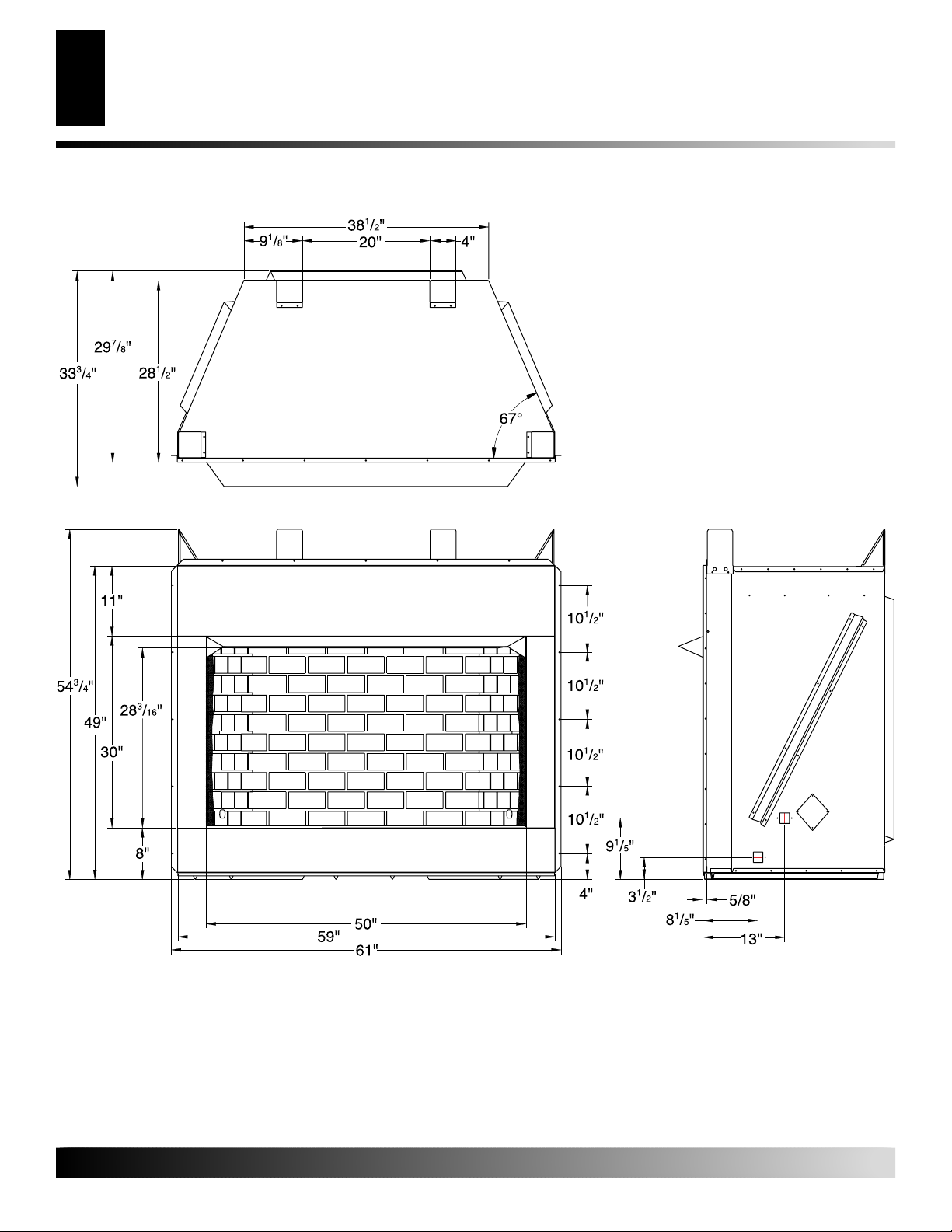
PRODUCT SPECIFICATIONS
Firebox Top View
Figure 1 - Firebox Dimensions
For more information, visit www.desatech.com
For more information, visit www.desatech.com
Front View
Side View
110749-01A
Page 5
AIR FOR COMBUSTION AND
VENTILATION
WARNING: This firebox shall not be installed in a
confined space or unusually tight construction unless provisions are provided for adequate combustion and ventilation air. Read the following instructions to insure proper fresh air for this and other fuelburning appliances in your home.
Today’s homes are built more energy efficient than ever. New
materials, increased insulation, and new construction methods help
reduce heat loss in homes. Home owners weather strip and caulk
around windows and doors to keep the cold air out and the warm air
in. During heating months, home owners want their homes as
airtight as possible.
While it is good to make your home energy efficient, your home
needs to breathe. Fresh air must enter your home. All fuel-burning
appliances need fresh air for proper combustion and ventilation.
Exhaust fans, fireboxes, clothes dryers, and fuel burning appliances
draw air from the house to operate. You must provide adequate fresh
air for these appliances. This will insure proper venting of vented
fuel-burning appliances.
PROVIDING ADEQUATE VENTILATION
The following are excerpts from National Fuel Gas Code, ANSI
Z223.1/NFPA 54, Section 5.3, Air for Combustion and Ventilation.
All spaces in homes fall into one of the three following ventilation
classifications:
1. Unusually Tight Construction
2. Unconfined Space
3. Confined Space
The information on pages 5 through 7 will help you classify your
space and provide adequate ventilation.
AIR FOR COMBUSTION AND VENTILATION
Unusually tight construction is defined as construction
where:
a. walls and ceilings e xposed to the outside atmosphere
have a continuous water vapor retar der with a rating
of one perm (6 x 10
openings gasketed or sealed
b. weather stripping has been added on openable win-
dows and doors
c. caulking or sealants are applied to areas such as
joints around window and door frames, between sole
plates and floors, between wall-ceiling joints, between
wall panels, at penetrations for plumbing, electrical,
and gas lines, and at other openings.
If your home meets all of the three criteria above, you
must provide additional fresh air. See
From Outdoors
If your home does not meet all of the
proceed to
tion,
page 6.
Providing Adequate Ventilation
-11
kg per pa-sec-m2) or less with
and
and
Ventilation Air
, page 7.
three criteria above,
Determining Fresh-Air Flow for Firebox Loca-
5
5
Confined and Unconfined Space
The National Fuel Gas Code, ANSI Z223.1/NFPA 54 defines a
confined space as a space whose volume is less than 50 cubic feet
per 1,000 Btu per hour (4.8 m3 per kw) of the aggregate input rating
of all appliances installed in that space and an unconfined space as
a space whose volume is not less than 50 cubic feet per 1,000 Btu per
hour (4.8 m3 per kw) of the aggregate input rating of all appliances
installed in that space. Rooms communicating directly with the
space in which the appliances are installed*, through openings not
furnished with doors, are considered a part of the unconfined space.
* Adjoining rooms are communicating only if there are doorless
passageways or ventilation grills between them.
Unusually Tight Construction
The air that leaks around doors and windows may provide enough
fresh air for combustion and ventilation. However, in buildings of
unusually tight construction, you must provide additional fresh air.
For more information, visit www.desatech.com
For more information, visit www.desatech.com
110749-01A
Page 6
AIR FOR COMBUSTION AND VENTILATION
6
Determining Fresh-Air Flow For Heater Location
AIR FOR COMBUSTION AND
VENTILATION
Continued
DETERMINING FRESH-AIR FLOW FOR
FIREBOX LOCATION
Determining if You Have a Confined or
Unconfined Space
Use this work sheet to determine if you have a confined or unconfined space.
Space: Includes the room in which you will install heater plus any adjoining
rooms with doorless passageways or ventilation grills between the rooms.
1. Determine the volume of the space (length x width x height).
Length x Width x Height =___________ cu. ft. (volume of space)
Example:
height) = 3168 cu. ft. (volume of space)
If additional ventilation to adjoining room is supplied with grills or open-
ings, add the volume of these rooms to the total volume of the space.
2. Multiply the space volume by 20 to determine the maximum Btu/Hr
the space can support.
__________ (volume of space) x 20 = (Maximum Btu/Hr the space
Example:
Btu/Hr the space can support)
3. Add the Btu/Hr of all fuel burning appliances in the space.
* Do not include direct-vent gas appliances. Direct-vent draws combustion air from the outdoors and vents to the outdoors.
4. Compare the maximum Btu/Hr the space can support with the actual
amount of Btu/Hr used.
__________________ Btu/Hr (maximum the space can support)
__________________ Btu/Hr (actual amount of Btu/Hr used)
Example:
Space size 22 ft. (length) x 18 ft. (width) x 8 ft. (ceiling
can support)
3168 cu. ft. (volume of space) x 20 = 63,360 (maximum
Vent-free heater _____________ Btu/Hr
Gas water heater* _____________ Btu/Hr
Gas furnace _____________ Btu/Hr
Vented gas heater _____________ Btu/Hr
Gas fireplace logs _____________ Btu/Hr
Other gas appliances* + _____________ Btu/Hr
Total = _____________ Btu/Hr
Example:
Gas water heater _____________ Btu/Hr
Vent-free heater + _____________ Btu/Hr
Total = _____________ Btu/Hr
63,360 Btu/Hr (maximum the space can support)
79,000 Btu/Hr (actual amount of Btu/Hr used)
40,000
39,000
79,000
The space in the above example is a confined space because the actual Btu/
Hr used is more than the maximum Btu/Hr the space can support. You must
provide additional fresh air. Your options are as follows:
A. Rework worksheet, adding the space of an adjoining room. If the
extra space provides an unconfined space, remove door to adjoining
room or add ventilation grills between rooms. See V entilation Air Fr om
Inside Building, page 7.
B. Vent room directly to the outdoors. See Ventilation Air From Out-
doors, page 7.
C. Install a lower Btu/Hr heater, if lower Btu/Hr size makes room un-
confined.
If the actual Btu/Hr used is less than the maximum Btu/Hr the space can
support, the space is an unconfined space. You will need no additional fresh
air ventilation.
WARNING: If the area in which the heater may be
operated is smaller than that defined as an unconfined space or if the building is of unusually tight
construction, provide adequate combustion and ventilation air by one of the methods described in the
National Fuel Gas Code, ANSI Z223.1/NFPA 54 Section 5.3
or applicable local codes
.
For more information, visit www.desatech.com
For more information, visit www.desatech.com
110749-01A
Page 7

AIR FOR COMBUSTION AND
VENTILATION
Continued
AIR FOR COMBUSTION AND VENTILATION
Ventilation Air
7
7
VENTILATION AIR
Ventilation Air From Inside Building
This fresh air would come from an adjoining unconfined space.
When ventilating to an adjoining unconfined space, you must
provide two permanent openings: one within 12" of the ceiling and
one within 12" of the floor on the wall connecting the two spaces
(see options 1 and 2, Figure 3). You can also remove door into
adjoining room (see option 3, Figure 2). Follow the National Fuel
Gas Code, ANSI Z223.1/NFPA 54, Section 5.3, Air for Combustion
and Ventilation for required size of ventilation grills or ducts.
Ventilation Air From Outdoors
Provide extra fresh air by using ventilation grills or ducts. You must
provide two permanent openings: one within 12" of the ceiling and
one within 12" of the floor. Connect these items directly to the
outdoors or spaces open to the outdoors. These spaces include attics
and crawl spaces. Follow the National Fuel Gas Code, ANSI
Z223.1/NFPA 54, Section 5.3, Air for Combustion and Ventilation
for required size of ventilation grills or ducts.
IMPORTANT:
attic if attic has a thermostat-controlled power vent. Heated air
entering the attic will activate the power vent.
Do not provide openings for inlet or outlet air into
12"
Ventilation
Grills
Into Adjoining
Room,
Option 1
Figure 2 - Ventilation Air from Inside Building
Outlet
Air
Or
Remove
Door into
Adjoining
Room,
Option
3
Outlet
Air
Ventilation Grills
Into Adjoining Room,
Option 2
12"
Ventilated
Attic
To Attic
110749-01A
Inlet
Air
Inlet Air
Figure 3 - Ventilation Air from Outdoors
For more information, visit www.desatech.com
For more information, visit www.desatech.com
To
Crawl
Space
Ventilated
Crawl Space
Page 8

INSTALLATION
8
Installation Clearances
INSTALLATION
WARNING: A qualified service person must in-
stall firebox. Follow all local codes.
WARNING: Never install the firebox
• in a bedroom or bathroom*
• in a recreational vehicle
• where curtains, furniture, clothing, or other flam-
mable objects are less than 42 inches from the
front, top, or sides of the firebox
• in high traffic areas
• in windy or drafty areas
* Unless the installed log set is rated at 10,000 Btu/Hr
or less.
CAUTION: Log heaters installed in this firebox
create warm air currents. These currents move heat
to wall surfaces next to firebox. Installing firebox next
to vinyl or cloth wall coverings or operating firebox
where impurities (such as, but not limited to, tobacco
smoke, aromatic candles, cleaning fluids, oil or kerosene lamps, etc.) in the air exist, may discolor walls
or cause odors.
NOTICE: The firebox identification label (including
model number, serial number, clearances, etc.) is
located on a chain under the bottom refractory.
IMPORTANT:
Although this is beneficial, installing firebox in rooms without
enough ventilation air may cause mildew to form from too much
moisture. See Air for Combustion and Ventilation, pages 5 through 7.
IMPORTANT:
log set will not work properly.
Note:
Your firebox is designed to be used in zero clearance
installations. Wall or framing material can be placed against any
exterior surface on the rear, sides, top or bottom of your firebox,
except where standoff spacers are integrally attached. If standoff
spacers are attached to your firebox, these spacers can be placed
directly against wall or framing materials. Use the dimensions
shown for rough opening to create the easiest installation.
Use dimensions shown for rough openings to create the easiest
installation (see Built-In Firebox Installation, page 9).
Vent-free gas log heaters add moisture to the air.
Make sure the firebox is level. If firebox is not level,
INSTALLATION CLEARANCES
WARNING: Maintain the minimum clearances. If
you can, provide greater clearances from floor, ceiling, and adjoining wall.
Carefully follow the instructions in column 2. This will ensure safe
installation.
Minimum Wall and Ceiling Clearances (see Figure 4)
A. Clearances from the side of the fireplace cabinet to any com-
bustible material and wall should follow diagram in Figure 4.
Example:
combustible material and protrudes 3 1/2" from the wall. This
combustible material must be 4" from the side of the fireplace
cabinet (see Figure 4).
B. Clearances from the top of the firebox opening to the ceiling
should not be less than 42 inches.
C. When the firebox is installed on carpeting or other combus-
tible material, other than wood flooring, the firebox should be
installed on a metal or wood panel extending the full width
and depth of the enclosure.
D. Clearances from the bottom of firebox to the floor is 0 inches.
These fireboxes can be installed as freestanding units against a wall
with approved cabinet mantels that may be available from your
retailer or supplier, or as a built-in unit. The clearances are the same
for either installation method.
CAUTION: Do not install the firebox directly on
carpet or vinyl.
The face of a mantel, bookshelf, etc. is made of
Example
*
*Minimum 16 inches from Side Wall
Figure 4 - Minimum Clearance for Combustible to Wall
For more information, visit www.desatech.com
For more information, visit www.desatech.com
110749-01A
Page 9

INSTALLATION
30"
59
1
/2"
(Inside to Inside)
55"
Continued
Mantel Clearances for Built-In Installation
If placing custom mantel above built-in firebox, you must meet the
minimum allowable clearance between mantel shelf and top of
firebox opening shown in Figure 5. These are the minimum allowable mantel clearances for a safe installation. Use larger clearances
wherever possible to minimize the heating of objects and materials
placed on the mantel.
CAUTION: Do not allow the vent-free gas log
heater to touch or extend beyond the fireplace screen.
NOTICE: Surface temperatures of adjacent walls and
mantels become hot during operation. Walls and
mantels above the firebox may become hot to the
touch. If installed properly, these temperatures meet
the requirement of the national product standard.
Follow all minimum clearances shown in this manual.
NOTICE: If your installation does not meet the minimum
clearances shown, you must do one of the following:
• raise the mantel to an acceptable height
• remove the mantel
Wall board or facing
material (above
firebox) may be of
combustible material,
including decorative
mantel ornaments or
other similar projections off of the facing
material.
Framing
Material
Firebox
Wire-mesh
Screen
Installation Clearances (Cont.)
INSTALLATION
Built-In Firebox Installation
Mantel Shelf
Note:
Any portion of the
mantel shelf must NOT
12"
6
1
extend beyond this profile.
3
/4"
1
/2"
Noncombustible
Material May
Project Off this
Surface above
the Firebox Hood
Supplied Firebox
Hood Must Be
Used at All Times
12" 16" 20"
Note:
All vertical
measurements are
from top of fireplace
hood opening to
bottom of mantel shelf.
These minimum
clearances replace any
other recommended
clearances supplied with
your ANSI Z21.11.2
approved gas logs.
9
9
BUILT-IN FIREBOX INSTALLATION
Built-in installation of this firebox involves installing firebox into a
framed-in enclosure. This makes the front of firebox flush with wall.
If installing a mantel above the firebox, you must follow the
clearances shown in Figure 5. Follow these instructions to install the
firebox in this manner.
1. Frame in rough opening. The firebox framing should be constructed of 2 x 4 lumber or heavier. Use dimensions and rough
opening layout in Figure 6a. Adjust framing so that firebox
flushes with finished wall surface. If installing in a corner, use
dimensions in Figures 6b for rough opening.
2. Install gas piping to firebox location. See Installing Gas Line on
page 11 and Connecting to Gas Supply in log set owner’s manual.
3. Carefully set firebox in front of rough opening with back of
firebox inside wall opening.
4. Carefully insert firebox into rough opening.
5. Attach firebox to wall studs using nails or wood screws through
holes in nailing flange (see Figure 7, page 10).
6. Install and properly test gas log heater. Follow installation instructions included with the vent-free gas log heater that is
being installed.
110749-01A
For more information, visit www.desatech.com
For more information, visit www.desatech.com
Figure 5 - Minimum Mantel Clearances for Built-In Installation
Figure 6a
Figure 6b
Figure 6 - Rough Opening for Installing in Wall
Page 10
INSTALLATION
10
Built-In Firebox Installation (Cont.)
Installing Firebox Using Optional Mantels Available from Retailer or Custom Built
INSTALLATION
Continued
IMPORTANT:
When finishing your firebox, combustible materials
such as wall board, gypsum board, sheet rock, drywall, plywood, etc.
may be butted up next to the sides and top of the firebox. Combustible
materials should never overlap the firebox front facing.
WARNING: Do not allow any combustible materi-
als to overlap the firebox front facing.
Nails or
Wood
Screws
Nailing
Flanges
Figure 7 - Attaching Firebox to Wall Studs
IMPORTANT:
Noncombustible materials such as brick, tile, etc.
may overlap the front facing, but should never cover any necessary
openings like louvered slots.
WARNING: Do not allow noncombustible materials
to cover any necessary openings like louvered slots.
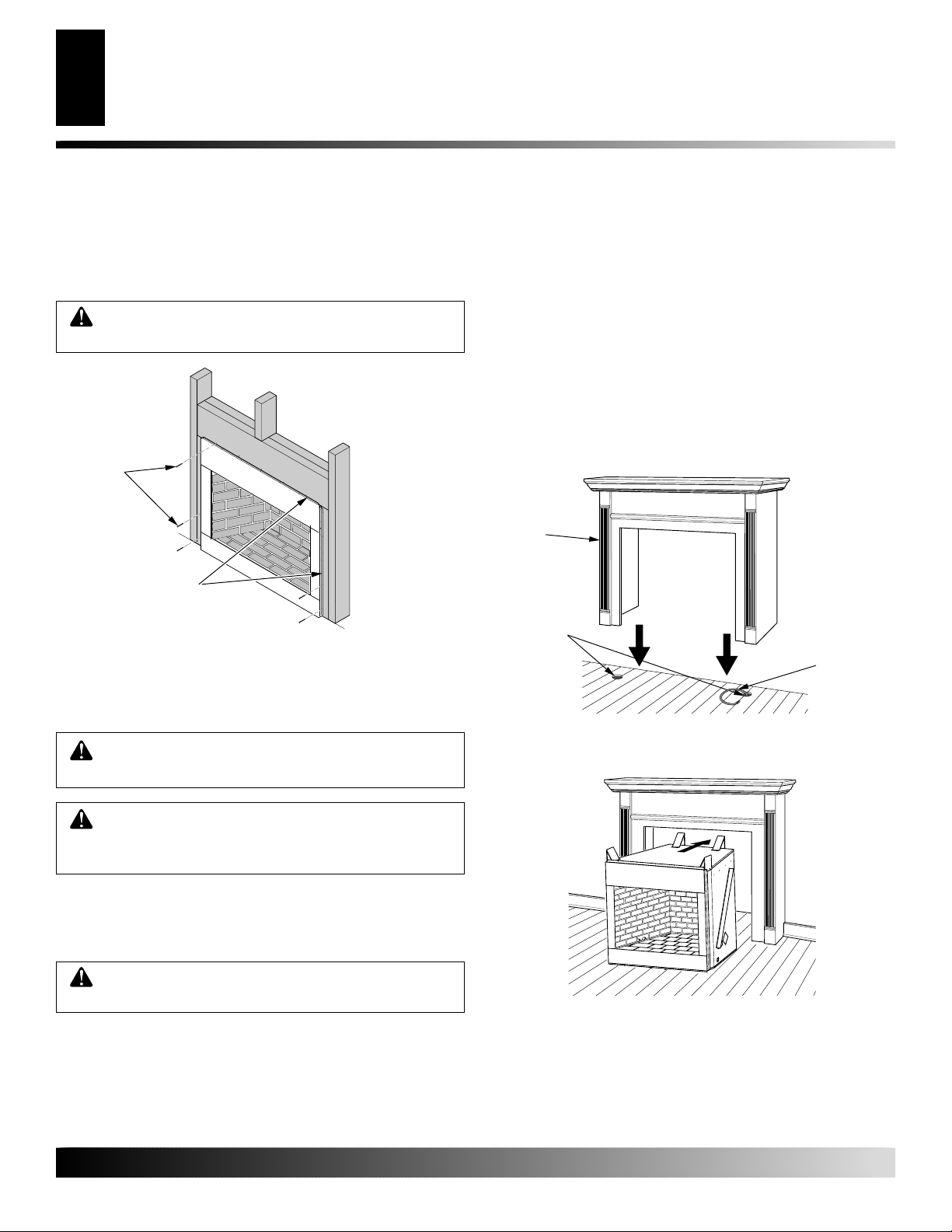
1. Assemble cabinet mantel as instructed.
2. Install gas piping to firebox location. See Installing Gas Line,
page 11. You may have to cut an access hole in the floor or
wall to run gas line to firebox. Make sure to locate access hole
so cabinet mantel will cover it when installed (see Figure 8).
3. Place cabinet mantel on floor in desired location. Make sure
mantel is flush against wall.
4. Carefully insert firebox into cabinet mantel. Be careful not to
scratch firebox, cabinet mantel, flooring, etc. when installing
(see Figure 9).
5. Install and properly test gas log heater. Follow installation instructions included with the vent-free gas log heater that is
being installed.
Cabinet
Mantel
Gas Line
Access Hole
(Either Side
of Firebox)
Figure 8 - Installing Cabinet Mantel (Mantel May Vary From
Illustration)
Gas
Piping
WARNING: Use only noncombustible mortar or
adhesives when overlapping the front facing with
noncombustible facing material.
INSTALLING FIREBOX USING OPTIONAL
MANTELS AVAILABLE FROM RETAILER OR
CUSTOM BUILT
WARNING: A qualified service person must install firebox. Follow all local codes.
This firebox may be installed using a cabinet mantel against a wall in
your home. The firebox and cabinet mantel can be installed directly
on the floor. Mantels may be available from your retailer or custom
built for your home.
For more information, visit www.desatech.com
For more information, visit www.desatech.com
Figure 9 - Inserting Firebox Into Cabinet Mantel (Mantel May
Vary From Illustration)
110749-01A
Page 11

INSTALLATION
Continued
INSTALLATION
Installing Gas Line
Installing Fireplace Hood and Screen
11
11
INSTALLING GAS LINE
WARNING: A qualified service person must connect heater to gas supply. Follow all local codes.
IMPORTANT:
owner’s manual for details on gas hookup.
You may run the gas line from either side of the firebox (see
Figure 11). Decide which side you want to run the gas line from.
Note:
This is one option for installing shutoff valve. Check local
codes for equipment shutoff valve location requirements.
Locate the recessed knockout in one of the firebrick sidewall liners
(see Figures 10 and 11). Firmly tap the center of the knockout with
a chisel until it is released. Carefully chisel the rough edges of the
hole you have made to smooth edges. This hole will line up with the
hole in the outer casing.
Locate the recessed knockout in one of the firebrick sidewall liners (see
Figures 10 and 11). Firmly tap the center of the knockout with a chisel
until it is released. Carefully chisel the rough edges of the hole to
smooth edges. This hole will line up with the hole in the outer casing.
CAUTION: Do not use excessive force to remove
the knockout. Too much force may damage the firebrick concrete insert.
See Connecting to Gas Supply in your log set
13/8" Thick Liner
Firebrick Side Wall
Side
View
Remove
this Area
Knockout
Figure 11 - Location of Knockout for Gas Line
Chisel
INSTALLING FIREPLACE HOOD AND SCREEN
1. Attach hood to firebox using screws provided (see Figure 12).
2. Insert each rod through all rings located at top of screen.
3. Insert first rod into rear hole in left side of firebox. Fasten rod
to rear hole near center of firebox using #10 x 3/8" Phillips
screw provided (see Figure 13).
4. Insert other rod into front hole on right side of firebox and
fasten using remaining Phillips screw.
Equipment
Shutoff
Valves
(Install
One)
Knockout Locations
(Knock Out One Hole)
Gas Line Hole
Figure 10 - Installing Gas Line and Equipment Shutoff Valve
(Model May Vary From Illustration)
For more information, visit www.desatech.com
For more information, visit www.desatech.com
110749-01A
Screws
Figure 12 - Screw and Hood Placement
Rear Hole
Front Hole
Rod
Top View of
Rod Layout
Ring
Screen
Screw
Figure 13 - Installing Fireplace Screen
Page 12

12
ILLUSTRATED PARTS BREAKDOWN
ILLUSTRATED PARTS
BREAKDOWN
V50H, V50S, AND VFB50NC
13
12
1
7
28
9
10
6
11
1
2
1
3
4
29
5
31
8
16
38
37
32
36
35
23
25
24
30
34
20
14
17/18
19
6
33
19
25
26
22
21
For more information, visit www.desatech.com
For more information, visit www.desatech.com
110749-01A
Page 13

PARTS LIST
V50H, V50S, AND VFB50NC
This list contains replaceable parts used in your firebox. When
ordering parts, follow the instructions listed under Replacement
Parts on page 14 of this manual.
PARTS LIST
13
13
KEY PART
NO. NUMBER DESCRIPTION QTY.
1 23490 Top Spacer 4
2 110285-03 Fireplace Top 1
3 109731-01 Fireplace Top Insulation 2
4 109732-01 Insulation Pan 1
5 109720-01 Clearance Spacer 1
6 109720-02 Clearance Spacer 2
7 110461-01 Rear Insulation 1
8 110451-01 Right Insulation 1
9 110452-01 Left Insulation 1
10 109738-01 Pan Support Insulation Ring 1
11 110450-01 Firebox Top 1
12 109753-01 Firebox Surround 1
13 109714-01 Refractory Spacer 7
14 109754-01 Firebox Bottom 1
15 109721-01 Firebox Floor Assembly 1
16 20042 Cover Plate 2
17 109752-01 Gas Line One Conduit 2
18 109752-02 Gas Line Two Conduit 2
19 21171 Gas Line Cover 4
20 109871-01 Bottom Front Refractory 1
109871-02 Bottom Front Refractory, Red 1
109876-01 Bottom Front Refractory, H-Bone 1
109876-02 Bottom Front Refracory, Red H-Bone 1
21 109872-01 Bottom Rear Refractory 1
109872-02 Bottom Rear Refractory, Red 1
109877-01 Bottom Rear Refractory, H-Bone 1
109877-02 Bottom Rear Refractory, Red H-Bone 1
KEY PART
NO. NUMBER DESCRIPTION QTY.
22 109873-01 Bottom Right Refractory 1
109873-02 Bottom Right Refractory, Red 1
109878-01 Bottom Right Refractory, H-Bone 1
109878-02 Bottom Right Refractory, Red H-Bone 1
23 109874-01 Bottom Left Refractory 1
109874-02 Bottom Left Refractory, Red 1
109879-01 Bottom Left Refractory, H-Bone 1
109879-02 Bottom Left Refractory, Red H-Bone 1
24 109875-01 Bottom Rear Refractory 1
109875-02 Bottom Rear Refractory, Red 1
109880-01 Bottom Rear Refractory, H-Bone 1
109880-02 Bottom Rear Refractory, Red-Bone 1
25 110750-01 Refractory Retainer 2
26 109767-01 Firebox Support 1
27 110451-01 Right Outer Case 1
28 110452-01 Left Outer Case 1
29 110453-01 Rear Outer Case 1
30 21198 Blower Access Plate 1
31 109723-01 Support Pan Bracket 6
32 109511-01 Deflector Hood 1
33 110447-01 Right Corner Bracket 1
34 110447-02 Left Corner Bracket 1
35 110456-01 Screen Rod 2
36 11418 Screen Retainer Clip 2
37 109457-01 Screen 2
38 109757-03 Face Weldment 1
110749-01A
For more information, visit www.desatech.com
For more information, visit www.desatech.com
Page 14

14
TECHNICAL SERVICE
REPLACEMENT PARTS
ACCESSORIES
TECHNICAL SERVICE
You may have further questions about installation, operation, or
troubleshooting. If so, contact DESA International’s Technical
Service Department at 1-866-672-6040. When calling, please have
your model and serial numbers of your firebox ready.
You can also visit DESA International’s technical services web site
at www.desatech.com.
REPLACEMENT PARTS
Note
: Use only original replacement parts. This will protect your
warranty coverage for parts replaced under warranty.
PARTS UNDER WARRANTY
Contact authorized dealers of this product. If they can’t supply
original replacement part(s), call DESA International’s Technical
Service Department at 1-866-672-6040.
When calling DESA International, have ready
• your name
• your address
• model and serial numbers of your firebox
• how firebox was malfunctioning
• type of gas used (propane/LP or natural gas)
• purchase date
Usually, we will ask you to return the part to the factory.
ACCESSORIES
NOTICE: All accessories may not be available for all
fireplace models.
Purchase these firebox accessories from your local dealer. If they
can not supply these accessories, call DESA International’s Sales
Department at 1-866-672-6040 for information. You can also write
to the address listed on the back page of this manual.
EQUIPMENT SHUTOFF VALVE - GA5010
All Models. Equipment shutoff valve with 1/8" NPT tap.
CLEANING KIT - GCK/CCK
All Models. Your vent-free gas appliance requires regular cleaning
and maintenance to prevent performance problems. This kit gives
you the tools and instructions to make it easy to clean all critical
areas of your appliance.
HOODS
H50B - 50" Hood - Brushed Brass
H50P - 50" Hood - Platinum
H50PB - 50" Hood - Polished Brass
PARTS NOT UNDER WARRANTY
Contact authorized dealers of this product. If they can’t supply original
replacement part(s), call DESA International at 1-866-672-6040 for
referral information.
When calling DESA International, have ready
• model number of your firebox
• the replacement part number
Note
: The firebox identification label (including model number,
serial number, clearances, etc.) is located on the right front edge of
the firebox.
For more information, visit www.desatech.com
For more information, visit www.desatech.com
110749-01A
Page 15

y
OWNER'S REGISTRATION FORM
In order to provide better customer service for this and future purchases, we recommend that you register your product with us.
You can register online at www.desatech.com. If access to our website is not available to you, please complete this Owner’s
Registration Form and mail to the address on the back of this owner’s manual. Please provide the following product information:
Brand:
Model:
Date Purchased:
Serial Number:
First Name: Last Name:
Address:
City: State: Zip: Country:
Home Phone: ( ) -
E-Mail:
Please answer the following questions to register your product with DESA International:
1. Where will the product be used?
❍ Living/Family Room ❍ Office/Warehouse ❍ Utility Shed/Outbuilding ❍ Garage ❍ Bedroom ❍ Bathroom ❍ Other
2. If you bought this product yourself, did you plan to purchase this type of product before going into the store? ❍ Yes ❍ No
3. Who selected the product? ❍ Male ❍ Female ❍ Both
4. What is the population of your area? ❍ Under 10,000 ❍ 10,000 to 25,000 ❍ 25,000 to 50,000 ❍ 50,000 to 100,000
❍ 100,000 to 250,000 ❍ Over 250,000
5. What is your primary source of heat? ❍ Propane (LP Gas) ❍ Fuel Oil ❍ Wood ❍ Natural Gas ❍ Electric ❍ Other
6. How was the product installed? ❍ Professional Installer ❍ Self ❍ Other
7. Cost of product excluding sales tax? $___________________
8. Cost to install product? $____________________
9. Type of store where product was purchased? ❍ Hardware ❍ Propane Dealer ❍ Natural Gas/Utility Co. ❍ Home Center/Builder’s Suppl
❍ Fireplace or Hearth Shop ❍ Farm Store ❍ Other
10. What motivated you to buy this product? ❍ Sudden Cold Weather ❍ Replace Older Model ❍ D.I.Y. Home Project
❍ Emergency Back-Up Heat ❍ Heater was on Sale ❍ Energy Savings/High Efficiency ❍ Construction Project ❍ Other
11. How did you learn about this product brand? ❍ Advertising ❍ Relative or Friend ❍ Store Display ❍ Other ________________________
12. Level of Education of Purchaser: ❍ Some High School ❍ Completed High School ❍ Completed College ❍ Completed Graduate School
13. Age of Purchaser: ❍ Under 20 ❍ 20 - 29 ❍ 30 - 39 ❍ 40 - 49 ❍ 50 - 59 ❍ 60 or Over
14. Buyer’s total annual household income: ❍ Under $15,000 ❍ $15,000 to $19,999 ❍ $20,000 to $34,999 ❍ $35,000 to $49,999
❍ $50,000 to $74,999 ❍ $75,000 to $99,999 ❍ $100,000 and Over
15. Store where product was purchased:
Name: ______________________________________
City: _______________________ State: __________
16. In choosing this product, how important were the following:
Availability
Price
Brand Name
Overall Quality
Heat Output
Made in USA
Warranty
Local Service
Value for Price
Prior Brand Experience
Controls Location
Thermostat, Remote, or Manual Operation
Ease of Operation
Special Features
Salesperson’s Recommendation
Friend/Relative’s Recommendation
For more information, visit www.desatech.com
For more information, visit www.desatech.com
Portability
110749-01A
Quiet Operation
Not Important Somewhat Important Very Important
(Comfort Glow, Vanguard, etc.)
(EFP33PR, VTGH33NR, etc.)
Note:
Keep receipt for warranty verification.
7 or 9 digit number located on product or identification tag.
❍
❍
❍
❍
❍
❍
❍
❍
❍
❍
❍
❍
❍
❍
❍
❍
❍
❍
❍
❍
❍
❍
❍
❍
❍
❍
❍
❍
❍
❍
❍
❍
❍
❍
❍
❍
❍
❍
❍
❍
❍
❍
❍
❍
❍
❍
❍
❍
❍
❍
❍
❍
❍
❍
15
15
Page 16

16
TAPE
TM
2701 Industrial Drive
P.O. Box 90004
Bowling Green, KY 42102-9004
Postage
Required
For more information, visit www.desatech.com
For more information, visit www.desatech.com
TAPE
110749-01A
Page 17

NOTES
NOTES
_______________________________________________________________________________________________
_______________________________________________________________________________________________
_______________________________________________________________________________________________
_______________________________________________________________________________________________
_______________________________________________________________________________________________
_______________________________________________________________________________________________
_______________________________________________________________________________________________
_______________________________________________________________________________________________
_______________________________________________________________________________________________
_______________________________________________________________________________________________
_______________________________________________________________________________________________
17
17
_______________________________________________________________________________________________
_______________________________________________________________________________________________
_______________________________________________________________________________________________
_______________________________________________________________________________________________
_______________________________________________________________________________________________
_______________________________________________________________________________________________
_______________________________________________________________________________________________
_______________________________________________________________________________________________
_______________________________________________________________________________________________
_______________________________________________________________________________________________
_______________________________________________________________________________________________
_______________________________________________________________________________________________
_______________________________________________________________________________________________
_______________________________________________________________________________________________
_______________________________________________________________________________________________
_______________________________________________________________________________________________
_______________________________________________________________________________________________
_______________________________________________________________________________________________
_______________________________________________________________________________________________
_______________________________________________________________________________________________
_______________________________________________________________________________________________
_______________________________________________________________________________________________
_______________________________________________________________________________________________
For more information, visit www.desatech.com
For more information, visit www.desatech.com
110749-01A
Page 18

18
WARRANTY INFORMATION
KEEP THIS WARRANTY
Model
Serial No.
Date Purchased
Always specify model and serial numbers when communicating with the factory.
We reserve the right to amend these specifications at any time without notice. The only warranty applicable is our standard written warranty. We make
no other warranty, expressed or implied.
LIMITED WARRANTY
VENT-FREE FIREBOX
DESA International warrants this product to be free from defects in materials and components for four (4) years from the date of first purchase,
provided that the product has been properly installed, operated and maintained in accordance with all applicable instructions. To make a claim under
this warranty the Bill of Sale or cancelled check must be presented.
This warranty is extended only to the original retail purchaser. This warranty covers the cost of part(s) required to restore this heater to proper operating
condition and an allowance for labor when provided by a DESA Authorized Service Center. Warranty part(s) MUST be obtained through authorized
dealers of this product and/or DESA International who will provide original factory replacement parts. Failure to use original factory replacement parts
voids this warranty. The heater MUST be installed by a qualified installer in accordance with all local codes and instructions furnished with the unit.
This warranty does not apply to parts that are not in original condition because of normal wear and tear, or parts that fail or become damaged as a
result of misuse, accidents, lack of proper maintenance or defects caused by improper installation. As with all concrete liners, this liner may develop
slight cracks when exposed to heat. This cracking is considered normal. Travel, diagnostic cost, labor, transportation and any and all such other costs
related to repairing a defective heater will be the responsibility of the owner.
TO THE FULL EXTENT ALLOWED BY THE LAW OF THE JURISDICTION THAT GOVERNS THE SALE OF THE PRODUCT; THIS
EXPRESS WARRANTY EXCLUDES ANY AND ALL OTHER EXPRESSED WARRANTIES AND LIMITS THE DURATION OF ANY AND
ALL IMPLIED WARRANTIES, INCLUDING WARRANTIES OF MERCHANTABILITY AND FITNESS FOR A PARTICULAR PURPOSE
TO FOUR (4) YEARS ON ALL COMPONENTS FROM THE DATE OF FIRST PURCHASE; AND DESA INTERNATIONAL’S LIABILITY
IS HEREBY LIMITED TO THE PURCHASE PRICE OF THE PRODUCT AND DESA INTERNATIONAL SHALL NOT BE LIABLE FOR ANY
OTHER DAMAGES WHATSOEVER INCLUDING INDIRECT, INCIDENTAL OR CONSEQUENTIAL DAMAGES.
Some states do not allow a limitation on how long an implied warranty lasts or an exclusion or limitation of incidental or consequential damages, so
the above limitation on implied warranties, or exclusion or limitation on damages may not apply to you.
This warranty gives you specific legal rights, and you may also have other rights that vary from state to state.
For information about this warranty write:
TM
2701 Industrial Drive
P.O. Box 90004
Bowling Green, KY 42102-9004
www.desatech.com
110749 01
NOT A UPC
For more information, visit www.desatech.com
For more information, visit www.desatech.com
110749-01
Rev. A
08/02
110749-01A
 Loading...