

SEE-THROUGH WOOD
BURNING FIREPLACE
INSTALLATION AND OPERATING
INSTRUCTIONS
For more information, visit www.desatech.com
For more information, visit www.desatech.com
This wood burning fireplace complies
with UL 127 as a FACTORY BUILT
FIREPLACE and is listed and tested
by Underwriters Laboratories Inc.
THE SAVANNAH
Model V3610ST
SAVE THIS BOOK
This book is valuable. In addition to instructing you on how to install and maintain your
fireplace, it also contains information that will
enable you to obtain replacement parts or
optional accessory items when needed. Keep
it with your other important papers.
FOR YOUR SAFETY
Do not store or use gasoline or other
flammable vapors and liquids in the vicinity
of this or any other appliance.
Check local codes before installing this
fireplace.
WARNING: Improper installation, adjustment, alteration, service, or maintenance
can cause injury or property damage, or loss
of life. Refer to this manual for correct installation and operational procedures. For assistance or additional information consult a
qualified installer, service agency, or the
gas supplier.
WARNING: This fireplace is intended for use
with wood, or if a decorative gas appliance is
installed, burn propane or natural gas only.
WARNING: Always leave glass doors fully
opened or fully closed when operating the
appliance.
Save this manual for future reference.
Save this manual for future reference.
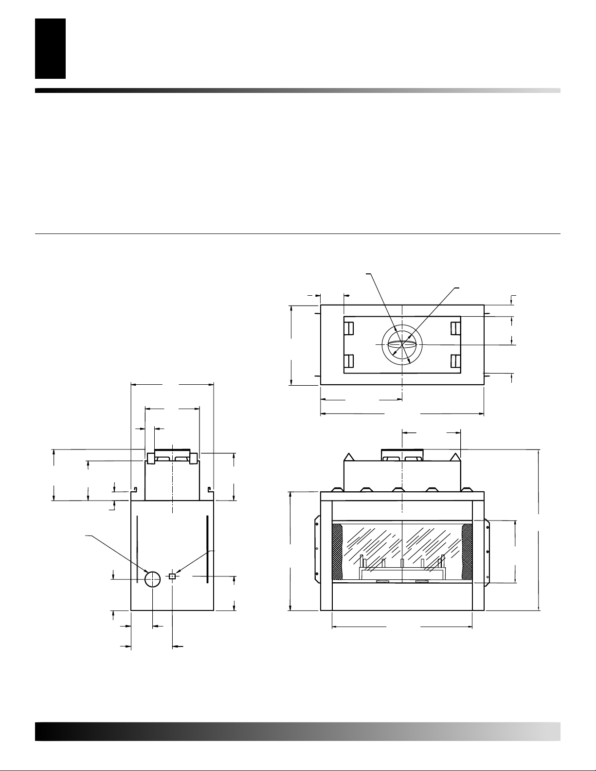
TABLE OF CONTENTS
2
PRODUCT DIMENSIONS
TABLE OF CONTENTS
PRODUCT DIMENSIONS........................................................... 2
INTRODUCTION......................................................................... 3
SAFETY INFORMATION ............................................................ 3
BEFORE YOU BEGIN ................................................................ 3
FIREPLACE INSTALLATION...................................................... 4
OUTSIDE AIR KIT INSTALLATION............................................. 7
GAS LINE INSTALLATION ......................................................... 7
PRODUCT DIMENSIONS
(15.2cm)
(60.9cm)
24"
(60.9cm)
19"
(48.2cm)
1
4
/2"
(11.4cm)
VENTING INSTALLTION ............................................................ 8
OPERATING GUIDELINES AND MAINTENANCE
INSTRUCTIONS ................................................................. 14
TECHNICAL SERVICE ............................................................. 15
REPLACEMENT AND ACCESSORY PAR TS........................... 16
OWNER'S REGISTRATION FORM .......................................... 17
3
/8" Dia.
24"
15
(38.7cm)
6"
O.D.
21
(54.1cm)
5
/16"
Top View
5
42
/8"
(108.2cm)
1
/2"
15
(39.3cm)
10" Dia. I.D.
(25.4cm)
1
9
/2"
(24.1cm)
1
2
/2"
(6.3cm)
17 3/16"
(43.6cm)
12"
(30.4cm)
1
(3.8cm)
1
/2"
Outside Air
1
10
/4"
(26cm)
7"
(177mm)
12"
(304mm)
Left Side View
Figure 1 - Product Dimensions
For more information, visit www.desatech.com
For more information, visit www.desatech.com
17"
(40.6cm)
Gas Line
Conduit
1
11
/4"
(28.5cm)
1
37
/2"
(95.2cm)
1
36
/2"
(92.7cm)
Front View
1
/2"
20
(52cm)
3
52
/4"
(134cm)
55253C

INTRODUCTION
SAFETY INFORMATION
BEFORE YOU BEGIN
3
3
INTRODUCTION
Model V3610ST series is a wood-burning fireplace intended and
approved for installation in either residential homes or buildings of
standard construction. This fireplace system requires the utilization
of a DESA 10" double wall, snap-lock flue pipe system.
GLASS DOORS are optional with this fireplace and come in
different styles. For further details (see page 14).
BE SURE TO CHECK WITH YOUR LOCAL BUILDING
CODES FOR AREA REQUIREMENTS BEFORE INSTALLING THIS FIREPLACE.
SAFETY INFORMATION
IMPORTANT: Read this owner’s manual carefully and
completely before trying to assemble, operate, or service
this fireplace. Improper use of this fireplace can cause
serious injury or death from burns, and fire.
1. This fireplace reaches high temperatures. Keep children and
adults away from hot surfaces to avoid burns or clothing ignition. Fireplace will remain hot for a time after shutdown. Allow surfaces to cool before touching.
2. Carefully supervise young children when they are in the room
with fireplace.
3. Do not modify this fireplace under any circumstances. Any
parts removed for servicing must be replaced prior to operating fireplace.
4. Let fireplace cool before servicing, repairing, or installing accessories. Only a qualified service person should install, service, or repair this fireplace. Have fireplace inspected annually by a qualified service person.
5. Keep the area around your fireplace clear of combustible materials, gasoline, and other flammable vapor and liquids. Do not
operate fireplace where these are used or stored. Do not place
items such as clothing or decorations on or around fireplace.
6. Do not connect this fireplace to a chimney system other than a
DESA chimney system.
7. Due to high temperatures, do not locate this fireplace in high
traffic areas or near furniture and draperies.
8. Provide adequate clearances around air openings into the combustion chamber. NEVER obstruct the front openings of the
fireplace or the flow of combustion and ventilation air. Install
in an area providing ventilation and adequate combustion air.
BEFORE YOU BEGIN
Before beginning the installation of your fireplace, read these
instructions thoroughly. This DESA fireplace and its approved
components are safe when installed according to this installation
manual, and operated as recommended by DESA. Unless you use
DESA approved components tested for this fireplace, YOU MAY
CAUSE A FIRE HAZARD!
The DESA warranty will be voided by, and DESA disclaims any
responsibility for the following actions:
A) Modification of the fireplace or any of the components manufac-
tured by DESA unless otherwise permitted in writing by DESA.
B) The use of a fireplace insert or any component part not ap-
proved by DESA in combination with DESA fireplace.
C) Installation and/or operation in a manner other than instructed
in this manual.
D) The burning of any other fuel not tested or approved by DESA
in this wood burning fireplace.
PROPER INSTALLATION is the most important step in ensuring
a safe and continuous operation of this fireplace. Although grounding may not be required by code in your area, it must be electrically
grounded in accordance with local codes or, in the absence of local
codes, with the National Electrical Code, ANSI/NFPA 70-1990.
This fireplace is intended for installation in accordance with the
National Fire Protection Association Standard for Chimneys, Fireplaces, Vents and Solid-Fuel Burning Fireplaces, NFPA 211, and in
accordance with codes such as the BOCA Basic /National Code, the
Standard Mechanical Code, and the Uniform Building Code.
THIS FIREPLACE IS NOT INTENDED TO BE USED AS
A PRIMARY SOURCE OF HEAT.
NOTE:
installer familiar with the fireplace. The fireplace and chimney
system should be inspected and cleaned before use and periodically
thereafter especially during heating season to prevent the excessive
buildup of soot and creosote and to ensure a safe operating system.
Installation and repair should be done by a qualified
55253C
For more information, visit www.desatech.com
For more information, visit www.desatech.com
FIREPLACE INSTALLATION
4
Selecting Location
Clearances
Mantle Clearances
FIREPLACE INSTALLATION
SELECTING LOCATION
To determine the safest and most efficient location for your fireplace, you must take into consideration the following guidelines:
1. The location must allow for all the proper clearances (see Figure 2).
2. Consider a location where the heat output would not be affected by drafts, air conditioning ducts, windows or doors.
3. A location that avoids the cutting of joists or roof rafters will
make installation easier.
4. If an outside air kit is to be installed, accessibility to outside
combustion air must be considered. This can also be achieved
through a vented crawl space in some cases, for more details
refer to the section on outside air kit installation.
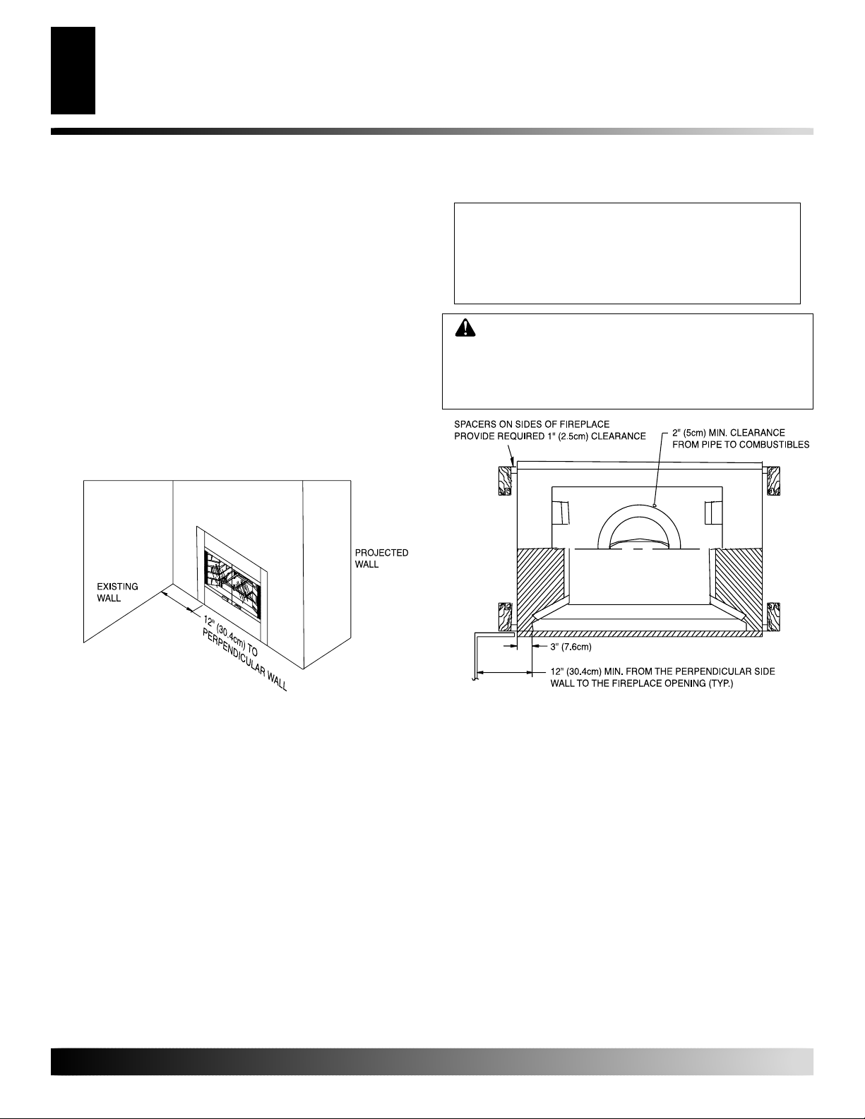
The typical installation for a V3610ST is a projected installation, which
allows you to extend the fireplace any distance into the room. A
projection may be ideal for a new addition on an existing, finished wall.
CLEARANCES
MINIMUM CLEARANCES TO COMBUSTIBLES
Back ............................................. 1" Min.
Adjacent Wall ............................. 12" Min.
Chimney Outer Pipe Surfaces...... 2" Min.
Bottom Of Fireplaces To Floor ..... 0" Min.
CAUTION: Do not block required air spaces with
insulation or any other material. Do not obstruct
effective opening of fireplace with any type of facing
material. Combustible material must not be in contact with the black front face of the fireplace.
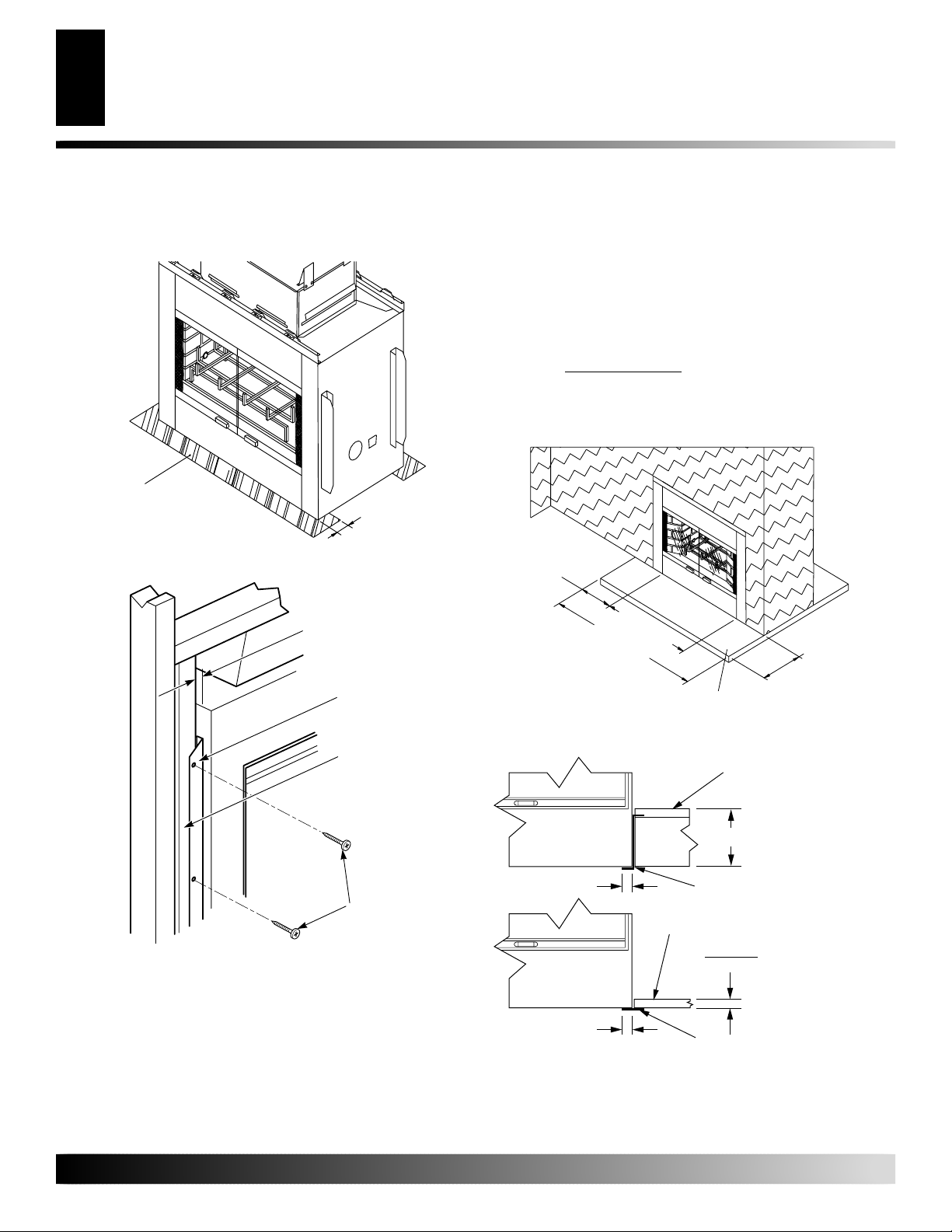
Figure 2 - Plan View of Common Location
For more information, visit www.desatech.com
For more information, visit www.desatech.com
Figure 3 - Fireplace Clearances
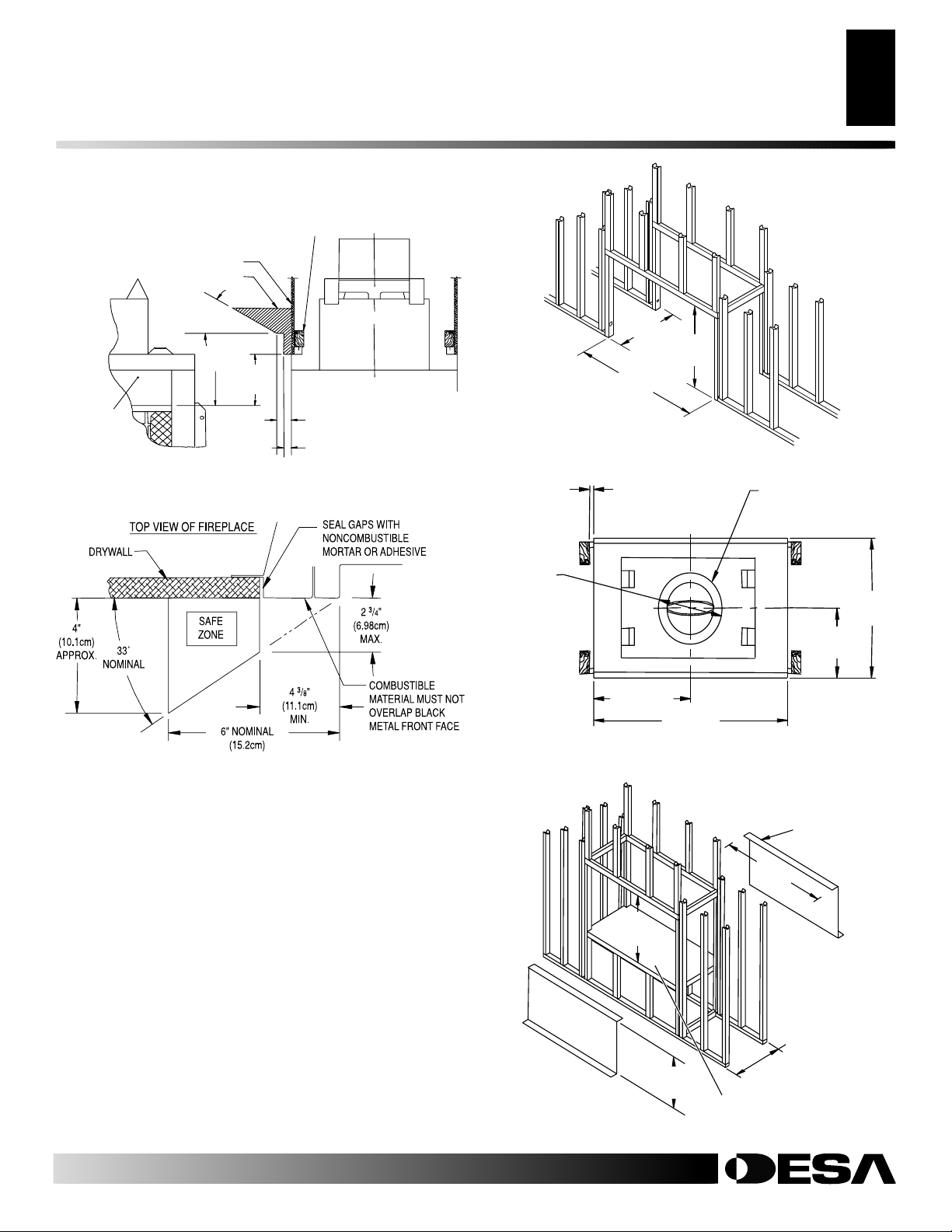
MANTLE CLEARANCES
Woodwork, such as wood trims, mantles, and other combustible
materials, should not be placed within 9 inches of the effective
opening of this fireplace.
Combustible material above and projecting more than 1 1/2 inches
from the fireplace’s front face (see Figure 4, page 5), should not be
placed less than 12 inches from the effective opening of the fireplace
(Ref: NFPA std.7-3.3.3.).
Mantles or any other combustible material may also come up to the
side edge of the black metal face of the fireplace, but only if the
projection from the front face falls within the limits shown in Figure
5, page 5.
55253C
FIREPLACE INSTALLATION
22
3
/
4
"
(57.7cm)
PLATFORM MUST BE
SOLID, FLAT, AND
FULLY SUPPORTED
"Z" TYPE EMBER
PROTECTOR
(NOT SUPPLIED)
A
S
R
E
Q
U
IR
E
D
B
Y
D
E
S
IG
N
A
S
LO
N
G
A
S
C
E
ILIN
G
C
LE
A
R
A
N
C
E
IS
M
A
IN
TA
IN
E
D
4
4
5
/
8
"
(1
1
3
.3
c
m
)
53
7
/
16
"
(135.7cm)
MIN.
Continued
2" X 4" STUD
DRYWALL
COMBUSTIBLE
MATERIALS
33¡
6" NOM.
(15.2cm)
12" MIN.
(30.4cm)
FRONT FACE
FIREPLACE FRONT
VIEW
Figure 4 - Mantel Clearances
9"
(22.8cm)
MIN.
FIREPLACE SIDE
3" NOM.
(7.6cm)
1
/2" MAX.
1
(3.8cm)
VIEW
FIREPLACE INSTALLATION
Mantel Clearances (Cont.)
8
/
5
23
(60cm)
43
1
(109.8cm)
/4"
Figure 6 - Framing Firebox
1" MIN
(2.5cm)
TO COMBUSTIBLES
5
5
Framing
"
39 3/4"
(101cm)
Min.
2" (5cm) MIN.
CLEARANCE
FROM OUTER PIPE
TO COMBUSTIBLES
Figure 5 - Mantel Clearances
FRAMING
If the fireplace is to be installed directly on carpeting, tile (other than
ceramic), or any combustible material other than wood flooring, the
fireplace must be installed upon a metal or wood panel extending the
full width and depth of the fireplace.
Construct framing using dimensions shown in Figures 6, 7, and 8,
depending on your particular installation.
Before securing fireplace to prepared framing, the ember protector
(provided) must be placed between hearth extensions (not supplied), and bottom front edge of the fireplace to protect against
glowing embers (see Figure 9, page 6). If the fireplace is to be
installed on a raised platform, a “Z”-type ember protector (not
supplied) must be fabricated to fit your required platform height (see
Figure 8). The ember protector should be made of 28 gauge
minimum, galvanized sheet metal to prevent corrosion.
3
12
/8" DIA.
15" DIA.
O.D. (31.4cm)
OUTER PIPE
21 5/16"
(54.1cm)
42
(108.2cm)
Figure 7 - Framing Clearances
24"
(60.9cm)
12"
(30.4cm)
5
/8"
55253C
For more information, visit www.desatech.com
For more information, visit www.desatech.com
Figure 8 - Framing Firebox With “Z” Type Ember Protectors
FIREPLACE INSTALLATION
6
Framing (Cont.)
Hearth Extensions
FIREPLACE INSTALLATION
Continued
Secure fireplace to prepared framing at nailing flanges located at the
sides of fireplace as shown in Figure 10.
EMBER
PROTECTOR (TYP. OF 2)
1/2" MAX.
EMBER PROTECTOR
*
STRIPS SUPPLIED
Figure 9 - Ember Protectors
(1.2cm)
If a hearth extensions is to be field constructed, it must be made of
noncombustible inorganic material having and effective thermal
conductivity “K” of 0.84 BTU In/Ft2 Hr.F or least at 1.0 inch
thickness.
Thermal conductivity “K” of materials can be obtained from the
manufacturer or supplier or the noncombustible material.
The minimum required thickness for any material could be obtained
by the following formula:
K factor x 1.0 inch = Thickness required
0.84
If the hearth extension is to be raised, a “Z” type ember protector
must be used (see Figure 8, page 5, and Figure 12).
8" M
IN
(20.3cm
.
)
1/2" (1.27cm)
Minimum To
Combustibles
Nailing
Flanges
Prepared
Framing
Nails or
Screws
Figure 10 - Nailing Flanges
HEARTH EXTENSIONS
A hearth extension is required to protect the combustible floor
surrounding your fireplace. You may obtain kit No. HE-3610ST or
you may fabricate your own per the dimensions shown on Figure 10.
The hearth extension must project a minimum of 16 inches from the
front of the fireplace and a minimum of 8 inches beyond each side
of the fireplace opening (see Figure 11).
36
1
/
2
" M
(92.7cm
52
(133.3cm
IN
1
/
.
2
" M
)
IN
.
)
NONCOMBUSTIBLE
HEARTH EXTENSION
Figure 11 - Hearth Extension
8" Max.
1 1/2" Typ.
“Z” Type Ember Protector
Noncombustible
Hearth Extension
K Factor
1
/2" Typ.
1
Ember Protector
Figure 12 - Raised Hearth Extension
16" M
(40.6cm
Noncombustible
Hearth Extension
.84
For raised
fireplace, see
section on
framing with a
raised platform.
IN.
)
For more information, visit www.desatech.com
For more information, visit www.desatech.com
55253C

OUTSIDE AIR KIT
INSTALLATION
The installation of the outside air kit must be installed during the
rough framing of the fireplace due to the nature of its location.
Outside combustion air can be accessed through an exterior wall or
a vented crawl space (see Figure 13).
CAUTION: Air inlet ducts must not terminate in
attic space.
The maximum height for the air inlet above the platform of fireplace
is a minimum of 3 feet below the chimney cap.
For further details on the installation of the outside air kit, please
refer to the instructions included with the air kit.
Secure Two Collars With
Duct Tape or Screws
Air Inlet
Location
Must Allow
For Bushes
Or Snow
Air Inlet
Termination
OUTSIDE AIR KIT INSTALLATION
GAS LINE INSTALLATION
7
7
FOR UNVENTED ROOM HEATERS, ANSI\IAS\AGA Z21.11.2,
ARE TO BE INSTALLED IN THIS FIREPLACE.
1. To install, remove the knockout indentation on the refractor
(or firebrick) wall located approximately 2 inches above the
refractory hearth floor. The knockout indentation must be firmly
tapped with any solid object until it is released. Remove fragmented portion of refractory (see Figure 14).
2. Remove gas line cover plate on rear of fireplace and pull out insulation from gas line conduit sleeve, save insulation for reuse.
3. Run gas line into the fireplace through the rear at 111/4" from
the floor and through gas line conduit sleeve (if using a raised
platform, add height). Provide sufficient gas line into fireplace
chamber for fitting connection (see Figure 15).
Note:
Secure incoming gas line to wood framing to provide rigidity
for threaded end.
4. Repack insulation around gas line and into sleeves openings.
Seal any gaps between gas line and refractory knockout hole
with refractory cement or commercial furnace cement. Install
the decorative gas appliance or cap off gas line if desired.
Outside of
Fireplace
Gas Line
Conduit
Side Firebrick
Finished Side
Figure 13 - Air Kit Installation
GAS LINE INSTALLATION
WARNING: A qualified service person must con-
nect fireplace to gas supply. Follow all local codes.
NOTICE: BEFORE YOU PROCEED, MAKE SURE
YOUR GAS SUPPLY IS OFF!
A gas line may be installed for the purpose of installing a vented or
vent-free decorative gas appliance available through your local
distributor. Use only gas piping approved by local codes. When
installing a gas line, a shutoff valve designed for installation outside
the appliance is recommended.
The gas pipe is intended for connection to a decorative gas appliances
that operate from natural or propane/LP fuel only: (1), incorporating
an automatic shutoff device and, (2), complying with the Standard for
Decorative Gas Appliances for Installation in Vented Fireplace,
ANSI Z21.60-1990. ONLY UNVENTED GAS LOG SETS WHICH
HAVE BEEN FOUND TO COMPLY WITH THE STANDARD
Remove
Knockout
Remove
Insulation
Temporarily
(Do Not
Discard)
Figure 14 - Removing Knockout for Gas Line Installation
Outside of
Fireplace
Gas Line
Conduit
Repack
Insulation
Figure 15 - Running Gas Line
Replace Screws After
Removing Gas Line
Cover Plate
Incoming
1/2" Black
Iron Pipe
Refractory
Knockout Plug,
Remove by
Tapping Lightly
With A 1/2" Dowel
Side Firebrick
Finished Side
Provide Enough
Threaded End For
Fitting Connection
Seal Opening
With Refractory
Cement
55253C
For more information, visit www.desatech.com
For more information, visit www.desatech.com
GAS LINE INSTALLATION
8
CHIMNEY PIPE INSTALLATION
PIPE INSTALLATION
FIRESTOP SPACERS
GAS LINE INSTALLATION
Continued
WARNING: After ensuring that the gas valve is ON,
test all gas piping and connections for leaks after
installing or servicing. Correct all leaks at once.
WARNING: Never use an open flame to check for
a leak. Apply a noncorrosive leak detection fluid to
all joints. Bubbles forming show a leak. Correct all
leaks at once.
Note:
An appropriate DESA hood (see Replacement and Accessory
Parts, page 16) must be installed when using an unvented gas log set.
CAUTION: When using a decorative appliance,
the damper must be removed or permanently locked
in the open position.
VENTING INSTALLTION
CHIMNEY PIPE INSTALLATION
The DESA chimney system is a snap-lock, double wall pipe. It
consists of a stainless steel inner flue pipe(s), a galvanized outer
pipe, and a wire spacer.
Each section of pipe comes in lengths of 12, 18, 36, and 48 inches,
but the actual lineal gain for each is measured after each section is
fully connected. Lineal gain is the actual measurable length of a part
after two or more parts are connected.
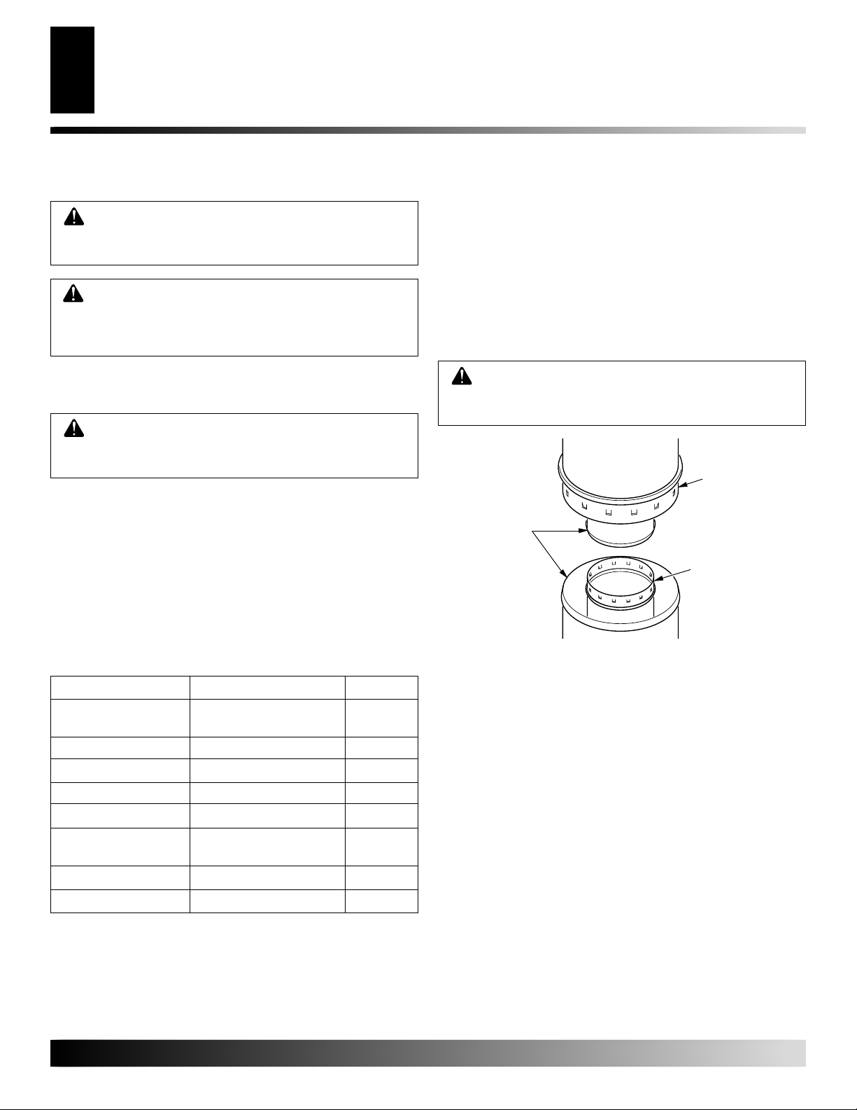
PIPE INSTALLATION
Place pipe assembly (inner and outer with wire spacer) over starter
collar. Inner pipe(s) fit inside inner pipe(s). Outer pipe fits outside
outer pipe.
Begin by aligning hemmed end of inner flue pipe into the inner starting
flue pipe of fireplace. Push down until hem “snap-locks” with lances. The
outer pipe is just the opposite, the female end has the lances. Continue the
same procedure for the outer pipe (see Figure 16). It is important to assure
the joints between the chimney sections are fully locked. Check by pulling
chimney upward after locking pipe hem(s). The chimney should not
come apart if properly locked. It is not necessary to add screws to keep
vertical or angled chimney runs together.
WARNING: The opening around the starter collar on
top of the fireplace must never be obstructed. Never use
blown insulation to fill the chimney enclosure.
15" (35.1cm)
Galvanized
Outer Pipe
Hemmed
Ends
10" (25.4cm)
Stainless Inner
Pipe Lanced
Side Up
Figure 16 - Pipe Connection
MODEL NO. DESCRIPTION GAIN
V3610ST See-Through" 52 3/4"
Fireplace
48-10DM/48-10TM Flue Pipe 46 5/8"
36-10DM/48-10TM Flue Pipe 34 5/8"
18-10DM/48-10TM Flue Pipe 16 5/8"
12-10DM/48-10TM Flue Pipe 10 5/8"
ETL-10DM Chase Style 1" to 12"
Termination
RTT-10 Round Top Termination 6"
RTL-10DM Round Top Termination 7"
For more information, visit www.desatech.com
For more information, visit www.desatech.com
FIRESTOP SPACERS
Firestop spacers are required at each point where the chimney
penetrates a floor or ceiling joist space. Their purpose is twofold.
They establish and maintain the required clearance between the
outer pipe and combustible materials, they also serve as a shield
between floors as required by most codes.
When penetrating a floor or ceiling at an angle, use firestop spacer
number 30 FS-10DM (see Replacement and Accessory Parts,
back page).
When the pipe passes through a framed opening into a living space
above, a firestop must be placed on the ceiling below (see Figure 17,
page 9). When the pipe passes through a framed opening into an attic
space above, a firestop must be placed on the attic floor above (see
Figure 18, page 9).
55253C

VENTING INSTALLTION
Continued
Living Space Above Ceiling
Existing Ceiling
Frame
Firestop Spacer
Screw (8)
FIRESTOP SPACERS
ELBOW OFFSET INSTALLATION
SUPPORT SECTIONS
9
9
SUPPORT SECTIONS
The chimney support section is a 4-inch strap and 12 inch length of pipe.
A chimney support is required every 30 feet above the fireplace after a
straight chimney run, or above a return elbow after a straight chimney
run (see Figure 20). This support is designed to relieve the extra weight
load on the fireplace and elbows when high chimneys are installed.
To achieve desired offset, you may install combinations of 12, 18,
36, and 48 inch lengths of double wall pipe. See Figure 21 and Rise
and Offset Chart below.
2" (5.1cm)
Minimum
Figure 17 - Firestop Spacer For Living Space
Screw (8)
Attic Space
Above Ceiling
Figure 18 - Firestop Spacer for Attic Space
Firestop Spacer
Existing Ceiling
Frame
ELBOW OFFSET INSTALLATION
Chimney weight above offset rests on return elbow. Straps must be
secured with nails to rafters or joists (see Figure 19).
Strap
Figure 19 - Elbow Offset
12S-10DM
Support
Required
30 FT.
(9.14m)
30 FT.
(9.14m)
Return
Elbow
Angled Firestop
Ceiling Support
Straps
Return
Elbow
Figure 20 - Chimney Supports
Figure 21 - Rise and Offset
A
RISE AND OFFSET CHART
A B Length of Pipe
(Offset) (Rise) 48 36 18 12
4 3/8 16 3/8 Elbow Set Only
9 1/2 25 1/4 1
12 1/2 30 3/8 1
14 3/8 34 2
17 5/8 39 1/4 11
21 1/2 46 1
22 3/4 48 1/8 12
26 3/8 54 7/8 1
26 3/8 60 1 1
31 3/4 63 3/4 11
34 3/4 69 1 1
38 5/8 75 5/8 2
39 7/8 77 7/8 111
43 3/4 84 1/2 11
46 3/4 87 3/4 21
48 7/8 93 3/8 2
B
55253C
For more information, visit www.desatech.com
For more information, visit www.desatech.com

SUPPORT SECTIONS
10
FINISHING YOUR CHIMNEY SYSTEM
10 Foot Rule
Minimum Chimney Height
Maximum Chimney Height
VENTING INSTALLTION
Continued
Maximum length of pipe between supports is 6 feet of angled run.
A maximum of two 6 foot angled run sections per chimney system
(See Figure 22).
RETURN
RETURN
ELBOW
OFFSET
ELBOW
6’ MAX
(15.2cm)
OFFSET
ELBOW
RETURN
ELBOW
6’ MAX
(15.2cm)
CEILING
SUPPORT
PIPE
V12S-8DM
6’ MAX
(15.2cm)
6’ MAX
(15.2cm)
ELBOW
6’ MAX
(15.2cm)
OFFSET
ELBOW
RETURN
ELBOW
6’ MAX
(15.2cm)
FINISHING YOUR CHIMNEY SYSTEM
10 Foot Rule
All chimney terminations must extend a minimum of 3 feet above
the highest point where it passes through the roof, and must be at
least 2 feet above the roof within a 10 foot horizontal span (see
Figure 23).
IMPORTANT:
above the roof line, use support wires to keep chimney secure. The
support wires may be attached to the outer pipe of the chimney with
screws, provided the screws do not penetrate the inner flue pipe.
Figure 23 - 10 Foot Rule
If an exposed portion of chimney is greater than 4 feet
Figure 22 - Typical Offset Installations
Minimum Chimney Height
The minimum chimney height (measured from bottom of fireplace to
flue gas outlet-end of pipe) is 16 feet for a straight run, 16 feet minimum
for a run with 1 elbow set, and 25 feet minimum for a run with 2 elbow
sets. (A set consists of one starter elbow and one return elbow.)
Uncommon circumstances such as neighboring hills, tall trees, or
strong wind areas can cause down drafts in the chimney system. In
such cases going beyond the minimum recommended height would
be preferable to provide a better draw.
Maximum Chimney Height
The fireplace height approved for any chimney run with this
fireplace system is 40 feet measured from bottom of fireplace to flue
outlet-end of pipe. See Figure 24, page 11
For more information, visit www.desatech.com
For more information, visit www.desatech.com
55253C

VENTING INSTALLTION
Continued
WARNING: Do not operate an unvented gas log
set in this fireplace with the chimney removed.
RTL-10DM RTL-10DM ETL-10DM
Storm
Collar
Flashing
MINIMUM
Firestop
Spacer
HEIGHT
15 FT.
(4.5m)
MAXIMUM
HEIGHT
CHASE
TERMINATION
40 FT.
(12m)
FINISHING YOUR CHIMNEY SYSTEM
Maximum Chimney Height (Cont.)
Chimney Maintenance
11
11
Chimney Maintenance
Have your chimney system cleaned and inspected regularly to
ensure safe and efficient operation.
Using Figure 24 and the roof opening chart below, determine the
opening that will be required for the pitch of your particular roof.
Roof Opening Chart
PITCH Opening “A” Use Flashing
(degrees) Max. (inches) Model Number
FLAT 19 6F-10
0-6/12 23 1/4 6F-10
(26.6 deg. Slope)
6/12-12/12 30 3/4 12F-10
(56.3 deg. Slope)
12/12/-18/12 40 1/8 18F-10
(56.3 deg. Slope)
19" Min.
(48.26cm)
2" Min.
(5.08cm)
30" Min.
(76.2cm)
Firestop
Spacer
30°
Firestop
Spacer
30° Offset/
Return
Figure 24 - Maximum Chimney Height
2" Min.
(5.08cm)
2" Min.
(5.08cm)
Opening
A
Figure 25 - Roof Opening
Before cutting hole, temporarily remove shingles around area to be
opened. After preparing the opening on the roof, continue to add
sections of pipe until it extends a minimum of 30 inches above
highest point of roof cutout (see Figure 25).
With the termination, the minimum height should add up to 3 feet
(see 10-Foot Rule and Figure 22, page 10).
55253C
For more information, visit www.desatech.com
For more information, visit www.desatech.com

FINISHING YOUR CHIMNEY SYSTEM
12
Flashing Installation
Storm Collar Installation
Terminations
VENTING INSTALLTION
Continued
Flashing Installation
Determine the flashing to be used with the roof opening chart, page
11. Slide flashing over pipe until base is flat against roof. Replace
as many shingles as needed to cover exposed area and flashing base.
Secure in position by nailing through shingles.
THROUGH FLASHING CONE.
Storm Collar
Flashing
Nail Only Outer
Perimeter of
Flashing
Underlap Shingles
At Bottom
Figure 26 - Flashing Installation
DO NOT NAIL
Chimney Pipe
Overlap
Shingles
Top and
Sides
Only
Storm Collar Installation
Place storm collar over pipe and slide down until snug against the
open edge of the flashing (see Figures 26 and 27). Apply waterproof
caulking to all seams and notches around storm collar and also at
base around shingles.
Terminations
The fireplace system must be terminated with the listed round top or
chase terminations. In any case, refer to the installation instructions
supplied with the terminations.
The terminations approved for this fireplace are RTL-10DM,
which can be used for flashing, or chase and ETL-10DM for
chase style termination only. Figure 28 shows an RTL-10DM
round top termination.
CAUTION: Do not seal openings on the rooftop
flashing. Follow the installation instructions provided with the termination being used.
Stainless
Inner Flue
Pipe
Secure
Termination
To Outer
Pipe With
3 Screws
Overlap Shingles
(Top and Sides)
of Flashing Base
RTL-10DM
1" Noncombustible
Spacer
Chase Top
Screen
1" Space
Apply Waterproof
Caulking
Storm Collar
Flashing
Underlap
Shingles
Chimney Pipe
Storm Collar
Figure 27 - Storm Collar
Caulk
Figure 28 - Terminations
Flashing
For more information, visit www.desatech.com
For more information, visit www.desatech.com
55253C

VENTING INSTALLTION
Continued
FINISHING YOUR CHIMNEY SYSTEM
Chase Installation
Installing Fireplace Facing
13
13
Chase Installation
Instructions for chase installations are included with the chase style
termination chosen. However, it is worthy to mention here that in a
multiple chase installation, provide adequate distance between
terminations, or smoke spillage from one termination to another
may occur. We suggest terminations be separated at least 30 inches
center to center, and stacked at a vertical height difference of 18
inches vertically from one termination to the other (see Figure 29).
18" MIN. TYP.
30" MIN.
30" MIN.
Figure 29 - Chase Clearances
INSTALLING FIREPLACE FACING
Any noncombustible material may be used for facing (glass, tile,
brick, etc.) as long as the proper clearances are adhered to and the
fireplace openings are not obstructed in any way. Refer to Clearances,
page 5, and Figure 30).
Use only heat resistant, noncombustible mortar or adhesive when
securing facing material to the front of the fireplace. When placing
facing at the upper edge of the effective opening of the fireplace, provide
an “L” shaped piece of metal, extending the full width of the opening.
Secure with sheet metal screws at a distance high enough from the
edge as to not interfere with the operation of doors. This assures that
the facing material, in time, should not block the opening if it where
to lose cohesion.
Noncombustible
Facing Material
Do Not
Block
Effective
“L” Shaped
Metal Support
Opening
55253C
Noncombustible
Facing Material
Figure 30 - Fireplace Facing (your fireplace may vary from
illustration)
For more information, visit www.desatech.com
For more information, visit www.desatech.com

OPERATING GUIDELINE AND MAINTENANCE INSTRUCTIONS
14
Glass Doors
OPERATING GUIDELINES
AND MAINTENANCE
INSTRUCTIONS
GLASS DOORS
Glass doors are optional with the V3610ST fireplace. Glass doors
come in cabinet type and BI-fold type. Check with your local
distributor for availability and options.
To install glass doors, refer to the installation instructions that are
included with the glass door kit.
When the fireplace is in operation, all doors must be in the FULLY
OPEN or FULLY CLOSED position only or a fire hazard may be
created (see Figure 31 and 32).
A fireplace equipped with glass doors operates much differently
than a fireplace with an open front. A fireplace with glass doors has
a limited amount of air for combustion. Excessive heat within the
fireplace can result if too large a fire is built or if the combustion air
gate is not completely open.
The following tips should be followed to assure that both the fireplace
and the glass door retain their beauty and function properly.
• Both flue damper and the glass doors must be fully open before
starting the fire. This will provide sufficient combustion air and
maintain safe temperatures in the firebox. If operating with glass
doors closed, do so at this time. Do not operate with doors partially open. Doors must be fully open or fully closed.
• The glass must be allowed to warm slowly and evenly . The tempered glass will withstand a gradual temperature rise to 550 degrees Fahrenheit, which is more than other such materials as
pitch laden logs, very dry mill end lumber, large amounts of
paper or cardboard boxes.
• Always keep the fire well back from the doors and never allow
flames to contact the glass.
FULLY CLOSED
FIREPLACE FRONT
FULLY OPEN
FIREPLACE FRONT
Figure 31 - Bi-Fold Glass Doors (Top View)
Side
Panel Is
Stationary
WARNING: Fireplaces equipped with glass doors
should be operated only with the doors fully open or
fully closed. Doors left partly open may draw gas (if
used) and flame out of the fireplace opening, creating
risk of both fire and smoke.
Cleaning the Glass
Clean glass with any commercial glass cleaner or soap and water.
DO NOT use any abrasive material to clean glass. DO NOT clean
glass with cool water if the glass is still too hot from the fire. To
remove doors, refer to instructions included with glass door kit.
For more information, visit www.desatech.com
For more information, visit www.desatech.com
Glass Cabinet Doors
Operate Fully Open, or Fully
Closed ONLY
Figure 32 - Cabinet Door Operation
55253C

OPERATING GUIDELINE AND MAINTENANCE INSTRUCTIONS
OPERATING GUIDELINES
AND MAINTENANCE
INSTRUCTIONS
Continued
Damper Mechanism
Outside Air Mechanism
Grate
TECHNICAL SERVICE
15
15
DAMPER MECHANISM
The damper control lever is located inside the fire chamber (see
Figure 33). Make sure lever is cool before handling. Pull down to
CLOSE, push up to OPEN. The damper must be open when lighting
a fire. Not doing so will cause smoke spillage into the room. When
the fireplace is not in use, close the damper to prevent down drafts
to enter the room.
GRATE
OUTSIDE AIR
HANDLE
DAMPER CONTROL LEVER
PULL DOWN TO CLOSE
PUSH UP TO OPEN
Figure 33 - Damper Operation
PULL TO CLOSE
PUSH TO OPEN
OUTSIDE AIR MECHANISM
The outside air handle is located at the right hand side of the fireplace
rear refractory (see Figure 33). Pull to close, push to open. Always
open the mechanism when starting a fire. This provides adequate
outside combustion air. Close the mechanism when not in use to
prevent cold air from entering the room. Periodically check you’re
outside air intake vent hood for any possible obstructions such as
snow, bushes, etc.
GRATE
The grate is designed to provide you with the maximum solid fuel
capacity. Do not attempt to defeat its purpose. Doing so may cause
smoke spillage and a fire hazard. Do not overload the grate or
obstruct the required air space beneath it. Always keep ashes from
building up under the grate.
WARNING: RISK OF FIRE! Replace grate with
DESA model 3610ST-GR grate only.
Never obstruct the flow of combustion and ventilation air. Keep the
front of the fireplace clear of all obstacles and materials.
WARNING: Children and adults should be alerted
to the hazards of high surface temperatures, and to
stay away to avoid burns or clothing ignition. Young
children should be carefully supervised when they
are in the same room as the fireplace.
For further operating guidelines, instructions, and warranty information not contained in this owner’s manual, contact your authorized dealer.
TECHNICAL SERVICE
You may have further questions about installation, operation, or
troubleshooting. If so, contact DESA’s Technical Service Department at 1-866-672-6040. When calling please have your model and
serial numbers of your heater ready.
You can also visit DESA’s technical services web site at
www.desatech.com.
55253C
For more information, visit www.desatech.com
For more information, visit www.desatech.com

REPLACEMENT AND ACCESSORY PARTS
16
REPLACEMENT AND ACCESSORY PARTS
When ordering replacement or accessory items, please have your fireplace’s model name and number and the part number of the item(s)
you are ordering ready. The model name or number of your fireplace may be found on the rating plate located inside the fireplace.
Refer to the parts list and diagrams when ordering replacement parts for your fireplace.
Repair parts or accessory items may be bought from your distributor/dealer or directly from DESA. You can call 1-866-672-6040.
All product specifications are subject to change without notice.
IMPORTANT:
Use of any other glass door assembly not tested with this fireplace may constitute a fire hazard and will void the DESA warranty.
Storm
Collar
Storm
Collar
Double Wall Chimney Pipe(s) And Accessories Are Also Available In Triple Wall
Storm Collar
SC-10
Flashing
6F-10DM
12F-10DM
18F-10DM
24F-10DM
Roof Pitch
0 to 6/12
6/12 to 12/12
12/12 to 18/12
18/12 to 24/12
Comes With
Wire Spacer
Double Wall
Chimney Pipe
12-10DM (12" Long)
18-10DM (18" Long)
36-10DM (36" Long)
48-10DM (48" Long)
Chimney pipe assy.
(includes outer and
inner pipes)
Round Top Termination
RTL-10DM
Starter
Elbow
OUTSIDE AIR KIT
AK-4
Return
Elbow
Econo Top Termination
ETL-10DM
Black - 01244
Brass - 01245
Chrome - 01246
Double Wall
PIpe Support Assembly
12S-10DM
Bi-Fold Door Set
GLASS DOORS
Adjustable Hood
10" Grate
11169
HEARTH
EXTENSION
KIT
HE-3610ST
Vent
Hood
Vent
Plaster
Collar
16"
1
52
/2"
For more information, visit www.desatech.com
For more information, visit www.desatech.com
Connector Duct - 4"x 3’
Hearth
Extensions
(2)
Ember
Protectors (2)
Hood Assembly
AK-V
Cabinet Door Set
55253C

OWNER'S REGISTRATION FORM
In order to provide better customer service for this and future purchases, we recommend that you register your product with us.
You can register online at www.desatech.com. If access to our website is not available to you, please complete this Owner’s
Registration Form and mail to the address on the back of this owner’s manual. Please provide the following product information:
Brand:
Model:
Date Purchased:
Serial Number:
First Name: Last Name:
Address:
City: State: Zip: Country:
Home Phone: ( ) -
E-Mail:
Please answer the following questions to register your product with DESA:
1. Where will the product be used?
❍ Living/Family Room ❍ Office/Warehouse ❍ Utility Shed/Outbuilding ❍ Garage ❍ Bedroom ❍ Bathroom ❍ Other
2. If you bought this product yourself, did you plan to purchase this type of product before going into the store? ❍ Yes ❍ No
3. Who selected the product? ❍ Male ❍ Female ❍ Both
4. What is the population of your area? ❍ Under 10,000 ❍ 10,000 to 25,000 ❍ 25,000 to 50,000 ❍ 50,000 to 100,000
❍ 100,000 to 250,000 ❍ Over 250,000
5. What is your primary source of heat? ❍ Propane (LP Gas) ❍ Fuel Oil ❍ Wood ❍ Natural Gas ❍ Electric ❍ Other
6. How was the product installed? ❍ Professional Installer ❍ Self ❍ Other
7. Cost of product excluding sales tax? $___________________
8. Cost to install product? $____________________
9. Type of store where product was purchased? ❍ Hardware ❍ Propane Dealer ❍ Natural Gas/Utility Co. ❍ Home Center/Builder’s Supply
❍ Fireplace or Hearth Shop ❍ Farm Store ❍ Other
10. What motivated you to buy this product? ❍ Sudden Cold Weather ❍ Replace Older Model ❍ D.I.Y. Home Project
❍ Emergency Back-Up Heat ❍ Heater was on Sale ❍ Energy Savings/High Efficiency ❍ Construction Project ❍ Other
11. How did you learn about this product brand? ❍ Advertising ❍ Relative or Friend ❍ Store Display ❍ Other ________________________
12. Level of Education of Purchaser: ❍ Some High School ❍ Completed High School ❍ Completed College ❍ Completed Graduate School
13. Age of Purchaser: ❍ Under 20 ❍ 20 - 29 ❍ 30 - 39 ❍ 40 - 49 ❍ 50 - 59 ❍ 60 or Over
14. Buyer’s total annual household income: ❍ Under $15,000 ❍ $15,000 to $19,999 ❍ $20,000 to $34,999 ❍ $35,000 to $49,999
❍ $50,000 to $74,999 ❍ $75,000 to $99,999 ❍ $100,000 and Over
15. Store where product was purchased:
Name: ______________________________________
City: _______________________ State: __________
16. In choosing this product, how important were the following:
Availability
Price
Brand Name
Overall Quality
Heat Output
Made in USA
Warranty
Local Service
Value for Price
Prior Brand Experience
Controls Location
Thermostat, Remote, or Manual Operation
Ease of Operation
Special Features
Salesperson’s Recommendation
Friend/Relative’s Recommendation
Portability
Quiet Operation
55253C
For more information, visit www.desatech.com
For more information, visit www.desatech.com
Not Important Somewhat Important Very Important
(Comfort Glow, Vanguard, etc.)
(EFP33PR, VTGH33NR, etc.)
Note:
Keep receipt for warranty verification.
7 or 9 digit number located on product or identification tag.
❍
❍
❍
❍
❍
❍
❍
❍
❍
❍
❍
❍
❍
❍
❍
❍
❍
❍
❍
❍
❍
❍
❍
❍
❍
❍
❍
❍
❍
❍
❍
❍
❍
❍
❍
❍
❍
❍
❍
❍
❍
❍
❍
❍
❍
❍
❍
❍
❍
❍
❍
❍
❍
❍
17
17

18
TAPE
2701 Industrial Drive
P.O. Box 90004
Bowling Green, KY 42102-9004
Postage
Required
For more information, visit www.desatech.com
For more information, visit www.desatech.com
TAPE
55253C

NOTES
_______________________________________________________________________________________________
_______________________________________________________________________________________________
_______________________________________________________________________________________________
_______________________________________________________________________________________________
_______________________________________________________________________________________________
_______________________________________________________________________________________________
_______________________________________________________________________________________________
_______________________________________________________________________________________________
_______________________________________________________________________________________________
_______________________________________________________________________________________________
_______________________________________________________________________________________________
19
19
_______________________________________________________________________________________________
_______________________________________________________________________________________________
_______________________________________________________________________________________________
_______________________________________________________________________________________________
_______________________________________________________________________________________________
_______________________________________________________________________________________________
_______________________________________________________________________________________________
_______________________________________________________________________________________________
_______________________________________________________________________________________________
_______________________________________________________________________________________________
_______________________________________________________________________________________________
_______________________________________________________________________________________________
_______________________________________________________________________________________________
_______________________________________________________________________________________________
_______________________________________________________________________________________________
_______________________________________________________________________________________________
_______________________________________________________________________________________________
_______________________________________________________________________________________________
_______________________________________________________________________________________________
_______________________________________________________________________________________________
_______________________________________________________________________________________________
_______________________________________________________________________________________________
_______________________________________________________________________________________________
For more information, visit www.desatech.com
For more information, visit www.desatech.com
55253C

20
2701 Industrial Drive
P.O. Box 90004
Bowling Green, KY 42102-9004
55253
NOT A UPC
For more information, visit www.desatech.com
For more information, visit www.desatech.com
55253
Rev. C
03/03
55253C
 Loading...