

Desa BLP55VA, REM55PVA, TB115A, RLP55VA, 85-FACA Owner's Manual
...
PROPANE CONSTRUCTION FORCED AIR HEATER
OWNER’S MANUAL
VARIABLE 30-55,000, 50-85,000 AND 75-125,000 BTU/HR
IMPORTANT: Read and understand this manual before
assembling, starting or servicing heater. Improper use
of heater can cause serious injury. Keep this manual for
future reference.
GENERAL HAZARD WARNING:
Failure to comply with the precautions and instructions
provided with this heater, can result in death, serious
bodily injury and property loss or damage from hazards
of re, explosion, burn, asphyxiation, carbon monoxide
poisoning and/or electrical shock.
Only persons who can understand and follow the in-
structions should use or service this heater.
If you need assistance or heater information such as an in-
structions manual, labels, etc. Contact the manufacturer.
Safety .................................................................. 2
Product Identication ........................................... 3
Unpacking............................................................ 3
Theory of Operation............................................. 4
Propane Supply ................................................... 4
Installation ........................................................... 5
Ventilation ............................................................ 5
Operation ............................................................. 6
Storage ................................................................ 6
TABLE OF CONTENTS
Maintenance ........................................................ 7
Troubleshooting ................................................... 7
Service Procedures ............................................. 8
Specications .................................................... 10
Wiring Diagram .................................................. 10
Replacement Parts .............................................11
Technical Service................................................11
Parts .................................................................. 12
Warranty ............................................................ 18
Save this manual for future reference.
For more information, visit www.desatech.com
SAFETY
WARNING: This product
contains and/or generates
chemicals known to the State
of California to cause cancer or
birth defects or other reproductive harm.
WARNING: Fire, burn, inhala-
tion and explosion hazard. Keep
solid combustibles, such as building materials, paper or cardboard,
a safe distance away from the
heater as recommended by the
instructions. Never use the heater
in spaces which do or may contain
volatile or airborne combustibles
or products such as gasoline, solvents, paint thinner, dust particles
or unknown chemicals.
WARNING: Not for home or
recreational vehicle use.
The heater is designed for use as a construction heater in accordance with ANSI Z83.7/
CGA2.14. Other standards govern the use of
fuel gases and heating products for specic
uses. Your local authority can advise you
about these. The primary purpose of construction heaters is to provide temporary heating
of buildings under construction, alteration or
repair. Properly used, the heater provides safe
economical heating. Products of combustion
are vented into the area being heated.
We cannot foresee every use which may be
made of our heaters. Check with your local
re safety authority if you have questions
about heater use.
Carbon Monoxide Poisoning: Some people
are more affected by carbon monoxide than
others. Early signs of carbon monoxide poisoning resemble the u, with headaches, dizziness and/or nausea. If you have these signs,
the heater may not be working properly. Get
fresh air at once! Check for proper ventilation
and have heater serviced.
Propane Gas: Propane gas is odorless. An
odor-making agent is added to propane gas.
The odor helps you detect a propane gas
leak. However, the odor added to propane
gas can fade. Propane gas may be present
even though no odor exists.
Make certain you read and understand all
warnings. Keep this manual for reference. It
is your guide to safe and proper operation of
this heater.
1. Install and use heater with care. Follow all
local ordinances and codes. In the absence
of local ordinances and codes, refer to the
Standard for Storage and Handling of Lique-
ed Petroleum Gas, ANSI/NFPA 58 and the
Propane Gas Installation Code, CAN/CGA
B149.2. This instructs on the safe storage
and handling of propane gases.
State of Massachusetts: The installation
must be made by a licensed plumber or
gas fitter in the Commonwealth of Massachusetts.
2. Use only the electrical voltage and fre-
quency specied on model plate. The
electrical connections and grounding of
the heater shall follow the National Electric
Code, ANSI/NFPA 70 or the Canadian
Electrical Code, Part 1.
3. Electrical Grounding Instructions - This
appliance is equipped with a three-prong
(grounding) plug for your protection against
shock hazard and should be plugged directly into a properly grounded three-prong
receptacle or extension cord.
4. Use only the hose and factory preset
regulator provided with the heater.
5. Use only propane gas set up for vapor
withdrawal.
6. Provide adequate ventilation. Before using heater, provide at least a three square
foot opening of fresh, outside air for each
100,000 Btu/Hr (105,500 k/j) of rating.
7. For indoor use only. Do not use heater
outdoors.
8. Do not use heater in occupied dwellings
or in living or sleeping quarters.
9. Do not use heater in a basement or below
ground level. Propane gas is heavier than
air. If a leak occurs, propane gas will sink
to the lowest possible level.
10. Keep appliance area clear and free from
combustible materials, gasoline, paint
thinner and other ammable vapors and
liquids. Dust is combustible. Do not use
heater in areas with high dust content.
www.desatech.com
121231-01B2
SAFETY
Continued
11. Minimum heater clearances from combustible materials:
Outlet: 8 Ft. (2.4 m), Sides: 2 Ft. (0.6 m),
Top: 6 Ft. (1.8 m), Rear: 2 Ft. (0.6 m)
12. Keep heater at least 6 feet from propane
tank(s). Do not point heater at propane
tank(s) within 20 feet (6.1 m).
13. Keep propane tank(s) below 100 ° F
(37.8° C).
14. Check heater for damage before each
use. Do not use a damaged heater.
15. Check hose before each use of heater.
If highly worn or cut, replace with hose
specied by manufacturer before using
heater.
16. Locate heater on stable and level surface
if heater is hot or operating.
17. Never block air inlet (rear) or air outlet
(front) of heater.
18. Keep heater away from strong drafts,
wind, water spray, rain or dripping water.
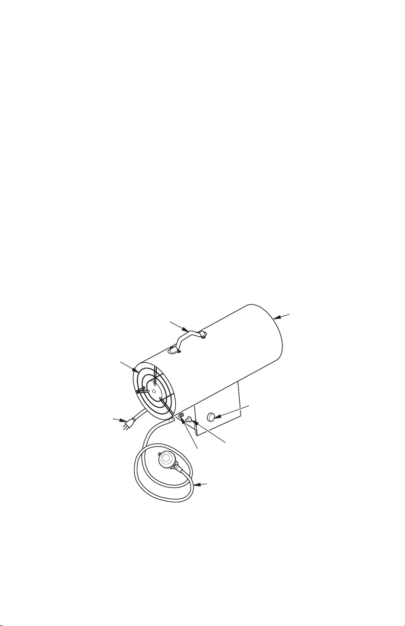
PRODUCT IDENTIFICATION
19. Do not leave heater unattended.
20. Keep children and animals away from
heater.
21. Never move, handle or service a hot
or operating heater. Severe burns may
result. You must wait 15 minutes after
turning heater off.
22. To prevent injury, wear gloves when handling heater.
23. Never attach duct work to heater.
24. Do not alter heater. Keep heater in its
original state.
25. Do not use heater if altered.
26. Turn off propane supply to heater and
unplug heater when not in use.
27. Use only original replacement parts. This
heater must use design-specic parts.
Do not substitute or use generic parts.
Improper replacement parts could cause
serious or fatal injuries.
Handle
Fan
Guard
Variable Heat
Output Control
Power Cord
Inlet
Connector
Hose/Regulator
Assembly
Figure 1 - Variable 75-125,000 Btu/Hr (Heater may vary from illustration)
Knob
Fuel Valve Button
Hot Air Outlet
(Front)
UNPACKING
1. Remove all packing items applied to
heater for shipment. Keep plastic cover
caps (attached to inlet connector and
hose/regulator assembly) for storage.
121231-01B 3
www.desatech.com
2. Remove all items from carton.
3. Check heater for any shipping damage. If
heater is damaged call DESA Heating, LLC
at 1-866-672-6040 for replacement parts
before returning to dealer.
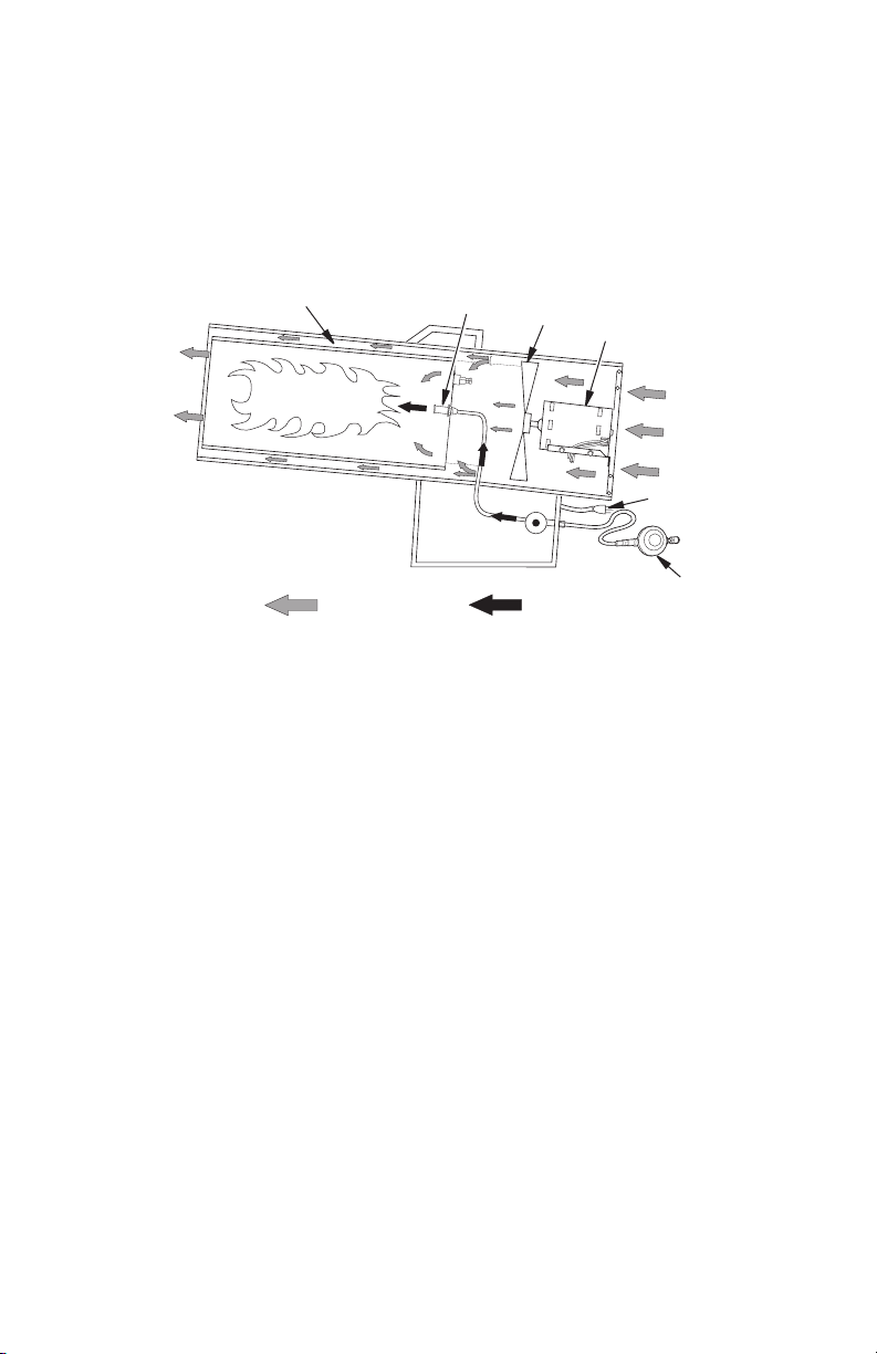
THEORY OF OPERATION
Air For Combustion
And Heating
Fuel
The Fuel System: The hose/regulator assembly attaches to the propane gas supply. The
propane gas moves through the automatic
control valve and out the nozzle.
The Air System: The motor turns the fan. The
fan pushes air into and around the combustion
chamber. This air is heated and provides a
stream of clean, hot air.
Combustion Chamber
Clean
Heated
Air Out
(Front)
Figure 2 - Cross Section Operational View (Heater may vary from illustration)
The Ignition System: The spark transformer
and spark plug lights the main burner
The Safety Control System: This system
causes the heater to shut down if the ame
goes out.
Note: Some parts are located differently on
some models.
Nozzle
Fan
Motor
Power Cord
Hose/Regulator
Assembly
PROPANE SUPPLY
Propane gas and propane tank(s) are to be
furnished by the user.
Use this heater only with a propane vapor
withdrawal supply system. See Chapter 5
of the Standard for Storage and Handling of
Liqueed Petroleum Gas, ANSI/NFPA 58.
Your local library or re department will have
this booklet.
The amount of propane gas ready for use
from propane tanks varies. Two factors decide
this amount:
1. The amount of propane gas in tank(s)
2. The temperature of tank(s)
The following chart shows the number of 100 lb
(45 kg) tanks needed to run this heater.
Number of tanks
Temperature Models
at tank location 55 85 125
above 20° F (-7° C) 1 1 2
20° F (-7° C) to -0 (-18° C)
1 2 3
below -0° F (-18° C) 2 2 (Use larger
tank)
Smaller tanks can be used for limited run
times but it is recommended to use larger
tanks for optimum performance.
Less gas is vaporized at lower temperatures.
You may need two or more 100 pound (45
kg) tanks or one larger tank in colder weather.
Your local propane gas dealer will help you
select the proper supply system. The minimum
surrounding-air temperature rating for each
heater is -20° F (-29° C).
Cool
Air In
(Back)
www.desatech.com
121231-01B4
INSTALLATION
WARNING: Review and understand the warnings in the
Safety section, page 2. They are
needed to safely operate this
heater. Follow all local codes
when using this heater.
WARNING: Test all gas piping
and connections for leaks after
installing or servicing. Never use
an open ame to check for a leak.
Apply a mixture of liquid soap
and water to all joints. Bubbles
forming show a leak. Correct all
leaks at once.
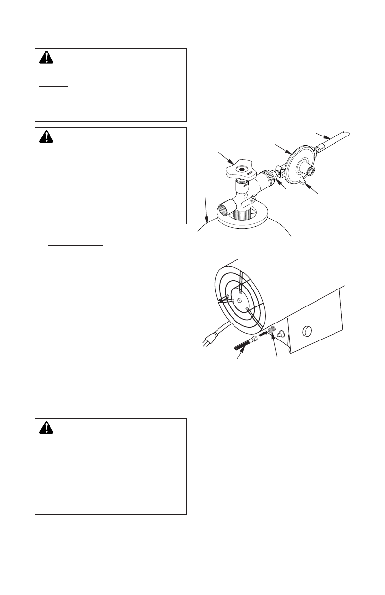
1. Provide propane supply system (see
Propane Supply, page 4).
2. Connect fuel gas connector tting on hose/
regulator assembly to propane tank(s).
Turn counterclockwise into threads on tank
valve. Tighten rmly using wrench.
IMPORTANT: Tighten regulator with vent
pointing down. Pointing vent down protects regulator from weather damage.
3. Connect hose to inlet connector. Tighten
rmly using a wrench.
IMPORTANT: Extra hose or piping may be
used if needed. Install extra hose or piping
between hose/regulator assembly and
propane tank. You must use the regulator
supplied with heater.
4. Open propane supply valve on propane
tank(s) slowly.
Note: If not opened slowly, excess-ow
check valve on propane tank may stop
gas ow. If this happens, close propane
supply valve and open again slowly.
5. Check all connections for leaks.
6. Close propane supply valve.
Hose
Supply
Valve
Propane
Tank
Figure 3 - Regulator With Vent Pointing
Figure 4 - Hose and Inlet Connector
(Heater may vary from illustration)
Hose
Regulator
Down
Inlet Connector
Fuel Gas
Connector
Vent
(pointing
down)
VENTILATION
Provide a fresh air o pe ni ng of at least
WARNING: Follow the mini-
mum fresh, outside air ventila-
tion requirements. If proper
fresh, outside air ventilation is
not provided, carbon monoxide
poisoning can occur. Provide
proper fresh, outside air ventilation before running heater.
121231-01B 5
www.desatech.com
three square feet for each 100,000 Btu/Hr
(105,500 k/j) rating. Provide extra fresh air
if more heaters are being used.
OPERATION
WARNING: Review and understand the warnings in the
Safety section, page 2. They are
needed to safely operate this
heater. Follow all local codes
when using this heater.
TO START HEATER
1. Follow all installation, ventilation and
safety information.
2. Locate heater on stable and level surface.
Make sure strong drafts do not blow into
front or rear of heater.
3. Plug power cord of heater into a 3-prong,
grounded extension cord. Extension cord
must be at least 6 feet (1.83 m) long,
UL/CSA listed and of a proper size.
Extension Cord Size Requirement
Up to 100 feet (30.5 m) long, use 16 AWG
rated cord.
101 to 200 feet (30.78 to 61 m) long, use
14 AWG rated cord.
4. Plug extension cord into a 120 volt/60
hertz, three-hole, grounded outlet. Motor
will start. Fan will turn, forcing air out front
of heater.
5. Open propane supply valve on propane
tank(s) slowly.
Note: If not opened slowly, excess-ow
check valve on propane tank will stop
gas ow. You may hear a click from the
excess-ow check valve closing. If this
happens, reset the excess-ow check
valve by closing propane supply valve
and open again slowly.
6. Press and hold in fuel valve button. Heater
should ignite within a few seconds.
Note: If heater fails to ignite, hose may
have air in it. If so, keep fuel valve button
pressed and wait 20 seconds. Release
automatic control valve button and wait 20
seconds for unburned fuel to exit heater.
Repeat step 6.
7. After heater ignites, wait 30 seconds. This
activates the automatic control system.
Release the control knob.
8. When burner remains lit, set heater at the
desired heat level by turning the variable
Btu control knob counterclockwise. If
burner goes out, turn off gas. Turn variable Btu control knob fully clockwise to
the lowest position. Check fuel supply. If
adequate fuel is available, restart heater
beginning at step 1.
TO STOP HEATER
1. Tightly close propane supply valve on
propane tank(s).
2. Wait a few seconds. Heater will burn gas
left in supply hoses.
3. Unplug heater.
STORAGE
CAUTION: Disconnect heater
from propane supply tank(s).
1. Store propane tank(s) in safe manner. See
Chapter 5 of Standard for Storage and
Handling of Liqueed Petroleum Gases,
ANSI/NFPA 58 and the Propane Installa-
tion Code CAN/CGA B149.2. Follow all
local codes. Always store propane tanks
outdoors.
www.desatech.com
2. Place plastic cover caps over brass ttings
on inlet connector and hose/regulator assembly.
3. Store in dry, clean and safe place. Do
not store hose/regulator assembly inside
heater combustion chamber.
4. When taking heater out of storage, always
check inside of heater. Insects and small
animals may place foreign objects in
heater. Keep inside of heater free from
combustible and foreign objects.
121231-01B6
MAINTENANCE
2. Inspect heater before each use. Check
WARNINGS
• Never service heater while it
is plugged in, connected to
propane supply, operating or
hot. Severe burns and electrical shock can occur.
• Keep heater clear and free
from combustible materials,
gasoline and other ammable
vapors and liquids.
• Do not block the ow of com-
bustion or ventilation air.
1. Keep heater clean. Clean heater annually
or as needed to remove dust and debris. If
heater is dirty or dusty, clean heater with
a damp cloth. Use household cleaners on
difcult spots.
connections for leaks. Apply mixture of
liquid soap and water to connections.
Bubbles forming show a leak. Correct all
leaks at once.
3. Inspect hose/regulator assembly before
each use. If hose is highly worn or cut,
replace with hose specied by manufacturer.
4. Have heater inspected yearly by a quali-
ed service agency.
5. Keep inside of heater free from combustible and foreign objects. Remove motor
and other internal parts if needed to clean
inside of heater (see Service Procedures,
page 8).
6. Clean fan blades each season or as
needed (see Fan, page 9).
TROUBLESHOOTING
WARNING: Never service heater while it is plugged in, connected
to propane supply, operating or hot. Severe burns and electrical
shock can occur.
OBSERVED PROBLEM
Fan does not turn when
heater is plugged in
Heater will not ignite
121231-01B 7
POSSIBLE CAUSE
1. No electrical power to heater
2. Fan hitting inside of heater
shell
3. Fan blades bent
4. Defective motor
1. User did not follow installation or operation instructions
properly
2. No spark at spark plug. To
test for spark, follow steps 1
to 8 under Spark Plug, page
9. If you see spark at spark
plug, have heater serviced
by qualied service person.
If no spark seen:
A) Loose or disconnected
spark plug wire
B) Bad spark plug
C) Bad spark transformer
www.desatech.com
REMEDY
1. Check voltage to electrical
outlet. If voltage is good, check
heater power cord for breaks
2. Adjust motor/fan mount to
keep fan from hitting inside of
heater shell. Bend fan mount
if necessary
3.
Replace fan. See Fan, page 9
4. Replace motor. See Motor,
page 8
1. Repeat installation and operat io n i nstructio ns . S ee
Installation, page 5 and Operation, page 6
2. A) Check spark plug wire.
Tigh ten or r eattach loose
spark plug wire. See Figure
8, page 9 for spark plug wire
location
B) Replace spark plug. See
Spark Plug, page 9
C) Replace spark transform-
er. See Spark Transformer,
page 9
TROUBLESHOOTING
Continued
OBSERVED PROBLEM
Heater shuts down while
running
WARNING: Use
only in areas free of
high dust content.
POSSIBLE CAUSE
1. Pro pan e sup ply ma y be
inadequate
2. High surrounding air temperat ure causin g thermal
limit device to shut down
heater
3. Restricted air ow
4. Damaged fan
5. Excessive dust or debris in
surrounding area
SERVICE PROCEDURES
WARNING: Never service
heater while it is plugged in,
connected to propane supply,
operating or hot. Severe burns
and electrical shock can occur.
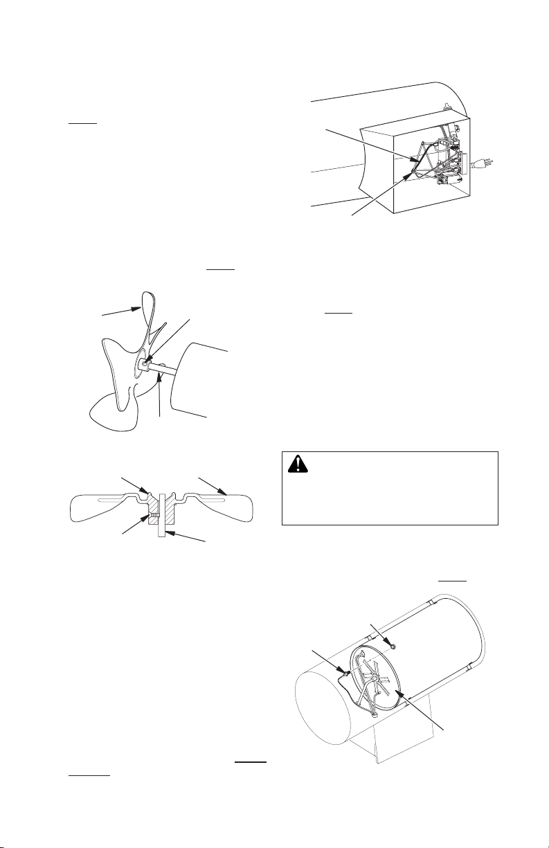
MOTOR
1. With heater on its side, remove access
panel.
2. Access ground screw through underside
of heater base. Remove ground screw.
Disconnect the green motor wire and the
green power cord wire from underside of
shell (see Figure 5).
3. Remove two black wires from motor to
terminal board.
4. Carefully push motor wires through hole
in bottom of shell.
5. Remove screws holding motor mount to
shell. Use nut-driver (see Figure 5).
6. Carefully pull motor and fan out of shell.
IMPORTANT: Be careful not to damage
fan. Do not set motor and fan down with
the weight resting on fan. This could damage fan pitch.
7. Use hex wrench to loosen setscrew which
holds fan to motor shaft.
8. Remove fan. Be careful not to damage
the fan blade pitch.
9. Use nut driver to remove two nuts that
attach motor to motor mount.
10. Discard old motor.
11. Attach motor to motor mount with two
nuts. Tighten nuts rmly.
REMEDY
1. A) Rell tank
B) Provide additional and/or
larger tanks. See Propane
Supply, page 4
2. This can happen when running
heater in temperatures above
85° F (29° C). Run heater in
cooler temperatures
3. Check heater inlet and outlet.
Remove any obstructions
4.
Replace fan. See Fan, page 9
5. Clean heater. See Maintenance, page 7
12. Replace fan on motor shaft. Make sure
set screw contacts at surface on motor
shaft.
13. Tighten set screw rmly (40-50 inch-
pounds [46.08-57.60 kg-cm]).
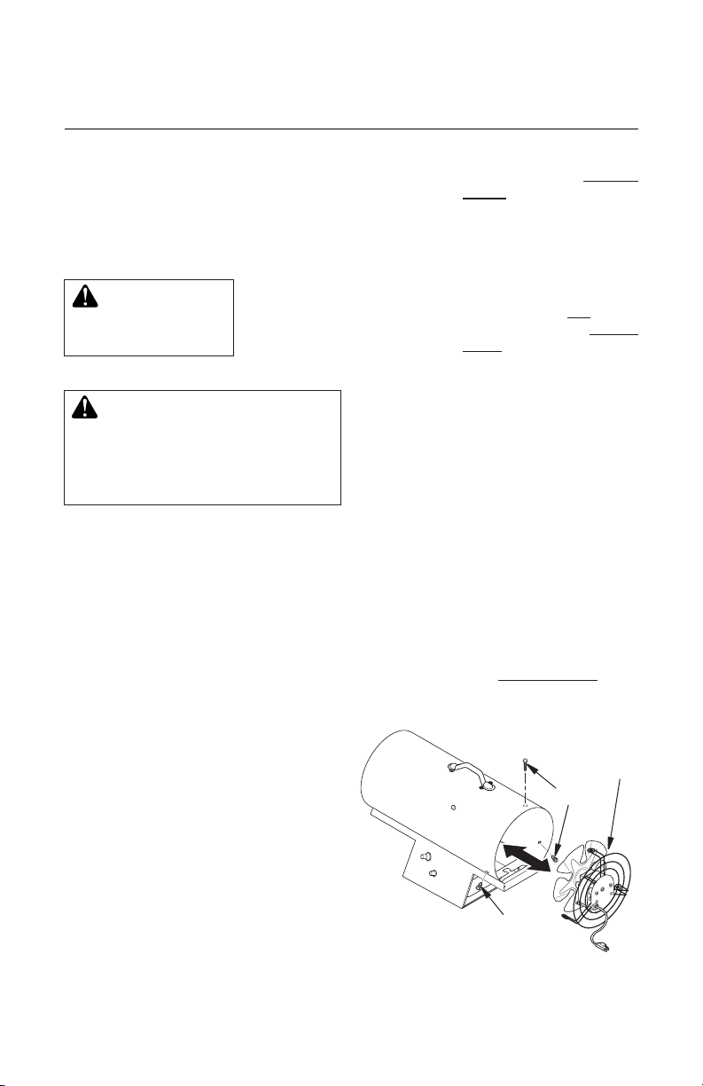
14. Carefully route motor wires through hole
in shell. Place motor, motor mount and fan
guard into rear of heater shell, as shown
in Figure 5.
15. Insert screws through heater shell and
into motor mount. Tighten screws rmly.
16. Turn heater on its side to access opening
in bottom of base. Connect green wires
from motor, transformer and power cord
to heater shell using ground nut.
17. Attach two black wires from motor to terminal board (see Wiring Diagram, page
10, for correct locations).
18. Replace access panel.
Motor and
Fan Guard
Screw
Screw
Figure 5 - Removing Motor and Fan
Guard from Heater (Heater may vary
from illustration)
www.desatech.com
121231-01B8
SERVICE PROCEDURES
Continued
FAN
1. Remove motor, motor mount and fan (see
Motor, steps 1 through 8, page 8).
2. Clean fan using soft cloth moistened with
kerosene or solvent.
3. Dry fan thoroughly.
4. Replace fan on motor shaft. Make sure
setscrew is touching back of at surface
on motor shaft (see Figure 6).
5. Place setscrew on at of shaft. Tighten
se ts crew firmly (40 -5 0 inch- po unds
[46.08-57.60 kilogram-centimeters]).
6. Place motor, motor mount and fan guard
into rear of heater shell (see Motor, steps
14 through 18, page 8).
Fan
Motor Shaft
Figure 6 - Fan, Motor Shaft and Setscrew
Location
Hub
Setscrew
Figure 7 - Fan Cross Section
Setscrew
Fan
Motor Shaft
SPARK TRANSFORMER
1. Remove access panel.
2. Locate and disconnect white, black and
orange wires from spark transformer.
3. Remove screw holding spark transformer
to base. Remove sheet metal nut on transformer and install on new transformer.
Discard spark transformer.
4. Install new spark transformer. Position
new spark transformer in same manner
as old transformer.
5. Connect white, black and orange wires
to new spark transformer. Connect wires
to correct terminals as noted in Wiring
Diagram, page 10.
6. Replace access panel.
121231-01B 9
www.desatech.com
Spark
Plug
Wire
Bushing
Figure 8 - Removing Spark Plug Wire
from Spark Transformer (Heater may
vary from illustration)
SPARK PLUG
1. Remove motor, motor mount and fan guard
(see Motor, steps 1 through 6, page 8).
2. Remove orange spark plug wire from
spark plug.
3. From front of heater loosen 3/4" hex nut
holding spark plug in place (see Figure 9).
4. Remove spark plug from rear head.
5. Install new spark plug. Attach spark plug
to rear head with ignitor hex nut removed
in step 3.
6. Attach spark plug wire.
7. Test for spark.
WARNING: Make sure heater
is disconnected from propane
supply. Heater could ignite causing severe burns.
Plug into extension cord and watch for
spark at spark plug.
8. Place motor, motor mount and fan guard
into rear of heater shell (see Motor, steps
14 through 18, page 8).
3/4" Hex
Head Nut
Spark Plug
Rear Head
Figure 9 - Removing Spark Plug Nut and
Spark Plug (Heater may vary from illustration)
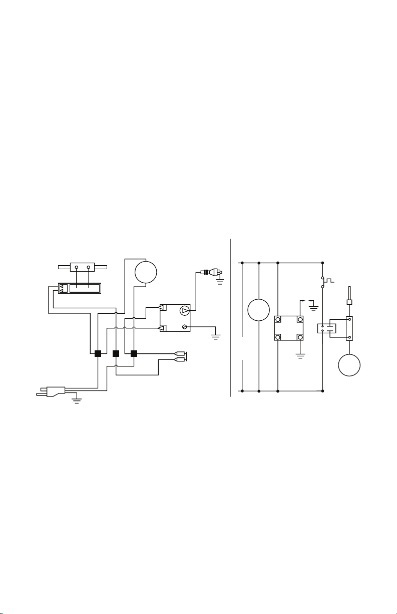
SPECIFICATIONS
Black
Black** or
Orange**
L1
L2
White
Red* or Ye llow*
Red* or Ye llow*
White
White
Black
Black
Black
Black
Green
Orange
Orange
Thermocouple
CO
NNECTION DIAGRAM
SC
HEMAT IC DIAGRAM
Relay
Motor
Spark Plug
Spark Plug
Ignitor
High-Limit
Switch
• If any original wiring as supplied with the heater must be replaced, it must be replaced with
type AWG 105° C wire or its equivalent except as indicated (*Type SF2-200. **SGI-250° C)
Line Cord
Motor
High Limit
Switch
White
Black
120V
60HZ
Gas
Va lve
Relay
Thermocouple
L1
L2
Ignitor
All Models
• Propane/LP Gas
• Gas Supply Pressure to Regulator:
Max - Bottle Pressure, Min - 5 psig (34.5 kPa)
• Gas Supply Pressure Regulator Out:
28" WC (6.97 kPa)
• Electrical Input: 120V, 60 Hz, 1Ø, 3a
• Direct Spark Ignition
• Primary Flame Control:
Thermocouple operated gas valve
• Minimum Ambient Temp. Rating:
-20° F (-29° C)
• Heated Air Output: 350 CFM (9.91 m3/min)
WIRING DIAGRAM
55,000 Btu/Hr Models
• 30-55,000 Btu/Hr (8.8 - 16.1 kW)
• Fuel Consumption:
1.4 - 2.6 pounds/hr (0.70 - 1.28 kg/hr)
• Average Air Temp. Rise: 200° F (111° C)
85,000 Btu/Hr Models
• 50-85,000 Btu/Hr (14.6 - 25.0 kW)
• Fuel Consumption:
2.3 - 3.9 pounds/hr (1.04 - 1.77 kg/hr)
• Average Air Temp. Rise: 200° F (111° C)
125,000 Btu/Hr Models
• 75-125,000 Btu/Hr (21.9 - 36.6 kW)
• Fuel Consumption:
3.5 - 5.8 pounds/hr (1.59 - 2.63 kg/hr)
• Average Air Temp. Rise: 400° F (232° C)
www.desatech.com
121231-01B10

REPLACEMENT PARTS
Note: Use only original replacement parts.
This will protect your warranty coverage for
parts replaced under warranty.
PARTS UNDER WARRANTY
Contact authorized dealers of this product. If
they can’t supply original replacement part(s),
call DESA Heating, LLC at 1-866-672-6040.
When calling DESA Heating, LLC, have
ready:
• your name
• your address
• model and serial numbers of your heater
• how heater was malfunctioning
• purchase date
Usually, we will ask you to return the part to
the factory.
PARTS NOT UNDER WARRANTY
Contact authorized dealers of this product. If
they can’t supply original replacement part(s),
call DESA Heating, LLC at 1-866-672-6040 for
referral information. A list of authorized dealers
can be found by visiting www.desatech.com.
When calling DESA Heating, LLC, have
ready:
• model and serial numbers of your heater
• the replacement part number
TECHNICAL SERVICE
You may have further questions about installation, operation, or troubleshooting. If so, contact DESA Heating, LLC at 1-866-672-6040.
When calling please have your model and
serial numbers of your heater ready.
You can also visit DESA Heating, LLC’s web
site at www.desatech.com.
121231-01B 11
www.desatech.com
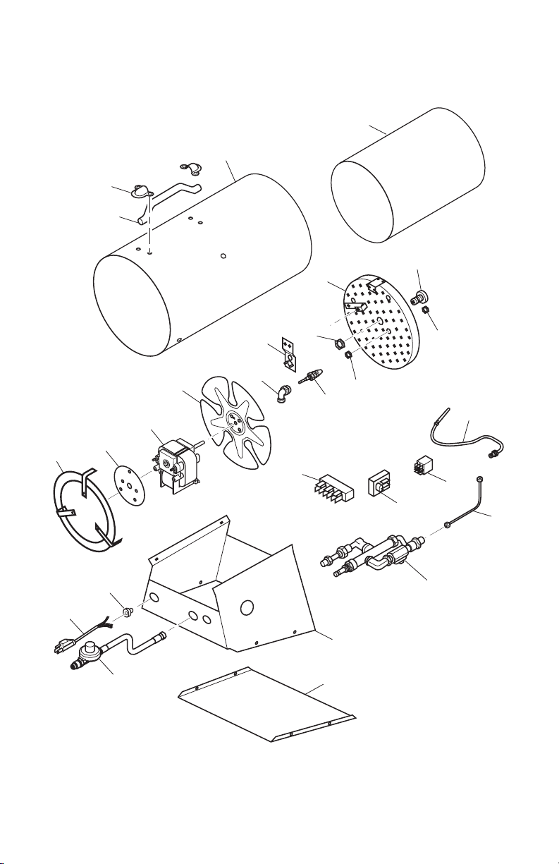
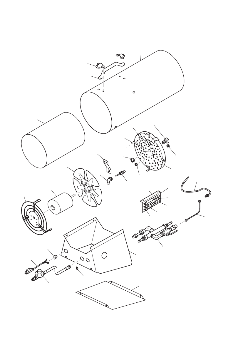
PARTS
6
7
4
18
19
17
14
15
13
3
1
23
21
22
24
20
10
9
8
2
5
25
26
14
16
11
12
MODELS BLP55VA, REM55PVA, RLP55VA AND TB115A
www.desatech.com
121231-01B12

PARTS
MODELS BLP55VA, REM55PVA, RLP55VA AND TB115A
This list contains replaceable parts used in your heater. When ordering parts, follow the instructions
listed under Replacement Parts on page 11 of this manual.
KEY
NO. PART NO. DESCRIPTION QTY
1 121246-01 Grill Assembly 1
2 121247-01 Motor Mounting Bracket 1
3 121206-01 Motor Assembly 1
4 121209-01 Fan 1
5 121406-01 Outer Cylinder, Red (RLP55VA) 1
121406-04 Outer Cylinder, Black (REM55PVA) 1
121406-02 Outer Cylinder, Orange (TB115A) 1
121406-03 Outer Cylinder, Yellow (BLP55VA) 1
6 121216-01 Handle 1
7 121217-01 Clip Handle Mounting 2
8 121205-01 Hose/Regulator Assembly 1
9 113864-01 Power Cord 1
10 113865-01 Strain Relief Bushing 1
11 113887-01 Male Elbow Fitting 1
12 121213-01 Spark Plug 1
13 121244-01 High Limit Switch Control Assembly 1
14 113886-01 Nut, Spark Plug 2
15 121224-01 Flame Holder Assembly 1
16 113888-02 Nut orice Mounting 1
17 121245-01 Orice, LP Assembly 1
18 ** Middle Cylinder Assembly 1
19 113884-01 Thermocouple 1
20 121212-01 Fuel Tube Assembly 1
21 113875-01 Relay Assembly 1
22 113924-01 Ignition Control 1
23 113872-01 Terminal Board 1
24 121230-01 Control Valve Assembly 1
113870-01 Elbow Street Fitting 2
113869-01 Coupling Fitting 2
113868-01 Male Connector Fitting 1
113876-01
113873-01 Ball Valve 1
113871-01 Valve 1
25 121410-01 Control Box Assembly 1
26 121411-01 Bottom Panel 1
121238-01 Pressure Ignition Wire 1
121237-03 High Limit Wire 1
121236-01 Ground Wire 1
121215-01 Knob 1
** Not a eld replaceable part.
Female Connector Fitting
PARTS AVAILABLE - NOT SHOWN
1
121231-01B 13
www.desatech.com
ILLUSTRATED PARTS BREAKDOWN
26
25
2
6
28
9
13
20
12
5
10
3
4
21
16
15
27
17
19
18
22
23
24
1
14
29
12
7
8
11
MODELS 85-FACA, RLP85VA AND SPC-85
www.desatech.com
121231-01B14

PARTS LIST
MODELS 85-FACA, RLP85VA AND SPC-85
This list contains replaceable parts used in your heater. When ordering parts, follow the
instructions listed under Replacement Parts on page 11 of this manual.
KEY
NO. PART NO. DESCRIPTION QTY.
1 121407-01 Outer Cylinder Assembly, Red (RLP85VA) 1
121407-02 Outer Cylinder Assembly, Red (85-FACA) 1
121407-05 Outer Cylinder Assembly, Orange (SPC-85A) 1
2 121209-01 Fan 1
3 121207-01 Motor Assembly 1
4 121246-02 Motor Grill 1
5 121225-03 Flame Holder Assembly 1
6 ** Middle Cylinder Assembly 1
7 113888-02 Nut Orice Mounting 3/4-16 1
8 113931-01 Male Elbow Fitting 1
9 113884-01 Thermocouple 1
10 121244-01 High Limit Control Assembly 1
11 121213-02 Spark Plug, 1/8 Gap 1
12 113886-01 Nut-Spark Plug 2
13 121245-03 Orice Assembly 1
14 121357-01 Control Box Assembly 1
15 113924-01 Ignition Relay Bracket 1
16 113872-01 Terminal Board 1
17 113867-01 Spark Ignition, 115V Hi-Lo Mini Ignitor 1
18 121212-02 Fuel Tube Assembly 1
19 121230-02 Control Valve Assembly 1
113869-01 Fitting, Coupling 1
113868-01 Fitting, Male Connector 1
113871-01 Valve 1
113928-01 Ball Valve, Variable Rate 1
113929-01 Female Connector Fitting 1
113870-01 Fitting, Elbow 2
20 121248-01 Spacer, TC Bracket 1
21 121410-04 Control Panel Assembly 1
22 113865-01 Strain Relief Bushing 1
23 113864-01 Power Cord 1
24 121205-01 Hose/Regulator Assembly 1
25 121217-01 Clip Handle Mounting 2
26 121216-01 Handle 1
27 113875-01 Relay 1
28 113923-01 Bracket, TC 1
29 121411-04 Access Panel 1
121238-01 Pressure Ignition Wire 1
121237-03 High Limit Wire 1
121236-01 Ground Wire 1
121215-01 Knob 1
121235-01 Ignitor/Relay Board Assembly 1
** Not a eld replaceable part.
PARTS AVAILABLE - NOT SHOWN
121231-01B 15
www.desatech.com
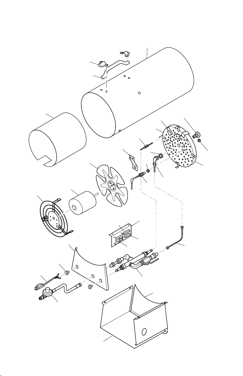
PARTS
5
6
3
13
10
18
12
11
14
15
9
2
1
20
19
22
21
23
24
17
28
29
30
26
4
27
31
14
16
7
8
25
MODELS 125-FA, BLP125VA, REM125PVA, RLP125VA AND SPC-125A
www.desatech.com
121231-01B16

PARTS
MODELS 125-FA, BLP125VA, REM125PVA, RLP125VA AND SPC-125A
This list contains replaceable parts used in your heater. When ordering parts, follow the
instructions listed under Replacement Parts on page 11 of this manual.
KEY
NO. PART NO. DESCRIPTION QTY
1 113919-01 Grill Assembly 1
2 121207-01 Motor Assembly 1
3 121210-01 Fan 1
4 121408-01 Outer Shell Cylinder Assembly, Red (RLP125VA) 1
121408-02 Outer Shell Cylinder Assembly, Red (125-FA) 1
121408-03 Outer Shell Cylinder Assembly, Yellow (BLP125VA) 1
121408-04 Outer Shell Cylinder Assembly, Black (REM125PVA) 1
121408-05 Outer Shell Cylinder Assembly, Orange (SPC-125A) 1
5 121216-01 Handle 1
6 121217-01 Clip Handle Mounting 2
7 113931-01 Male Elbow Fitting 1
8 121213-02 Spark Plug, 1/8 (3.18 mm) Gap 1
9 121244-01 High Limit Switch Control Assembly 1
10 113923-01 Thermocouple Bracket 1
11 121248-01 Thermocouple Spacer 1
12 121245-02 Orice, LP Assembly 1
13 ** Middle Cylinder Assembly 1
14 113886-01 Nut, Spark Plug 2
15 121225-01 Flame Holder Assembly 1
16 113888-02 Nut orice Mounting 1
17 121212-02 Fuel Tube Assembly 1
18 113884-01 Thermocouple 1
19 113924-01 Bracket Ignition Relay 1
20 113872-01 Terminal Board 1
21 114150-01 Steel Spacer 1
22 113875-01 Relay Assembly 1
23 113867-01 Ignitor 1
24 114151-01 Spacer, PC Standoff Nylon 3
25 121230-02 Control Valve Assembly 1
114153-01 Elbow Street Fitting 2
114159-01 Ball Valve, Variable Rate 1
113929-01 Female Connector Fitting 1
113869-01 Coupling Fitting 1
113868-01 Male Connector Fitting 1
113871-01 Valve 1
26 114158-01 Flat Washer 1
27 121410-02 Control Box Assembly 1
28 113865-01 Strain Relief Bushing 1
29 113864-01 Power Cord 1
30 121205-01 Hose/Regulator Assembly 1
31 121411-02 Access Panel 1
121238-01 Pressure Ignition Wire 1
121237-03 High Limit Wire 1
121236-01 Ground Wire 1
121215-01 Knob 1
121235-01 Ignitor/Relay Board Assembly 1
** Not a eld replaceable part.
121231-01B 17
PARTS AVAILABLE - NOT SHOWN
www.desatech.com

WARRANTY
KEEP THIS WARRANTY
Model (
located on product or identication tag
Serial No. (
located on product or identication tag
Date Purchased __________________________
Keep receipt for warranty verication.
DESA HEATING, LLC LIMITED WARRANTIES
Standard Warranty: DESA Heating, LLC warrants this new product and any parts thereof to be free from
defects in material and workmanship for a period of one (1) year from the date of rst purchase from an
authorized dealer provided the product has been installed, maintained and operated in accordance with
DESA Heating, LLC’s warnings and instructions.
For products purchased for commercial, industrial or rental usage, this warranty is limited to 90 days from
the date of rst purchase.
Factory Reconditioned Products
Limited Warranty: DESA Heating, LLC warrants factory reconditioned products and any parts thereof
to be free from defects in material and workmanship for 30 days from the date of rst purchase from an
authorized dealer provided the product has been installed, maintained and operated in accordance with
DESA Heating, LLC’s warnings and instructions.
Terms Common to All Warranties
The following terms apply to all of the above warranties:
Always specify model number and serial number when contacting the manufacturer. To make a claim under
this warranty the bill of sale or other proof of purchase must be presented.
This warranty is extended only to the original retail purchaser when purchased from an authorized dealer,
and only when installed by a qualied installer in accordance with all local codes and instructions furnished
with this product.
This warranty covers the cost of part(s) required to restore this product to proper operating condition and
an allowance for labor when provided by a DESA Heating, LLC Authorized Service Center or a provider
approved by DESA Heating, LLC. Warranty parts must be obtained through authorized dealers of this product and/or DESA Heating, LLC who will provide original factory replacement parts. Failure to use original
factory replacement parts voids this warranty.
Travel, handling, transportation, diagnostic, material, labor and incidental costs associated with warranty
repairs, unless expressly covered by this warranty, are not reimbursable under this warranty and are the
responsibility of the owner.
Excluded from this warranty are products or parts that fail or become damaged due to misuse, accidents,
improper installation, lack of proper maintenance, tampering, or alteration(s).
This is DESA Heating, LLC’s exclusive warranty, and to the full extent allowed by law; this express warranty
excludes any and all other warranties, express or implied, written or verbal and limits the duration of any
and all implied warranties, including warranties of merchantability and tness for a particular purpose to one
(1) year on new products and 30 days on factory reconditioned products from the date of rst purchase.
DESA Heating, LLC makes no other warranties regarding this product.
DESA Heating, LLC’s liability is limited to the purchase price of the product, and DESA Heating, LLC shall
not be liable for any other damages whatsoever under any circumstances including indirect, incidental, or
consequential damages.
Some states do not allow limitations on how long an implied warranty lasts or the exclusion or limitation of
incidental or consequential damages, so the above limitation or exclusion may not apply to you.
This warranty gives you specic legal rights, and you may also have other rights which vary from state to state.
For information about this warranty contact:
New Products
) _____________________________
) __________________________
DESA Heating, LLC
2701 Industrial Drive
Bowling Green, KY 42101
www.desatech.com
1-866-672-6040
121231-01
Rev. B
10/08
 Loading...