

Desa SPV 12 EH Installation And Operation Manual
Installation and operation manual
SPLIT AIR CONDITIONER
SPV 12 EH

TABLE OF CONTENS
Technical specification 2
Safety instructions 3
Components 5
Assembly instructions installation 6
Assembly instructions connection 10
Assembly instructions disconnection 14
Remote control 16
Display panel 17
Operation 18
Remote control notes 21
Maintenance 22
Maintenance before and after the season 23
Troubleshooting 24
1
2
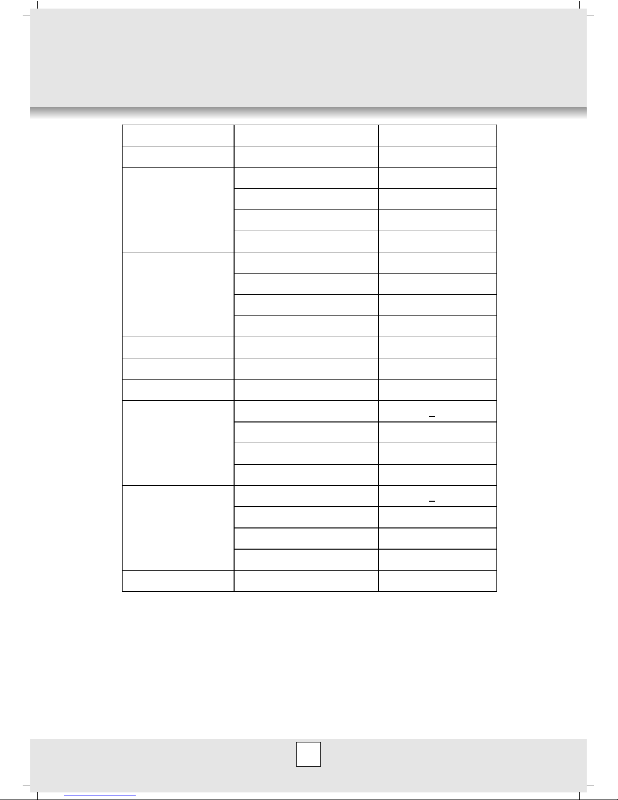
TECHNICAL SPECIFICATION
Please note:
1. Information may vary for technical reasons
2. Measuring condition for above is based on regulation EN14511
Model
SPV 12 EH
Power Supply
V/Hz 220÷240 / 50Hz
Capacity (W) 3500
Power Consumption (W) 1220
Operating Current (A) 5,5
Cooling
EER (W/W) 2,87
Capacity (W) 3800
Power Consumption (W) 1180
Operating Current (A) 5,4
Heating
COP (W/W) 3,22
Airflow Volume
m3/hr (Cooling/Heating) 520 / 560
Dehumidifying
l/h 1,0
Refrigerant
R407c (g) 850
Noise Level (db(A)) <43
Dimensions WxHxD (mm) 795x270x190
Packing WxHxD (mm) 860x320x400
Indoor Unit
Net/Gross Weight (kg) 11/16
Noise Level (db(A)) <53
Dimensions WxHxD (mm) 800x540x250
Packing WxHxD (mm) 888x590x344
Outdoor Unit
Net/Gross Weight (kg) 33/38
Suitable Area
m3 80

3
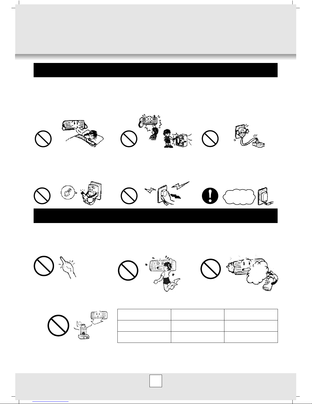
SAFETY INSTRUCTIONS
! Please read carefully this Manual and Safety Instructions before operating the
appliance.
! Warnings and instructions under the heading “CAUTION / NOTES” warn against occurrence
of serious problems, or inform on how to optimize appliance operation. Reading and
observing such notes is critical for ensuring safe and efficient operation of the appliance.
! Symbols used in this Manual have the following meanings:
Formal
prohibition
Follow the
instructions
Ensure continuity
of earthing
Disconnect
power supply
! After you read this Manual please keep it at hand and protect from damage or loss.
1. Do not install the appliance in places
exposed to leakage of flammable
gases.
Gas leaking and accumulating around the
appliance may cause fire.
1. Electric installation is to be fitted with
differential current switch.
When the appliance is connected to
improperly protected installation it may
cause electric shock.
2. Electric installation is to be fitted with
differential current switch.
When the appliance is connected to improperly
protected installation it may cause electric
shock.
3. Make sure the condensate tube is
placed correctly, so that water can drain
out.
Improper placement of condensate tube
can result in flooding of premises and
dampening of furniture.
4. Make sure the housing of external module
is earthed.
Earthing conductors cannot be running along
gas pipes, water pipes, lighting arrester wire or
telephone earthing wire. Improper installation of
earthing conductor may result in electric shock.
4
Never expose your body to
cold air for a long time, as it
may have adverse effect to
your health.
Never introduce any objects or
body parts to internal and
external parts of the appliance.
Never use extension cords
or branch-joints to connect
the appliance to power
supply.
OPERATION INSTRUCTIONS
Protect power cord from
damage.
Never switch the appliance on
or off by removing plug.
Before switching on, always
check if the appliance is
correctly connected to power
supply.
DANGER!!!
CAUTION!!!
Never touch switches or
buttons with wet hands.
Never hang on the
appliance.
Never spray flammable products
(such as insecticides) near the
appliance.
Never place combustion devices
(generating fire) near from the
air-conditioner air outlet.
Air-conditioner working range:
INSIDE OUTSIDE
COOLING
HEATING
O O
18 C - 43 C
O O
9 C - 43 C
O O
9 C - 30 C
O O
9 C - 30 C
Air-conditioner is designed to operate within temperature range as in the table above! The appliance
can be operated in below zero temperatures after prior adaptation by authorized service center. For details
contact your authorized service center or retailer.
5
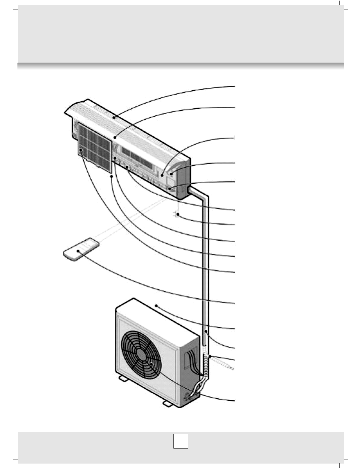
COMPONENTS
Indoor unit
Outdoor unit
Air outlet
Drainage hose
Connecting pipe and cable
Air inlet
Remote controller
Air filter
Air outlet
Vertical louver
Power plug
Horizontal louver
Indicate lamp & signal
receiving window
Emergency switch
Temperature sensor
Air intake grilles
Air inlet
Fig. 1

6
ASSEMBLY MANUAL
– INSTALLATION
1. Installation and connection.
A. External module
External module is to be installed in horizontal position
Option A Option B
Standing on
ground / platform
Wall-mounted
on support
(optional)
External module is to
be installed keeping
the minimum offsets
from walls, ceilings, etc.
0,6m
min
0,15m
min
0,6m
min
0,15m
min
0,6m
min
Note:
To en sure s elf -d rai nin g of
condensate (water restored from
air in air-conditioned premises) the
external module is to be mounted
below the Internal module see
Fig.6 “Basic Installation”. It is
however possible to mount the
modules as in Fig.7 “Optional
Installation”.
External
module
Pipeline
(optional)
Basic
installation
Optional
installation
External
module
Internal
module
Internal
module
Bracket spacing
Fig. 2
Fig. 3
Fig. 4
Fig. 5
Fig. 6
Fig. 7
A = 140 mm
B = 510 mm
C = 130 mm
7
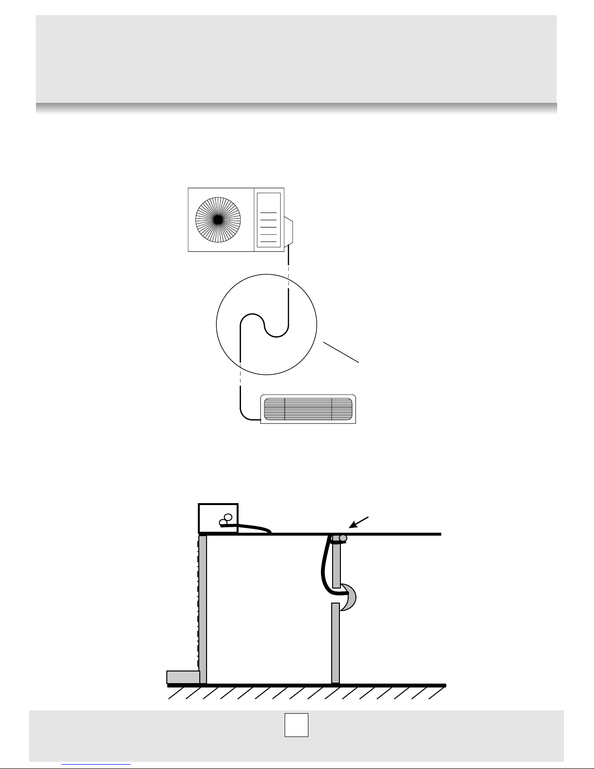
Should you choose optional installation (Fig.7), with external module above the internal
module, bear in mind application of so-called “oil trap” Fig.8.
In case of any installation problems please contact authorized service center or retailer.
Should you decide for esthetics to lead the condensate tube upwards to external module
(see Fig.9), always apply condensate pump. For details contact authorized service center or
retailer.
Condensate
tube
Room 1 Room 2
Condensate
pump
Fig. 8
Fig. 9
oil trap
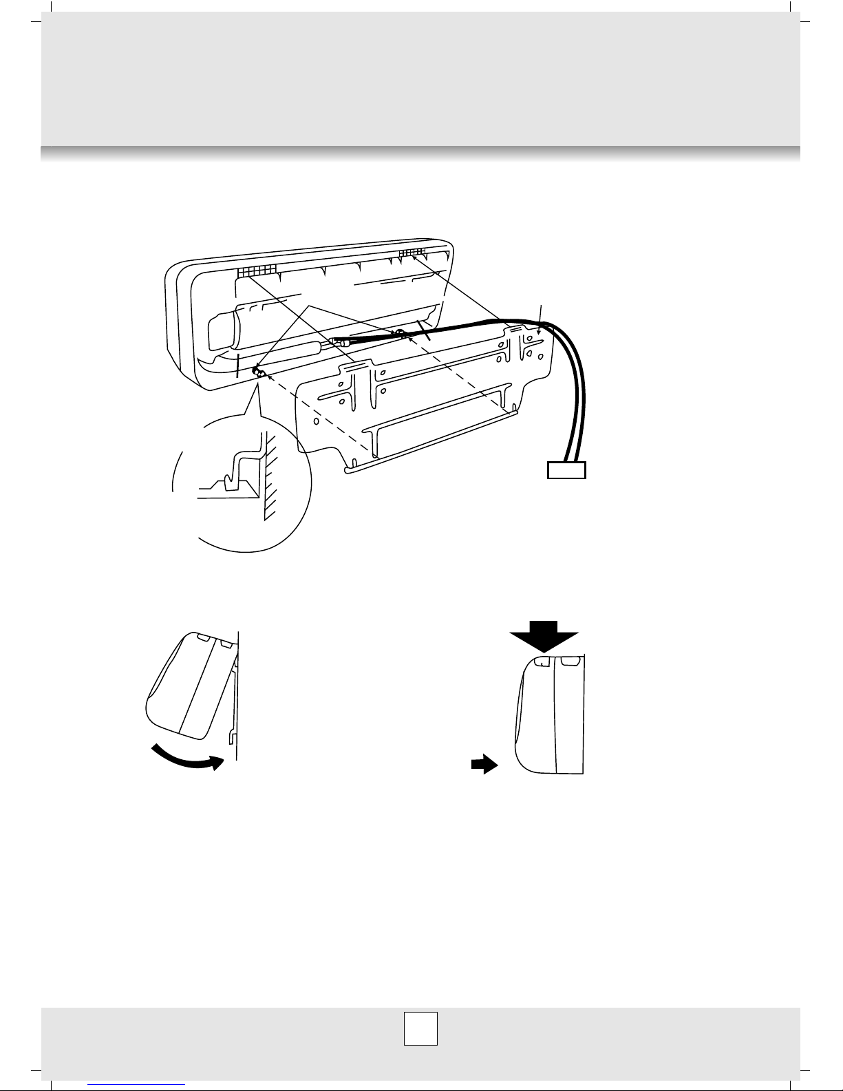
B. Installation of internal module using mounting plate
Internal module is to be mounted in horizontal position.
8
Indoor unit
Mounting plate
Mounting plate
Wall
)
Fixing on internal
module supports
ASSEMBLY
1. Hang upper part of
internal module on
mounting plate
2. Press the module till
its fixed
2 fixt ures2 fixt ures
Fig. 10
Fig. 11
Fig. 12
 Loading...