

Page 1
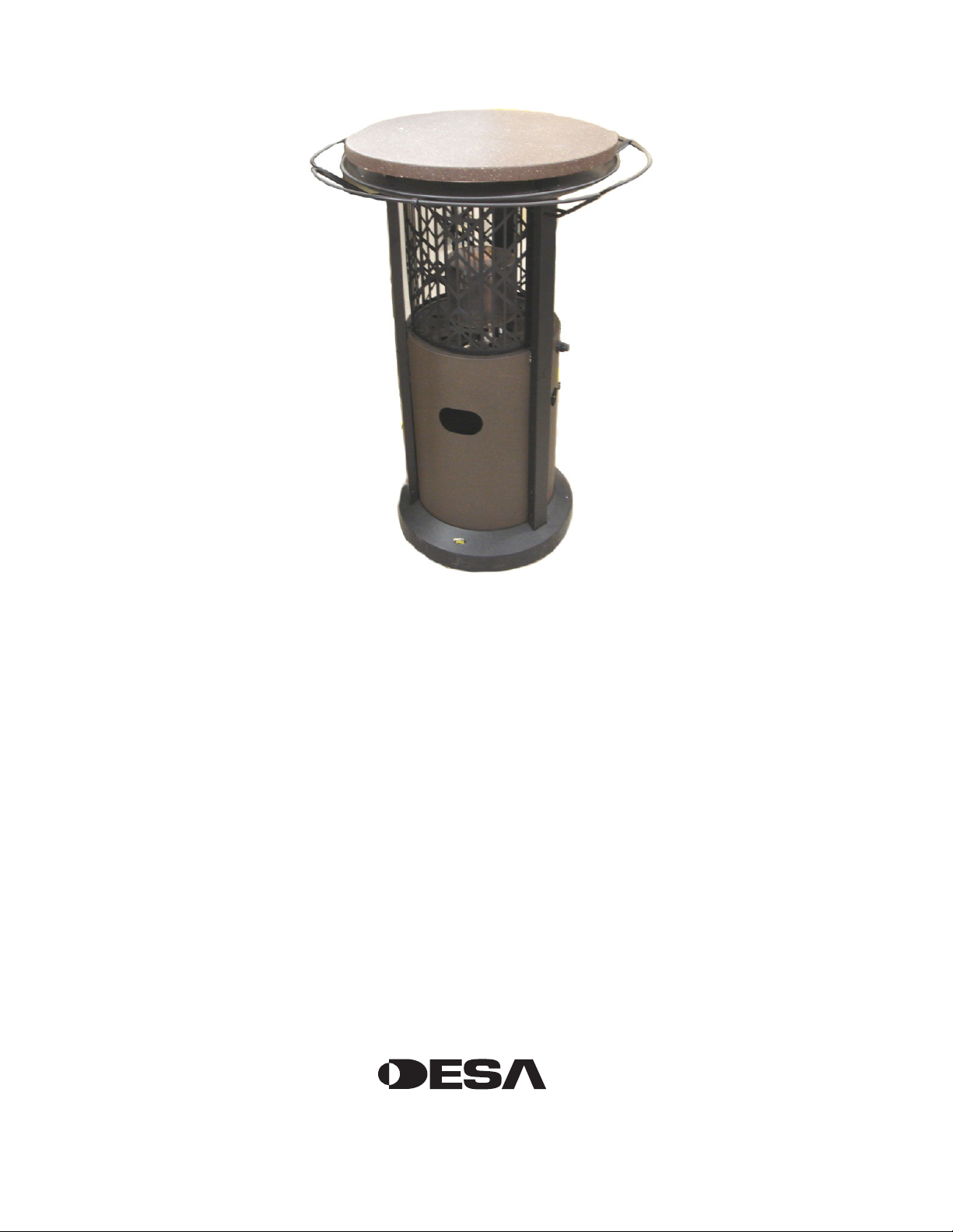
PROPANE/LP BISTRO TABLE INFRARED PATIO HEATER
ASSEMBLY INSTRUCTIONS
MODEL
PBT24HB16
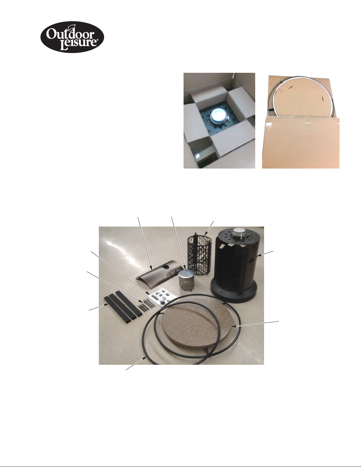
UNPACKING
1. Remove all packing items applied to heater for shipment.
2. Remove all items from carton.
3. Check all items for shipping damage. If heater is damaged,
promptly inform dealer where you bought heater.
You should have the following assembly parts:
Hardware Blister Pack (1), Base Assembly (1), Door Panel Assembly (1), Emitter Assembly (1), Grate Assembly (1), Table Top Assembly (1),
Foot Rail (1), Upper Table Pillar (3), Upper Foot Rail Bracket (3), Foot Rail Bracket (3), (see pages 8 thru 10 of your owner's manual).
Hardware
Blister Pack
Upper and
Lower Foot
Rail Brackets
Upper
Table
Pillars
Door Panel
Assembly
Foot Rail
Emitter Assembly
Grate Assembly
Base Assembly
Table Top
Assembly
Page 2
ASSEMBLY
A
B C
Estimated assembly time: 25 minutes
Tools required:
• #2 Phillips screwdriver
• 3/8" Open end wrench or adjustable wrench
Hardware packet provided with heater may contain more parts than
needed for heater assembly.
Hardware packet contains the following items shown on pages 8
through 10 of your owner's manual:
Knob (1), Propane Tank Retention Chain (1), Retention Hook (2),
and AA Battery (1).
Parts are referenced by designated letter throughout assembly
instructions. Hardware packet contains the following (quantity used
in parenthesis):
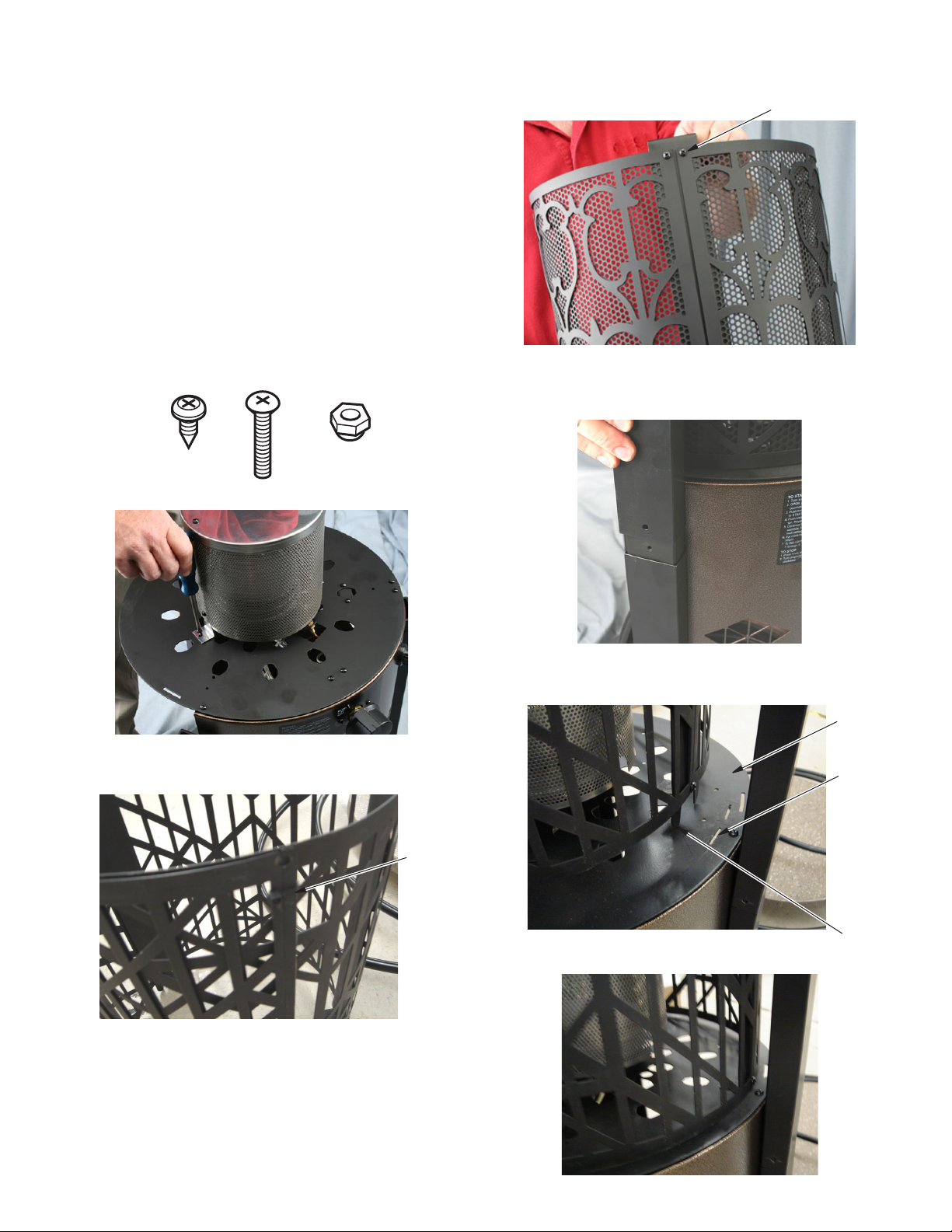
Description Part Number
A 3/8" Screw (53) 119620-02
B 10-24 x 1 1/4" Screw (3) M12345-53
C 10-24 Hex Nut (3) NTC-3BZ
1.
Attach emitter assembly to burner support plate with 2 screws (A).
3.
Complete grate assembly by installing 2 screws into grate pillar (A).
Add Screw
4. Position 3 top support pillars over pillar support connectors.
Secure each set with 1 screw (A) each.
2. Cut wire tie to release grate assembly.
Wire Tie
5.
Locate tabs on grate assembly. Align tabs with slots in burner plate.
6. Slide grate assembly into slots in burner plate.
Burner
Plate
Slot
Tab
www.desatech.com
123224-01A2
Page 3
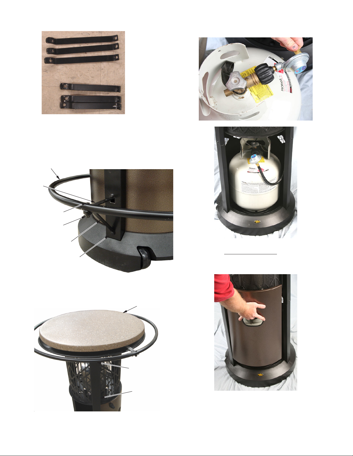
7. Locate upper and lower foot rail brackets.
Lower Foot
Rail Brackets
Upper Foot
Rail Brackets
8. Position upper and lower foot rail brackets as shown. Fasten to
pillar using 2 screws (A) for each pillar.
9. Slide foot rail down over heater assembly. Position foot rail as
shown, and fasten to brackets with 1 bolt (B) and 1 nut (C) for
each pillar.
Foot Rail
Upper
Foot Rail
Bracket
11. Connect regulator to gas cylinder. Gas cylinder will set inside of
cabinet assembly.
Bolt (B)
Nut (C)
Lower Foot
Rail Bracket
Pillar
10. Slide top assembly into position as shown, making sure that grate
tabs engage slots on underside of reector. Fasten in place with
1 screw (A) through each pillar.
Top Assembly
Fasten with
Screw (A)
12. Check for leaks. See Checking for Leaks in your owner's manual.
13. Hang table door panel from slots in burner support plate to cover
inside of heater.
Pillar
123224-01A 3
www.desatech.com
Page 4
DESA Heating, LLC
2701 Industrial Drive
Bowling Green, KY 42101
1-866-672-6040
www.desatech.com
123224-01
Rev. A
02/08
Page 5

CALENTADOR INFRARROJO DE PROPANO O GAS LP PARA
PATIO TIPO MESA BISTRO
INSTRuCCIONES DE ENSAMBLAJE
MODELO PBT24HB16
DESEMPAquE
1. Saque todos los materiales en los que se empacó el calentador
para el envío.
2. Saque todas las piezas de la caja.
3. Revise todas las piezas en busca de daños durante el transporte.
Si el calentador está dañado, infórmelo de inmediato al distribuidor donde lo compró.
La caja contiene las siguientes piezas de montaje:
Paquete con compartimentos individuales de tornillería (1), conjunto de la base (1), conjunto del panel de la puerta (1), conjunto del emi-
sor (1), conjunto de la parrilla (1), conjunto de la parte superior de la mesa (1), barra para pies (1), pilar superior de la mesa (3), soporte
superior de la barra para pies (3), soporte de la barra para pies (3), (consulte las páginas 8 a 10 del manual del propietario).
Paquete de
tornillería
Soportes
superiores e
inferiores de
la barra para
pies
Pilares de
la parte
superior de
la mesa
Conjunto del panel
de la puerta
Barra para pies
Conjunto del
emisor
Conjunto de la parrilla
Conjunto
de la base
Conjunto
de la parte
superior
de la mesa
Page 6

ENSAMBLE
A
B C
Tiempo estimado de ensamble: 25 minutos
Herramientas necesarias:
• Destornillador Phillips N° 2
• Llave española de 3/8" o llave inglesa ajustable
El paquete de tornillería que se incluye con el calentador podría incluir más piezas que las necesarias para ensamblar el calentador.
El paquete con compartimentos individuales de tornillería contiene
los siguientes artículos que se muestran desde la página 8 a la 10
del manual del propietario:
Perilla (1), cadena de retención del tanque de propano (1), gancho
de retención (2), y batería tipo AA (1).
Las piezas se identifican mediante una letra designada a lo largo de
las instrucciones de ensamble. El paquete de tornillería contiene lo
siguiente (las cantidades se muestran entre paréntesis):
Descripción Número de pieza
A Tornillo de 3/8" (53) 119620-02
B Tornillo de 10-24 x 1 1/4" (3) M12345-53
C Tuerca hexagonal de 10-24 (3) NTC-3BZ
3. Complete el ensamblaje de la parrilla instalando 2 tornillos a
través de los pilares de la parrilla (A).
Agregar tornillo
4. Coloque 3 pilares de soporte superiores sobre los conectores
de soporte de los pilares. Fije cada conjunto con 1 tornillo (A).
1. Fije el conjunto del emisor a la placa de soporte del quemador
con 2 tornillos (A).
2. Corte la abrazadera de cable para soltar el conjunto de la parrilla.
Abrazadera
de cable
5. Ubique las lengüetas en el conjunto de la parrilla. Alinee las
lengüetas con las ranuras en la placa del quemador.
Placa del
quemador
Ranura
Lengüeta
6. Deslice el conjunto de la parrilla en las ranuras de la placa del
quemador.
www.desatech.com
123224-01A2
Page 7

7. Ubique los soportes superiores e inferiores de la barra para pies.
Soportes
inferiores de la
barra para pies
Soportes
superiores de la
barra para pies
8. Coloque los soportes superiores e inferiores de la barra para pies
como se muestra. Sujételos al pilar utilizando 2 tornillos (A) para
cada pilar.
9. Deslice hacia abajo la barra para pies sobre el conjunto del calentador. Coloque la barra para pies como se muestra y sujete
a los soportes con 1 perno (B) y 1 tuerca (C) para cada pilar.
Barra para pies
Soporte
superior
de la barra
para pies
11. Conecte el regulador al cilindro de gas. El cilindro de gas se
asentará dentro del conjunto de gabinete.
Perno (B)
Tuerca (C)
Soporte inferior de la
barra para pies
Pilar
10. Deslice el conjunto de la parte superior en el lugar correspondiente como se muestra, asegúrandose de que las lengüetas
de la parrilla se acoplen con las ranuras en el fondo del reflector. Sujete en el lugar correcto con 1 tornillo (A) a través
de cada pilar.
Conjunto de la
parte superior
Sujetar con
tornillo (A)
12. Revise que no haya fugas. Consulte Verificación de fugas en el
manual del propietario.
13. Cuelgue el panel de la puerta de la mesa de las ranuras en la
placa de soporte del quemador para cubrir la parte interior del
calentador.
Pilar
123224-01A 3
www.desatech.com
Page 8

DESA Heating, LLC
2701 Industrial Drive
Bowling Green, KY 42101, EE.UU.
1-866-672-6040
www.desatech.com
123224-01
Rev. A
02/08
Page 9

INSTRUCTIONS D'ASSEMBLAGE DU CHAUFFE-
TERRASSE À INFRAROUGE AU PROPANE/GPL AVEC
TABLE BISTRO
MODÈLE PBT24HB16
DÉBALLAGE
1. Enlevez tout matériau d'emballage appliqué sur l'appareil de
chauffage pour son expédition.
2. Retirez toutes les pièces de l'emballage.
3. Inspectez toutes les pièces pour voir si elles ont été endommagées pendant l'expédition. Si l'appareil de chauffage est
endommagé, informez-en promptement le revendeur où vous
l'avez acheté.
Vous devriez avoir les pièces d'assemblage suivantes :
Emballage-coque de quincaillerie (1), assemblage du socle (1), assemblage du panneau de porte (1), assemblage de l'émetteur (1),
assemblage de grilles (1), assemblage du dessus de table (1), main courante (1), colonne supérieure de table (3), montant supérieur de
main courante (3), montant de main courante (3), (consultez les pages 8 à 10 de votre manuel d'utilisation).
Emballagecoque de
quincaillerie
Montants
supérieurs
et inférieurs
de main
courante
Colonnes
supérieures
de la table
Assemblage du
panneau de porte
Main courante
Assemblage
de l'émetteur
Assemblage
des grilles
Assemblage
du socle
Assemblage
du dessus
de table
Page 10

ASSEMBLAGE
A
B C
Durée d'assemblage estimée : 25 minutes.
Outils nécessaires :
• Tournevis Phillips no 2
• Clé courte d'ouverture fixe ou clé à molette de 3/8 po
Le sac de quincaillerie fourni avec l'appareil de chauffage peut
contenir plus de pièces que nécessaire pour l'assemblage de l'appareil de chauffage.
Le sac de quincaillerie contient les pièces suivantes illustrées aux
pages 8 à 10 de votre manuel d'utilisation :
Bouton (1), chaîne de retenue de bouteille de propane (1), crochet
de retenue (2) et pile AA (1).
Les pièces sont désignées par des lettres dans les instructions
d'assemblage. Le sac de quincaillerie contient les pièces suivantes
(quantité entre parenthèses) :
Description Nº de pièce
A Vis de 3/8 po (53) 119620-02
B Vis 10-24 x 1 1/4 po (3) M12345-53
C Écrou hexagonal 10-24 (3) NTC-3BZ
1. Fixez l'assemblage de l'émetteur à la plaque de fixation du brûleur
avec 2 vis (A).
3. Terminez l'assemblage des grilles en insérant 2 vis dans la colonne des grilles (A).
4. Placez les 3 colonnes de support supérieures sur les connecteurs
de support des colonnes. Maintenez chacun des ensembles avec
une vis (A).
Ajouter une vis
2. Coupez le fil d'attache pour dégager l'assemblage des grilles.
Fil
d'attache
5. Repérez les pattes qui se trouvent sur l'assemblage des grilles.
Alignez les pattes sur les fentes dans la plaque du brûleur.
Plaque du
brûleur
Fente
Patte
6. Faites glisser l'assemblage des grilles dans les fentes de la plaque
du brûleur.
www.desatech.com
123224-01A2
Page 11

7.
Repérez les montants inférieurs et supérieurs des mains courantes.
Montants
inférieurs de
main courante
Montants
supérieurs de
main courante
8. Positionnez les montants supérieurs et inférieurs des mains
courantes comme illustré. Fixez-les aux colonnes à l'aide de 2
vis (A) par colonne.
9. Faites glisser la main courante le long de l'assemblage de l'appareil de chauffage. Positionnez la main courante comme illustré
et rattachez-la aux montants avec un boulon (B) et un écrou (C)
pour chaque colonne.
Main courante
Montant
supérieur
de la main
courante
11. Connectez le détendeur à la bouteille de gaz. La bouteille de gaz
se range dans le socle.
Boulon (B)
Écrou (C)
Montant
inférieur de la
main courante
Colonne
10. Positionnez l'assemblage du dessus de table comme illustré en
vous assurant que les pattes des grilles soient engagées dans
les fentes situées sur la face inférieure du réflecteur. Maintenez-le
en place en insérant une vis dans colonne.
Assemblage du
dessus de table
Fixer avec
une vis (A)
12. Vérifiez s'il y a des fuites. Consultez Recherche de fuites dans
votre manuel d'utilisation.
13. Accrochez le panneau de porte de la table aux fentes de la plaque
de fixation du brûleur pour recouvrir l'intérieur de l'appareil de
chauffage.
Colonne
123224-01A 3
www.desatech.com
Page 12

123224 01
DESA Heating, LLC
2701 Industrial Drive
Bowling Green, KY 42101, États-Unis
1-866-672-6040
www.desatech.com
NOT A UPC
123224-01
Rev. A
02/08
 Loading...