

Page 1

© 2004 DESA Specialty Products™ 598-1118-04
ALL METAL MOTION
SENSOR LIGHT CONTROL
Model HD-9250
Page 2

-2-
598-1118-04
Contents
Introduction .................................................................................................. 3
Package Contents ..................................................................................... 4
Installation .....................................................................................................5
Wall Mount ............................................................................................... 5
Eave Mount ............................................................................................... 5
Crossbar Mounting Bracket..................................................................... 6
Standard Wiring ....................................................................................... 6
Controlling Non-Motion Sensing Fixtures ............................................. 7
Finish Mounting .......................................................................................8
Specifications ............................................................................................ 8
Test and Adjustment .................................................................................... 9
Expected Coverage .................................................................................10
Operation .................................................................................................... 12
Troubleshooting Guide.............................................................................. 13
JourneyMan® Lifetime Warranty..............................................................14
Page 3

-3-
598-1118-04
Introduction
Enhanced Performance Features
☞ Rugged gripping teeth and thumbscrews provide full three-dimension adjustment of sensor head.
☞ Eight silicon rubber gaskets seal internal components and controls from severe environmental conditions.
☞ Stainless steel screws to prevent rust and corrosion.
☞ Built in 1.25 Mega Watt surge protection.
☞ A.S.I.C. (Application Specific Integrated Circuit) design allows more reliable performance.
☞ Range Boost option to extend range for those hard to cover areas.
☞ Extremely wide angle coverage (up to 270°).
☞ Easy to control other lights with your JourneyMan
®
fixture (up to 1000 Watts total load).
☞ Expanded lens area receives more infrared light improving detection sensitivity.
☞ Pulse count technology reduces false sensing from wind and rain for professional reliability.
☞ Automatic photocell deactivates unit in daylight to save energy.
☞ Power outage reset. Turns light off automatically if turned on by power interruption or electrical
storm.
☞ Selectable light timer to set the time lights stay on after motion has been detected.
☞ Sensitivity control allows adjustment of coverage range.
☞ Manual override to turn lights on/off at your convenience with existing indoor wall switch.
Dear Consumer:
We would like to thank you for purchasing this JourneyMan
®
product. We at DESA Specialty
Products™ feel that you have purchased the most durable motion sensor available today. This
JourneyMan® product will give you a lifetime worth of operation. We are so confident with the durability
of this product that we are backing it with a Lifetime Warranty.
Page 4
-4-
598-1118-04
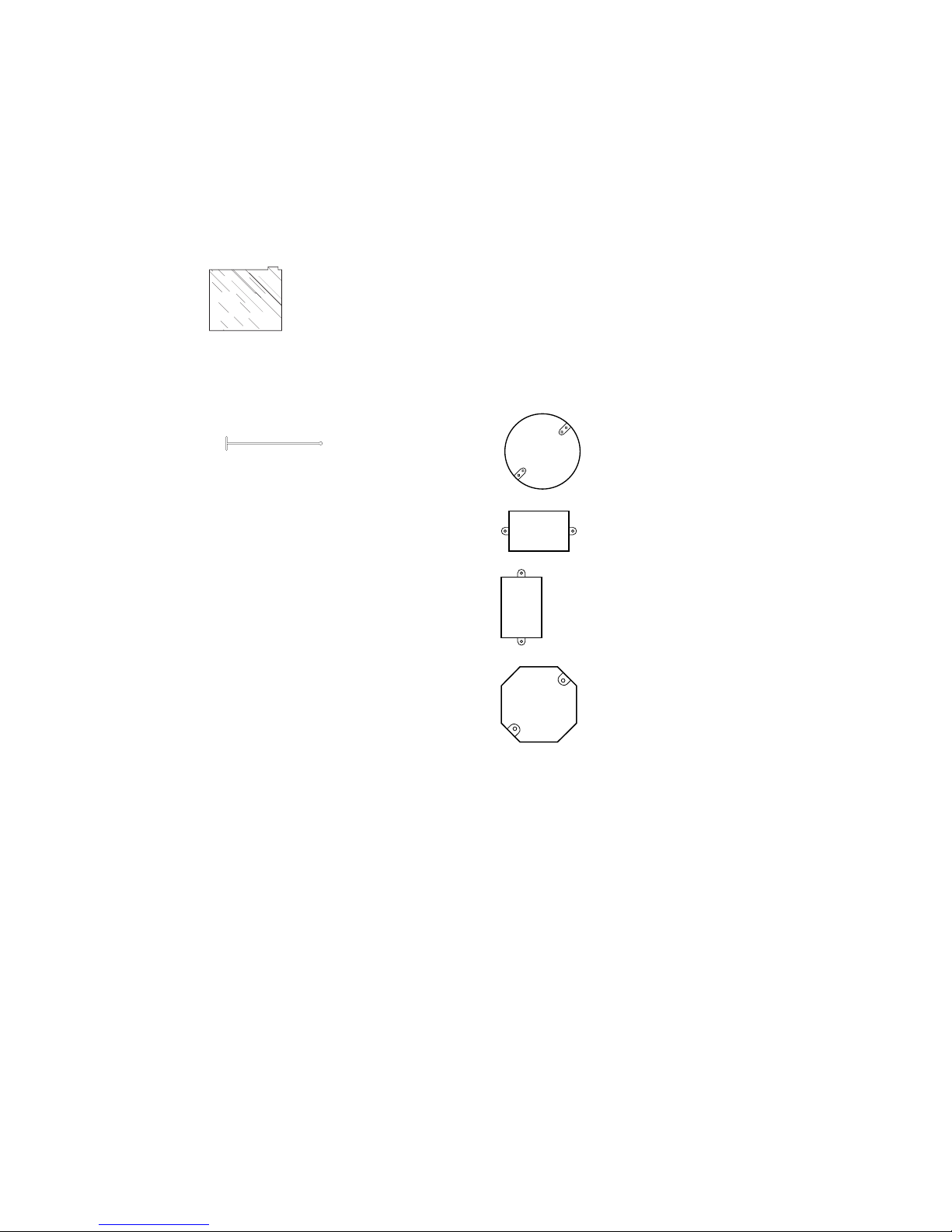
Package Contents
• Motion Sensor Light Fixture
• Lens shield
• Manual
• Hardware Pack
1 Gasket
1 Hanger
1Crossbar Mounting Bracket
4Wire Nuts
2 #6-32 X 3/4" Screws
(for small rectangular boxes)
2 #8-32 X 3/8" Screws
(for circular or octagon boxes)
2 #10-24 X 1/2" Screws
(for water tight boxes)
1 M5 X 0.8 X 40 mm Screw
(fixture to mounting bracket)
1 Rubber Plug
Additional Items Needed
• Phillips screwdriver
• Ladder
•2 Flood lamps, 150 Watts Maximum per lamp
Fits All Junction Box Configurations
Circular
Horizontal rectangular
Ve rtical rectangular
Octagon
Page 5
-5-
598-1118-04
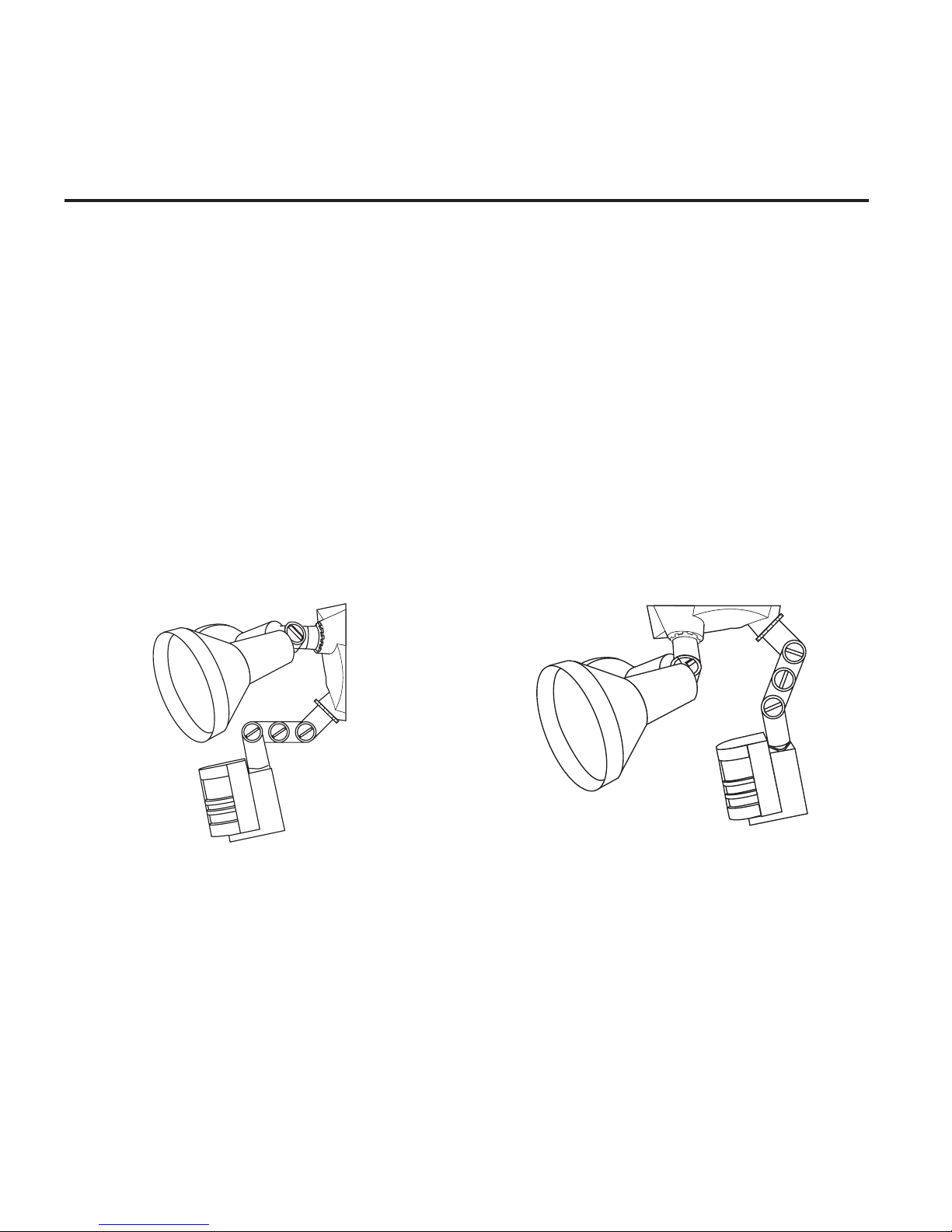
Installation
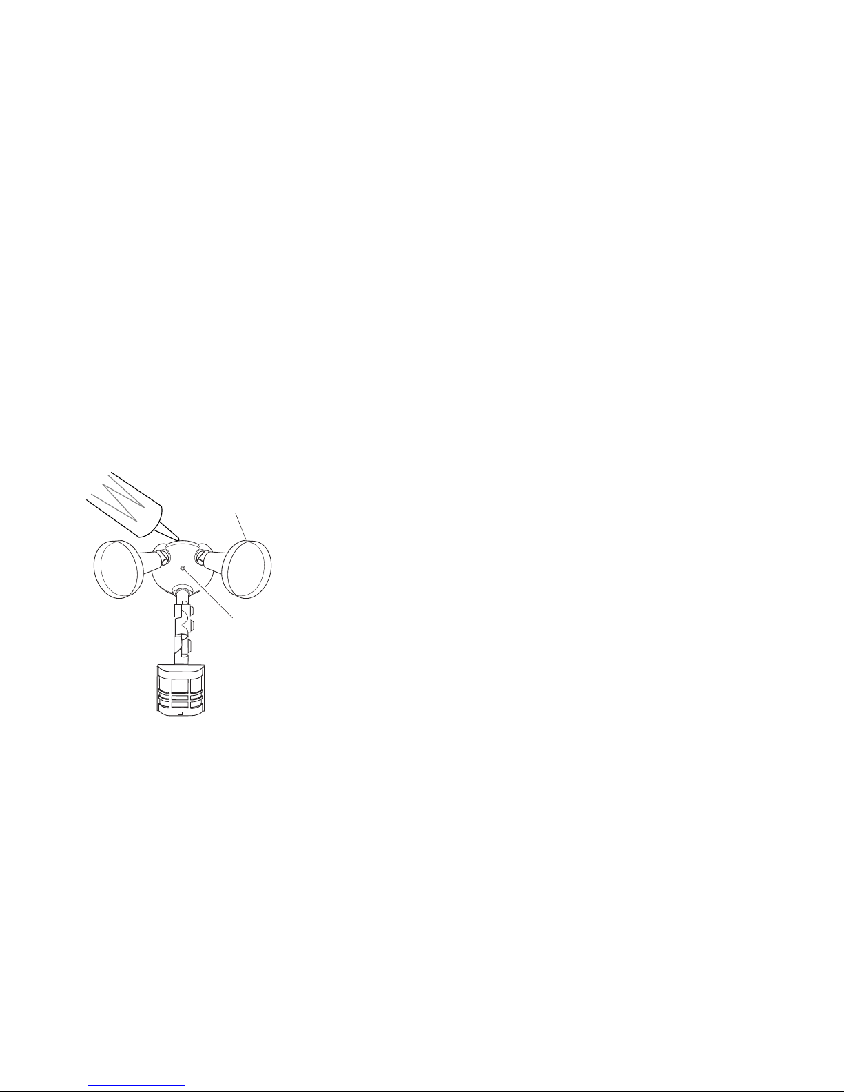
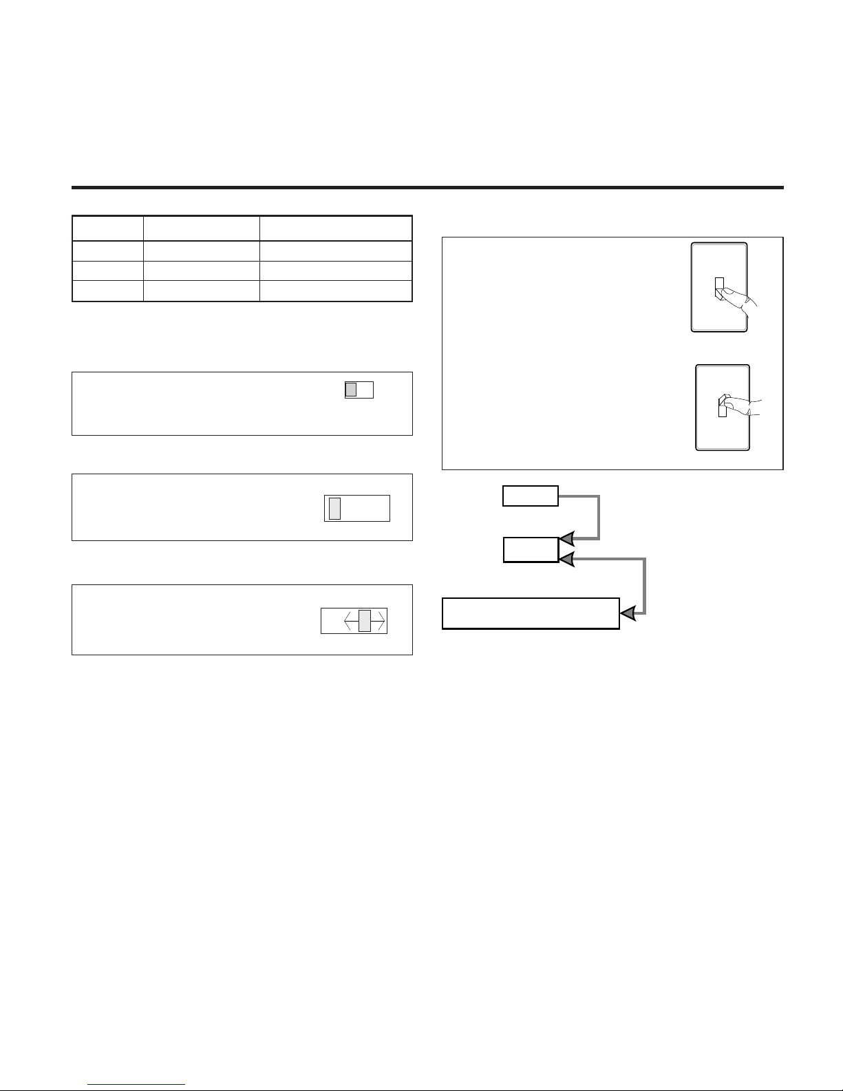
If you want to use the Manual Override feature you will need to install the fixture on a circuit controlled
by a switch.
❒ Loosen the thumbscrews holding the sensor
head and lampheads.
❒ Adjust the various parts so that the fixture
looks similar to this illustration.
❒ Finger tighten the thumbscrews at this time.
Wall Mount
Eave Mount
❒ Loosen the thumbscrews holding the sensor
head and lampheads.
❒ Adjust the various parts so that the fixture
looks similar to this illustration.
❒ Finger tighten the thumbscrews at this time.
CAUTION: BEFORE STARTING THE INSTALLATION, TURN THE POWER OFF AT THE
CIRCUIT BREAKER.
Page 6
-6-
598-1118-04
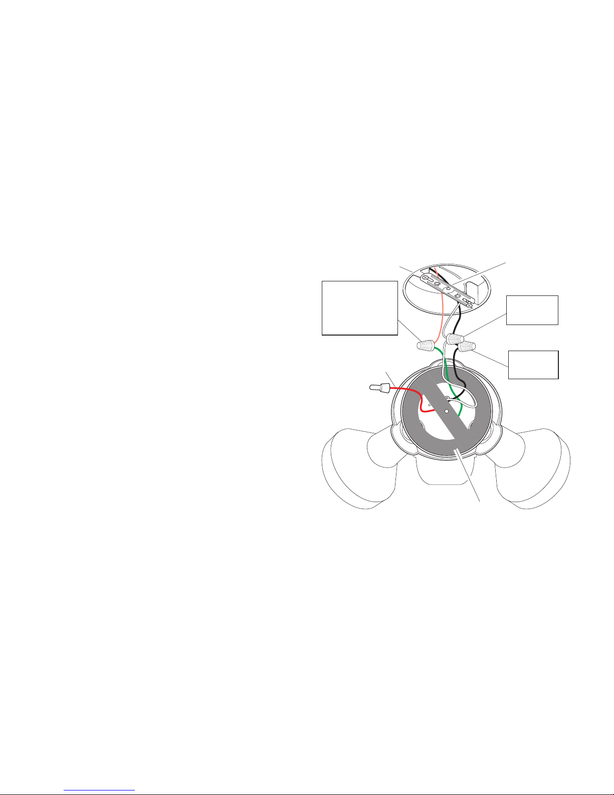
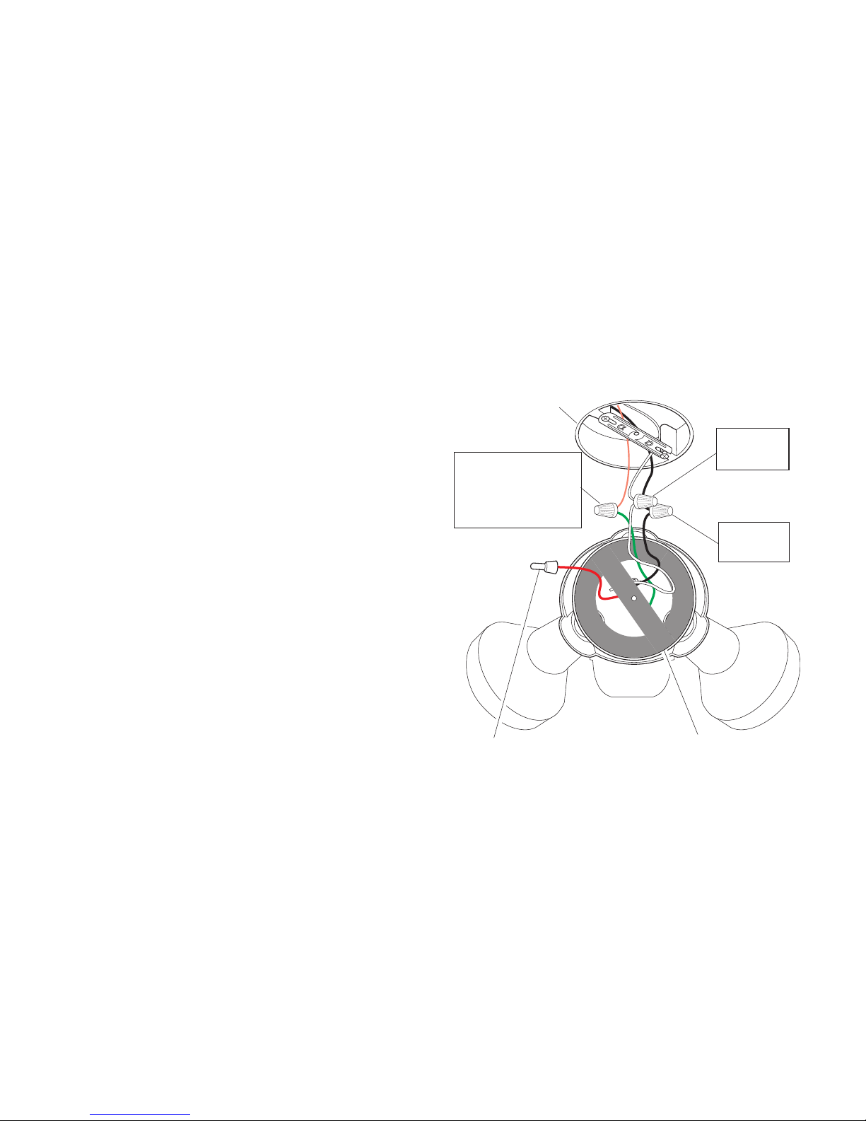
CAUTION: If you have not already turned the
power off at the breaker or fuse, do so now.
Connect the junction box wires to the fixture wires.
Twist together and secure with wire connectors.
CAUTION: If you are not controlling additional
fixtures from your JourneyMan
®
fixture, DO NOT
connect the RED wire.
Standard Wiring
Black to
Black
White to
White
Mounting
Bracket
Green ground
wire to
junction box
ground wire
RED, not
used in most
applications
Gasket
Mount Fixture with Crossbar
Mounting Bracket
❒ Tu rn power off at the fuse or circuit breaker.
❒ Remove the existing light fixture (if appli-
cable).
❒ Install the mounting bracket as shown using
two screws supplied in hardware pack that fit
your junction box:
Rectangular Junction Box - Use two #6-32
x 3/4" screws.
Circular or Octagonal Junction Box - Use
two #8-32 x 3/8" screws.
Watertight Junction Box - Use two #10-24
x 1/2" screws.
❒ The plastic hanger can be used to hold the fix-
ture while wiring. The small end of the plastic
hanger can be threaded through the hole in the
center of the cover plate. The small end then
goes into one of the slots on the mounting
bracket.
❒ Route the Light Control’s wires through the
large gasket holes.
Junction Box
Page 7
-7-
598-1118-04
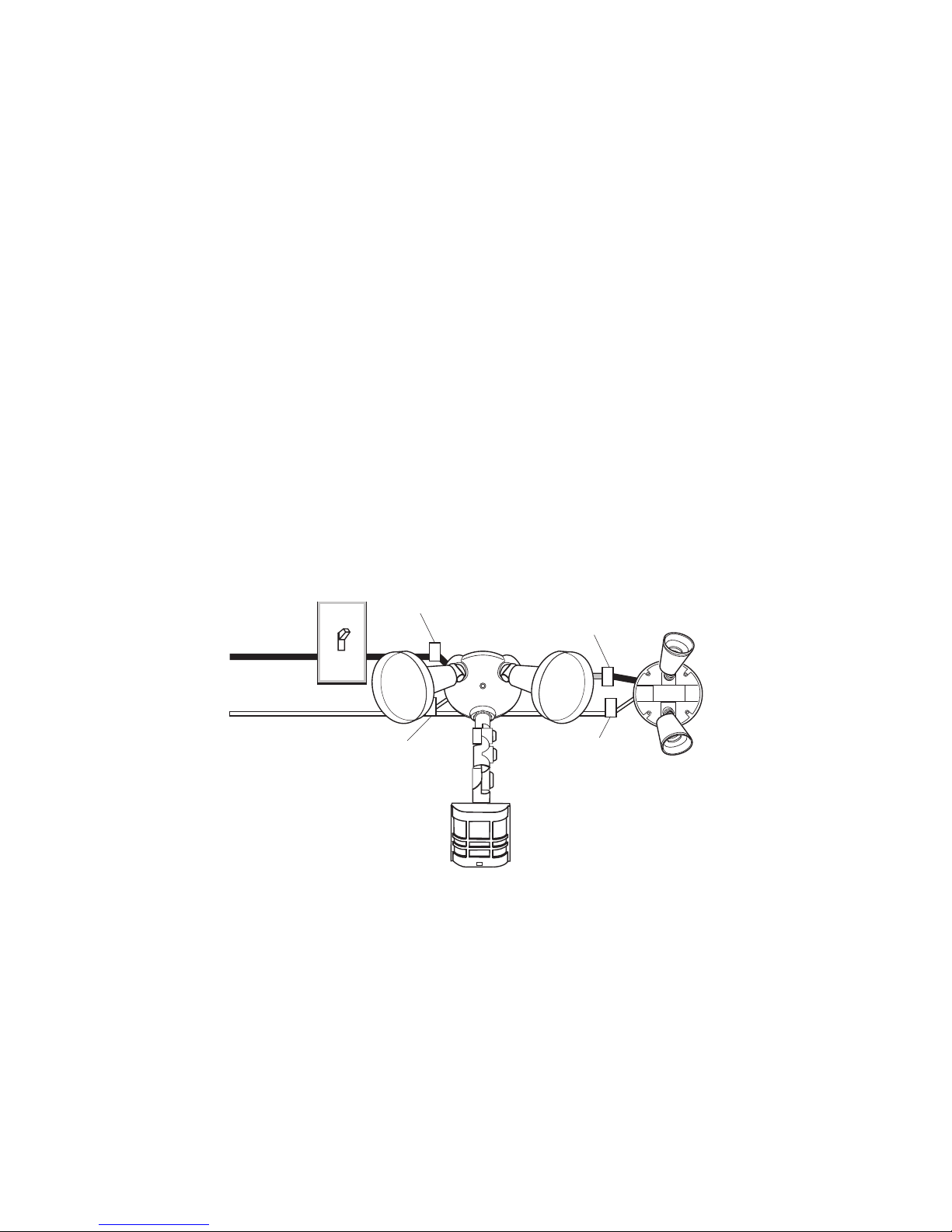
Controlling Non-Motion Sensing
Fixtures
❒ When wiring to additional standard fixture
only: Strip the motion sensor's red wire and
connect to the standard light's black wire.
Connect all white wires together. Total fixture
ratings must not exceed 1000 Watts (8.3 A).
NOTE: All wiring between fixtures should be run
in accordance with the National Electrical
Code through conduit or another acceptable
means. Contact a qualified electrician if
there is any question as to the suitability of
the system.
❒ This fixture is provided with a sensor rated
for 1000 Watts. Since the fixture is only rated
300 Watts, 700 Watts of additional load may
be controlled by this sensor.
❒ When determining what a fixture is rated for,
do not simply look at the rating on the lamp in
the fixture. Look at the marking which specifies the maximum lamp wattage for which the
fixture is suitable.
❒ Once you have selected the fixtures to be con-
nected and determined their maximum ratings,
add these ratings up. For instance, if you have
3 fixtures rated 100 Watts, 150 Watts, and 75
Watts respectively, you have a total load of 325
Watts.
(Standard)
RED from
JourneyMan® to
BLACK from
Fixture
BLACK from
Switch to
BLACK from
JourneyMan
®
Wiring to a Motion Light & Standard Fixture
WHITE from Line
to WHITE from
JourneyMan
®
WHITE from Line
to WHITE from
Fixture
Page 8
-8-
598-1118-04
Finish Mounting
❒ Align the JourneyMan
®
cover plate, gasket,
and the mounting bracket hole. Secure with
M5 x 0.8 x 40 mm mounting screw supplied.
❒ Push the rubber plug firmly into place.
❒ If not installed on a weatherproof box, caulk
between the cover plate and mounting surface with silicone weather sealant.
❒ Adjust the lamp holders by loosening the lock
nuts but do not rotate the lamp holders more
than 180° from the factory setting. When
screwing in the floodlamps, do not overtighten.
To avoid water damage and
electrical shock, keep lamp
holders aimed below horizontal.
Specifications
Range . . . . . . . . . . . . . . Up to 100 feet (30.5 m) with
Range Boost On; up to 70
feet (21 m) with Range
Boost Off. (Varies with sur-
rounding temperature).
Sensing Angle . . . . . . . . Up to 270°
Fixture Load . . . . . . . . . Up to 300 Watts Maximum
Incandescent [Up to 150
Watts maximum each lamp
holder.]
Sensor Load Capacity . . Up to 1000 Watts (8.3 amps),
Incandescent
Power Requirements . . . 120 VAC, 60 Hz
Operating Modes . . . . . . TEST, AUTO, and MANUAL
OVERRIDE
Time Delay . . . . . . . . . . 1, 5, 20 minutes
Sensitivity . . . . . . . . . . . Adjustable
Rubber Plug
DESA Specialty Products™ reserves the right to
discontinue products and to change specifications
at any time without incurring any obligation to incorporate new features in products previously sold.
Page 9
-9-
598-1118-04
Test and Adjustment
NOTES: When first turned on wait about 1 1/
2
minutes for the circuitry to calibrate.
Testing with Range Boost on during day-
light may result in abnormal operation.
Sensor Bottom
Do not aim the sensor at:
• Objects that change temperature rapidly, such
as heating vents and air conditioners, to help
avoid false triggering.
•Where pets or traffic may trigger the control.
• Nearby large, light-colored objects reflect-
ing light may trigger the shut-off feature. Do
not point other lights at the sensor.
❒ Tu rn on the circuit breaker and light switch.
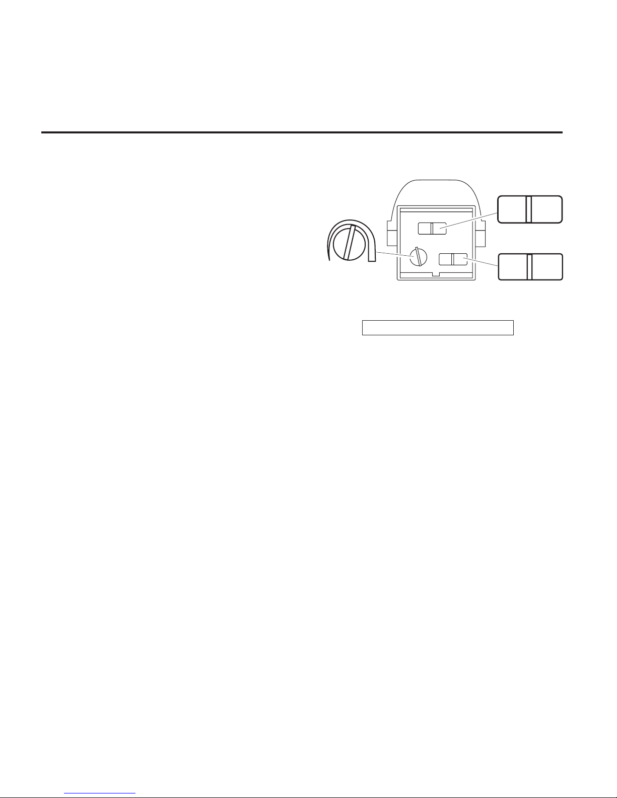
❒ Open the control access cover (on bottom
of unit) by pulling down on the tab of the
rubber cover.
❒ Turn the sensitivity control to the center of its
adjustment, RANGE BOOST to OFF and the
ON-TIME to TEST position.
MIN. MAX.
SENSITIVITY
Range Boost
OFF
ON
2
0
TEST 1 5
ON TIME
Page 10
-10-
598-1118-04
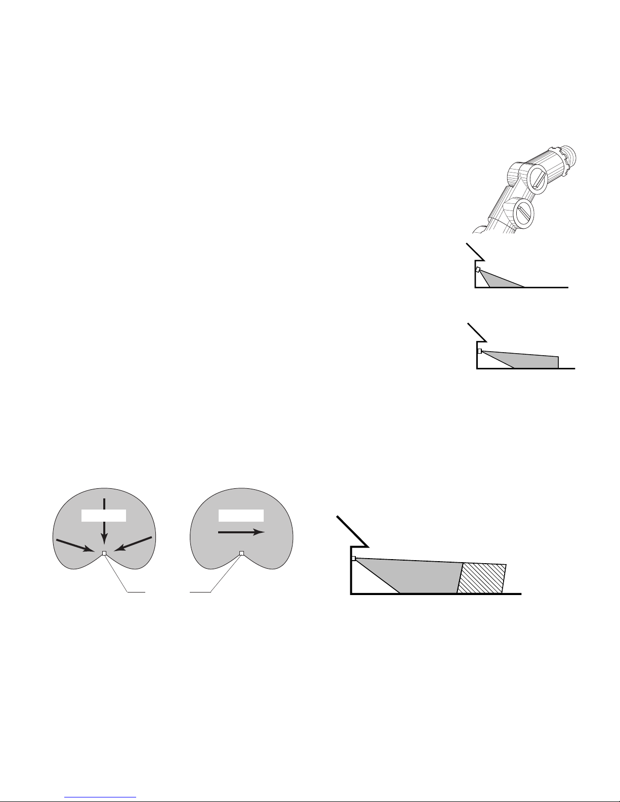
Adjustments Continued . . .
Aim Sensor Down
for Short Coverage
❒ Loosen the thumbscrews, estimate the direction to aim the sensor and tighten
the thumbscrews just enough to hold the sensor in place.
❒ Walk through the coverage area noting where you are when the lights turn
on. Loosen the thumbscrews and readjust the sensor as necessary. Tighten
the thumbscrews (finger tight) when you are satisfied with the coverage direction. Keep the sensor at least 1 inch (25 mm) from lamps and keep the
controls on the bottom.
❒ Adjust SENSITIVITY as needed to increase or decrease the range. Too much
sensitivity may cause false triggering.
❒ Set the amount of TIME (1, 5, or 20 minutes) you want the lights to stay on
after motion is detected at night.
❒ If you need to detect objects more than 70 feet (21 m) away, turn Range
Boost on. For maximum range, the sensor must be aiming straight out.
❒ Replace the rubber cover to protect controls.
Aim Sensor Out for
Long Coverage
Expected Coverage
The sensor is less sensitive to motion directly
towards it, most sensitive to motion across its
field of view.
When mounted 8 feet (2.4 m) from the ground, you
may expect the range shown below. If mounted much
higher the sensor may miss objects near the ground.
If mounted much lower the sensor range may be
reduced.
Sensor
Least Sensitive Most Sensitive
Motion Motion
Maximum Range
(Sensor aiming straight out)
8 ft.
(2.4 m)
70 ft. (21 m) 100 ft. (30,5 m)
(With Boost (With Boost On
Off and and Maximum
Maximum Sensitivity)
Sensitivity)
Page 11
-11-
598-1118-04
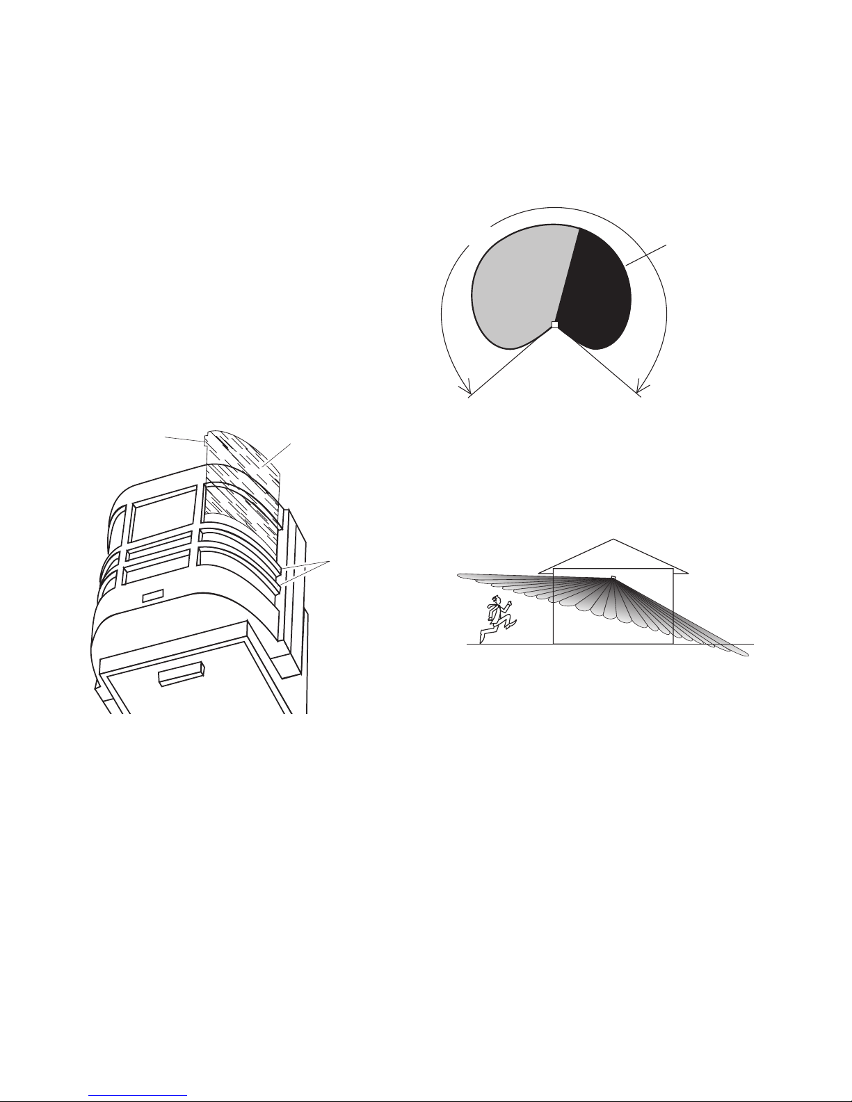
If the wide angle (270°) coverage is too wide for
your application, you may need to install the lens
shield to reduce the coverage angle.
❒ Decide which side of the lens you want to cover.
❒ Curve the shield as shown. Slide the shield
down, under the two metal ribs of the case.
Make sure the shield slides all the way down
so the entire shield will lay directly against
the lens.
❒ Slip the small protrusion behind the vertical
metal rib to hold the top of the shield in place.
Maximum
Coverage Angle
270°
Approx. area
blocked by the
lens shield (if
used)
Slip behind
vertical rib
Lens shield
Metal ribs
If the sensor is not kept level you may experience an apparent decrease in range because
objects may pass under the detection zone without being detected.
Page 12
-12-
598-1118-04
Operation
RANGE BOOST
Turn Range Boost on for additional coverage only if needed.
Off
On
Range Boost
TEST 1 5 20
ON TIME
TEST
AUTO
ON TIME
TEST 1 5 20
* resets to Auto Mode at dawn.
Mode: On-Time: Works: Day Night
Test 5 Sec x x
Auto 1, 5, or 20 min. x
Manual Until Dawn* x
MANUAL MODE
... back on.
1 Second OFF
then
...
Move ON-TIME Switch
to 1, 5, or 20 minutes
Flip light switch
off for one second
then back on*
* If you get confused while switching modes,
turn the power off for one minute, then back
on. After the calibration time, the control will
be in the AUTO mode.
MANUAL MODE
AUTO
TEST
Put the ON-TIME switch on the
sensor bottom in TEST and the
Range Boost switch to Off.
Put the ON-TIME switch in the
1, 5, or 20 minute position.
Manual Mode only works at
night because daylight returns
the sensor to AUTO.
Flip the light switch off for one
second then back on to toggle
between AUTO and MANUAL
MODE.
Manual Mode works with the
ON-TIME switch in the 1, 5,
or 20 minute position.
Page 13
-13-
598-1118-04
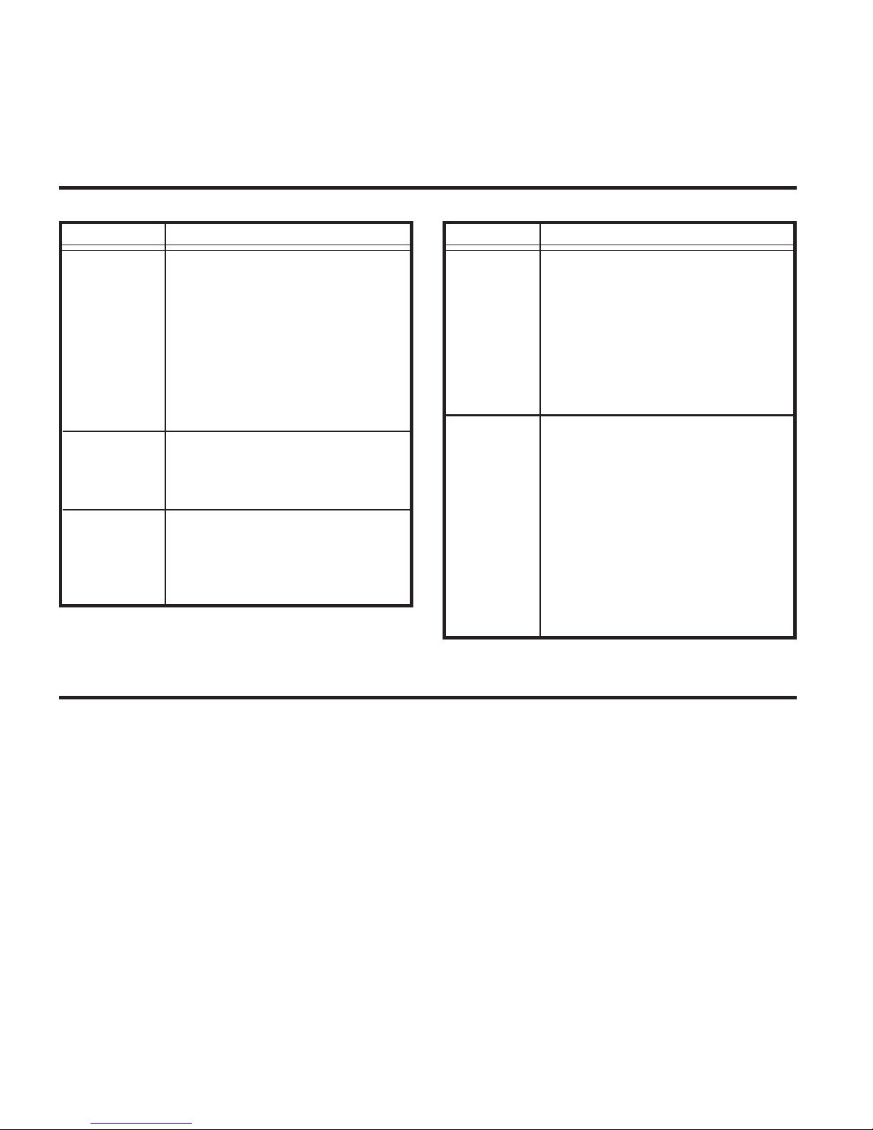
SYMPTOM
Lights will
not come
on.
Lights come
on in
daylight.
Lights come
on for no
apparent
reason.
SYMPTOM
Lights stay
on continuously.
Lights flash
on and off.
POSSIBLE CAUSE
1. A lamp is positioned too close to
the sensor or pointed at objects
that causes the sensor to trigger.
(Aim the lamp away from the sensor or objects).
2. Control is pointed at a heat source
like an air vent, dryer vent, or brightlypainted heat-reflective surface.
(Re-
aim sensor. Turn Boost off).
1. Heat or light from the lamps may be
turning the Light Control on and off.
(Aim lamps away from the sensor.
Turn Boost off)
.
2. Reflected heat from other objects
are triggering the sensor.
(Re-aim
sensor. Turn Boost off)
.
3. Control is warming up.
(Flashing is
normal under these conditions. Wait
1 minute for sensor to warm up)
.
4. Control is in Test.
(Set control switch
to an ON-TIME position)
.
POSSIBLE CAUSE
1. Light switch is turned off.
2. Flood light is loose or burned out.
3. Fuse is blown or circuit breaker is
turned off.
4. Daylight turnoff is in effect.
(Re-
check after dark)
.
5. Incorrect circuit wiring, if this is a
new installation.
6. Re-aim the sensor to cover desired area.
1. Control may be installed in a relatively dark location.
2. Control is in Test.
(Set control
switch to an ON-TIME position)
.
1. Control may be sensing small animals or automobile traffic.
(Re-
aim sensor or use lens shield)
.
2. Sensitivity is set too high.
(Reduce
sensitivity. Turn Range Boost off)
.
Troubleshooting Guide
Technical Service
Please call 1-800-858-8501 for assistance before returning product to store.
If you experience a problem, follow this guide. You may also want to visit our Web site at: www.desatech.com. If the
problem persists, call* for assistance at 1-800-858-8501, 7:30 AM to 4:30 PM CST (M-F). You may also write* to:
DESA Specialty Products™
P.O. Box 90004
Bowling Green, KY 42102-9004
ATTN: Technical Service Specialty Products
* If contacting Technical Service, please have the following information available: Model Number, Date of Purchase,
and Place of Purchase.
No Service Parts Available for this Product
Page 14

-14-
598-1118-04
JourneyMan® Lifetime Warranty
This is a “Limited Warranty” which gives you specific legal rights. You may also have other rights
which vary from state to state or province to province.
For as long as you (the original purchaser) own this JourneyMan® product, any malfunction caused
by factory defective parts or workmanship will be corrected at no charge to you. To obtain a refund
or a replacement, call 1-800-858-8501 for instructions.
Not Covered - Repair service, adjustment and calibration due to misuse, abuse or negligence,
light bulbs, batteries, and other expendable items are not covered by this warranty. Unauthorized
service or modification of the product or of any furnished component will void this warranty in its
entirety. This warranty does not include reimbursement for inconvenience, installation, setup time,
loss of use, unauthorized service, or return shipping charges.
This warranty covers only JourneyMan® products and is not extended to other equipment and
components that a customer uses in conjunction with our products.
THIS WARRANTY IS EXPRESSLY IN LIEU OF ALL OTHER WARRANTIES, EXPRESS OR IMPLIED, INCLUDING ANY WARRANTY, REPRESENTATION OR CONDITION OF MERCHANT ABILITY OR THAT THE PRODUCTS ARE FIT FOR ANY PARTICULAR PURPOSE OR USE, AND SPECIFICALLY IN LIEU OF ALL SPECIAL, INDIRECT, INCIDENTAL, OR CONSEQUENTIAL DAMAGES.
REPAIR OR REPLACEMENT SHALL BE THE SOLE REMEDY OF THE CUSTOMER AND THERE
SHALL BE NO LIABILITY ON THE PART OF DESA FOR ANY SPECIAL, INDIRECT, INCIDENTAL, OR CONSEQUENTIAL DAMAGES, INCLUDING BUT NOT LIMITED TO ANY LOSS OF
BUSINESS OR PROFITS, WHETHER OR NOT FORESEEABLE. Some states or provinces do
not allow the exclusion or limitation of incidental or consequential damages, so the above limitation
or exclusion may not apply to you. Proof of purchase is required for warranty claims.
Page 15

-15-
598-1118-04
CONTROL DE LUZ Y DETECTOR DE
MOVIMIENTO TODO HECHO DE METAL
Modelo HD-9250
© 2004 DESA Specialty Products™ 598-1118-04 S
Page 16

-16-
598-1118-04
Indice
Introducción ............................................................................................... 17
Contenidos del Paquete ........................................................................ 18
Instalación ...................................................................................................19
Montaje en pared .................................................................................. 19
Montaje en alero ....................................................................................19
Soporte de montaje de la barra de cruce ........................................... 20
Cableado Estándar .................................................................................20
Control de los aparatos que no detectan movimiento .......................21
Fin del Montaje...................................................................................... 22
Especificaciones ..................................................................................... 22
Prueba y Ajuste .......................................................................................... 23
Cobertura Esperada .............................................................................. 24
Funcionamiento ..........................................................................................26
Guia de Investigacion de Averias ..............................................................27
Garantía de por Vida del JourneyMan®................................................... 28
Page 17

-17-
598-1118-04
Introducción
Querido consumidor:
Deseamos agradecerle por haber comprado este producto JourneyMan®. Quienes trabajamos
para la Compañía DESA Specialty Products™ creemos que ha comprado el detector de movimiento
más durable que existe actualmente. Este producto JourneyMan® le ofrecerá un funcionamiento de por
vida. Tenemos tanta confianza en la durabilidad de este producto que lo respaldamos con una garantía
de por vida.
Características Mejoradas de Rendimiento
☞ Los dientes fuertes de sujeción y el tornillos de mano ofrecen un ajuste completo de las tres
dimensiones de la cabeza del detector.
☞ Los ocho empaques de caucho de silicona sellan los componentes y controles internos protegiéndolos
contra las condiciones ambientales severas.
☞ To rnillos de acero inoxidable para evitar el enmohecimiento y la corrosión.
☞ Protección incorporada de 1,25 mega vatios contra sobrecargas momentáneas.
☞ El diseño A.S.I.C. (Circuito Integrado de Aplicación Específica) permite un rendimiento más confiable.
☞ Opción de aumento de alcance para ampliar el alcance a aquellas áreas que son difíciles de cubrir.
☞ Cobertura de ángulo extremadamente grande (hasta 270˚).
☞ Fácil control de otras luces con su aparato JourneyMan® (hasta una carga total de 1000 vatios).
☞ El área ampliada de la placa translúcida recibe más luz infrarroja mejorando así su sensibilidad
de detección.
☞ La tecnología de cómputo de impulsos reduce una falsa detección, causada por el viento y la lluvia,
para obtener una confiabilidad profesional.
☞ La fotecélula automática desactiva la unidad durante el día para ahorrar energía.
☞ Restauración después de que se cortó la corriente. Apaga automáticamente las luces si se prenden
por interrupción de corriente o por una tormenta eléctrica.
☞ Temporizador de luz seleccionable para fijar el tiempo que la luz se quede prendida después de
detectar movimiento.
☞ El control de la sensibilidad permite el ajuste del alcance de cobertura.
☞ Sobrecontrol manual para prender/apagar las luces, a su conveniencia, con el interruptor de pared ya
existente dentro de casa.
Page 18

-18-
598-1118-04
Contenidos del Paquete
•Aparato de luz y detector de movimiento
• Protección de la placa translúcida
• Manual
•Paquete de ferretería
1 empaquetadura
1gancho
1 Soporte de montaje de la barra de cruce
4 conectores de cable
2 tornillos #6-32 x 3/4 pulgada.
(para cajas pequeñas rectangulares)
2 tornillos #8-32 x 3/8 pulgada.
(para cajas circulares u octagonales)
2 tornillos #10-24 x 1/2 pulgada.
(para cajas impermeables al agua)
1 tornillos M5 x 0.8 x 40 mm.
(desde el aparato al soporte de montaje)
1 Enchufe de caucho
Artículos adicionales que se
necesitan
• Destornillador Phillips
• Escalera
•2 reflectores, 150 vatios máximo por lámpara
Queda bien con todas las
configuraciones de cajas de empalmes
Circular
Rectangular horizontal
Rectangular vertical
Octagonal
Page 19

-19-
598-1118-04
Instalación
Si usted desea usar el sobrecontrol manual usted deberá instalar el aparato en un circuito controlado por
un interruptor.
❒ Afloje los tornillos de mano que sostienen el
cabezal del detector y los cabezales de lámpara.
❒ Ajuste las diferentes partes para que el
aparato se vea similar a esta ilustración.
❒ Ahora ajuste los tornillos de mano sólo con
los dedos.
Montaje en pared
Montaje en alero
❒ Afloje los tornillos de mano que sostienen el
cabezal del detector y los cabezales de lámpara.
❒ Ajuste las diferentes partes para que el aparato
se vea similar a esta ilustración.
❒ Ahora ajuste los tornillos de mano sólo con
los dedos.
CUIDADO: ANTES DE COMENZAR LA INSTALACION , APAGUE LA CORRIENTE EN EL
CORTACIRCUITOS.
Page 20
-20-
598-1118-04
CUIDADO: Si todavía no ha desconectado la
alimentación en el cortacircuito o fusible,
hágalo ahora.
Conecte los cables de la caja de empalmes a los
cables del aparato. Tuérzalos juntos y asegúrelos
con conectores de cable.
CUIDADO: Si no controlará aparatos adicionales
con su JourneyMan
®
, NO conecte el cable ROJO.
Cableado Estándar
Negro a
negro
Blanco a
blanco
Caja de
empalmes
ROJO, no usado en la
mayoría de las aplicaciones
Cable verde de a
tierra al cable de
a tierra de la caja
de empalme.
Empaquetadura
Instale el aparato con el soporte de
montaje de la barra de cruce
❒ Apague la energía en el fusible o
cortacircuitos.
❒ Quite el aparato de luz existente. (si es
aplicable).
❒ Instale el soporte de montaje como se
demuestra usando los dos tornillos provistos
en su paquete de ferreterÌa y que es apropiado
para su caja de empalme:
Caja de Empalme Rectangular - Use dos tornillos #6-32 x 3/4 pulgada.
Caja de Empalme Circular o Rectangular -
Use dos tornillos #8-32 x 3/8 pulgada.
Caja de Empalme impermeable - Use dos
tornillos #10-24 x 1/2 pulgada.
❒ Se puede usar el colgador plástico para
sostener el aparato mientras se instala el
cableado. El extremo pequeño del colgador se
puede pasar por el agujero en el centro de la
placa cubertora. El extremo pequeño va luego
dentro de las ranuras de la lámina de montaje.
❒ Pase todos los cables del aparato por los
agujeros grandes del empaque, como se
muestra.
Page 21

-21-
598-1118-04
Control de los aparatos que no
detectan movimiento
❒ En caso de conectar al aparato estándar
solamente: Pele el alambre rojo del detector
de movimiento y conéctelo al alambre negro
de la luz estándar. Conecte todos los alambres
blancos. La capacidad total no debe exceder
los 1000 Vatios (8,3 A).
NOTA: Todo el cableado de los aparatos debe ser
hecho de acuerdo al Código Eléctrico Nacional
por medio de conductos para cables u otras
formas aceptables. Póngase en contacto con
un electricista calificado si existe duda sobre
la aptitud del sistema.
❒ Este aparato viene con un detector con una
potencia de 1000 Vatios. Puesto que el aparato
tiene sólo una potencia de 300 Vatios, la carga
adicional de 700 Vatios puede ser controlada
por el detector.
❒ Cuando desee determinar la clasificación de
un aparato no vea tan sólo la potencia de la
lámpara. Mire la indicación que especifique
el voltaje máximo de la lámpara que el aparato
puede aceptar.
❒ Una vez que ha escogido los aparatos que se
conectarán y ha determinado sus máximas
potencias, súmelas. Por ejemplo, si tiene 3
aparatos de 100 , 150 y 75 Vatios
respectivamente, usted tendrá un total de
325Vatios.
(Estándar)
ROJO del JourneyMan
®
al NEGRO del aparato
NEGRO del conmutador al
NEGRO del JourneyMan
®
BLANCO de la línea al
BLANCO del JourneyMan
®
BLANCO de la línea al
BLANCO del aparato
Conexión a la luz de movimento y al aparato estándar
Page 22

-22-
598-1118-04
Fin del Montaje
❒ Alinee la placa cubertora JourneyMan
®
, la
empaquetadura y el agujero de montaje del
soporte. Asegúrelo con el tornillo de montaje
provisto M5 x 0.8 x 40 mm.
❒ Empuje el tapón de caucho firmemente hasta
que encaje.
❒ Si no lo instala sobre una caja protegida con-
tra la intemperie, calafatee entre la placa
cubertora y la superficie de montaje con un
sellador de silicona contra la intemperie.
❒ Ajuste los portalámparas aflojando las
contratuercas, pero no los gire más de 180° de
la calibración hecha en fábrica. Cuando
atornille los proyectores no los apriete
demasiado.
Especificaciones
Alcance . . . . . . . . . . . . . . . . . Hasta 100 pies (30,5 m)
con el Aumento de
Alcance [Range Boost]
prendido; hasta 70 pies
(21 m) con el Range
Boost apagado. (
varía
de acuerdo a la
temperatura que le
rodea
).
Angulo de detección . . . . . . . Hasta 270°
Carga del Aparato . . . . . . . . . Hasta 300 Vatios
máximo de luz
incandescente [hasta
150 Vatios máximo por
cada portalámparas].
Capacidad de
Carga
del Detector . . . . . . . . . . . . . Hasta 1000 Vatios (8,3
amps), Incandescente
Requisitos de Alimentación . 120 VCA, 60 Hz
Fases de Funcionamiento . . . PRUEBA, AUTO y
SOBRECONTROL
MANUAL
Retardo de Tiempo . . . . . . . . 1, 5, 20 minutos
Sensibilidad . . . . . . . . . . . . . Ajustable
Para evitar daños causados por el
agua y un choque eléctrico, mantenga
los portalámparas apuntando más
abajo de la línea horizontal.
Enchufe de caucho
DESA Specialty Products™ se reserva el derecho
de descontinuar productos y de cambiar
especificaciones a cualquier momento sin incurrir
en ninguna obligación de tener que incorporar
nuevas características en los productos vendidos con
anterioridad.
Page 23

-23-
598-1118-04
Prueba y Ajuste
NOTAS: Cuando lo prenda por primera vez
espere 1 1/
2
minutos hasta que el circuito
se calibre.
Las pruebas hechas durante el día con el
Aumento de Alcance [Range Boost]
prendido pueden resultar en un
funcionamiento anormal.
Fondo del Detector
Evite apuntar el detector hacia:
• Objetos que cambien rápidamente de
temperatura tales como ductos de calefacción
y acondicionadores de aire. Estas fuentes de
calor pueden causar falsas alarmas.
•Areas donde animales domésticos o el tráfico
puedan activar el control.
• Los objetos grandes cercanos y de colores
resplandecientes que reflejan la luz del día
pueden hacer que el detector se apague. No
apunte otras luces hacia el detector.
❒ Prenda el cortacircuitos y el interruptor
de luz.
❒ Abra la cubierta que da acceso al control (en
el fondo de la unidad) halando hacia abajo la
aleta de la cubierta de caucho.
❒ Gire el control de sensibilidad hacia el centro
de su ajuste, El RANGE BOOST hacia OFF
[apagado] y el ON-TIME a la posición de TEST.
MIN. MAX.
SENSITIVITY
Range Boost
OFF
ON
20TEST 1 5
ON TIME
Page 24

-24-
598-1118-04
❒ Afloje los tornillos de mano, juzgue la dirección para apuntar el detector y
ajuste los tornillos de mano tan sólo lo suficiente como para sostener el
detector en su sitio.
❒ Camine por el área de cobertura dándose cuenta dónde está cuando las
luces se prenden. Afloje los tornillos de mano y acomode de nuevo el detector como sea necesario. Ajuste los tornillos de mano (sólo con la mano)
cuando esté satisfecho con la dirección de la cobertura. Mantenga el de-
tector por lo menos a 1 pulgada (25 mm) de las lámparas y mantenga
los controles en el fondo.
❒ Ajuste la SENSIBILIDAD como lo necesite par aumentar o disminuir el
alcance. Demasiada sensibilidad puede ocasionar una falsa alarma.
❒ Fije el período de TIEMPO (1, 5 ó 20 minutos) que usted quiere que las
luces se queden prendidas después de detectar movimiento en la noche.
❒ Si necesita detectar objetos a más de 70 pies (21 m) de distancia, prenda
el Range Boost. Para lograr el alcance máximo, el detector debe estar
recto apuntando hacia afuera.
❒ Ponga de nuevo en su sitio la tapa de caucho para proteger los controles.
Continuación de ajustes . . .
Apunte el detector
más arriba para
mayor cobertura
Cobertura Esperada
El detector es menos sensible del movimiento que
se dirige hacia él.
Si lo instala a 8 pies (2,4 m) del suelo, usted puede
esperar el alcance que se muestra abajo. Si lo
instala mucho más arriba puede darse que el
aparato no detecte objetos cerca del suelo. Si lo
instala mucho más abajo, el alcance del detector
se puede reducir.
Apunte el detector
hacia abajo para
poca cobertura
Lo menos sensible Lo más sensible
Detector
Movimiento
Movimiento
2,4 m
(8 pies)
30,5 m
(100 pies)
(Con el aumento
encendido y la
sensibilidad máxima)
Alcance Máximo
(Detector recto y
apuntando hacia afuera)
21 m
(70 pies)
(Con el aumento apagado
y la sensibilidad máxima)
Page 25

-25-
598-1118-04
270°
Area aprox.
bloqueada por
la protección
de la placa
translúcida (si
se la usa)
Angulo de Cobertura
Máxima
Si la cobertura de ángulo grande (270°) es
demasiado ancha para su aplicación, usted puede
necesitar instalar la protección de la placa
translúcida para reducir el ángulo de cobertura.
❒ Decida qué lado de la placa translúcida
desea cubrir.
❒ Curve la protección como se muestra. Deslícela
hacia abajo, por debajo de los dos rebordes de
metal de la caja. Asegúrese de que la protección
se deslice completamente hacia abajo de manera
que toda ella se encuentre directamente asentada
sobre la placa translúcida.
❒ Deslice la pequeña saliente detrás del reborde
vertical de metal para sostener la protección
en su sitio.
Deslice detrás del
reborde de metal
Protección de la
placa translúcida
Rebordes
de metal
Si no mantiene el detector a nivel, usted puede
experimentar una aparente disminución de alcance
porque los objetos pueden pasar por debajo de la
zona de detección sin ser detectados.
Page 26

-26-
598-1118-04
Modalidad
:
A tiempo
:
Trabaja:Día Noche
Prueba
5 seg. x x
Autom.
1, 5 or 20 min. x
Manual
Hasta el
x
amanecer
*
Funcionamiento
AUMENTO DE ALCANCE
Off
On
Range Boost
PRUEBA
AUTOMATICO
ON TIME
TEST 1 5 20
* Se pone en Automático al amanecer.
Para MODO MANUAL
Apague el interruptor
por un segundo y
préndalo de nuevo*
TEST 1 5 20
ON TIME
...préndalo.
1 segundo
APAGADO
luego
...
Mueva el interruptor
de tiempo (ON-TIME)
a 1, 5 ó 20 minutos
Prenda el Aumento de Alcance
(Range Boost) para una cobertura
adicional sólo si lo necesita.
El modo manual funciona sólo por
la noche porque la luz del día pone
al detector en modo
AUTOMATICO .
Apague el interruptor por un
segundo y vuélvalo a prender.
El modo manual funciona sólo
cuando el interruptor de tiempo
(ON-TIME) está en la posición de
1, 5 ó 20 minutos.
* Si se confunde mientras cambia de fases, apague
la electricidad por un minuto y préndala de
nuevo. Después del tiempo de calibración el
control estará en fase AUTO(MATICA).
Colocar el conmutador de ONTIME del botón del sensor en
TEST y el conmutador de
Refuerzo de Alcance en Off.
Ponga el interruptor de tiempo
(ON-TIME) en la posición de
1, 5 ó 20 minutos.
PRUEBA
AUTOM.
MODO
MANUAL
Page 27

-27-
598-1118-04
SINTOMA
La luz no se
enciende.
La luz se
prende
durante el
día.
La luz se
prende sin
ninguna
razón
aparente.
POSIBLE CAUSA
1. El interruptor de luz está apagado.
2. El faro está flojo o fundido.
3. El fusible está quemado o el
cortacircuitos está apagado.
4. La desconexión de luz del día
está en efecto.
(Compruébelo al
anochecer)
.
5. Alambrado incorrectamente, si
ésta es una nueva instalación.
6. Apunte de nuevo el detector para
cubrir las áreas deseadas.
1. El Control de Luz puede estar
instalado en un lugar
relativamente oscuro.
2. El Control de Luz está en fase de
Prueba.
(Fije el interruptor del
control a la posición de TIEMPO)
.
1. El Control de Luz puede estar
detectando animales pequeños
o el trásito de automóviles.
(Reapunte el detector).
2. La Sensibilidad es demasiado
alta.
(Reduzca la sensibilidad).
Guia de Investigacion de Averias
SINTOMA
La luz se
queda
prendida
continuamente
.
La luz se
prende y se
apaga.
POSIBLE CAUSA
1. Un faro está colocado demasiado
cerca al detector o apunta a objetos
cercanos que hace que el calor
active el detector.
(Reposicione la
lámpara lejos del detector o de los
objetos cercanos).
2. El Control de Luz está apuntando
hacia una fuente de calor tal como
un conducto de aire, de secadora
o hacia una superficie con pintura
brillante y que refleja el calor.
(Reposicione el detector)
.
1. El calor o la luz de las lámparas
pueden estar prendiendo y
apagando el Control de Luz.
(Apunte las lámparas lejos del
detector. Apague el Boost)
.
2. El calor reflejado de otros objetos
están prendiendo la alarma del
detector.
(Apunte de nuevo el
detector. Apague el Boost)
.
3. El Control se está calentando.
(El prenderse y apagarse es
normal bajo estas condiciones.
Espere 1 minuto para que se
caliente el detector)
.
4. El Control está en fase de Test.
(Fije el interruptor del control a
una posición de ON-TIME)
.
Servicio Técnico
(No enviar los productos)
Si tiene algún problema por favor siga esta guía. Lo sentimos, pero no podemos contestar preguntas en español por
teléfono. Usted puede también escribir* a:
DESA Specialty Products™
P.O. Box 90004, Bowling Green, KY 42102-9004
* Si se llama al Servicio Técnico, por favor tener lista la siguiente información: Número de Modelo, Fecha de compra
y Lugar de compra.
No hay piezas de servicio disponibles para este producto
Page 28

-28-
598-1118-04
Garantía JourneyMan® Permanente
Esta es una “garantía limitada” que le da derechos legales específicos. Ud. puede también tener
otros derechos que varían de estado a estado o de provincia a provincia.
Por todo el tiempo que Ud. (el comprador original) posea este Producto Journey Man®, cualquier
funcionamiento anómalo ocasionado por partes o mano de obra defectuosas de fábrica será
corregido sin costo para Ud. Para obtener el reembolso o reemplazo, llame al 1-800-858-8501 y
pida instrucciones.
No Cubierto - Servicio de reparación, ajuste y calibración debido al mal uso, abuso o negligencia,
bombillas, baterías, u otras partes fungibles no están cubiertas por esta garantía. un servicio o
modificación no autorizados del producto o de cualquier componente que se provea, invalidarán
esta garantía en su totalidad. Esta garantía no incluye reembolso por inconveniencia, instalación,
tiempo de instalación, perdida de uso, servicio no autorizado, o costos de transporte de retorno.
Esta garantìa cubre sólo a productos JourneyMan® y no se extiende a otros equipos y componentes
que el cliente los usa junto con nuestros productos.
ESTA GARANTÍA ESTÁ EXPRESAMENTE EN LUGAR DE CUALQUIER OTRA GARANTÍA,
EXPRESADA O IMPLÍCITA, INCLUYENDO CUALQUIER GARANTÍA, REPRESENTACIÓN O
CONDICIÓN DE COMERCIABILIDAD O QUE EL PRODUCTO SEA ADAPTADO PARA
CUALQUIER PROPÓSITO O USO PARTICULAR, Y ESPECÍFICAMENTE EN LUGAR DE TODOS
LOS DAÑOS ESPECIALES, INDIRECTOS, INCIDENTALES O CONSECUENTES.
LA REPARACIÓN O EL REEMPLAZO SERÁN LAS ÚNICAS ALTERNATIVAS DEL CLIENTE Y
NO HABRÁ RESPONSABILIDAD POR PARTE DE DESA POR NINGÚN DAÑO ESPECIAL,
INDIRECTO, INCIDENTAL O CONSECUENTE, INCLUIDOS PERO NO LIMITADOS A PÊRDIDA
DEL NEGOCIO O DE LOS BENEFICIOS, SEAN O NO PREVISIBLES. Algunos estados o provincias
no permiten la exclusión o limitación de daños incidentales o consecuentes, de modo que la
limitación o exclusión arriba indicada pueda que no se aplique a Ud. Para reclamos por la garantía
se requiere la prueba de compra.
Page 29

-29-
598-1118-04
COMMANDE D’ÉCLAIRAGE TOUT MÉTAL À
DÉTECTEUR DE MOUVEMENT
Modèle HD-9250
© 2004 DESA Specialty Products™ 598-1118-04 F
Page 30

-30-
598-1118-04
Table des matières
Introduction ............................................................................................... 31
Contenu de l’emballage ........................................................................ 32
Installation ...................................................................................................33
Montage mural ...................................................................................... 33
Montage sous avant-toit ........................................................................33
Support d’installation de la barre ....................................................... 34
Câblage standard .................................................................................. 34
Commande d’appareils de commande
sans détecteur de mouvement..............................................................35
Finir le montage .....................................................................................36
Spécifications ..........................................................................................36
Test et réglage .............................................................................................37
Couverture prévue .................................................................................38
Fonctionnement ..........................................................................................40
Guide de dépannage .................................................................................. 41
Garantie à vie JourneyMan®..................................................................... 42
Page 31

-31-
598-1118-04
Introduction
Caractéristiques de performance améliorées
☞
Dents de serrage et vis à ailette robustes permettant un réglage tridimensionnel de la tête du détecteur.
☞ Huit garnitures d’étanchéité en caoutchouc silicone protègent les composants et les commandes
internes contre les conditions climatiques sévères.
☞ Les vis en acier inoxydable préviennent la rouille et la corrosion.
☞ Protection intégrée de 1,2 MW contre les surintensités.
☞ Concept A.S.I.C. (Application Specific Integrated Circuit) procurant une plus grande fiabilité.
☞ Intensificateur de détection optionnel pour étendre la couverture aux endroits difficiles à couvrir.
☞ Angle de couverture extrêmement grand (jusqu’à 270 ).
☞ Il est facile de commander d’autres appareils d’éclairage avec votre appareil JourneyMan
®
(jusqu’à
concurrence de 1000 W total).
☞ Lentille plus grande, donc plus grande sensibilité à la lumière infrarouge.
☞ Technologie à compte d’impulsions pour réduire les déclenchements intempestifs causés par la
pluie et le vent et assurer une fiabilité professionnelle.
☞ Cellule photoélectrique automatique mettant l’appareil hors tension le jour pour économiser l’énergie.
☞ Réenclenchement après panne de courant. Éteint l’éclairage automatiquement s’il est déclenché par
une panne de courant ou un orage électrique.
☞ Minuterie réglable pour déterminer la durée de fonctionnement de l’appareil d’éclairage après
détection d’un mouvement.
☞ Commande de la sensibilité : permet d’ajuster la plage de sensibilité.
☞ Priorité manuelle pour allumer/éteindre l’éclairage, à votre goût, au moyen d’un interrupteur mural intérieur.
Cher Consommateur:
Nous désirons vous remercier d’avoir acheté ce produit JourneyMan
®
. Nous de DESA Specialty
Products™ croyons que vous avez acheté le détecteur de mouvement le plus durable offert sur le marché
aujourd’hui. Ce produit JourneyMan® vous procurera un fonctionnement durable à vie. Nous avons une
telle confiance dans la durabilité de ce produit que nous l’accompagnons d’une garantie à vie.
Page 32

-32-
598-1118-04
Contenu de l’emballage
•Appareil d'éclairage à détecteur de mouvement
• Écran de lentille
• Manuel
• Ensemble de quincaillerie
1 Garniture
1 Crochet de suspension
1 Support d’installation de la barre
4 Serre-fils
2Vis #6-32 de 3/4 po
(pour petites boîtes rectangulaires)
2Vis #8-32 de 3/8 po
(pour boîtes rondes ou octogonales)
2Vis #10-24 de 1/2 po
(pour boîtes étanches à l’eau)
1Vis M5 x 0.8 x 40 mm
(appareil à support d’installation)
1
Bouchon de Caoutchouc
Articles additionnels requis
•Tournevis Phillips
• Échelle
•2 lampes-réflecteurs; 150 W max. par lampe
Convient à tous les types de boîte
de jonction
Ronde
Horizontale rectangulaire
Ve rticale rectangulaire
Octogonale
Page 33

-33-
598-1118-04
Installation
Si vous désirez utiliser la priorité manuelle, installez l’appareil sur un circuit commandé par un
interrupteur.a
❒ Desserrer les vis à ailette tout en soutenant la
tête du détecteur et les porte-lampes.
❒ Ajuster les différentes parties de manière que
l’appareil ait une apparence similaire à celle
de l’illustration.
❒ Serrer les vis à ailette avec les doigts à ce
moment-ci.
Montage mural
Montage sous avant-toit
❒ Desserrer les vis à ailette tout en soutenant la
tête du détecteur et les porte-lampes.
❒ Ajuster les différentes parties de manière que
l’appareil ait une apparence similaire à celle
de l’illustration.
❒ Serrer les vis à ailette avec les doigts à ce
moment-ci.
ATTENTION!: AVANT D’ENTREPRENDRE L’INSTALLATION, COUPER L’ALIMENTATION
AU DISJONCTEUR.
Page 34

-34-
598-1118-04
Noir à
noir
Blanc à
blanc
Boîte de jonction
Fil de terre Vert au
fil de terre de la
boîte de jonction
ROUGE, non
utilisé dans la
plupart des
applications
Garniture
AVERTISSEMENT: Si vous n’avez pas déjà
coupé l’alimentation électrique au disjoncteur ou
au fusible, faites-le maintenant.
Raccordez les fils de la boîte de jonction à ceux
de l’appareil. Torsadez-les ensemble et fixez-les
avec les serre-fils.
AVERTISSEMENT: Si vous ne commandez
pas d’auters appareils d’éclairage au moyen de
votre appareil JourneyMan
®
, NE BRANCHEZ
PAS le fil ROUGE.
Câblage standardInstaller le luminaire au moyen du
support d’installation de la barre,
s’il y a lieu.
❒ Couper l’alimentation du circuit
d’éclairage au fusible ou au disjoncteur.
❒ Enlever l’appareil d’éclairage existant. (le cas
échéant).
❒ Installer le support, tel qu’illustré, au moyen
des deux vis fournies avec la quincaillerie de
la boîte électrique :
Boîte électrique rectangulaire - Utilisez deux
vis n° 6-32 x 3/4 po.
Boîte électrique ronde ou octogonale -
Utilisez deux vis n° 8-32 x 3/8 po.
Boîte de connexion étanche - Utilisez deux
vis n° 10-24 x 1/2 po.
❒ Le crochet en plastique peut peut servir à sup-
porter le luminaire pendant le câblage. Le petit
bout du crochet en plastique peut être inséré
dans le trou au centre de la plaque de
couverture. Ensuite, le petit bout est inséré
dans une des fentes de la barre de montage.
❒ Faire passer les fils de la commande d'éclairage
par le trou de la garniture.
Page 35

-35-
598-1118-04
(Standard)
Commande d’appareils d’éclairage
sans détecteur de mouvement
❒ Pour le câblage à un seul appareil
d’éclairage additionnel: Dénudez le fil
rouge du détecteur et raccordez-le au fil
noir de l'appareil d'éclairage. La puissance
totale des appareils ne doit pas dépasser
1000W (8,3 A).
NOTE: Le câblage entre les appareils doit être
conforme aux exigences du Code National
d’électricité et monté dans un conduit ou d’une
autre façon acceptable. Si vous vous
demandez si le système est approprié,
consultez un électricien reconnu.
❒ Cet appareil est pourvu d’un détecteur d’une
puissance de 1000 W. Puisque la puissance de
l’appareil d’éclairage n’est que de 300 W, le
détecteur peut accepter une charge
additionnelle de 700 W.
❒ Lorsque vous voulez déterminer la capacité de
puissance d’un appareil, il ne suffit pas de lire
l’indication de puissance de l’ampoule.
Regardez plutôt l’étiquette qui indique la puissance maximale de l’appareil d’éclairage.
❒ Une fois que vous avez déterminé les appareils
à raccorder et leur puissance maximale,
additionnez ces puissances. Par exemple, si vous
utilisez 3 appareils de 100 W, 150 W et 75 W
respectivement, la charge totale sera de 325 W.
ROUGE de JourneyMan® à
NOIR du luminaire
NOIR de l'interrupteur à
NOIR de JourneyMan
®
BLANC de la ligne à
BLANC de JourneyMan
®
BLANC de la ligne à
BLANC du luminaire
Câblage à un appareil d’éclairage à détecteur de mouvement et à un appareil d’éclairage standard
Page 36

-36-
598-1118-04
Finir le montage
❒ Aligner la plaque du couvercle JourneyMan
®
et la garniture avec l’orifice du support de
montage. Fixer au moyen de la vis de montage M5 x 0.8 x 40 mm fournie.
❒ Poussez le bouchon de caoutchouc fermement
en place.
❒ Si l’installation n’est pas effectuée au moyen
d’une boîte de connexion étanche, appliquer
un produit d’étanchéité à base de silicon entre le couvercle et la surface d’installation.
❒ Ajuster les porte-lampes en desserrant les
écrous de blocage, mais ne pas faire tourner
les porte-lampes de plus de 180° par rapport
au réglage d’usine. Ne pas trop serrer les
lampes dans les porte-lampes.
Pour éviter les dommages dûs à
l’eau et les chocs électriques,
pointez les porte-lampe plus bas
que l’horizontale.
Spécifications
Portée . . . . . . . . . . . . Jusqu’à 30,5 m avec
l’intensificateur de
détection; jusqu’à 21 m
sans l’intensificateur de
détection. (Varie selon la
température ambiante).
Angle de détection . . Jusqu’à 270
Charge de l’appareil . Jusqu’à deux ampoules
incandescentes, pour un
maximum de 300 W
[maximum de 150 W par
support].
Capacité de charge
du détecteur . . . . . . . Jusqu’à 1000 W (8,3A),
incandescence
Alimentation . . . . . . . 120 VCA, 60 Hz
Modes de
fonctionnement . . . . . Essai, automatique et
priorité manuelle
Minuteries . . . . . . . . . 1 , 5 et 20 minutes
Sensibilité . . . . . . . . . Réglable
Bouchon de Caoutchouc
DESA Specialty Products™ se réserve le doit
d’abandonner tout produit et d’en changer les
spécifications, en tout temps et sans contracter
quelque obligation que ce soit quant à
l’incorporation de nouvelles caractéristiques aux
produits déjà vendus.
Page 37

-37-
598-1118-04
Test et réglage
NOTES: Après la mise en circuit, attendre environ
11/2 minute pour que les circuits
complètent leur étalonnage.
S’il est testé avec l’intensificateur de
détection pendant le jour, l’appareil
pourrait avoir un fonctionnement
anormal.
Dessous du détecteur
Ne pointez pas le détecteur en direction:
• D’objets dont la température change rapidement,
comme bouches de chaleur et climatiseurs,
pour prévenir les déclenchements intempestifs.
• D’endroits où les animaux domestiques ou la
circulation peuvent déclencher la commande.
• De grands objets de couleur pâle à proximité,
puisque la lumière réfléchie peut actionner le
dispositif de fermeture. Ne pointez pas d’autres
sources de lumière vers le détecteur.
❒ Mettez le disjoncteur et l’interrupteur
d’éclairage sous tension.
❒ Ouvrez le couvercle d’accès (dessous de
l’appareil) en tirant sur la patte du couvercle
en caoutchouc.
❒ Placez la commande de sensibilité au centre
de sa plage de réglage, RANGE BOOST à
OFF et ON-TIME à la position TEST.
MIN. MAX.
SENSITIVITY
Range Boost
OFF
ON
20TEST 1 5
ON TIME
Page 38

-38-
598-1118-04
Test et réglage (suite)
Pointez le détecteur vers
le bas pour une
couverture rapprochée
❒ Desserrez les vis à ailette, évaluez l’orientation du détecteur et resserrez
les vis à ailettes juste assez pour maintenir le détecteur en place.
❒ Marchez dans la zone de couverture et notez les endroits où vous vous
trouvez lorsque l’éclairage s’allume. Desserrez les vis à ailette et réorientez
le détecteur si nécessaire. Resserrez les vis à ailette (au doigt) lorsque
vous êtes satisfait de la couverture. Gardez le détecteur à au moins 25
mm des ampoules et gardez les commandes à la partie inférieure.
❒ Réglez la sensibilité (SENSITIVITY) au besoin pour augmenter ou
diminuer la portée. Une trop grande sensiblité pourrait entraîner des
déclenchements intempestifs.
❒ Réglez le temps d’éclairage (ON-TIME) à 1, 5 ou 20 minutes après
détection de mouvement la nuit.
❒ Si vous désirez que l’appareil détecte le mouvement au-delà de 21 m,
mettez l’intensificateur de détection sous tension. Pour une portée maximum, le détecteur doit être orienté presque parallèle au sol.
❒ Remettez le couvercle de caoutchouc en place pour protéger la commande.
Pointez le détecteur plus
haut pour une
couverture éloignée
Coverture prévue
Le détecteur est moins sensible au mouvement
dans sa direction qu’au mouvement croisant son
champ de vision.
Détecteur
Moins sensible Plus sensible
21 m
(Intensificateur de détection
hors tension et sensibilité au
maximum)
Portée maximale
(Détecteur presque
parallèle au sol)
Lorsque l’appareil est monté 2,4 m au-dessus du
niveau du sol, vous pouvez espérer la couverture
illustrée ci-dessous. S’il est monté beaucoup plus
haut, le détecteur peut manquer des objets situés
près du sol. Monté beaucoup plus bas, la portée
du détecteur pourrait être réduite.
2,4 m
Mouvement Mouvement
30,5 m
(Intensificateur
de détection
sous tension et
sensibilité au
maximum)
Page 39

-39-
598-1118-04
Si la couverture grand angle (270 ) est trop large
pour vos besoins, vous pouvez ajouter l’écran de
lentille pour réduire l’angle de couverture.
❒ Décidez de quel côté de la lentille vous
installerez l’écran.
❒ Recourbez l’écran comme illustré ci-dessous.
Glissez l’écran sous les deux nervures
métalliques du boîtier. Assurez-vous que
l’écran glisse jusqu’au fond pour qu’il soit
complètement au contact de la lentille.
❒ Glissez la petite saillie de l’écran derrière la
nervure métallique verticale pour maintenir le
dessus de l’écran en place.
Angle de couverture
maximum
270°
Aire approximative bloquée par
l’écran de la
lentille (le cas
échéant)
Glissez derrière la
nervure métallique
verticale
Écran de lentille
Nervures
métalliques
Si le détecteur n’est pas conservé de niveau, vous
pourriez remarquer une diminution de la portée
puisque les objets pourraient passer sous la zone
de détection sans être détectés.
Page 40

-40-
598-1118-04
PRIORITÉ MANUELLE
AUTO
TEST
Fonctionnement
INTENSIFICATEUR DE DÉTECTION
Activez l’intensificateur de
détection pour augmenter la
couverture seulement si nécessaire.
Off
On
Range Boost
TEST 1 5 20
ON TIME
TEST
AUTO
ON TIME
TEST 1 5 20
* Se remet en mode Auto à l’aube.
PRIORITÉ MANUELLE
...remise sous
tension.
1 seconde hors
tension
puis
...
Placez l’interrupteur ON-
TIME à 1,5 ou 20 minutes
Mettre l’interrupteur
hors circuit pendant
une seconde, puis le
remettre en circuit*
* Si vous ne savez plus dans quel mode se trouve
l’appareil, couper l’alimentation pendant une minute
puis la rétablir. Après le temps d’étalonnage, la
commande reviendra au mode AUTO.
Placez l’interrupteur ON-TIME
(temps en circuit) du dessous
du détecteur à la position
TEST et la commande de
l’intensificateur de détection (Range
Boost), à la position hors circuit (Off).
Placez l’interrupteur ON-TIME
à la position 1, 5 ou 20 minutes.
Le mode manuel ne fonctionne
que la nuit parce que la lumière du
jour remet le capteur en mode
AUTO.
Mettre l’interrupteur hors circuit
pendant une seconde, plus en circuit pour alterner entre les modes
AUTO et MANUEL.
Le mode manuel ne fonctionne
que lorsque l’interrupteur ONTIME est aux positions 1, 5 ou 20.
Mode
: Temps en circuit: Fonctionne:Jour Nuit
Essal 5 secondes x x
Auto
1, 5 or 20 min. x
Manuel Jusqu’à l’aube* x
Page 41

-41-
598-1118-04
SYMPTÔME
L’éclairage
demeure
allumé
continuellement
.
L’ éclairage
clignote
CAUSE POSSIBLE
1. Une lampe est située trop près du
détecteur ou pointée vers des
objets qui déclenchent le détecteur.
(Réorientez la lampe loin du
détecteur ou des objets).
2. La commande est pointée vers
une source de chaleur comme un
évent, une sortie de sécheuse, ou
une surface claire qui réfléchit la
chaleur.
(Réorientez le détecteur
ou utilisez l’écran de lentille).
1. La chaleur ou l’éclairage des
lampes peut éteindre et allumer la
commande d’éclairage.
(Orientez
les lampes loin du détecteur ou
des objets. Mettez l’intensificateur
de détection hors tension).
2. La chaleur réfléchie par les objets
environnants déclenche le
détecteur.
(Réorientez le détecteur
ou utilisez l’écran de lentille).
3. La commande se réchauffe.
(Le
clignotement est normal dans ces
conditions. Laissez le détecteur se
réchauffer pendant 1 minute)
.
4. La commande est en mode Test.
(Placez l’interrupteur de la
commande à une position ONTIME)
.
SYMPTÔME
L’éclairage
ne s’allume
pas.
L’éclairage
s’allume en
plein jour.
L’éclairage
s'allume
sans raison
apparente.
CAUSE POSSIBLE
1. L’interrupteur d’éclairage est hors
tension.
2. Le projecteur es dévissé ou brûlé.
3. Le fusible a sauté ou le disjoncteur
a été déclenché
4. Le dispositif de coupure pendant
le jour fonctionne.
(Vérifiez à
nouveau à la noirceur).
5. Mauvais câblage du circuit, dans
le cas d’une nouvelle installation.
6. Réorientez le détecteur pour
couvrir l’aire désirée.
1. La commande peut être installèe
dans un endroit relativement
sombre.
2. La commande est en mode test.
(Placez l’interrupteur de la
commande à une position ONTIME).
1. La commande peut détecter de
petits animaux ou la circulation
automobile.
(Réorientez le
détecteur ou utilisez l'écran de
lentille
).
2. Le réglage de sensibilité est trop
élevé.
(Réduisez la sensibilité.
Mettez l'intensificateur de
détection hors tension)
.
Guide de dépannage
Service Technique
(N'envoyez pas de produits)
Si vous éprouvez des difficultés, suivez ce guide. Vous pouvez également écrire à l'adresse suivante :
DESA Specialty Products™
P.O. Box 90004, Bowling Green, KY 42102-9004
* Lors d’un appel au service technique, veuillez avoir les renseignements suivants à portée de main : numéro du modèle,
date d’achat et endroit de l’achat.
Aucune pièce de rechange n’est disponible pour ce produit
Page 42

-42-
598-1118-04
Garantie à vie JourneyMan
®
Il s’agit d’une « Garantie limitée » qui vous confère des droits juridiques spécifiques. Vous pouvez
également jouir d’autres droits, variables d’une province à l’autre.
Tant et aussi longtemps que vous (l’acheteur initial) possédez ce produit JourneyMan®, toute
anomalie de fonctionnement imputable à un vice de matériau ou de main-d’oeuvre sera corrigée
gratuitement. Pour obtenir un remboursement ou un remplacement, composez le 1-800-858-8501
pour obtenir des instructions.
Exclusions de la garantie - Réparations, réglage et calibrage dus à une mauvaise utilisation, un
mauvais traitement ou à la négligence. Les ampoules, les piles et des autres articles non durables
ne sont pas couverts par cette garantie. Le service non autorisé ou la modification du produit ou
d’un ou l’autre de ses composants fournis invalidera totalement la présente garantie. Cette garantie
n'inclut pas le remboursement pour le dérangement, l'installation, le réglage, la perte d'utilisation,
le service non autorisé ou les frais d'expédition pour le renvoi de la marchandise.
La garantie ne couvre que les produits JourneyMan® et ne s’étend pas aux autres équipements et
composants que le client pourrait utiliser conjointement avec nos produits.
CETTE GARANTIE TIENT EXPRESSÉMENT LIEU DE TOUTES AUTRES GARANTIES, EXPLICITES
OU IMPLICITES, Y COMPRIS DE TOUTE GARANTIE DE REPRÉSENTATION OU DE CONDITION
DE CONVENANCE À LA COMMERCIALISATION OU À L’EFFET QUE LES PRODUITS
CONVIENNENT À UN BUT OU À UNE UTILISATION PARTICULIÈRE, ET SPÉCIFIQUEMENT DE
TOUS DOMMAGES SPÉCIAUX, DIRECTS, INDIRECTS OU SECONDAIRES.
LE REMPLACEMENT OU LA RÉPARATION CONSTITUENT LE SEUL RECOURS DU CLIENT
ET DESA NE POURRA ÊTRE TENUE RESPONSABLE DE TOUS DOMMAGES SPÉCIAUX, DIRECTS, INDIRECTS OU SECONDAIRES, Y COMPRIS, SANS S’Y LIMITER, LES PERTES
COMMERCIALES ET PERTES DE PROFIT, QU’ELLES SOIENT PRÉVISIBLES OU NON.
Certaines provinces n’autorisent pas l’exclusion ou la limitation des dommages indirects ou
secondaires, et la limitation ou l’exclusion ci-dessus pourrait ne pas s’appliquer à vous. Pour toute
réclamation en vertu de la garantie, il est nécessaire de présenter une preuve d'achat.
 Loading...