

Page 1
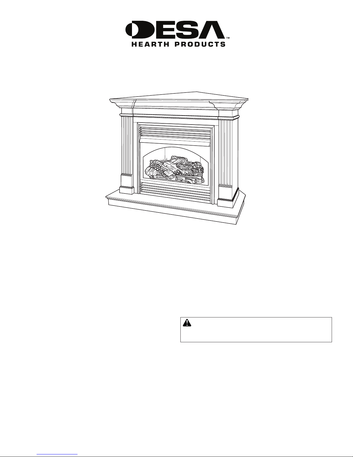
C32CO Corner Mantel and Base
ASSEMBLY AND INSTALLATION INSTRUCTIONS
IMPORTANT: Read entire instruction sheet before
assembling or installing mantel kit.
These mantels are only approved for use with any
DESA Heating, LLC 32" electric and gas replace system. Do not use mantel with any other product.
This mantel kit contains the following:
• Mantel pieces - unassembled and numbered as follows:
#1 Base
#2 Right Side Assembly
#4 Left Side Assembly
#4 Header
#5 Top
#6 Top Triangle
#7 Top Left Support
#8 Top Right Support
#9 Top Center Support
#10 Base Support
#11 Vertical Support
Right Top Trim Strip
Left Top Trim Strip
• Hardware Package
36 - 1 1/4" Wood Screws 114325-01
8 - 1" Finishing Nails 114295-01
4 - 2" Wood Screws 122447-01
* Extra hardware may be included
Tools required:
• Power Screwdriver with #2 Phillips Bit
• Hammer
• Nail Set
If any wood pieces are missing or damaged, contact the
dealer where you purchased this mantel for replacement. If
hardware is missing or damaged, contact DESA Heating, LLC
at 1-866-672-6040 for referral information. You can also visit
DESA Heating, LLC’s web site at www.desatech.com.
Note: Gather all mantel pieces together before assembling
mantel.
WARNING: Only use 1 1/4" screws to assemble
mantel. Damage to mantel will result if other screws
are used for this purpose.
www.desatech.com
Page 2

ASSEMBLING MANTEL
IMPORTANT: More than one person is required to lift
assembled mantel. Lift mantel by leg assemblies. Lifting
by header or mantel top could damage mantel.
Use the following illustrations to assemble mantel. Use only
screws provided.
11/4" Screws
Base #1
Base Support #10
Figure 1 - Installing Base Support
Header #4
Right Leg
Assembly #2
Base #1
Figure 3 - Installing Mantel Base
11/4"
Screws
Left Leg
Assembly #3
IMPORTANT: Align mantel left to right on base before installing. Corner of mantel legs must be ush with back of mantel
base before installation (see Figure 5, page 3). Use a tape
measure to insure accuracy.
2" Screws
Top Center
Support #9
Right Leg
Assembly #2
Header
Assembly
Block
11/4"
Screws
Left Leg
Assembly #3
Figure 2 - Installing Header
Header into
Groove on
Legs
Mantel Top #5
11/4" Screws
Top Left
Support #8
Figure 4 - Mantel Top Assembly
Top Triangle #6
Top Right
Support #8
IMPORTANT: Use 2" screws only on top center support. Using 2" screws in any other location will damage
mantel.
2
www.desatech.com
123754-01A
Page 3

Assembly
Blocks
11/4"
Screws
Figure 5 - Installing Mantel Top
Mantel Top
Assembly
Assembly
Blocks
Corner
of Mantel
Legs Must
be Flush
with Edge
of Mantel
Top (Both
Sides)
Mantel
Legs Flush
with Mantel
Base
Fireplace Installation
1. Fireplace should be fully assembled. See Assembling
Fireplace in replace owner’s manual.
2. Mantel must be installed ush with two walls. Remove
baseboard along walls where mantel is to be installed.
Baseboard will prevent proper installation of mantel and
base.
3. Place mantel base close to installation location. See replace owner’s manual for installation clearances. Leave
enough room to insert replace from back of mantel.
4. If installing gas replace, install gas line. See Connecting
to Gas Supply in replace owner’s manual. Remember to
leave access to gas shutoff valve somewhere on mantel
base or where it is accessible to user. Check for leaks.
See Checking Gas Connections in replace owner’s
manual.
5. Position replace inside mantel through back opening
(see Figure 6). Carefully position gas lines if applicable.
IMPORTANT: Use caution when positioning replace on
base. Base may scratch easily. Make sure replace is in
proper position within mantel opening before continuing
with installation.
6. Gas replace with louver door: Lower bottom louver
door. Use two screws provided in replace hardware kit
and attach replace to wooden base. Close louver door.
Gas replace with xed louver: Before installing logs
or burner assembly (see owner’s manual) remove screws
securing oor to assembly. Lift oor for access to bottom of replace. Use two screws provided in replace
hardware kit and attach replace base to wooden base.
Reinstall oor with screws removed previously.
IMPORTANT: Align mantel top left to right before installing.
Back corner of mantel leg must be ush with edge of mantel
top before installation.
IMPORTANT: If installing a gas replace, vertical support
will be installed to mantel assembly after gas replace has
been installed. If installing electric replace, rst install vertical support and install replace from front of mantel. Do not
put any weight on mantel top until vertical support has been
installed.
Figure 6 - Installing Gas Fireplace
123754-01A
www.desatech.com
3
Page 4

Electric Fireplace Installation
123754 01
This mantel can be used with DESA Heating, LLC electric
replaces. Electric replaces install from the front of mantel.
To install electric replace see replace instruction manual.
Vertical Support Installation
Install vertical support (see Figure 7).
Top
Center
Support
Vertical
Support
#11
1 1/4" Screws
MANTEL INSTALLATION
1. Carefully push mantel and base into position in corner
and ush against both walls. Check operation of replace
before proceeding.
2. Place right trim strip on right side of top and left trim on left
side of top. Align both pieces so any gaps between mantel
and wall are covered as well as possible and front of trim
strips are ush with side of top. With one person holding
trim strips in place, nail each strip to mantle using nishing
nails included in hardware kit and nail set.
Finishing Nails
Trim Strips
Figure 8 - Installing Mantel Trim
Base Support #10
Figure 7 - Installing Vertical Support
1 1/4" Screws
DESA Heating, LLC
2701 Industrial Drive
Bowling Green, KY 42101
www.desatech.com
1-866-672-6040
NOT A UPC
123754-01
Rev. A
04/08
 Loading...