

Page 1

WORKSHOP MANUAL
GP1 125-250 c.c.
Page 2

DERBI - NACIONAL MOTOR, S.A.U., manufacturer of DERBI motorcycles and mopeds, has produced this
manual with the aim of documenting and simplifying as much as possible the work you need to do to in dismantling and assembling the GP1 125/250 c.c.
The intention is to provide as much assistance as possible to mechanics working for our brand’s dealers and
sub-dealers.
Due to its constant commitment to improving its products, DERBI - NACIONAL MOTOR, S.A.U. Sociedad
Unipersonal reserves the right to introduce any modifications it deems fit, without prior warning.
All the information included in this manual is based on the latest data available at the time of its publication.
The drawings and photographs in this manual are for reference purposes only, and may therefore not be
exactly the same as the corresponding parts of the current model itself.
NACIONAL MOTOR, S.A.U.
1
Page 3

Page 4

INTRODUCTION
GENERAL INFORMATION
GENERAL TECHNICAL DATA
RECOMMENDED TOOLS
PERIODIC MAINTENANCE
DISMANTLING
SEAT SIDE TRIM
COWLING
COWLING BOTTOM COVER
WATER-OIL TANK COVER
SIDE COVERS
SHIELD INNER COVER
BATTERY COVER
PETROL TANK COVER
HELMET CARRIER
FOOTRESTS
SIDE COVERS
SHIELD
ENGINE
EXHAUST ASSY - REMOVAL
REMOVAL OF THE WNGINE FROM THE VEHICLE
AUTOMATIC TRANSMISSION
AIR DUCT
REMOVING THE DRIVEN PULLEY SHOFT BEARING
REFFITING THE DRIVEN PULLEY SHOFT BEARING
BAFFLE ROLLER
REMOVING THE DRIVEN PULLEY
INSTEPTING THE CLUTCH DRUM
REMOVING THE CLUTCH
INSPECTING THE CLUTCH
PIN RETAINING COLLAR
REMOVING THE DRIVEN HALF-PULLEY BEARING
INSPECTING THE DRIVEN FIRED HALF-PULLEY
INSPECTING THE DRIVEN SUDING HALF-PULLEY
REFITTING THE DRIVEN HALF-PULLEY BEARING
REFITTING THE DRIVEN PULLEY
INSPECTING THE CLUTCH SPRING
Pág. 1
Pág. 8
Pág. 9
Pág. 30
Pág. 40
Pág. 64
Pág. 64
Pàg. 65
Pág. 65
Pág. 65
Pág. 66
Pág. 66
Pág. 66
Pág. 67
Pág. 68
Pág. 68
Pág. 68
Pág. 69
Pág. 69
Pág. 71
Pág. 71
Pág. 72
Pág. 72
Pág. 73
Pág. 73
Pág. 73
Pág. 74
Pág. 76
Pág. 76
Pág. 77
Pág. 77
Pág. 78
Pág. 78
Pág. 80
Pág. 81
3
Page 5

REFITTING THE CLUTCH
REFITTING THE DRIVEN PULLEY
DRIVE-VELT
REMOVING THE DRIVING PULLEY
INSPECTING THE ROLLERS CASE
REFTTING THE DRIVING PULLEY
REFITTING THE TRANSMISSION COVER
Pág. 82
Pág. 85
Pàg. 85
Pág. 86
Pág. 87
Pág. 88
Pág. 89
END GEAR
REMOVING THE WHEEL AXLE
REMOVING THE HUB BEARING
REMOVING THE WHEEL ASXLE BEARING
REMOVING THE DRIVEN PULLEY SHAFT BEARING
INSPECTING THE HUB SHAFT
INSPECTING THE HUB COVER
REFITTING THE WHEEL AXLE BEARING
REFITTING THE HUB COVER BEARING
REFITTING THE HUB BEARING
REFITTING THE HUB COVER
FLYWHEEL COVER
REMOVING THE STATOR
FLYWHEEL AND STARTING
REMOVING FLYWHEEL MAGNETO
INSPECTING THE FLYWHEEL COMPONENTS
REFITTING THE FLYWHEEL MAGNETO
REFITTING THE STATOR MOTOR
Pág. 90
Pág. 90
Pág. 92
Pág. 92
Pág. 92
Pág. 93
Pág. 93
Pág. 95
Pág. 95
Pág. 95
Pág. 96
Pág. 97
Pág. 97
Pág. 98
Pág. 99
Pág. 101
Pág. 101
Pág. 102
CYLINDER ASSY AND TIMING SYSTEM
REMOVING THE ROCKER ARMS COVER
REMOVING THE CAMSHAFT
REMOVING THE CYLINDER HEAD
REMOVING THE VALVES
REMOVING THE CYLINDER - PISTON ASSY
INSPECTING THE SMALL END
INSPECTING THE WRIST PIN
INSPECTING THE PISTON
INSPECTING THE CYLINDER
Pág. 103
Pág. 103
Pág. 105
Pág. 105
Pág. 106
Pág. 106
Pág. 107
Pág. 107
Pág. 107
Pág. 110
4
Page 6

INSPECTING THE PISTON RING
REMOVING THE PISTON RING
CHOOSING THE GASKET
COMPRESSION RATIO VERSION 250
REFITTING THE PISTON RINGS
REFITTING THE CYLINDER
INSPECTING THE CYLINDER HEAD
INSPECTING THE TIMING SYSTEM COMPONENTS
INSPECTING THE VALVE SEALINGS
INSPECTING THE VALVE HOUSINGS
INSPECTING THE VALVES
INSPECTING THE SPRINGS AND HALF-CONES
REFITTING THE VALVES
INSPECTING THE CAMSHAFT
REFITTING THE TIMING SYSTEM COMPONENTS
REFITTING THE ROCKER - ARMS COVER
REFITTING THE INTAKE MANIFOLD
REFITTING THE TIMING SYSTEM COMPONENTS
Pág. 111
Pág. 112
Pág. 113
Pág. 115
Pág. 116
Pág. 116
Pág. 117
Pág. 117
Pág. 118
Pág. 118
Pág. 118
Pág. 120
Pág. 120
Pág. 121
Pág. 122
Pág. 128
Pág. 128
Pág. 128
CRANKCASE - CRANKSHAFT
INSPECTING THE CRANSHFT ALIGNMENT
INSPECTING THE CRANKCASE HALVES
INSPECTING THE CRANKSHAFT PLAIN BEARING
REFITTING THE CRANKCASE HALVES
LUBRICATION
OIL PRESSURE CHACK
OIL PUMP
INSPECTION
REFITTING
REMOVING THE OIL - SUMP
INSPECTING THE BY-PASS VALVE
REFITTING THE OIL SUMP
SAS VALVE
INSPECTING THE CUT-OFF
FUEL SUPPLY
REFITTING THE CARBURETTOR
LEVEL CHECK
INSPECTING THE VALVE AND NEEDLE
INSPECTING THE AUTOMATIC CHOCKE DEVICE
Pág. 129
Pág. 133
Pág. 134
Pág. 135
Pág. 137
Pág. 139
Pág. 140
Pág. 143
Pág. 144
Pág. 145
Pág. 145
Pág. 146
Pág. 146
Pág. 147
Pág. 148
Pág. 149
Pág. 159
Pág. 164
Pág. 166
Pág. 169
5
Page 7

FORK, SHOCK ABSORBER. ENGINE SUPPORT AND STAND
DISMANTLING FRONT SUSPENSION
INSPECTING THE FRONT FORKS
DISMANTLING
INSPECTION
SWING-ARM
CHECKING THE SWINING ARM
EXHAUST BRACKET
OVERHAUL
REFITTING
CENTRE - STAND
FRONT WHEEL AND BRAKES
REAR WHEEL 125 C.C.
REAR WHEEL 250 C.C.
DISMANTLING
INSPECTING THE FRONT WHEEL
DISMANTLING THE FRONT DISCK CALLIPER
ASSEMBLING THE FRONT WHEEL
REAR WHEEL AND BRAKES
REAR WHEEL 125 C.C.
REAR WHEEL 250 C.C.
DISMANTLING
DISMANTLING THE REAR DISCK CALLIPER
INSPECTING THE REAR WHEEL
RIFTTING THE REAR WHEEL
Pág. 173
Pág. 175
Pág. 179
Pág. 179
Pág. 180
Pág. 181
Pág. 181
Pág. 182
Pág. 182
Pág. 183
Pág. 184
Pág. 185
Pág. 186
Pág. 186
Pág. 188
Pág. 194
Pág. 196
Pág. 197
Pág. 198
Pág. 198
Pág. 205
Pág. 205
CIRCUITO DE REFRIGERACIÓN
CIRCUIT DIAGRAM 250 C.C.
CIRCUIT DIAGRAM 150 C.C.
WATER PUMP - OVERHAUL
ELECTRICAL SYSTEM
ELECTRICAL SYSTEM GP1 125-250 C.C.
CHECK CONNECTORS
INSPECTIONS STEPS
DIGITAL INSTRUMENTS UNIT
IGNITION
LIGHTS AND AUTOMATIC CHOKE
RECHARGING THE BATTERY AND STARTTING
6
Pág. 206
Pág. 207
Pág. 208
Pág. 218
Pág. 219
Pág. 220
Pág. 220
Pág. 221
Pág. 222
Pág. 223
Page 8

SENSORS AND INDICATORS
TURN INDICATORS AND HORN
IGNITION CIRCUIT
SPARK PLUG
STATOR CHECK
VOLTAGE REGULATOR CHECK
FUSES
DISMANTLING THE BATTERY
BATTERY - INITIAL CHARGE
CAPACITY
INSPECTION THE CHARGING CONDITIONS
RECHARGING
CHARGING SYSTEM
TROUBLESHOOTING
ENGINE
REAR WHEEL TURNS WITH ENGINE TICKING OVER
DIFFICULTY STARTING
EXCESSIVE CONSUMPTION OF OIL/SMOKY EXHAUST
INSUFFICIENT LUBRICATION PRESSURE
THE ENGINE TENDS TO STOP AT MAX GAS OPENING
THE ENGINE TENDS TO STOP AT IDLE
HIGH CONSUMPTION
EXCESSIVELY NOISY WITH EXHAUST
SECONDARY AIR DEVICE ANOMALIES
TRANSMISSION AND BRAKES
INSUFFICIENT BRAKING
BRAKES OVERHEATING
VARIATIONS OR REFRAINED NOISINESS
BATTERY
FLASHING LICHTS NOT WORKING
HEARDENING STERRING
EXCESSIVE STEERING PLAY
NOIZY SUSPENSION
SUSPENSION OIL LEAKAGE
Pág. 224
Pág. 225
Pág. 226
Pág. 226
Pág. 227
Pág. 227
Pág. 230
Pág. 230
Pág. 232
Pág. 232
Pág. 233
Pág. 234
Pág. 235
Pág. 236
Pág. 237
Pág. 237
Pág. 238
Pág. 238
Pág. 239
Pág. 239
Pág. 240
Pág. 240
Pág. 240
Pág. 241
Pág. 241
Pág. 242
Pág. 242
Pág. 242
Pág. 243
Pág. 244
Pág. 244
Pág. 245
Pág. 245
7
Page 9

REGULATIONS
GU O S
S GUOS
MAINTENANCE REGULATIONS
This section describes the machine’s general safety and maintenance work rules.
SAFETY REGULATIONS
- In the event of having to carry out work on the engine while this is running, ensure that the area is well
ventilated, where possible using extractor fans. Never leave engines running in closed spaces. Exhaust gases
are poisonous.
Petrol is extremely inflammable and in certain conditions may explode. Smoking must not be allowed in the
work area, nor should there be naked flames or sparks.
MAINTENANCE REGULATIONS
- Use genuine DERBI spare parts and lubricants recommended by the manufacturer. Non-genuine or unauthorised parts may damage the engine.
Always use new gaskets and oil seals during re-assembly.
After dismantling, clean the components with solvents that are non-inflammable or with a high flammability
point. Lubricate all working surfaces before assembling, excluding tapered joints.
After assembly, check that all components have been correctly fitted and that they are functioning perfectly.
For dismantling, checking and assembly operations, use only tools with metric measurements. Metric screws,
nuts and bolts are not interchangeable with imperial measurement joining devices. Using unsuitable tools
and joining devices may damage the engine.
- In the case of work on the engine involving the electrical circuitry, check that electrical connections have
been correctly fitted.
N.B.
Indicates a note that gives key information to make the procedure easier and clearer.
ATTENTION
Indicates specific procedures that must be carried out to avoid damage to the machine.
WARNING
Indicates specific procedures that must be followed to avoid possible accidents to the person repairing the
machine.
8
Page 10

G
5
c.c.
G
50
c.c.
MACHINE ENGINE PREFIX FRAME PREFIX
P1 12
GP1 125 c.c.
P1 2
GP1 250 c.c.
M434M
M237M
DIMENSIONS AND WEIGHT
VTHPS1A1A
VTHPT1A1A
SPECIFICATIONS
Maximum length
Maximum height
Length between axles
Handlebar width
Handlebar height
ENGINE
SPECIFICATIONS
Engine type
Timing
Int. diameter per stroke (125)
Int. diameter per stroke (250)
Cubic capacity (125)
Cubic capacity (250)
Compression ratio (125)
DESC. / QUANTITY
1930 mm.
1225 mm.
1375 mm.
705 mm.
1085 mm.
DESC. / QUANTITY
Single cylinder four-stroke and four valve water-cooled
Single overhead cam driven by a chain on the left-hand
side; rockers with three arms and with threaded adjuster.
57x 48,6mm
72 x 60 mm
124,015 cm
244,290 cm
3
3
12:1
9
Page 11

ENGINE
SPECIFICATIONS
Compresion ratio (250)
Keihin Carburettor (125 - 250)
Walbro Carburettor (125)
Walbro Carburettor (250)
Idle speed
Adjustment CO
Air filter
Starter system
Lubrication
Feeding
Max. power (crankshaft) 125cc
Max. power (crankshaft) 250cc
TRANSMISSION
DESC. / QUANTITY
10,5-11,5: 1
CVEK-30
WVF 7G* 0 29
WVF-7S*
1650 ±50 r.p.m.
3,8 ± 07
Sponge-type damped eith a 50% for filters.
Oil - 50% unleaded petrol misture
Electric starter motor
Engine lubrication with geared twin-screw pump (inside the
oil sump) coomanded by chain and double paper net filter.
With depression pump and petrol through carburettor
11 kw (15CV)at 9700p.r.m.
16,18 Kw (22CV) at 8250 p.r.m.
Transmission
CAPACITIES
Engine oil (125)
Engine oil (250)
Fuel tank
Rear hub oil
SPECIFICATIONS
SPECIFICATIONS
DESC. / QUANTITY
Automatic expandable pulley varistor with servosystem,
trapezoidal belt, self-ventilating dry automatic centrifugal clutch, gear reducer and transmission compartment
with forced air circulation.
DESC. / QUANTITY
~ 1100 cc
~ 1200 cc
~ 11 L. with reservation of 2,7 L.)
250 cc
10
Page 12
ELECTRICAL SYSTEM
ELECTRICAL COMPONENTS
SPECIFICATIONS
Ignition type
Ignition advance (before T.D.C) 125
(
Ignition advance
Spark plug (125)
Spark plug (250)
Battery
Fuses
Generator
before T.D.C
FRAME AND SUSPENSIONS
SPECIFICATIONS
Type
Front suspension
Front wheel max. travel
Rear suspension
DESC. / QUANTITY
Electronic with capacitive discharge (CDI) and variable
advance with separate HT coil.
10°±1° at 2000 r.p.m. - 34°±1° at 6000 r.p.m.
)
10° ± 1 at 2000g/min.
28° ± 1 at 6500 g/min.
CHAMPION RG4HC
CHAMPION RG4HC
12V-12Ah
N°1 15A / N°2 15A / N°3 15A
AC current
DESC. / QUANTITY
Aluminium alloy Delta Box type
Hydraulic telescopic fotk with forward-shifted pin and
Ø 40 mm rods.
100 mm
Engine functioning as swingarm pivoting on frame
through arm with two degrees of freedom. Pair of
double-acting hydraulic shock absorbers and coaxial
springs with preload adjustment.
Max. rear shock absorber travel
BRAKES
SPECIFICATIONS
Brakes front
Brakes rear
11
90/85 mm
DESC. / QUANTITY
Ø 245 mm disc with hydraulically operated dual piston
floating caliper (lever at right end of handlebar).
Ø 240 disc with hydraulically operated dual opposed
piston caliper (lever at left end of handlebar).
Page 13

WHEELS AND TYRES
SECONDARY AIR
SPECIFICATIONS
Front wheel rim
Rear wheel rim
Front tyre
Rear tyre
Tyre pressure front wheel (cold)
Tyre pressure rear wheel (cold)
Tyre pressure rear/front wheel (driver and
passenger). (cold)
N.B.
CHECK AND ADJUST TYRE PRESSURE WITH TYRES AT AMBIENT TEMPERATURE. ADJUST PRESSURE ACCORDING TO
THE WEIGHT OF THE RIDER AND ACCESSORIES.
Aluminium alloy
In light alloy
120 / 70 x 14”
120 / 60 x 14”
1,9 bar
2,0 bar
2,0 / 2.2 bar
SECONDARY AIR
DESC. / QUANTITY
The working principie of the SAS for Leader 125 ce engines is
entirely similar to the SAS employed on 2-stroke engines.
The main differences are the following:
Secondary air enters directly into the exhaust duct on the
cylinder head, instead of entering through the exhaust pipe
as in two-stroke engines.
The reed valve found on 2-stroke engines is here replaced by
a membrane. The unit, indicated by an arrow in the figure, is
provided with a cut-off connected to the vacuum inlet on the
intake manifold to shut air intake during deceleraron, so to
prevent detonations in the silencer.
Air is sucked in through hole «A» and flowing through the
first filter is directed towards hole «B».
12
Page 14

Flowing through the hole shown in the figure, the air reaches
the second filter, «B», At this point, the tiltered air enters the
membrane device, so to be channelled towards the head.
Flowing through a rigid pipe, flanged to the head, the secondary air reaches the exhaust duct thus providing oxygen
addition to the unburnt gases just before they enter the cataiytic converter. The efficiency ofthe catalyzing process is
therefore increased.
El sistema de funcionamiento del SAS para motor Quasar
250 Euro 2 es totalmente similar al funcionamiento del sistema SAS para motor 2T.
Las diferencias son las siguientes:
El aire secundario, en vez de entrar en el silenciador, como
sucede para el 2T entra directamente en el conducto de descarga sobre la culata.
13
Page 15
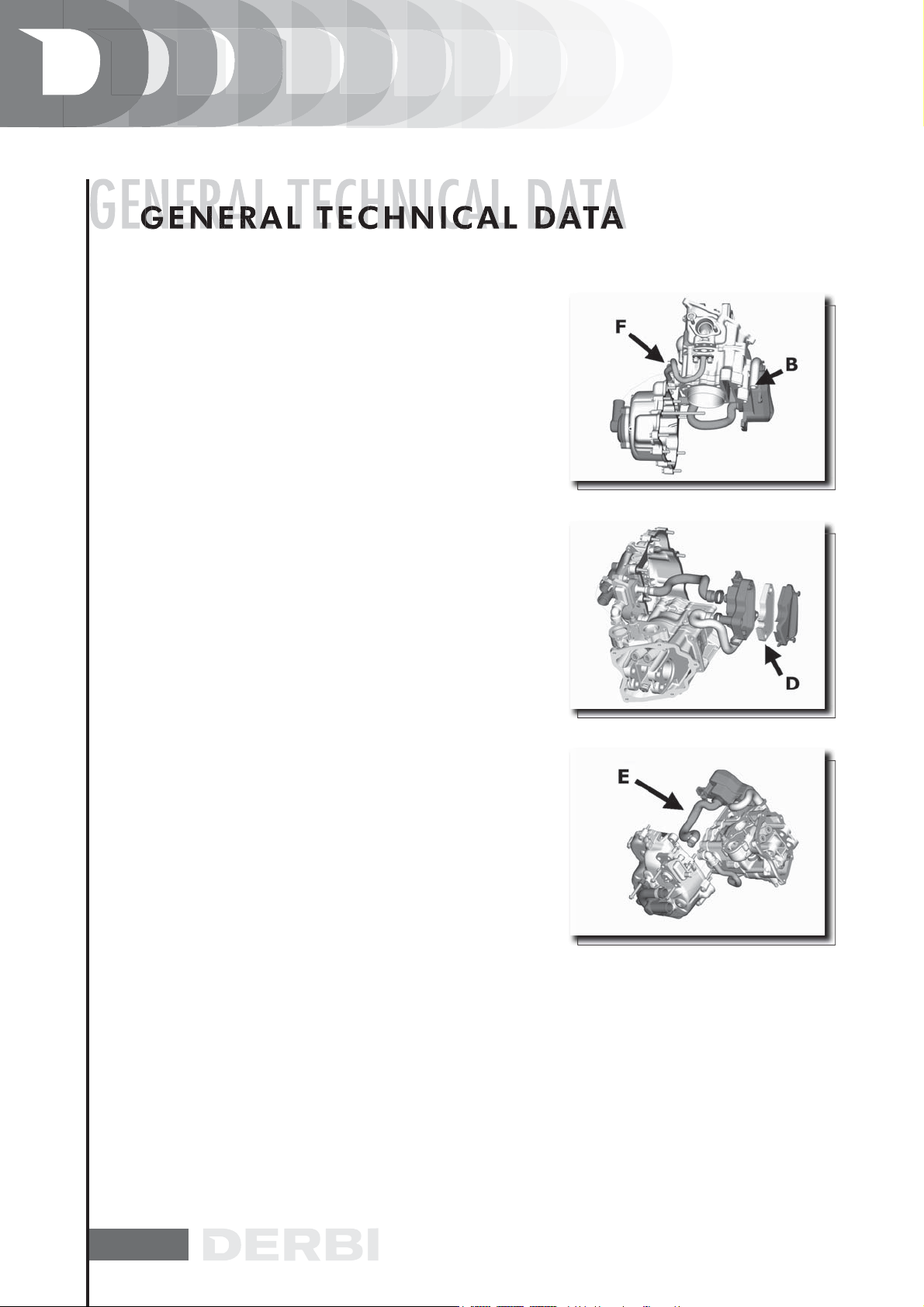
The working principie ofthe SAS for Quasar 250 cc Euro 2
engines is entirely similar to the SAS employed on 2-stroke
engines. The main differences are the following:
Secondary air enters directly into the exhaust duct on the
cylinder head, instead of entering through the exhaust pipe
as in two-stroke engines.
The reed valve found on 2-stroke engines is here replaced
by a membrane.
Unit «A», shown in the figure, is provided with a cut-off connected to the vacuum inlet on the intake manifold to shut air
inlet during deceleration, so to prevent detonations in the
silencer. Air is sucked in through hole «B» and flows inside
the duct into air-box «C» where it is filtered by filtering element «D».
The filtered air now enters membrane device «A», through
duct «E» and is then guided towards the head.
Flowing through pipe «F», flanged to the head, secondary
air reaches the exhaust duct thus providing oxygen addition
to the unburnt gases just before they enter the catalytic con
verter.
The efficiency of the catalyzing process is therefore increased.
14
Page 16
CARBURATTOR HEIHIN
Version 125
SPECIFICATION
Depresione type
Printing on the body
Device CUT-OFF
Max. jet
Minimum jet
Max. air jet
Minimum air jet
Idle mixture adjusment screw initial opening
Conical pin
Emulsifier nozzle
Starter air jet
Starter jet
Starter device resistance
Venturi choke
Throttle valve
Choke maximum cone
CARBURETTOR WALBRO
DESC. / QUANTITY
CVEK30
CVK
Not present
105
35
70
130
2 ±1/4
Ø 2,450
Ø 2,8
Ø 1,5
42
~20
Ø 29
Ø 30,5
Ø 47
SPECIFICATION
Type to depression
Printing on the body
Device CUT-OFF
Max jet
Minimum jet
Max air jet.
Minimum air jet
Gas valve spring
Idle mixture adjustment screw initial opening
Conical pin printing
Conical pin notches position from top
Emulsifier nozzle
Choke máximum cone
Starter air jet
Starter emulsifier jet
15
DESC. / QUANTITY
WVF-7G*
7G
Not present
108
36
115
100
100 gr
2 5/8 ± 1/2
51C
2
Ø 2,7
Ø 1,5
200
130
Page 17
CARBURADOR WALBRO
SPECIFICATION
Starter jet
Starter pin diameter
Starter device resistance
Choke
Throttie valve
Choke máximum cone
CARBURATTOR HEIHIN
Version 250
SPECIFICATION
Depression type
Printing on the body
CUT-OFF device
Max jet
Minimum jet
Max air jet
Mínimum air jet
Idle mixture adjustment screw initial opening
Conical pin
Emulsifier nozzle
Starter air jet
Starter jet
Starter device resistance
Venturi choke
Throttie valve
Choke máximum cone
DESC. / QUANTITY
50
Ø 1,78
~ 40Q
Ø 29 (30,3x27,0)
Ø 33
Ø 48,0
DESC. / QUANTITY
CVEK30
CVK
Present
100
38
70
115
2½ ± ¼
Ø 2,530
Ø 2,8
Ø 1,5
42
~ 20
Ø 29
Ø 30,5
Ø 47
16
Page 18
CARBURATTOR WALBRO
Version 250
SPECIFICATION
Depression type
Printing on the body
CUT-OFF device
Max jet
Minimum jet
Max air jet
Mínimum air jet
Gas valve spring
Idle mixture adjustment screw initial opening
Conical pin
Tacche dall’alto spillo cónico
Emulsitier nozzle
Choke máximum cone
Starter air jet
Starter emulsifier jet
Starter jet
Starter pin diameter
Starter device resistance
Choke
Throttie valve
Choke máximum cone
* The identification letter can vary every time the carburettor is updated.
WVF-7S*
7S
Presente
118
34
150
31
120 gr
3±½
465
3
Ø 2,7
Ø 1,5
200
130
50
Ø 1,78
~ 40
Ø 29 (30,3x27,0)
Ø 33
Ø 48,0
DESC. / QUANTITY
17
Page 19

CHASSIS TIGHTENING TORQUES
DESCRIPTION
M8X125 8.8 FRONT FRAME-CHASSIS SECUR.DEVICE
M8X125 8.8 SUBCHASSIS-CHASSIS SEC.DEVICE
M10x150 12.9 TOP SHOCK ABSOR.-CHASSIS SEC.DEVICE
M10x150 12.9 BOTTOM SHOCK ABSOR.-ENG. SEC.DEV.
M14x200 8.8 FRONT ENG. SUPPORT-CHASSIS SEC.DEV.
M10X150 8.8 REAR ENG.SUPP-FRONT ENG.SUPP. SEC.DEV.
M10X150 8.8 ENGINE-REAR SUPP. SEC.DEV.
M8X125 8.8 ENGINE SUPP. SILENTBLOC CLAMP SEC.DEV.
M8X125 8.8 SHOCK ABSORBER SUPP. SEC.DEV.
M8X125 12.9 SHOCK ABSOR. SUPP. TO CRANKCASE SEC.DEV.
M12X175 12.9 SHOCK ABSORBER SUPP. TO SUSP. ARM SEC.DEV. M12X175 12.9
M30,5X150 FORKS FLANGE SEC.DEV.
M6x100 HORN-CHASSIS SEC.DEV.
M10X150 8.8 STAND SEC.DEV.
M8Z125 8.8 FOOTREST SUPPORT-CHASSIS SEC.DEV.
M7x100 8.8 EXHAUST PIPE-CYLINDER SEC.DEV.
M8X125 8.8 SILENCER-SUSPENSION ARM SEC.DEV.
M6x100 8.8 STEERING LOCK-CHASSIS SEC.DEV.
M8x125 8.8 HANNDLEBARS-STEERING FORKS SEC. DEV.
M8x125 8.8 HANDLEBAR CLAMP SEC.DEV.
M5x80 8.8 COUNTERWEIGHT-HANDLEBAR SEC.DEV.
M14x150 FRONT WHEEL-FORKS SEC.DEV.
M8x125 FORK ARM LOCK SEC.DEV.
M6x100 10.9 BRAKE DISK-FRONT WHEEL SEC.DEV.
M10x150 8.8 FR. BRAKE CALLIPER-FORKS SEC.DEV.
M8X125 12.9 SUSP. ARM-ENGINE SEC. DEV.
M16X125 10.9 REAR HUB-ENGINE SEC.DEV.
M8X40 10.9 REAR WHEEL-HUB SEC.DEV.
M8X125 8.8 REAR CALLIPER SUPP.-CRANKCASE SEC.DEV.
M8X125 8.8 REAR CALLIPER-CALLIPER SUPP. SEC.DEV.
M6x100 10.9 BRAKE DISK-REAR HUB SEC. DEV.
M8x125 8.8 CLAMP-CHASSIS SEC.DEV.
M6x100 RADIATOR-CHASSIS SEC.DEV.
THERMOSTAT SWITCH-RADIADOR SEC.DEV.
M5X80 8.8 ELECT.FAN-CHASSIS SEC.DEV.
M5x80 VARIOUS METAL PARTS TO CHASSIS SEC.DEV
M6x100 VARIOUS METAL PARTS TO CHASSIS SEC.DEV.
M8x125 VARIOUS METAL PARTS TO CHASSIS SEC.DEV.
M5x80 VARIOUS PLASTIC PARTS TO CHASSIS SEC.DEV.
M6x100 VARIOUS PLASTIC PARTS TO CHASSIS SEC.DEV.
(•) Sellador the thread type locktite 243
TORQUES
(N.M)
1,7÷1,9
1,7÷1,9
4,5÷5,5
4,5÷5,5
7÷8
3÷4
3÷4
1,7÷1,9
1,7÷1,9
3÷3,5
6÷6,5
9÷13
0,8÷1
3÷4
1,7÷1,9
1÷1,3
1,7÷1,9
0,8÷1
1,7÷1,9
1,7÷1,9
0,35÷0,45
7÷8
1,5÷1,9
1÷1,2
3,5÷4
2,2÷2,5
11, 5÷12,5
2,7÷2,9
1,7÷1,9
1,7÷1,9
1÷1,2
1,7÷-1,9
0,8÷1
1,7÷2,2
0,4÷0,5
0,35÷0,45
0,8÷1
1,5÷1,9
0,1÷0,2
0,2÷0,35
TORQUES
(M.KG)
17÷19
17÷19
45÷55
45÷55
70÷80
30÷40
30÷40
17÷-19
17÷19
30÷35
60÷65
90÷130
8 ÷ 10
30÷40
17÷19
10÷13
17÷19
8÷10
17÷19
17÷19
3,5÷4,5
70÷80
15÷19
10÷12
35÷40
22÷25
115 ÷12 5
27÷29
17÷19
17÷19
10÷12
17÷19
8÷10
17÷22
4÷5
3,5÷4,5
8÷10
15÷19
1÷2
2÷3,5
SEALER
.
.
.
.
.
.
.
18
Page 20

EXAUST PIPE
NAME
Screw clamping manifold to silencer
Screw clamping heat shield to silencer
Exhaust gas intake screw
Screw fixing silencer support arm to crankcase
Exhaust pipe/support bracket fixing screw.
Exhaust pipe/cylinder head fixing nut.
ENGINE - LUBRICATION
NAME
Hub oilexhaust cap
Oil filter unión on crankcase
Engine oil / net filter drainage cap
Oil filter
Oil pump cover screws
Screws fixing the oil pump to the crankcase
Oil pump control rim screw
Oil pump cover píate screws
Oil sump screws
Minimum oil pressure sensor
TORQUE IN Nm
15,5 ÷ 18,5
5 ÷ 6
22 ÷ 26
33 ÷ 41
27 ÷ 30
16 ÷ 18
TORQUE IN Nm
15 ÷ 17
27 ÷ 33
24 ÷ 30
4 ÷ 6
0,7 ÷ 0,9
5 ÷ 6
10 ÷ 14
4 ÷ 6
10 ÷ 14
12 ÷ 14
CYLINDER HEAD
NAME
Spark plug
Cylinder head cover screw (1) (A)
Head fastening side screws
Start up mass screws
M5 side screw fastening washers on cam
shaft (125 cc)
19
TORQUE IN Nm
12 ÷ 14
9 ÷ 11 + 180°
11 ÷ 13
7 ÷ 8,5
7 ÷ 8,5
Page 21
CYLINDER HEAD
NAME
Tappet adjustment lock nut
Timing chain tightener sliding block screws
Start up mass bell screws
M6 central screw fastening washers on
cam shaft (125 cc)
Timing beit tightener support screw
Timing beit tightener central screw
Camshaft retain píate screw
TRANSMISSION
NAME
Beit support roller screw
Clutch assembly nut on driven pulley
Driving pulley screw
Transmission cover screw
Driven pulley axis
Hub cover screws
TORQUE IN Nm
6 ÷ 8
10 ÷ 14
11 ÷ 15
11 ÷ 15
11 ÷ 13
5 ÷ 6
4 ÷ 6
TORQUE IN Nm
11 ÷ 13
45 ÷ 50
75 ÷ 83
11 ÷ 13 Nm
54 ÷ 60
24 ÷ 27
FLYWHEEL
NAME
FIywheel cover fastening
Stator cover screws (°)
FIywheel nut (125)
FIywheel nut (250)
Pick-Up fixing screws
Free wheel fixing screws on the flywheel
20
TORQUE IN Nm
5 ÷ 6
3 ÷ 4
52 ÷ 58
94 ÷ 102
3 ÷ 4
13 ÷ 15
Page 22

ENGINE CRANKCASE AND SHAFT
NAME
Engine crankcase inside head screws
(transmission side half shaft)
Engine crankcase coupling screws
Starter motor screws
Crankcase timing cover screws
4 ÷ 6
11 ÷ 13
11 ÷ 13
3,5 ÷ 4,5
TORQUE IN Nm
COOLING
NAME
Water pump impeller cover
Water pump impeller drive joint screw
Thermostat cover screws
(°) Apply threadlocking LOCTITE médium, type 242.
(*) Tighten the two screws after tightening the rear wheel spindie nut with the prescribed torque.
(A)Tighten the nuts ¡n two phases, following a crosswise pattern.
3 ÷ 4
3 ÷ 4
3 ÷ 4
TORQUE IN Nm
(1) Lubrícate nuts with engine oil before fitting.
21
Page 23

OVERHAUL DATA
ASSEMBLY CLEARANCES
CYLINDER - PISTON ASSY
CATEGORIES COUPLING 125
NAME
Cylinder
Cylinder
Piston
Piston
Cylinder first uprat.
Cylinder first uprat.
Piston first uprat.
Piston first uprat.
Cylinder second uprat.
Cylinder second uprat.
Piston second uprat.
Piston second uprat.
Cylinder third uprat.
Cylinder third uprat.
Piston third uprat.
Piston third uprat.
PLAY
57+0,025±0,003
57+0,025±0,003
56,959±0,014
56,959±0,014
57,2+0,025±0,003
57,2+0,025±0,003
57,159±0,014
57,159±0,014
57,4+0,025±0,003
57,4+0,025±0,003
57,359±0,014
57,359±0,014
57,6+0,025±0,003
57,6+0,025±0,003
57,559±0,014
57,559±0,014
INITIALS
A
B
C
D
A1
B1
C1
D1
A2
B2
C2
D2
A2
B3
3C
D3
CYLINDER
56,997 ÷ 57,004
57,004 ÷ 57,011
57,011 ÷ 57,018
57,018 ÷ 57,025
57,197 ÷ 57,204
57,204 ÷ 57,211
57,211 ÷ 57,218
57,218 ÷ 57,225
57,397 ÷ 57,404
57,404 ÷ 57,411
57,411 ÷ 57,418
57,418 ÷ 57,425
57,597 ÷ 57,604
57,604 ÷ 57,611
57,611 ÷ 57,618
57,618 ÷ 57,625
PISTON
56,945 ÷ 56,952
56,952 ÷ 56,959
56,959 ÷ 56,966
56,966 ÷ 56,973
57,145 ÷ 57,152
57,152 ÷ 57,159
57,159 ÷ 57,166
57,166 ÷ 57,173
57,345 ÷ 57,352
57,352 ÷ 57,359
57,411 ÷ 57,418
57,366 ÷ 57,373
57,545 ÷ 57,552
57,552 ÷ 57,559
57,559 ÷ 57,566
57,566 ÷ 57,573
PLAY ON
FITTING
0,045-0,059
0,045-0,059
0,045-0,059
0,045-0,059
0,045-0,059
0,045-0,059
0,045-0,059
0,045-0,059
0,045-0,059
0,045-0,059
0,045-0,059
0,045-0,059
0,045-0,059
0,045-0,059
0,045-0,059
0,045-0,059
22
Page 24

on
n
r
ylinder
COUPLING CATEGORIES ENGINE 250
NAME
Cylinder
C
Cylinde
Cylinder
Pisto
Piston
Pist
Piston
PISTON RINGS
PLAY
72+0,018±0,010
72+0,018±0,010
71,967±0,014
71,967±0,014
INITIAL
A
B
C
D
CYLINDER
71,990 ÷ 71,997
71,997 ÷ 72,004
72,004 ÷ 72,011
72,011 ÷ 72,018
PISTON
71,953 ÷ 71,960
71,960 ÷ 71,967
71,967 ÷ 71,974
71,974 ÷ 71,981
PLAY ON FITTING
0,030-0,044
0,030-0,044
0,030-0,044
0,030-0,044
UPRATING TABLE ENGINE 125
NAME
Compression lining
Scraper ring lining
Scraper ring lining
DESCRIPTION DIMENSIONS
57 x 1
57 x 1
57 x 2,5
INITIALS
A
A
A
QUANTITY
0,15 ÷ 0,30
0,10 ÷ 0,30
0,15 ÷ 0,35
23
Page 25

OVERSIZES ENGINE 250
NAME
Compression lining
Scraper ring lining
Scraper ring lining
DESCRIPTION DIMENSIONS
72 x 1,5
72 x 1
72 x 2,5
CRANKCASE - CRANKSHAFT - CONNECTING ROD
CRANKCASE - DRVING SHAFT - BENCH HALF BEARING
NAME
Half crankshaft bearing
Half crankshaft bearing
Half crankshaft bearing
Crankshaft cat. 1 - Crankcase cat. 1
Crankshaft cat. 1 - Crankcase cat. 2
Crankshaft cat. 2 - Crankcase cat. 1
Crankshaft cat. 2 - Crankcase cat. 2
Crankshaft
Crankshaft
Carter
Carter
DESCRIPTION DIMENSIONS INITIALS
INITIALS
A
A
A
Type A -red
Type B - blue
Type C - yellow
Category 1
Category 2
Category 1
Category 2
QUANTITY
0,15 ÷ 0,30
0,20 ÷ 0,40
0,20 ÷ 0,40
QUANTITY
1,970 ÷ 1,973
1,973 ÷ 1,976
1,976 ÷ 1,979
C - C
B -B
B - B
A -A
28,998 ÷ 29,004
29,004 ÷ 29,010
32,959 ÷ 32,965
32,953 ÷ 32,959
24
Page 26

FITTING CLEARANCE
Driving shaft/case axial clearance: Standard clearance 0,15 ÷ 0,40mm (cold engine).
CARNCSHAFT - CRANKCASE AXIAL CLEARANCE/CARTER
NAME
Half shaft transmission side
Half shaft flywheel side
Conecting rod
Spacing tool
DESCRIPTION DIMENSIONS INITIALS
16,6+0- 0,05
16,6+0- 0,05
18- 0,10-0,15
51,4+0,05
A
B
C
D
QUANTITY
D = 0,20 ÷ 0,50
D = 0,20 ÷ 0,50
D = 0,20 ÷ 0,50
D = 0,20 ÷ 0,50
25
Page 27

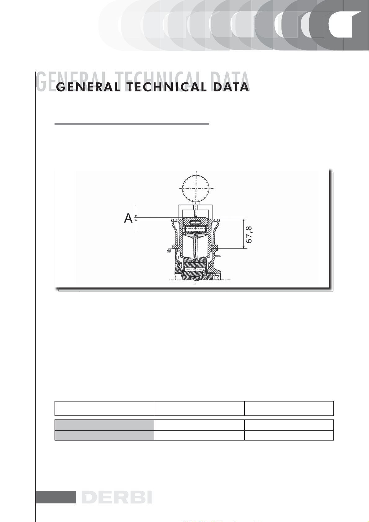
SLOT PACKING SYSTEM
Characteristics
Compresion ratio - 125cc verion
Rc: 11,50÷13:1
The length «A» to be measured refers to the pistón protrusion. It indicates the amount by which the surface formed
by the pistón crown tops the surface formed by the upper parí of the cylinder. The more the pistón descends into the
cylinder, the less the base gasket to be applied (to recover the compression ratio) will be and vice versa.
N.B.
THE MEASUREMENT OF «A» MUST BE CARRIED WITH THE PISTÓN AT THE TDC, WITHOUT ANY GASKET
INSTALLED BETWEEN THE CRANKCASE AND THE CYLINDER, AND AFTER RESETTING THE COMPARATOR,
COMPLETE WITH SUPPORT, ON A RECTIFIED SURFACE.
125CC VERSIÓN WITH FIBRE HEAD GASKET (1.1)
NAME
Thicknesses 125
Thicknesses 125
MEASURE A THICKNESS
2,20÷2,45
2,45÷2,70
0,4 ± 0,05
0,6 ± 0,05
26
Page 28
SLOT PACKING SYSTEM
Characteristics
Compresion ratio - 125cc verion
Re: 11,50÷13:1
The length «A» to be measured refers to the pistón protrusion. It indicates the amount by which the surface formed
by the pistón crown tops the surface formed by the upper part of the cylinder. The more the pistón descends into the
cylinder, the less the base gasket to be applied (to recover the compression ratio) will be and vice versa.
N.B.
THE MEASUREMENT OF «A» MUST BE CARRIED WITH THE PISTÓN AT THE TDC, WITHOUT ANY GASKET
INSTALLED BETWEEN THE CRANKCASE AND THE CYLINDER, AND AFTER RESETTING THE COMPARATOR,
COMPLETE WITH SUPPORT, ON A RECTIFIED SURFACE.
125CC VERSIÓN WITH METALLIC HEAD GASKET (0.3)
NAME
Thicknesses 125
Thicknesses 125
MEASURE A THICKNESS
1,40÷1,65
1,65 ÷1,90
0,4 ± 0,05
0,6 ± 0,05
27
Page 29

SISTEMA DE MONTAJE DE ESPESORES
Características Técnicas
Relación de compresión versión 250
Re: 10,5-11,5
MEASUREMENT (A)
(WITH PISTON AT T.D.C.)
NOTE
MEASUREMENT (A) MUST BE TAKEN WITHOUT TRIM MOUNTED BETWEEN THE
CASING AND THE CYLINDER, AFTER HAVING PUT THE COMPARATOR TO ZERO,
WITH ITS SUPPORT, ON A FLAT PLANE.
NOTE
MOUNT ACCORDING TO THE
MEASUREMENT (A) OBTAINED
N.B.
THE MEASURE «A» TO TAKE IS A PISTÓN PROTRUSION VALUÉ THAT INDICATES HOW MUCH THE PLAÑE
FORMED BY THE PISTÓN TOP PROTRUDES FROM THE PLAÑE FORMED BY THE TOP OF THE CYLINDER.
THE MORE THE PISTÓN PROTRUDES FROM THE CYLINDER, THE MORE THE BASE GASKET TO APPLY (TO
RECOVER THE COMPRESSION RATIO) AND VICE VERSA.
SHIMMING 250
NAME
Shimming 250
Shimming 250
Shimming 250
MEASURE A THICKNESS
2,60÷2,50
2,50÷2,30
2,30÷2,20
0,4 ±0,05
0,6 ± 0,05
0,8 ± 0,05
28
Page 30

OVERSIZES
OVERSIZES ENGINE
NAME
Compression lining 1° greater
First uprated scraper ring lining
First uprated scraper ring lining
Second uprated compression lining
Second uprated scraper ring lining
Second uprated scraper ring lining
Third uprated compression lining
Third uprated scraper ring lining
Third uprated scraper ring lining
DESCRIPTION DIMENSION
57,2 x 1
57,2 x 1
57,2x 2,5
57,4 x 1
57,4 x 1
57,4 x 2,5
57,6 x 1
57,6 x 1
57,6 x 2,5
RECOMENDEDS PRODUCTS
DESCRIPTION SPECIFICATIONS
Rear hub oil
Air filter sponge oil
Complex calcium soap grease NLGI 1-2
Engine oil
Brake fluid
Cooling fluid
Grease for driven pulley shaft compensating ring and
mobile driven pulley sliding seat
Grease for steering wheel bearings and pin seats
Oil for four stroke engines
Oil SAE 80W/90 of higher quality than API GL3 Specifications
Mineral oil with specific additives to increase adhesión ISO
VG
Grease (brake command levers, Gas)
Synthetic oil SAE 5W/40 of higher quality than API SJ Specifications
Synthetic fluid SAE J1703, NHTSA 116 DOT 4, ISO 4925
Mono-ethyiene glycol based anti-freeze, CUNA NC 956-16 fluid
Molybdenum bisulphide grease
Lithium soap and zinc oxide grease NLGI2 for the oscillating arm
Oil for flexible transmission lubrication (gas control)
INITIALS
A
A
A
A
A
A
A
A
A
QUANTITY
0,15 ÷ 0,30
0,10 ÷ 0,30
0,15 ÷ 0,35
0,15 ÷ 0,30
0,10 ÷ 0,30
0,15 ÷ 0,35
0,15 ÷ 0,30
0,10 ÷ 0,30
0,15 ÷ 0,35
29
Page 31

PPREPARATION FOR REMOVAL AND DISMANTLING
1. Remove all the dirt, grime, dust and other foreign material
before removing and dismantling.
2. Use properly cleaned tools and equipment.
See “SPECIAL TOOLS”.
3. On dismantling the motorcycle, always keep paired parts
together. This includes gears, cylinders, pistons and other
parts submitted to natural wear in pairs. Paired parts must
always be reassembled or replaced together.
4. While dismantling the motorcycle, clean all the parts and
lay them out on trays in the order dismantled. This speeds up
reassembly and ensures the correct fitting of all the parts.
5. Keep all parts away from any contact with fire.
30
Page 32

REPLACEMENT PARTS
C S
TAB/SPACER WASHERS AND SPLIT PINS
1. Use only genuine DERBI spare parts. For all lubrication
tasks use oils and greases recommended by DERBI. Other
makes make seem similar in their function and appearance,
but are inferior in quality.
SEALS, RETAINING RINGS AND O-RINGS
1. Replace all seals, retaining rings and O-rings when servi-
cing the engine.
All surfaces receiving seals, retaining ring edges and O-rings
must be cleaned.
2. Apply oil to all paired parts and bearing during reassembly. Apply grease to the retaining ring edges.
TAB/SPACER WASHERS AND SPLIT PINS
1. After removing them, replace all tab/spacer washers (1)
and split pins Bend the tabs to fit the flat surfaces of the
bolt or nut once they have been tightened to the specified
torque.
BEARINGS AND RETAINING RINGS
1. Fit bearings and retaining rings in such a way that the ma-
nufacturers marks remain visible. On fitting retaining rings,
applying a thin film of light lithium soap based grease to
their edges. Where required, apply oil generously when fitting bearings.
WARNING
DO NOT USE COMPRESSED AIR TO DRY BEARINGS. THIS
DAMAGES THE BEARING SURFACES.
31
Page 33

LOCKING RINGS
OC G GS
1. Examine all the locking rings carefully before fitting.
Always replace the gudgeon pin circlips after every use. Replace distorted locking rings. On fitting a locking ring (1),
ensure that the sharp edge (2) is on the opposite side to the
force to be applied to it.
See the figure on the side, (4) Axle.
SPECIAL TOOLS
1. The following special tools are needed for assembly and
for complete and exact adjustments. Only use the proper
special tools; thereby avoiding damage caused by the use of
unsuitable tools or improvised techniques.
020151Y
020331Y
020333Y
020334Y
STORES CODE
IMAGEDESCRIPTION
Air heater
Digital multimeter
Single battery charger
Multiple battery charger
001467Y014
32
15 mm plier s
Page 34

STORES CODE
DESCRIPTION
IMAGE
020412Y
020335Y
020565Y
020439Y
020359Y
15mm guide
Magentic stand and
comparator
Compass flywheel stop
spanner
17mm guide
42 x 47mm hub bearing fitting
adaptor
020363Y
002095Y
008564Y
020434Y
33
20mm guide
Engine support
Flywheel extractor
Oil presure gauge connection
Page 35

STORES CODE
IMAGEDESCRIPTION
020382Y011
020424Y
020431Y
020193Y
020306Y
Bushing (valve remover)
Driven pulley roller casing drift
Valve oil seal extractor
Oil pressure gauge
Valve sealing ring drift
020360Y
020364Y
020375Y
34
52 x 55mm adaptor
25mm guide
Adapter 28 x 30mm
Page 36

STORES CODE
IMAGEDESCRIPTION
020376Y
020444Y
020330Y
001467Y035
020368Y
Handle for punches
Driven half pulley spring compressor tool
Stroboscopic gun fot two-and
four-stroke engines
Bell
Driving pulley stop wrench
020319Y
020287Y
020263Y
35
Immobilizer control test
Piston band clamps (engine
125 c.c)
Protective sheath
Page 37

STORES CODE
IMAGEDESCRIPTION
020262Y
020430Y
020428Y
020426Y
020425Y
Crankcase detachment plate
Pin retainers installation tool
(engine 125cc)
Piston position check support
Piston fitting fork
Flywheel-side oil guard punch
36
020423Y
020414Y
020393Y
Driven pulley stop key
28 mm guide - Hub bearing
asembly
Piston band clamps
(Engine 200-250cc)
Page 38

STORES CODE
IMAGEDESCRIPTION
020382Y
020455Y
020442Y
020440Y
020329Y
Tool for removing valve cotters
equipped with part 012
10mm guide
Pulley stop wrench
Water pump overhaul tool
Pump
020357Y
020409Y
020456Y
37
32 x 35 mm adaptor
Multimeter adpater (Peak voltage measurement)
Ø 24mm adaptor
Page 39

STORES CODE
IMAGEDESCRIPTION
020332Y
020074Y
002465Y
020454Y
020622Y
Digital rpm counter
Crankshaft aligning tool
Pliers dor snap rings
Pin retainers installation tool
Transmission-side oil guard
punch
020444Y011
020444Y009
001467Y
38
Adapter ring
45 x 55 wrench
Bell
Page 40

STORES CODE
IMAGEDESCRIPTION
001467Y013
020444Y008
020244Y
020115Y
020271Y
15mm pliers
Adapter ring
Drift Ø 15
Drift Ø 18
Slient-block installation / removal tool
020627Y
020467Y
020626Y
39
Flywheel stop key
Flywheel estractor
Driving pulley stop key
Page 41

MAINTENANCE CHART
C C
S
3000
VERY
EVERY 3000 KM
ACTION
Engine Oil Level Check/Top up
EVERY 2 YEAR
EVERY 2 YEARS
ACTION
Cooling Fluid Replacement
Brake fluid Change
Secondary air filter (external - internal) - Cleaning (125)
AT 1.000 KM OR 4 MONTHS
ACTION
Engine oil Replacement
Hub Oil Replacement
Oil filter Replacement
Idling speed Adjustment
Acceleration command Adjustment
Steering Adjust
Brake levers Grease
Brake pads Check condition + wear
Brake fluid level Check
Nuts, bolts and fasteners Check
Electrical system and battery Check
Tires-inflation and wear Check
Vehicle and brake test Road test
KM
AT 6.000 KM OR 12 MONTHS
ACTION
Engine oil Replacement (125)
Hub oil level Check
Spark Plug/Electrodes distance Check
Air Filter Cleaning
Oil filter Replacement (125)
125 cc Valve Play Check
Roller support sliding blocks / Varistor rollers Check
40
Page 42

AT 6.000 KM OR 12 MONTHS
ACTION
Transmission Belt Check
Cooling fluid level Check
Brake pads Check condition + wear
Brake fluid level Check
Electrical system and battery Check
Tires-inflation and wear Check
Vehicle and brake test Road test
AT 12.000 KM OR 24 MONTHS AND 60.000 KM
ACTION
Engine oil Replacement
Hub oil level Check
Spark plug/Electrode gap Check/Change
Air Filter Cleaning
Oil filter Replacement
Idling speed S& Adjustment
Roller support sliding blocks / Varistor rollers Change
Acceleration command Adjustment
Cooling fluid level Check
Steering Adjust
Brake levers Grease
Brake pads Check condition + wear
Brake fluid level Check
Transmissions Lubricate
Nuts, bolts and fasteners Check
Suspensions Check
Electrical system and battery Check
Headlight Adjust
Tires-inflation and wear Check
Vehicle and brake test Road test
Transmission Belt (125 cc) Replacement
Transmission Belt Check (250)
41
Page 43

AT 18.000 KM AND 54.000 KM
ACTION
Engine oil Replacement (125)
Hub oil level Check
Spark Plug/Electrodes distance Check
Air Filter Cleaning
Oil filter Replacement (125)
125 cc Valve Play Check
250 cc Valve Play Check
Roller support sliding blocks / Varistor rollers Check
Cooling fluid level Check
Radiator External cleaning/Check
Brake pads Check condition + wear
Brake fluid level Check
Electrical system and battery Check
Tires-inflation and wear Check
Vehicle and brake test Road test
Secondary air filter (250) Cleaning
Transmission Belt Replacement (250)
Transmission Belt (125 cc) Replacement
AT 24.000 KM AND 48.000 KM
ACTION
Engine oil Replacement
Hub Oil Replacement
Spark plug/Electrode gap Check/Change
Air Filter Cleaning
Oil filter Replacement
Idling speed Adjustment
Roller support sliding blocks / Varistor rollers Change
Acceleration command Adjustment
Cooling fluid level Check
Steering Adjust
Brake levers Grease
Brake pads Check condition + wear
Brake fluid level Check
Transmissions Lubricate
Nuts, bolts and fasteners Check
Suspensions Check
42
Page 44

AT 24.000 KM AND 48.000 KM
ACTION
Electrical system and battery Check
Headlight Adjust
Tires-inflation and wear Check
‘ Vehicle and brake test Road test
Transmission Belt Check (250)
AT 30.000 KM. 42.000 KM AND 66.000 KM
ACTION
Hub oil level Check
Spark Plug/Electrodes distance Check
Air Filter Cleaning
Varistor rollers Check or Replacement
Transmission Belt Check
Cooling fluid level Check
Brake pads Check condition + wear
Brake fluid level Check
Electrical system and battery Check
Tires-inflation and wear Check
Vehicle and brake test Road test
Engine oil Replacement (125)
Oil filter Replacement (125)
AT 36.000 KM
ACTION
Engine oil Replacement
Hub oil level Check
Spark plug/Electrode gap Check/Change
Air Filter Cleaning
Oil filter Replacement
125 cc Valve Play Check
250 cc Valve Play Check
Idling speed Adjustment
Roller support sliding blocks / Varistor rollers Change
Acceleration command Adjustment
Transmission Belt Replacemen
43
Page 45

AT 36.000 KM
ACTION
Cooling fluid level Check
Radiator External cleaning/Check
Steering Adjust
Brake levers Grease
Brake pads Check condition + wear
Flexible brake lines Change
Brake fluid level Check
Transmissions Lubricate
Nuts, bolts and fasteners Check
Suspensions Check
Electrical system and battery Check
Headlight Adjust
Tires-inflation and wear Check
Secondary air filter (250) Cleaning
Vehicle and brake test Road test
AT 72.000 KM
ACTION
Engine oil Replacement
Hub Oil Replacement
Spark plug/Electrode gap Check / Change
Air Filter Cleaning
Oil filter Replacement
125 cc Valve Play Check
250 cc Valve Play Check
Idling speed Adjustment
Roller support sliding blocks /Varistor rollers Change
Acceleration command Adjustment
Transmission Belt Replacemen
Cooling fluid level Check
Radiator External cleaning/Check
Steering Adjust
Brake levers Grease
Brake pads Check condition + wear
Flexible brake lines Change
Brake fluid level Check
44
Page 46

AT 72.000 KM
ACTION
Transmissions Lubricate
Nuts, bolts and fasteners Check
Suspensions Check
Electrical system and battery Check
Headlight Adjust
Tires-inflation and wear Check
Secondary air filter (250) Cleaning
Vehicle and brake test Road test
45
Page 47

ENGINE OIL
ENGINE OIL 125 C.C.
ENGINE OIL 250 C.C.
HUB OIL LEVER
DRIVE BELT 125 C.C.
DRIVE BELT 250 C.C.
TRANSMISSION
OIL FILTER 125 C.C.
OIL FILTER 250 C.C.
AIR FILTER
SECONDARY OIL FILTER 125 C.C.
SECONDARY OIL FILTER 250 C.C.
SPARK PLUG / ELECTRODE GAP
ELECTRICAL SYSTEM AND BATTERY
VALVE CLEARANCE
WHEEL BEARINGS
IDLE SPEED / FUEL – AIR MIXTURE
THROTTLE CONTROL
STEERING
BRAKE LEVERS
BRAKE PADS/SHOES
BRAKE FLUID
LEVEL BRAKE FLUID
FLEXIBLE BRAKE FLUID PIPELINES
TYRE PRESSURE AND CONDITION
SUSPENSION
HEADLIGHT
COOLING LIQUID
RADIATOR
NUTS, BOLTS AND AND FASTENINGS
VEHICLE AND BRAKE TEST
1000 km - 2 Months
6000 km - 12 Monthse
12000 km - 24 Monthse
18000 km - 36 Monthse
24000 km
30000 km
36000 km
42000 km
48000 km
Check level / top up every 3000 km
Check every 2 years
Replace every 2 years
Replace every 2 years
54000 km
60000 km
66000 km
72000 km
REMPLACE CHECK CLEAN LUBRICATION ADJUSTMENT
46
Page 48

CARBURETTOR
- Disassemble all carburettor components, accurately wash
them in solvent, then dry them with compressed air. To ensure thorough cleaning, pay special attention to the passages
in the carburettor body.
- Carefully check the condition of all components.
- The throttle must slide freely in the chamber, if the play is
excessive because or wear-replace the throttle.
- Replace the carburettor if the chamber shows signs of wear
as to prejudice the valve’s regular seal or free sliding (though
it is new).
- When reassembling the carburettor, it is a good rule to
replace the gaskets.
WARNING
PETROL IS HIGHLY EXPLOSIVE. ALWAYS FIT NEW SEALS
AND GASKETS TO PREVENT LEAKAGE.
Diaphragm cover
Throttle valve spring
Conical needle support
Conical needle spring
Conical needle
Throttle valve diaphragm
Automatic starting device
Idle speed adjusting screw
Accelerating pump rocker
Idle mixture adjusting screw
Float pin
Accelerating pump assembly
Float
Float chamber
Idling Jet
Main jet
Diffuser
Float chamber drain screw
01
02
03
04
05
06
07
08
09
10
11
12
13
14
15
16
17
18
47
Page 49

CHECKING THE SPARK ADVANCE
- To check the ignition advance, use the stroboscopic lamp
with induction collet connected to the spark plug power supply cable.
- Connect the induction collet according to the right polarity
(the arrow on the collet must be facing the spark plug).’
- Set the lamp selector to the central position (1 spark = 1
driving shaft revolution as in 2 stroke engines).
- Start the engine and check that the lamp is in good working
order and that the rpm counter reads high speeds too (e.g.
8,000 rpm).
- If you detect abnormal flashes or rpm reads, increase the
resistive load on the spark plug supply line (10 - 15 KQ in
series with the H.V. cable).
Version 125
- Remove the slit plastic cap on the flywheel cover.
- Adjust the lamp flash dephasing corrector to make the reference on the flywheel cover collimate with the level on the
water pump drive. Read the advance degrees indicated by
the stroboscopic lamp.
Characteristic
Ignition advance (before T.D.C) 125
10° ± 1° at 2000 r.p.m. - 34° ± 1° at 6000 r.p.m
Version 250
- Remove the spark plug.
- Remove the plastic cover from the slotted hole on the
flywheel cover, indicated in the picture.
48
Page 50

- Remove the transmission cooling air inlet, shown in the picture.
- Using a screwdriver rotate the fan, mounted onto the drive
pulley, until the marking on the flywheel is aligned with that
stamped on the fly-wheel cover, as shown in the picture.
- Mark the alignment between fan and transmission cover on
the transmission side, as shown in the picture.
- Refit the spark plug.
- Refit the plastic cover on the flywheel cover.
Characteristic
Spark advance check, 250cc
from 10°±1°a2000 rpm
through 28°±1°a6500 rpm
49
Page 51

- Check that the advance degrees match the revolution speed as indicated in the tables.
- In case of abnormal values, check the Pick-Up and the control unit supplies (positive-negative); replace the
control unit, if required.
- A new control unit prevents the engine from rotating at over 2,000 rpm.
- The programmed control unit allows the engine revolution within the prescribed limits.
Specific tooling
020330Y Stroboscopic gun for two- and four-stroke engines
VERSION 125
SPARK ADVANCE VARIATION
SPECIFICATION DESC./QUANTITY
Tripping threshold
Restoration threshold
Spark suppression
First threshold: 10700 ±50
Second threshold: 11000 ±50
First threshold: 10600 ±50
Second threshold: 10900 ±50
First threshold: 1 spark out of 7
Second threshold: 2 sparks out of 3
50
Page 52

VERSION 250
SPARK ADVANCE VARIATION
SPECIFICATION DESC./QUANTITY
Tripping threshold
Restoration threshold
Spark suppression
First threshold : 9600 ±50
Second threshold : 9800 ±50
First threshold : 9500 ±50
Second threshold : 9700 ±50
First threshold : 1 spark out of 7
Second threshold: 2 sparks out of 3
51
Page 53

SPARK PLUG
- Put the vehicle on the central stand.
- Open the door on the left side of the vehicle by levering in
the recess in the lower part of the door after removing the
screw.
- Disconnect the spark plug HV cable cap. - Unscrew the
spark plug with the spanner provided.
- Check the spark plug to see if the insulator is cracked, the
electrodes are worn out or excessively sooty. Also check the
condition of the seal washer and measure the spark gap with
a suitable thickness gauge.
- If necessary adjust the spark gap by carefully bending the
side electrode. If the spark plug has any of the defects mentioned above, replace it with a plug of the recommended
type.
- Insert the plug into the hole with the proper inclination,
screw it in fully by hand and then tighten itwitizthe specially
designed spanner.
- Push the spark plug cap all the way down onto the spark
plug and then proceed to the reassembly.
CAUTION
THE SPARK PLUG MUST BE REMOVED WITH COLD ENGINE. THE SPARK PLUG SHOULD BE REPLACED EVERY 12,000
KM. THE USE OF NONCONFORMING IGNITION CONTROLLERS, AND SPARK PLUGS OTHER THAN THOSE PRESCRIBED CAN SERIOUSLY DAMAGE THE ENGINE.
Characteristic
Spark plug (250)~’^Z.S- iz5c)
CHAMPION RG4HC
Distance between the electrodes
mm 0,7 - 0,8
Pares de apriete (N.m)
Spark plug 12 ÷ 14
52
Page 54

HUB OIL
Check that there is oil in the rear hub. (quantity of oil contained ~ 250 cc). Proceed as follows in order to check the hub
oil level:
1) Take the vehicle to a flat area and rest it on the support.
2) Unscrew the oil bar «A», dry it with a clean cloth and reinsert it, screwing it in completely.
3) Extract the rod and check that the level is up to the mark
indicated in the image.
4) Screw the bar back in, checking that it is tightly in place.
N.B.
THE NOTCHES ON THE HUB OIL LEVEL BAR, WITH THE EXCEPTION OF THAT INDICATING THE MAX LEVEL, REFER TO
SOME OF THE MANUFACTURER’S OTHER MODELS AND
HAVE NO SPECIFIC FUNCTION AS FAR AS REGARDS THIS
VEHICLE.
WARNING
USING THE VEHICLE’S HUB WITH INSUFFICIENT LUBRICATION OR WITH CONTAMINATED OR IMPROPER LUBRICANTS, ACCELERATES THE WEAR AND TEAR OF THE MOVING PARTS AND CAN CAUSE SERIOUS DAMAGE.
ENVIRONMENT
THE OIL USED CONTAINS ENVIRONMENTALLY HARMFUL
SUBSTANCES. FOR THE REPLACEMENT OF THE HUB OIL
WE RECOMMEND TURNING TO AN AUTHORIZED PIAGGIO
SERVICE CENTRE THAT IS EQUIPPED FOR THE DISPOSAL
OF USED OIL IN RESPECT OF NATURE AND LEGAL REGULATIONS.
WARNING
WHEN REPLACING THE HUB OIL PREVENT IT FROM COMING
INTO CONTACT WITH THE REAR BRAKE DISC.
Recommended products
SAE 80W/90 Oil that passes API GL3 specifications
53
Page 55

CHECK
- Move the vehicle to a flat ground and rest it on the stand.
- Unscrew the oil bar, dry it with a clean cloth and reinsert it,
screwing it in thoroughly.
- Extract the bar and check that the oil level reaches the second notch of the bar from the bottom.
- Screw the oil bar back on, checking that it is tightly in place.
Recommended products
Oil SAE 80W/90 of higher quality than API GL3 specifications
Locking torques (N*m)
Hub oil exhaust cap 15÷17
REPLACEMENT
- Remove oil filler plug “A”.
- Unscrew oil drain plug “B” and drain all the oil.
- Retighten the oil drain plug and then fill the hub with fresh
oil.
Recommended products
Rear hub oil
SAE 80W/90 Oil that passes API GL3 specifications
Locking torques (N*m)
Hub oil drain screw 15 - 17 Nm
AIR FILTER
- Remove the left footboard and the left side pan- el as described in Chapter Bodywork.
- Remove the cleaner cap after loosening the 9 fixing
screws.
- Pull out the filter element.
- Replace the air filter with a new one.
54
Page 56

N.B.
CHECK AND IF NECESSARY BLOW THE AIR FILTER EVERY
6,000 KM. DIRECT THE AIR JET FROM THE INSIDE TO THE
OUTSIDE OF THE FILTER (I.E. IN THE OPPOSITE DIRECTION
TO THE AIR FLOW DURING NORMAL ENGINE OPERATION).
EVERY 6,000 KM, DURING THE SCHEDULED SERVICE, REMOVE THE RETAINER, TAKE OFF THE RUBBER CAP FROM
UNDER THE FILTER BOX AS SHOWN IN THE FIGURE AND
DRAIN ANY OIL RESIDUES.
Cleaning (Every 12,000 Km):
- Wash with water and shampoo.
- Dry with light jets of compressed air and wipe with a clean
cloth.
- Soak with a 50 fuel-oil mixture for filters.
- Let the filter cartridge drip and then squeeze it between the
hands without wringing.
- Refit the filter element.
CAUTION
DO NOT RUN THE ENGINE IF THE AIR FILTER IS NOT IN
PLACE AS THIS WOULD RESULT IN EXCESSIVE WEAR OF
THE CYLINDER AND PISTON AS WELL AS IN DAMAGE TO
THE CARBURETTOR.
CAUTION
IF THE VEHICLE HAS RIDDEN ON DUSTY ROADS, THE AIR
FILTER MUST BE CLEANED MORE FREQUENTLY THAN WHAT
INDICATED IN THE SCHEDULED MAINTENANCE TABLE.
Recommended products
Air filter sponge oil
Mineral oil with specific additives to increase adhesion
ISO VG 150
55
Page 57

ENGINE OIL
REPLACEMENT
The engine oil should be replaced after the first 1,000 km,
and then every 6,000 km for the 125cc version and 12,000
km for the 250cc version. The engine must be drained
through the net filter draining cap «B» on flywheel side; in
addition, to facilitate the drainage, oil dipstick «A» should be
loosen. Once the engine oil has been drained, remove oil
cartridge «C».
Since a certain oil quantity remains inside the circuit, the fillup must be carried out with 600-650cc of fresh oil poured
through filler cap «A». Hence start the vehicle, let the engine run for a few minutes, and then shut it back down; after
approx. five minutes, check the level and top-up if necessary, without exceeding the MAX mark.
N.B.
RENEW THE OIL WHEN THE ENGINE IS HOT.
Recommended products
Engine oil
Synthetic oil SAE 5W/40 of higher quality than API SJ
specifications
Locking torques (N*m)
Engine oil drain plug 24 - 30 N.m
CHECK
In four-stroke engines oil is used to lubricate the valve gear
components, the crankshaft bearings and the power plant. A
lack of engine oil can cause serious damage to the engine.
In all four-stroke engines, oil deterioration and consumption
are, to some extent, normal, especially during running-in.
Consumption partly depends on the riding style (for example,
constantly riding at full throttle increases oil consumption).
56
Page 58

Perform this operation when the engine cold, as des-
G O
cribed below:
1) Put the vehicle on its central stand on a flat surface.
2) Unscrew dipstick “A”, dry it with a clean cloth and refit by
screwing it completely.
3) Remove the dipstick again and check that the oil level is
between the MAX and MIN marks on the dipstick; top up if
necessary.
The MAX level mark indicates an amount of about 1100 cc
of engine oil. The level will be lower if checked after using
the vehicle (i.e. when the engine is hot). To obtain a correct
indication of the oil level, wait for at least 10 minutes after
switching off the engine.
Characteristic
Engine oil (125)
-1100 cc
Engine oil (250)
-120 0 cc
If the oil level is too low, top up by adding fresh oil without
exceeding the MAX level.
Approximately 400 cc of oil are needed to restore the level
between the MIN and MAX marks.
ENGINE OIL FILTER
The oil cartridge must be replaced with every oil replacement. For top-ups and replacements only use fresh oil of the
recommended type.
Check that the net filter O-rings and drainage cap are not
worn out and in good conditions. Lubricate O-rings and replace net filter and oil drainage cap; tighten at the prescribed torque. Install the new cartridge filter after lubricating
the O-ring. Fill with fresh engine oil.
Recommended products
Engine oil 4T
Synthetic oil SAE 10W/40 of higher quality than API SJ
specifications
57
Page 59

OIL PRESSURE WARNING LIGHT
Oil pressure warning light. A warning light on the instrument
panel comes on when the ignition key is turned to the “ON”
position. The light must go out after the engine has started.
Should the warning light come on while braking, idling
or cornering, check the oil level and the lubrication
system as soon as possible.
CHECKING THE IGNITION TIMING
- Remove the four fixing screws and detach the flywheel cover, with the water pump and hoses, from the engine.
- Turn the flywheel until the reference mark reaches the fine
machining on the crankcase, as shown in the picture (TDC).
Ensure the 4V mark, stamped on the camshaft drive pulley,
is aligned with the reference mark on the head, as shown
in the second figure. If the mark is on the opposite side of
the sign stamped on the head, crank the engine so that the
crankshaft computes a complete revolution.
- The TDC reference mark is also shown on the flywheel
cooling fan and cover.
In order to use these markings, remove the spark plug and
crank the crankshaft backwards, using a retaining tool to
hold the camshaft driving pulley.
N.B.
IF THE TIMING ASSEMBLY IS NOT IN PHASE, ADJUST IT AS
REQUIRED.
58
Page 60

CHECKING THE VALVE CLEARANCE
-To check the valve clearance, you have to make the point
references coincide
-Check that the clearance between the valve and register corresponds to the values shown using a proper thickness gauge. If the values of the valve clearances - intake and discharge, respectively are different than those given below, adjust
them by loosening the lock nut and using a screwdriver on
the register as shown in the figure.
Air intake: 0,10 mm (cold)
Discharge: 0,15 mm (cold)
COOLING SYSTEM
TOP-UP
The fluid level inspection should be carried out every 6,000
km when the motor is cold, following the methods indicated
below:
- Rest the vehicle on the central stand and on a flat ground.
Accessing the coolant level indicator
To check the level of coolant, remove the cap on top (remove
screws 1 and 2).
- Top up, if ffie fluid leveT is near to or below the MIN level
into the expansion tank. The fluid level should always be between the MIN and MAX level.
- The cooling fluid consists of a mixture of 50 demineralised water and ethylene glycol and corrosion inhibitors based
anti-freeze solution.
ATENCIÓN
TO PREVENT THE COOLANT FROM LEAKING OUT OF THE
EXPANSION TANK DURING USE, BE SURE TO NEVER EXCEED THE MAX LEVEL WHEN REFILLING
59
Page 61

BRAKING SYSTEM
Level check
Proceed as follows:
- Rest the vehicle onto its centre-stand and align the handlebars;
- Check the liquid level through the inspection hole «A».
A certain decrease in the liquid level is due to the wear of
the pads.
Top-up
Use the following procedure:
Loosen the two screws, remove the reservoir cap, remove
the gasket and top up only with the prescribed fluid without
exceeding the maximum level.
CAUTION
USE ONLY DOT 4 BRAKE FLUID.
CAUTION
KEEP THE BRAKE FLUID AWAY FROM THE SKIN, THE EYES
AND CLOTHING. IN CASE OF CONTACT, RINSE GENEROUSLY WITH WATER.
CAUTION
THE BRAKE FLUID IS HIGHLY CORROSIVE. TAKE CARE NOT
TO SPILL IT ON THE PAINTWORK.
CAUTION
THE BRAKE FLUID IS HYGROSCOPIC, I.E. IT ABSORBS HUMIDITY FROM THE AIR. IF THE HUMIDITY CONTAINED IN THE
FLUID EXCEEDS A GIVEN CONCENTRATION, THE BRAKING
ACTION BECOMES INSUFFICIENT.
NEVER DRAW THE FLUID FROM OPEN OR PARTLY EMPTY
CONTAINERS.
UNDER NORMAL CLIMATIC CONDITIONS THE FLUID
SHOULD BE RENEWED EVERY 20,000 KM, OR IN ANY CASE
EVERY TWO YEARS.
N.B.
CHANGE THE BRAKE FLUID AND BLEED THE SYSTEM AS
DESCRIBED IN CHAPTER BR AKING SYSTEM
Recommendede products
Synthetic fluid SAE J 1703 NHTSA 116 DOT 4, ISO 4925
60
Page 62

HEADLIGHT ADJUSTMENT
INSPEC
TION AND CLEANING
Proceed as follows:
1. Position the vehicle in riding conditions, and with the tyres
inflated at the prescribed pressure, on a horizontal surface
10m away from a half-lit white screen, ensuring the vertical
axis of the vehicle is perpendicular to the screen;
2. Turn on the headlight and check the distance between the
ground and the horizontal line which separates the lit area
from the dark region, is no more than 9/10 and not less than
7/10 of the height of the headlight, measured from the
ground;
3. If this is not the case, adjust the headlight via screw «A»,
which may be reached by removing the front grid.
WARNING
THE PROCEDURE DESCRIBED ABOVE COMPLIES WITH THE
“EURONORM” CONCERNING THE MAX. AND MIN. HEIGHT OF THE LIGHT BEAM OF A ROAD VEHICLE. PLEASE
CHECK WITH THE LOCAL AUTHORITIES FOR WHAT REQUIREMENTS MUST BE FULFILLED IN EVERY SINGLE COUNTRY
WHERE THE VEHICLE IS TO BE USED.
SAS FILTERS INSPECTION AND CLEANING
ENGINE 250
- Remove the two screws shown in the picture.
61
Page 63

- Remove the two screws shown in the picture.
- Remove the filter shown in the picture.
- Inspect the gasket.
- Ensure the SAS filter box is not cracked or deformed.
- Accurately clean the SAS filter. In the event of break-ups or
abnormal deformations, proceed with the replacement.
For the reassembly, follow the above operations in the reverse order.
CAUTION
IF THE VEHICLE HAS RIDDEN ON DUSTY ROADS, THE AIR
FILTER MUST BE CLEANED MORE FREQUENTLY THAN WHAT
INDICATED IN THE SCHEDULED MAINTENANCE TABLE.
CAUTION
NEVER LET THE ENGINE RUN WITHOUT THE SECONDARY
AIR FILTER.
Engine 125
- Remove the flywheel cover.
- Remove the two SAS valve fixing screws, as shown in the
figure, and remove the SAS valve with its O-ring from the
bracket.
- Remove the plastic bracket with its packing as shown in the
picture.
62
Page 64

- Ensure the SAS filter box is not cracked or deformed.
- Inspect the packing.
-Accurately clean external and internal filters. In the case
of break-ups or abnormal deformations, proceed with the
replacement
- Ensure the manifold channelling secondary air into the
head is not cracked, deformed, or has undergone overheats.
Replace as necessary.
- Ensure the metallic manifold is not cracked. For the reassembly, follow the above operations in the reverse order, taking particular care in correctly installing the rubber manifold connecting the SAS valve to the exhaust system.
CAUTION
LEAKS FROM THE MATING PLANE BETWEEN SAS VALVE
AND FLYWHEEL, RESULT IN AN INCREASE IN NOISE EMISSIONS FROM THE SAS.
CAUTION
IF THE VEHICLE HAS RIDDEN ON DUSTY ROADS, THE AIR
FILTER MUST BE CLEANED MORE FRE- QUENTLY THAN
WHAT INDICATED IN THE SCHEDULED MAINTENANCE TABLE.
CAUTION
NEVER LET THE ENGINE RUN WITHOUT THE SECONDARY
AIR FILTER.
63
Page 65

1. SEAT SIDE TRIM
• Extract the 3 securing screws (2 Philips 3.6x14 selftappers and one 5x16 Allen M3) from each cover.
2. COWLING
• Extract the 6 screws (5x12 Allen M3) from under the
cowling.
- Extract the drawer for the tool kit and its cover, by
removing the 2 Philips screws with washers.
• Extract the 8 top screws (Philips 3.6x14 self-tappers
with washer) and the 2 side screws (Philips
6x16 with washer).
• Pull the cowling backwards slightly to access the turn
indicator connections and disconnect them.
• Extract the cowling backwards.
N.B.
TO REPLACE THE PILOT LIGHTS IT IS ONLY NECESSARY
TO EXTRACT THE TWO PILOT LIGHT SCREWS.
64
Page 66

3. LOWER COWLING COVER
• Extract the 2 securing screws (Philips 6x16 with washer)
N.B.
TO CONTINUE WITH THE HELMET HOLDER WE NEED
TO CONTINUE DISMANTLING THE FRONT PART, SINCE THE PETROL TANK FRONT BREATHER PIPE PASSES
THROUGH THE HELMET HOLDER.
4. WATER-OIL TANK COVER
• Extract the 2 top screws (Philips 5x12).
5. SIDE COVERS
• Pull them gently backwards.
65
Page 67

6. SHIELD INNER COVER
• Extract the 2 screws (5x12 Allen M3).
• Extract the 3 top screws (2 Philips 3.6x14 self-tappers
and one6x16 Allen screw with washer).
7. BATTERY COVER
• Extract the Philips screw and separate the cover from
the 2 securing flaps.
8. PETROL TANK COVER
• Extract the bottom covers (left and right), by removing the 6 screws (Philips 5x16 with washer) and the two
air inputs, 3 screws (1 Philips 3x10 self-tapper, 1 Philips
3.6x10 self-tapper and 1 Philips 5x16), as there are 2
screws (Philips 6x16 with washer) that are inaccessible
without carrying out this step.
66
Page 68

• After extracting the 6 side screws and the central
(Allen M3 5x12) screw from the tank cover, lift up the
tank cover.
8. HELMET CARRIER
• Remove the battery and cables.
• Extract the 6 securing screws (2 Philips 8x45, 2 Philips
6x19 with washer and 2 8x25 bolts), the petrol tank cover, the breather pipe and the seat opening cable.
67
Page 69

9. FOOTRESTS
• Remove the 5 securing screws (2 Philips 6x16 with
large washer, 2 Philips 6x16 with small washer and 1
Philips 4.8x25 self-tapper), and the one joining the two
fairings.
10. SIDE COVERS
• Remove the 2 securing screws (1 Philips 6x16 with l
washer and 1 Philips 3.6x10 self-tapper), and the turn
indicator wire.
11. SHIELD
• Remove the helmet carrier.
• Extract the securing screw (Philips 6x16 with washer).
68
Page 70

EXHAUST ASSY. REMOVAL
O O G O C
- Unloose the two fixings of the exhaust manifold on the
head.
- Unloose the 3 screws fixing the muffler to the supporting
arm.
- Remove the muffler assembly.
- For the reassembly, follow the operations indicated above
in the reverse order, complying with the tightening torques.
Locking torques (N*m)
Exhaust pipe/support bracket fixing screw 27 ÷ 30
Exhaust pipe/cylinder head fixing nut 16 ÷ 18
REMOVAL OF THE ENGINE FROM THE VEHICLE
- Disconnect the battery.
- Remove seat, side fairings
- Drain coolant.
- Remove the silencer assembly.
- Remove the silencer mounting bracket.
- Remove the rear wheel.
- Remove the bottom securing devices, shock absorbers and
the left and right-hand brackets corresponding to the rear
wheel flange.
69
Page 71

- Remove the throttle cable.
- Detach the air filter bellow and manifold shown in the figure.
- Detach engine earth cable.
- Disconnect the electrical devices on the carburettor and the
starter motor power cord.
- Detach the inlet and outlet carburettor fuel lines and the
cooling circuit hoses (head outlet and thermostat inlet).
- Detach the spark plug H.T. cable.
- Detach the generator wiring from the vehicle’s electrical
circuit.
- Remove the swing-arm from the engine pivoting.
- The engine may now be removed.
WARNING
PERFORM THESE OPERATION WITH THE ENGINE COLD.
WARNING
BE VERY CAREFUL WHEN HANDLING FUEL.
ATENCIÓN
WHEN INSTALLING THE BATTERY, CONNECT THE POSITIVE
CABLE BEFORE CONNECTING THE NEGATIVE ONE
- For refitting the engine onto the vehicle, follow the above
operations in the reverse order, complying with the tightening torques given in the Characteristics chapter.
- Check engine oil level and top-up with recommended type
as required.
- Fill-up the cooling system.
- Carry out the inspection of throttle and electrical devices.
CAUTION
TAKE CARE NOT TO INVERT THE POSITION OF THE TWO
ACCELERATOR CONTROL TRANSMISSIONS. CHECK THAT
BOTH SHOW A SLIGHT PLAY WITH THE VALVE IN CONTACT
WITH THE REGISTER.
70
Page 72

AUTOMATIC TRANSMISSION
AUTOMATIC TRANSMISSION
AIR DUCT
TRANSMISSION COVER
To remove the transmission cover it is necessary to remove
the plastic cover first, using a screwdriver on the special guides. Using the clutch bell lock wrench shown in the figure,
remove the driven pulley axle locking nut and washer.
Specific tooling
020423Y driven pulley stop key
- Remove the cap/bar of the engine oil filling hole.
- Remove the 10 screws.
- Remove the transmission cover. If this operation is performed directly on the vehicle, it is necessary to remove the
transmission compartment cooling air sleeve first.
AIR DUCT
- Remove the transmission cooling air inlet, shown in the picture.
Version 125
- Remove the 4 screws and the case.
71
Page 73

- Remove the 5 screws located on two different surfaces and
the case.
REMOVING THE DRIVEN PULLEY SHAFT BEARING
- Remove the snap ring from the cover internalside.
- Remove the bearing from the case using:
Specific tooling
020376Y Handle for punches
020375Y Adapter 28 x 30 mm
020412Y 15 mm guide
REFITTING THE DRIVEN PULLEY SHAFT BEARING
- Slightly warm the inside of the case to prevent damaging
the painted surface.
- Install the bearing into its seat
- Replace the snap ring.
CAUTION
USE AN APPROPRIATE REST SURFACE TO AVOID DAMAGING THE COVER PAINT.
N.B.
ALWAYS REPLACE THE BEARING WITH A NEW ONE UPON
REASSEMBLY.
Specific tooling
020376Y Handle for punches
020357Y 32 x 35 mm adaptor
020412Y 15 mm guide
72
Page 74

BAFFLE ROLLER
O
PLASTIC ROLLER
- To reassemble, install the roller with the containment edge
on the engine crankcase side.
- Tighten the wrench at the prescribed torque.
- Check that the roller is free from wear and that itrotates
freely.
- Remove the special fixing screw as shown in the figure.
- Ensure that the roller outside diameter exhibits no anomalies that may affect the belt operation.
Locking torques (N*m)
Anti-flapping roller 12÷16
REMOVING THE DRIVEN PULLEY
Remove the spacer, the clutch bell and the entire driven pulley assembly.
N.B.
THE ASSEMBLY MAY ALSO BE REMOVED WITH THE DRIVING PULLEY ON.
INSPECTING THE CLUTCH DRUM
- Check that the clutch bell is not worn or damaged.
- Measure the clutch bell inside diameter.
Characteristic
Max value clutch bell
Max value: Ø 134,5 mm
Standard value clutch bell
Standard value: Ø 134,2 mm
73
Page 75

Checking the bell working surface eccentricity
- Install the bell on a driven pulley shaft using 2 bearings
(inside diameter 15 and 17 mm).
- Lock using the original spacer and nut.
- Place the bell/shaft assembly on the support to check the
driving shaft alignment.
- Using a feeler pin comparator and the magnetic base,
measure the bell eccentricity.
- Repeat the measure in 3 positions (Central, internal, external).
- In case of anomalies, replace the bell.
Specific tooling
020074Y Crankshaft aligning tool
020335Y Magnetic stand and comparator
Technical characteristics
Checking the clutch bell housing:
Eccentricity limit.
Acceptable eccentricity limit: 0.15 mm
REMOVING THE CLUTCH
Clutch removal (125cc H20)
- Prepare the specific driven pulley spring compressor tool
with the medium length pins in position «F» tightened on the
inside of the tool.
- Introduce the adapter ring n° 8 into the pins.
- Install the driven pulley assembly on the tool and the nail
heads into the adapters.
74
Page 76

- Make sure that the clutch is perfectly inserted into the
adapter ring before proceeding to release and tighten the
clutch nut.
- Using the specific wrench 46x55 component n° 9, remove
the clutch fixing nut.
- Separate the components of the driven pulley (clutch, fan
and spring with plastic rest).
CAUTION
THE TOLL MUST BE TIGHTLY FIXED IN THE VICE AND THE
CENTRAL SCREW MUST BE MOVED IN ABUTMENT WITH
THE TOOL. AN EXCESSIVE TORQUE MAY DEFORM THE SPECIFIC TOOL.
Specific tooling
020444Y009 wrench 46 x 55
020444Y008 adapter ring
Version 250
Prepare the specific driven pulley spring compressor tool
with the medium length pins in position «C» tightened on the
inside of the tool.
- Introduce the adapter ring n° 11 with the chamfering facing
the inside of the tool.
- Install the driven pulley assembly onto the tool inserting
the 3 pins into the ventilation holes obtained on the mass
holding support.
- Make sure that the clutch is perfectly inserted into the
adapter ring before proceeding to release and tighten the
clutch nut.
- Using the specific wrench 46x55 component n° 9, remove
the clutch fixing nut.
- Separate the components of the driven pulley (clutch and
spring with plastic rest).
CAUTION
THE TOLL MUST BE TIGHTLY FIXED IN THE VICE AND THE
CENTRAL SCREW MUST BE MOVED IN ABUTMENT WITH
THE TOOL. AN EXCESSIVE TORQUE MAY DEFORM THE SPECIFIC TOOL.
Utillaje específico
020444Y011 Adapter ring
020444Y009 wrench 46 x 55
020444Y Driven half pulley spring compressor tool
75
Page 77

INSPECTING THE CLUTCH
SC G CUC
- Check the thickness of the clutch mass friction material.
- The masses must exhibit no traces of lubricants; in that
case, check the driven pulley unit seals.
N.B.
UPON RUNNING-IN, THE MASSES MUST EXHIBIT A CENTRAL CONTACT SURFACE AND MUST NOT BE DIFFERENT
FROM ONE ANOTHER.DIFFERENT CONDITIONS MAY
CAUSE THE CLUTCH TEARING.
CAUTION
DO NOT OPEN THE MASSES USING TOOLS TO PREVENT A
VARIATION IN THE RETURN SPRING LOAD.
Characteristic
Check. Minimum thickness
1 mm
PIN RETAINING COLLAR
- Remove the collar by hand by turning and pulling at the
same time.
N.B.
IN CASE OF DIFFICULTIES, USE 2 SCREW DRIVERS.
N.B.
BE CAREFUL NOT TO INSERT THE SCREW-DRIVERS TOO
MUCH TO PREVENT DAMAGES THAT COULD AFFECT THE
0-RING SEAL.
- Remove the 4 pins of the servo-system and separate the
half-pulleys.
76
Page 78

REMOVING THE DRIVEN HALF-PULLEY BEARING
OG U G
SC G U
- Check that there is no wear and/or noise; if not, replace.
- Remove the lock ring using two flat blade screw-drivers.
- Suitably support the pulley bushing from the threaded side
on a wooden surface.
- Remove the ball bearing as shown in the figure, using a pin
and a hammer.
- Suitably support the pulley.
Specific tooling
001467Y035 Bell
- Remove the roller bearing using the modular punch.
Specific tooling
020376Y Handle for punches
020456Y Ø 24 mm adaptor
020363Y 20mm guide
INSPECTING THE DRIVEN FIXED HALF-PULLEY
Version 125
- Measure the pulley bushing outside diameter.
- Check that the contact surface with the belt is free from
abnormal wear.
Characteristic
Standard diameter half-pulley
Standard diameter: Ø 40,985 mm
Minimum diameter half-pulley
Minimum admissible diameter: Ø 40,96 mm
77
Page 79

Version 250
- Measure the pulley bushing outside diameter.
- Check that the contact surface with the belt is free from
abnormal wear.
- Check the riveting.
- Check the belt contact surface planarity.
Characteristic
Minimum diameter half-pulley
Minimum admissible diameter: Ø 40,96 mm
Standard diameter half-pulley
Standard diameter: Ø 40,985 mm
Wear limit
0,3 mm
INSPECTING THE DRIVEN SLIDING HALF-PULLEY
Version 125
- Remove the 2 inside sealing rings and the 2 O-rings
- Measure the mobile half-pulley bushing inside diameter
Characteristic
Maximum diameter mobile driven half-pulley
Maximum admissible diameter: Ø 41,08 mm
Standard diameter mobile driven half-pulley
Standard diameter: Ø 41,000 - 41,035 mm
Version 250
- Remove the 2 inside sealing rings and the 2 O-rings;
- Measure the mobile half-pulley bushing inside diameter.
78
Page 80

- Check that the surface of contact with the belt does not
show abnormal wear.
- Check the functionality of the riveting.
- Check the planarity of the belt surface of contact.
MOBILE LINE HALF PULLEY DIMENSIONS
SPECIFICATION DESC./QUANTITY
Wear limit
Standard diameter
Maximum admissible diameter
0,3 mm
Ø 41,000 + 41,035
0 41,08 mm
REFITTING THE DRIVEN HALF-PULLEY BEARING
- Suitably support the pulley bushing from the threaded side
on a wooden surface.
- Install a new roller casing as shown in the figure.
- To install the new ball bearing, proceed as shown in the
figure using the modular punch.
- Install the lock ring
N.B.
INSTALL THE BEARING WITH VISIBLE SCREENING.
Specific tooling
020376Y Handle for punches
020375Y Adapter 28 x 30 mm
020424Y Driven pulley roller casing drift
79
Page 81

REFITTING THE DRIVEN PULLEY
G U
Version 125
- Insert the new oil guards and O-Rings on the mobile halfpulley.
- Slightly grease the O-Rings (A) shown in the figure.
- Install the half pulley on the bushing using the specific tool
- Check that the pins are free from wear and reassemble into
the relative slits.
- Replace the collar to close the servo-system.
Using a bent beak greaser, lubricate the driven pulley unit
with about 6 gr. of grease, this operation should be carried
out through one of the two holes into the bushing to obtain
the exit of the grease from the opposite hole.
This operation is required to prevent the presence of grease
beyond the O-rings.
N.B.
THE SERVO-SYSTEM MAY BE LUBRICATED BOTH WITH BEARINGS MOUNTED OR UPON THEIR REPLACEMENT; THE INTERVENTION CARRIED OUT DURING THE BEARING OVERHAULING MAY BE EASIER
Specific tooling
020263Y Protective sheath
Recommended products
Grease for the phonic wheel turning ring
Molybdenum disulphide grease and lithium soap
80
Page 82

Version 250
SC G CUC SG
- Insert the new oil guards and O-Rings on the mobile halfpulley.
- Slightly grease the O-Ring «A» shown in the figure.
- Install the half pulley on the bushing using thespecific tool.
- Check that the pins are free from wear and reassemble into
the relative slits.
- Replace the collar to close the servo-system.
- Using a bent beak greaser, lubricate the driven pulley unit
with about 6 gr. of grease, this operation should be carried
out through one of the two holes into the bushing to obtain
the exit of the grease from the opposite hole.
This operation is required to prevent the presence of grease
beyond the O-rings.
N.B.
THE SERVO-SYSTEM MAY BE LUBRICATED BOTH WITH BEARINGS MOUNTED OR UPON THEIR REPLACEMENT; THE INTERVENTION CARRIED OUT DURING THE BEARING OVERHAULING MAY BE EASIER
Specific tooling
020263Y Protective sheath
Recommended products
Grease for the phonic wheel turning ring
Molybdenum disulphide grease and lithium soap
INSPECTING THE CLUTCH SPRING
Version 250
- Measure the free length of the mobile driven half-pulley
spring.
Characteristic
Standard length (125)
106mm
Limit after use (125)
101 mm
Standard length (200 - 250)
123 mm
Limit after use (200 - 250)
118 mm
81
Page 83

REFITTING THE CLUTCH
G CUC
- Support the driven pulley spring compressor specific tool
with the control screw in vertical axis.
- Arrange the tool with the medium length pins screwed in
position «C» on the inside.
- Introduce the adapter ring n° 11 with the chamfering facing
upwards.
- Insert the clutch on the adapter ring.
- Lubricate the end of the spring that abuts against the servosystem closing collar.
- Insert the spring with relevant plastic support in contact
with the clutch.
- insert the driving belt into the pulley unit according to their
direction of rotation.
- Insert the pulley unit with the belt into the tool.
- Slightly pre-load the spring.
- Make sure that the clutch is perfectly inserted into the adapter ring before proceeding to tighten the clutch nut.
- Place the tool into the vice with the control screw in horizontal axis.
- Fully pre-load the spring.
- Apply the clutch fixing nut and tighten it at the prescribed
torque using the specific wrench 46x55.
- Loosen the tool clamp and insert the belt according to its
direction of rotation.
- Lock the driven pulley again using the specific tool.
- Pre-load the clutch contrast spring by turning and pulling
at the same time and place the belt in the minimum rolling
diameter position.
- Remove the driven pulley /belt assembly from the tool.
82
Page 84

N.B.
DURING THE SPRING PRE-LOADING STEP, BE CAREFUL
NOT TO DAMAGE THE SPRING PLASTIC ABUTMENT AND
THE BUSHING THREADING.
N.B.
FOR DESIGN REASONS, THE NUT IS SLIGHTLY ASYMMETRIC; THE SURFACE SHOULD BE MOUNTED IN CONTACT
WITH THE CLUTCH.
Specific tooling
020444Y Driven half pulley spring compressor tool
020444Y011 Adapter ring
020444Y009 wrench 46 x 55
Locking torques (N*m)
Nut locking clutch assembly on pulley 55 ÷ 60 Nm
Version 125
- Support the driven pulley spring compressor specific tool
with the control screw in vertical axis.
- Arrange the tool with the medium length pins screwed in
position «F» on the inside.
- Introduce the adapter ring n° 8 into the pins.
- Pre-assemble the clutch cooling fan in the position in which
the keying facets are aligned and the 3 pin heads (A) are
fully visible.
- Insert the clutch on the adapter ring.
- Lubricate the end of the spring that abuts against the servosystem closing collar.
- Insert the spring with relevant plastic support in contact
with the clutch.
- Insert the driving belt into the pulley unit according to their
direction of rotation.
83
Page 85

- Insert the pulley unit with the belt into the tool.
- Slightly pre-load the spring.
- Make sure that the clutch is perfectly inserted into the adapter ring before proceeding to tighten the clutch nut.
- Place the tool into the vice with the control screw in horizontal axis.
- Fully pre-load the spring.
- Apply the clutch fixing nut and tighten it at the prescribed
torque using the specific wrench 46x55.
- Loosen the tool clamp and insert the belt according to its
direction of rotation.
- Lock the driven pulley again using the specific tool.
- Pre-load the clutch contrast spring by turning and pulling at
the same time, up to reaching the maximum pulley opening
and place the belt on the minimum rolling diameter.
- Remove the driven pulley /belt assembly from the tool.
N.B.
FOR DESIGN REASONS, THE NUT IS SLIGHTLY ASYMMETRIC; THE SURFACE SHOULD BE MOUNTED IN CONTACT
WITH THE CLUTCH.
N.B.
DURING THE SPRING PRE-LOADING STEP, BE CAREFUL
NOT TO DAMAGE THE SPRING PLASTIC ABUTMENT AND
THE BUSHING THREADING.
N.B.
AN EXCESSIVE AMOUNT COULD IMPAIR THE CLUTCH
FUNCTIONS.
Specific tooling
020444Y011 Adapter ring
020444Y009 wrench 46 x 55
Locking torques (N*m)
Clutch fixing
84
Page 86

REFITTING THE DRIVEN PULLEY
G U
- Reinstall the clutch bell and the spacer.
DRIVE-BELT
- Ensure the drive-belt is not damaged.
- Check the drive-belt width.
Characteristic
Driving belt minimum width
21.5 mm
Driving belt standard width
22,5±0,2 mm
Driving belt 250 4T - minimum width
19,5 mm
Driving belt 250 4T - standard width
21,3 ±0,2 mm
During the wear check to be performed according to the scheduled maintenance in the 6,000 Km inspection, in the 18,000
Km inspection, etc., it is advisable to check that the tooth groove bottom is free from deformations and cracks (see figure). In
case of cracks, the belt must be replaced. «A»: The tooth groove
bottom must be free from deformations and cracks; if not, replace the belt.
85
Page 87

REMOVING THE DRIVING PULLEY
OG G U
Driving pulley removal (125)
- Using the specific tool, remove the nut with the built-in
spring washer, the drive for the versions with kick-starter,
and the steel washer.
- Remove the fixed driving half-pulley.
- Remove the steel separation washer from the bushing.
Specific equipment and tools:
020368Y driving pulley stop wrench
VERSION 250
- Turn the driving shaft until the pulley slots are with vertical
axis.
- Insert the adaptor shim cylinder of the specific tool into the
seat shown in the photo.
- Insert the tool into the slots and apply the bull ring.
- Bring the ring’s fixing screws close while keeping the tool resting on the pulley.
Specific tooling
020626Y driving pulley stop key
86
Page 88

- Remove the fixing nut and washer.
- Remove the fixed driving half pulley.
INSPECTING THE ROLLERS CASE
- Ensure the internal bearing, shown in the figure, is not abnormally worn and measure the internal diameter.
- Measure the external diameter of the pulley sliding bushing, shown in the figure.
- Ensure rollers are not damaged or worn.
- Ensure the roller plate shoes are not damaged.
- Check the wear of the roller housings and of the belt contact surfaces on both half-pulleys.
- Ensure the fixed driving pulley exhibits no abnormal wear
on the grooved profile and on the belt contact surface.
- Ensure the 0-ring is not deformed.
CAUTION
DO NOT LUBRICATE OR CLEAN THE BUSHES.
Characteristic
Mobile driving half pulley brass: Standard Diameter
26,000 - 26,021 mm
Mobile driving half pulley brass: Max allowed diameter
26,12 mm
87
Page 89

Sliding shim cylinder: Standard Diameter
Ø 25,959 - 25,98 mm
Sliding shim cylinder: Min. Allowed diameter
Ø 25,95 mm
Roller (125cc): Standard diameter
Ø 18,9 - 19,1 mm
Roller: Standard Diameter
Ø 20,5-20,7mm
Roller (125cc): Minimum diameter
Ø 18,5 mm
Roller: Min. Allowed diameter
Ø 20 mm
REFITTING THE DRIVING PULLEY
- Mount the steel shim in contact with the shim cylinder and
the fixed driving half pulley.
- Install the specific tool as described in the disassembly stage.
- Tighten the nut with washer to the prescribed torque.
Specific tooling
020626Y driving pulley stop key
Locking torques (N*m)
Driving pulley screw 75 ÷ 83
Version 125
- Properly reinstall the bendix into its seat, if removed.
- Reinstall the group components (inside shim, fixed half-pulley, outside shim, drive and nut), apply thread-holding Loctite type “Super Rapido” 243 on the threading and tighten the
nut at the prescribed torque.
- Prevent the half-pulley rotation using the specific lock wrench.
88
Page 90

- Turn the engine by hand to obtain a minimum tension of
the belt.
CAUTION
IT IS VERY IMPORTANT TO INSTALL THE FIXED DRIVING
HALF-PULLEY WITH THE BELT TOTALLY FREE TO PREVENT A
FALSE LOCKING OF THE DRIVING HALF-PULLEY.
Specific tooling
020368Y driving pulley stop wrench
Locking torques (N*m)
Driving pulley screw 75 ÷ 83
- Pre-assemble the mobile half-pulley with the roller contrast
plate, placing the rollers in the specific slits with the larger
matching surface in contact with the pulley according to the
direction of rotation.
- Check that the roller contact plate exhibits no anomalies or
damages on the grooved profile.
- Install the group with the bushing on the driving shaft.
- Install the driven pulley/clutch/belt assembly on the engine.
REFITTING THE TRANSMISSION COVER
- Check the presence of the 2 centring dowels and the correct installation of the sealing gasket for the oil sump on the
transmission cover.
- Replace the cover tightening the 10 screws at the prescribed torque.
- Replace the oil loading cap/bar.
89
Page 91

- Replace the steel washer and the driven pulley nut.
- Tighten the nut at the prescribed torque using the lock
wrench and the dynamometric wrench tools.
- Replace the plastic cover.
Specific tooling
020423Y driven pulley stop key
Locking torques (N*m)
Cover screws 11-13 Driven pulley axis 54 ÷ 60
END GEAR
REMOVING THE HUB COVER
- Drain the rear hub by the oil drainage cap.
- Remove the 7 flanged screws shown in the figure.
- Remove the hub cover and the relevant gasket.
REMOVING THE WHEEL AXLE
- Remove the wheel axle with gear.
- Remove the intermediate gear.
90
Page 92

REMOVING THE HUB BEARINGS
- Check all bearings (wear, clearance and noise). In case of
anomalies, proceed as follows.
- To remove the 3 15-mm bearings (2 on the crankcase and
1 on the hub cover) use the specific removing tool.
Specific tooling
001467Y01315-mm pliers
REMOVING THE WHEEL AXLE BEARINGS
- Remove the snap ring from the hub cover outside.
- Support the hub cover and eject the bearing.
- Remove the oil guard using the specific tools, as shown in
the figure.
Specific tooling
020376Y Handle for punches
020477Y Adapter 37 mm
020483Y 30 mm guide
020359Y 42 x 47 mm hub bearing fitting adaptor
91
Page 93

REMOVING THE DRIVEN PULLEY SHAFT BEARING
SC G U S
- If you have to remove the driven pulley shaft, the relevant
bearing and the oil guard, remove the transmission cover
and the clutch unit as described before.
- Extract the driven pulley shaft from the bearing.
- Remove the oil guard using a screwdriver from the inside of
the bearing, and being careful not to damage the seat, make
it slide out from the belt transmission side.
- Remove the snap ring shown in the figure.
- Remove the driven pulley shaft bearing using the modular
punch.
Specific tooling
020376Y Handle for punches
020375Y Adapter 28 x 30 mm
020363Y 20mm guide
INSPECTING THE HUB SHAFT
- Check that the three shafts exhibit no wear or deformation
on the toothed surfaces, at the bearing connections and at
the oil guards.
- In case of anomalies, replace the damaged components.
INSPECTING THE HUB COVER
- Check that the matching surfaces exhibit no deformations.
- Check the bearing connections.
- In case of anomalies, replace the damaged components.
92
Page 94

REFITTING THE WHEEL AXLE BEARING
- Place the hub cover on a wooden surface.
- Warm the cover case by the specific thermal gun.
- Install the wheel axle bearing using the modular punch as
shown in the figure.
- Install the snap ring.
- Install the oil guard with the sealing lip facing the inside of
the hub and place it flush with the internal surface using the
specific tool on the 52 mm side.
The 52-mm side of the adapter must face the bearing.
Specific tooling
020376Y Handle for punches
020360Y 52 x 55 mm adaptor
020483Y 30 mm guide
REFITTING THE HUB COVER BEARINGS
To install the hub box bearings you must warm the engine
crankcase and the cover by the specific thermal gun.
- The three 15-mm bearings must be installed using the specific tools: The 42-mm side of the adapter must face the bearing.
93
Page 95

Specific tooling
020151 Y Air heater
020376Y Handle for punches
020359Y 42 x 47 mm hub bearing fitting adaptor
020412Y 15 mm guide
N.B.
TO INSTALL THE BEARING ON THE COVER, SUITABLY SUPPORT THE COVER BY THE COLUMN KIT
Replace the driven pulley axle bearing using the modular
punch as shown in the figure.
N.B.
IF THE”BEARING IS OF THE ASYMMETRIC BALL CONTAINMENT TYPE, PLACE IT WITH VISIBLE BALLS ON THE HUB
INTERNAL SIDE.
Specific tooling
020376Y Handle for punches
020359Y 42 x 47 mm hub bearing fitting adaptor
020363Y 20mm guide
N.B.
TO INSTALL THE BEARINGS ON THE ENGINE CR ANKCASE
THE LATTER SHOULD BE SUPPORTED ON A SURFACE TO
ALLOW PLACING THE BEARINGS VERTICALLY.
Replace the snap ring placing the opening at the side opposed the bearing and the new oil guard flush with the crankcase on the pulley side.
94
Page 96

REFITTING THE HUB BEARINGS
CO
- Install the 3 shafts in the engine crankcase as shown in the
figure.
REFITTING THE HUB COVER
- Install a new gasket with the centring dowels.
- Seal the vent pipe gasket using black silicone sealant.
- Install the cover checking the correct position of the vent
pipe.
- Place the 3 shorter screws that can be recognised by the
different colour as shown in the figure.
- Fix the vent pipe support bracket using the lower short
screw.
- Install the remaining 4 screws and tighten the 7 screws at
the prescribed torque.
Locking torques (N*m)
Hub cover screws 24 ÷ 27
FLYWHEEL COVER
REMOVING THE HUB COVER
Version 125
- Remove the two clamps, the two sleeves and empty the
cooling system.
- Remove the 4 attachments and the flywheel cover.
95
Page 97

Version 125
OG SO
- Remove the clamp fastening the coupling to the cylinder.
- Remove the 10 clamps.
- Remove the flywheel cover.
REMOVING THE STATOR
Version 125
- Remove the oil minimum pressure switch electric terminal.
- Remove the 2 Pick-Up screws and the screw of the wiring
fixing bracket, along with the 2 stator fixing screws shown in
the figure.
- Remove the stator and its wires.
Version 250
- Remove the 2 Pick-Up screws and the screw of the wiring
fixing bracket, along with the 3 stator fixing screws shown in
the figure.
- Remove the stator and its wires.
96
Page 98

REFITTING THE STATOR
Version 125
- Replace stator and flywheel performing the operations for
removal in the reverse order and tighten the fixing screws at
the prescribed torque.
- Place the wiring as shown in the figure.
- Stator and Pick-Up screws
N.B.
THE PICK-UP CABLE MUST BE PLACED BETWEEN THE TOP
SCREW AND THE REFERENCE DOWEL AS SHOWN IN THE
FIGURE.
Locking torques (N*m)
Stator cover screws (°) 3 ÷ 4
Version 250
- Replace stator and flywheel performing the operations for
removal in the reverse order and tighten the fixing screws at
the prescribed torque.
Locking torques (N*m)
Stator cover screws (°) 3 ÷ 4
REFITTING THE FLYWHEEL COVER
Version 125
- Place the flywheel with the top dead centre reference aligned with the crankcase reference.
- Prepare the flywheel cover by aligning the references between drive and cover case.
- Reinstall the cover on the engine inserting the three columns in the water pump drive.
- Perform the operations for removal in the reverse order.
CAUTION
CHECK THE PROPER POSITION OF THE FLYWHEEL CONNECTOR. CHECK THE PRESENCE OF THE TWO CENTRING
DOWELS.
97
Page 99

- Position the keying clamp on the driving shaft and direct the
end as shown in the figure.
- Position the water pump shaft by referring to the transmission gear seat as shown in the photo.
- Reassemble the cover on the engine and tighten the screws
to the prescribed torque
.
- Perform the operations for removal in the reverse order.
CAUTION
CHECK THE PROPER POSITION OF THE FLYWHEEL CONNECTOR. CHECK THE PRESENCE OF THE TWO CENTRING
DOWELS.
Locking torques (N*m)
Flywheel cover screws 11 ÷ 13
FLYWHEEL AND STARTING
REMOVING THE STARTER MOTOR
Version 125
- Remove the two screws shown in the figure
- Extract the motor from its seat
98
Page 100

Version 250
- Remove the two screws shown in the figure.
- Extract the motor from its seat.
REMOVING THE FLYWHEEL MAGNETO
- Hold the flywheel using the adjustable spanner.
- Remove the lock-nut.
- Extract the flywheel.
CAUTION
USING A DIFFERENT WRENCH COULD DAMAGE THE STATOR COILS.
Specific tooling
020565Y Compass flywheel stop spanner
008564Y Flywheel extractor
- Remove the water pump shaft and driving shaft keying
spring.
99
 Loading...