

Page 1

WORKSHOP MANUAL
MINIMOTO 50 C.C. 4T
Page 2

NACIONAL MOTOR, S.A., manufacturer of DERBI motorcycles and mopeds, has produced this manual with
PREFACE
the aim of documenting and simplifying as much as possible the work you need to do to in dismantling and
assembling the MINIMOTO 50 c.c. 4-stroke engine.
The intention is to provide as much assistance as possible to mechanics working in our brand’s dealers and
sub-dealers.
Due to its constant commitment to improving its products, DERBI - NACIONAL MOTOR, S.A.U. reserves the
right to introduce any modifications it deems fit, without prior warning.
All the information included in this manual is based on the latest data available at the time of its publication.
The drawings and photographs in this manual are for reference purposes only, and may therefore not be
exactly the same as the corresponding parts of the current model itself.
NACIONAL MOTOR, S.A.U.
1
Page 3

INDEX
GENER AL INFORMATION
Pág. 4
CARACTERISTICS
TIGHTENING TORQUES
MAINTENANCE
MAINETANCE CHART
ENGINE OIL
DISTRIBUTION
DISTRIBUTION - COMPRESSION
MOTOR
TRANSMISSION
CLUTCH
END GEAR SHAFT
STATOR-FLYWHEEL
REMOVING THEROCKER - ARMS COVER
CAM SHAFT
CYLINDER HEAD - VALVES
Pág. 5-6
Pág. 7
Pág. 10
Pág. 10-11
Pág. 11
Pág. 13
Pág. 14
Pág. 15
Pág. 16
Pág. 17
Pág. 18
Pág. 19
Pág. 20-21
CYLINDER - PISTON - SMALL END
INSPECTING THE CYLINDER HEAD
DISTRIBUTION CHAIN VALVES
INSPECTING THE CAM SHAFT
REFITTING THE TIMING CHAIN
ASSEMBLING THE TIMING CHAIN TENSIONER
REFITTING PICK-UP
REFITTING CARTER
REFITTING CRANKSHAFT
REFITTING THE CR ANKASE HALVES
OIL PUMP
CARBURETTOR
Pág. 21-28
Pág. 29
Pàg. 30-33
Pág. 34-36
Pág. 36-37
Pág. 37
Pág. 38
Pág. 39
Pág. 39-41
Pág. 42-43
Pág. 44-45
Pág. 46-47
3
Page 4

GENERAL INFORMATION
GENERAL INFORMATION
This section describes the general safety rules and service recommendations to be observed.
- Should it be necessary to run the engine in order to perform certain operations, please ensure the area is
adequately ventilated and, if required, use appropriate fume extractors; Never run the engine in an enclosed
space; exhaust gases are toxic.
- Petrol is extremely flammable and, under certain conditions, may be explosive. Do not smoke and do not
allow live flames or sparks in the work area.
- Use genuine PIAGGIO spare parts and recommended lubricants. Use of non-genuine spare parts may
damage the engine.
- For operations requiring special tools, use only those specifically designed for this engine.
- Always replace seals, gaskets and split pins with new ones, when refitting new or old components.
- After removal, clean the components with a non-flammable or high flash-point solvent. Lubricate all contact
surfaces and inspect taper fit couplings, before refitting.
- After refitting, ensure all components have been correctly fitted and work properly.
- Use only metric-sized tools for removing, repairing and refitting operations. Metric screw fasteners, nuts
and bolts are not interchangeable or compatible with Imperial-sized fasteners. Use of Imperialsized tools or
fasteners may damage the engine.
- For engine repairs involving the electric system, carefully inspect the refitting of the connections.
4
Page 5

CHARACTERISTICS
CHARACTERISTICS
DIRTBOY 10
DIRTKID 12
CHASSIS,
WHEELS AND
BRAKES
CHASSIS CODE
ZEMMR4CC24 ¿AXXXXXX?
ZEMMS4CC64 ¿AXXXXXX?
Frame Steel
Fork
Inner tube
Tyre
Front suspension
Rear suspension
Front brake
2,5 x 10”
3,00 x 10”
120mm travel
hydraulic fork
140mm
travel pneumatic
shock absorbers.
160mm mechanical disk.
Steel
ENGINE CODE
C391M ¿XXXX?
C391M ¿XXXX?
2,50 x 12”
3,00 x 10”
135mm travel
hydraulic fork
160mm
travel pneumatic
shock absorbers.
DIMENSIONS
Rear brake
Total lenght
Total width
Distance between axles
Seat height
Fuel tank capacity
Weight
90mm mechanical drum.
1290mm.
590mm.
905mm.
610mm.
44Kg.
1430mm
590mm
995mm
685mm
2,3L.
47Kg.
5
Page 6

CHARACTERISTICS
CHARACTERISTICS
SPECIFICATION
Engine
Bore per stroke
Displacement
Compression ratio
Carburettor Dell’orto
Recommended spark plug
Timing system
Valves play: induction
Valves play: exhaust
Lubrication
Fuel system
Transmission
Max. power
Engine oil
Grear-shaft teeth
DESC. / QUANTITY
Four-stroke mono-cyl-inder
39 x 41,8 mm.
49,93 mm.
11,5 ÷12,5:1
PHVA
Champion RG 4 HC
overhead single camshaft, two valves, chain controlled on l.h. side.
0,10 mm. (en cold)
0,10 mm. (en cold)
Engine lubrication by chain-driven lobe pump (in crankase) with gauze
strainer and centrifugal filter.
Gravity, unlead petrol (minimum octane number 95), through carburettor.
Automatic wet clutch and gear reducer.
3,3 Kw (4,6 CV ) 8500 rpm.
Capacity: ~ 600c.c.
10
Gearing retio
Transmission
6
1 / 4,1
SPECIFICATION DESC. / QUANTITY
Automatic wet clutch and gear reducer.
Page 7

TIGHTENING TORQUES
TIGHTENING TORQUES
NAME
Spark plug:
Head cover screw
Head-cylinder stud nut
Head-cylinder / crankcase fixing screw
Chain-tensioning pad screw
Timing chain tensioner screw
Timing chain tensioner central screw
Camshaft pulley screw
Rocker-arm shaft and camshaft bearing screw
Rocker-arm adjusting nuts
Engine oil pre-filter cap
Oil drain cap
Flywheel nut (electric starter version)
Stator screws
Pick-up screw
Mounting bracket / crankcase (flywheel side) fixing screws
TORQUE IN Nm
10 ÷ 15 Nm
8 ÷ 10 Nm
6 ÷ 7 + 135º+90º Nm for first fitting,
6 ÷ 7 90º+90º Nm for refitting/locking
8 ÷ 10 Nm
5 ÷ 7 Nm
8 ÷ 10 Nm
5 ÷ 6 Nm
12 ÷ 14 Nm
3 ÷ 4 Nm
7 ÷ 9 Nm
25 ÷ 28 Nm
25 ÷ 28 Nm
40 ÷ 44 Nm
2 ÷ 3 Nm
8 ÷ 10 Nm
8 ÷ 10 Nm
Oil pump /crankcase fixing screws
Intake manifold fixing screws
Carburettor manifold clamp screw
Starter motor fixing screw
Flywheel cover fixing screw
Transmission cover fixing screw
Oil conveying plate fixing screws
(half-crankcase transmission side)
Half-crankcase joining screws
When installing new studs, proceed as follows
7
2 ÷ 3 Nm
7 ÷ 9 Nm
1,5 Nm
11 ÷ 13 Nm
2,5 ÷ 3 Nm
8 ÷ 10 Nm
8 ÷ 10 Nm
8 ÷ 10 Nm
6 ÷ 7 Nm + 135º + 90º
following a diagonally crosswie sequence.
Page 8

MAINTENANCE
MAINTENANCE
ACTION
Engine Oil - Level Check/Top up
Spark plug/electrode gap - Check
Air Filter - Cleaning
Idle speed / Fuel - Adjust
Acceleration command - Adjustment
Clutch - Check
Oil filter - Clean
Engine oil - Replacement
Engine Oil - Level Check/Topup
Spark plug/electrode gap - Check
Idle speed / Fuel - Change
Oil filter - Clean
Oil filter - Replacement
Air Filter - Cleaning
FREQUENCY
Every 3 month
Every 3 month
Every 3 month
Every 3 month
Every 6 month
Every 6 month
Every engine oil replacement
At 5 hours or 1 month
At 5 hours or 1 month
At 5 hours or 1 month
At 5 hours or 1 month
At 5 hours or 1 month
At 5 hours or 1 month
At 5 hours or 1 month
Valve clearance” Check
Idle speed / Fuel - Adjust
Acceleration command -Adjustment
Clutch - Check
Eletrical system - Check
Engine oil - Replacement
Engine oil - Replacement
Idle speed / Fuel - Change
Oil filter - Replacement
Valve clearance - Check
Clutch - Replacement
Eletrical system - Check
Engine oil - Replacement
8
At 5 hours or 1 month
At 5 hours or 1 month
At 5 hours or 1 month
At 5 hours or 1 month
At 5 hours or 1 month
At 20 hours or 6 month
At 40 hours or 12 month
At 40 hours or 12 month
At 40 hours or 12 month
At 40 hours or 12 month
At 40 hours or 12 month
At 40 hours or 12 month
At 60 hours or 18 month
Page 9

MAINTENANCE
MAINTENANCE
ACTION
Engine oil - Replacement
Idle speed / Fuel - Change
Filtro aceite - Sustitución
Valve clearance - Check
Clutch - Replacement
Eletrical system - Check
Engine oil - Replacement
Engine oil - Replacement
Idle speed / Fuel - Change
Oil filter - Replacement
Valve clearance - Check
Clutch - Replacement
Eletrical system - Check
FREQUENCY
At 80 hours or 24 month
At 80 hours or 24 month
At 80 hours or 24 month
At 80 hours or 24 month
At 80 hours or 24 month
At 40 hours or 12 month
At 100 hours or 30 month
At 120 hours or 36 month
At 120 hours or 36 month
At 120 hours or 36 month
At 120 hours or 36 month
At 120 hours or 36 month
At 120 hours or 36 month
The spark plug inspection must be carried out with the engine cold and as described below:
- Detach the spark plug cap at the end of the HT cable.
- The spark plug must be unscrewed using the supplied box spanner.
- Carefully inspect the insulator; replace if dented or damaged.
- Measure the spark gap using a suitable thickness gauge and, if necessary, adjust it by carefully bending
the outer electrode.
- Ensure the seal washer is in good conditions.
- Refit the spark plug by screwing it in carefully by hand, and then locking it with the supplied box spanner.
CHARACTERISTICS
Recommended spark plug
Champion RG 4 HC
9
Page 10
G
MAINTENANCE
M
MAINTENANCE
ELECTRICAL CHARACTERISTICS
Distance between electrodes
0.8 ÷ 0.9 mm
RED
EARTH
BLACK
EARTH
Locking torques (N*m)
Spark plug: 10 ÷ 15Nm
EN
INE OIL
REPLACEMENT
YELLOW
55 ± 10%
Infinite
BROWN
100 ± 10%
100 ± 10%
EARTH
Infinite
EARTH
0-1
Renew the oil when the engine is hot. Place a container
under the oil sump and remove the oil drain plug. After
draining the oil, clean the gauze strainer with a suitable
solvent and then blow it with compressed air. To gain access
to the gauze strainer, remove plug «A» (see figure). Refit the
strainer and tighten the oil plug with the prescribed torque
using a new O-ring.
10
A
Page 11

MAINTENANCE
MAINTENANCE
Fill up the engine with the recommended oil, using the filler
hole on the RHS engine cover.
Tighten the cap manually.
N.B.
LET THE ENGINE RUN FOR A FEW MINUTES, THEN
CHECK THE OIL LEVEL AGAIN, WITH THE ENGINE COLD;
THIS MUST ALWAYS BE AT THE LOWER EDGE OF THE
INSPECTION HOLE.
N.B.
WHEN REPLENISHING FOR THE FIRST TIME, OR AFTER
AN OVERHAUL, POUR IN 600 CC OF ENGINE OIL. IN ALL
OTHER CASES USE 550 CC AND IF NECESSARY TOP UP.
Recommended products
AGIP CITY 4 T
Synthetic oil 20W40
The oil level must be at the lower edge of the filler cap.
Therefore, before starting the «cold» engine, it is necessary
to check the oil level using the inspection hole on the RHS
engine cover.
CHARACTERISTIC
Engine oil
Capaciity: ~ 600c.c.
Turn the magnetic flywheel in a clockwise direction until the
mark on it is lined up with the reference mark on the Pickup/Stator bracket, as shown in the figure, always bearing in
mind that the mark on the magnetic flywheel is the reference
for the first magnet (in a clockwise direction).
11
Page 12

MAINTENANCE
MAINTENANCE
Ensure the reference mark on the camshaft control ring is
aligned with that machined on the head, as shown in the
second figure.
If the marking is on the side opposite to the reference on the
head, perform a complete revolution of the crankshaft, since
the piston must be at the TDC of the ignition phase.
HECKING THE VALVE CLEARANCE
In order to carry out the inspection of the valve clearances,
align the reference marks as for the valve timing point,
described earlier.
Using a thickness gauge, ensure the clearance between the
valve and the valve adjuster is within the indicated values.
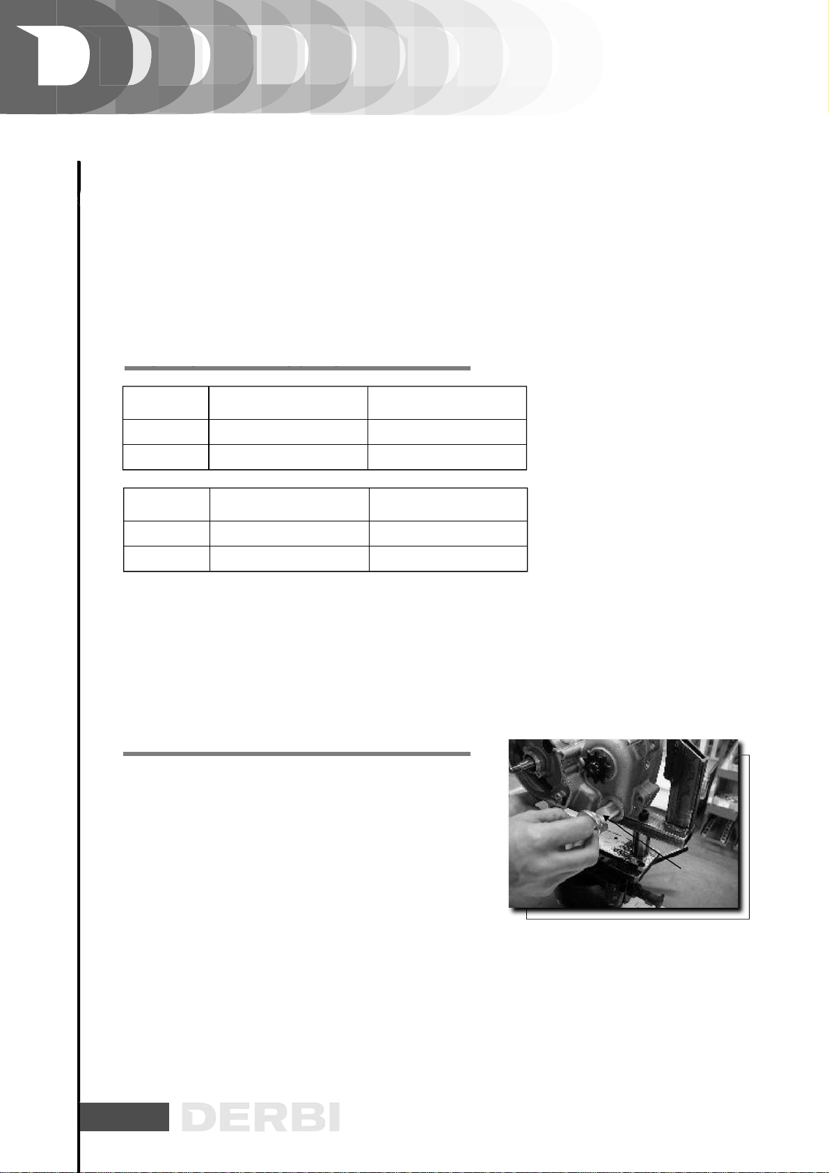
If the valve clearance values differ from those shown below
(for intake and exhaust respectively), proceed with the
adjustment, by loosening the counter nut and then, with the
aid of a screwdriver, loosening or tightening the adjusting
screw as shown in the figure.
CHARACTERISTIC
Valves play:
induction 0,10mm (cold)
Valves play:
exhaust 0,15mm (cold)
Locking torques (N*m)
Rocker-arm adjusting nuts: 7 ÷ 9 Nm
12
Page 13

CO
SSU
MAINTENANCE
MAINTENANCE
HECKING THE END
- With the engine cold, remove the spark plug cap.
- Remove the spark plug.
- Using a 10mm adapter, install a compression test manometer on the spark plug housing, and tighten at
the prescribed torque.
- Crank the engine using the starter motor and with the carburettor fully opened, as long as the manometer
reading has stabilized. If the pressure is within the prescribed limits, remove the manometer and refit the
components following the removal procedure in the reverse order.
- If the pressure is below the min allowable pressure, check the engine speed in test conditions. If this is too
low, check the starting system, if this is acceptable, or slightly faster, ensure the proper cylinder base gasket
is installed, and inspect the sealing of the thermal components (piston rings, valves, head, timing system,
etc.).
CHARACTERISTIC
Compression pressure
Min allowable value: 10,5 Kgr
MPRESSION PRE
RE
Engine revs:
~ 630 rpm (starting speed).
Locking torques (N*m)
Tightening torque ~ 10 ÷15 M m
13
Page 14

SMISSIO
CO
ENGINE
ENGINE
AUTOMATIC TRANSMISSION
TRAN
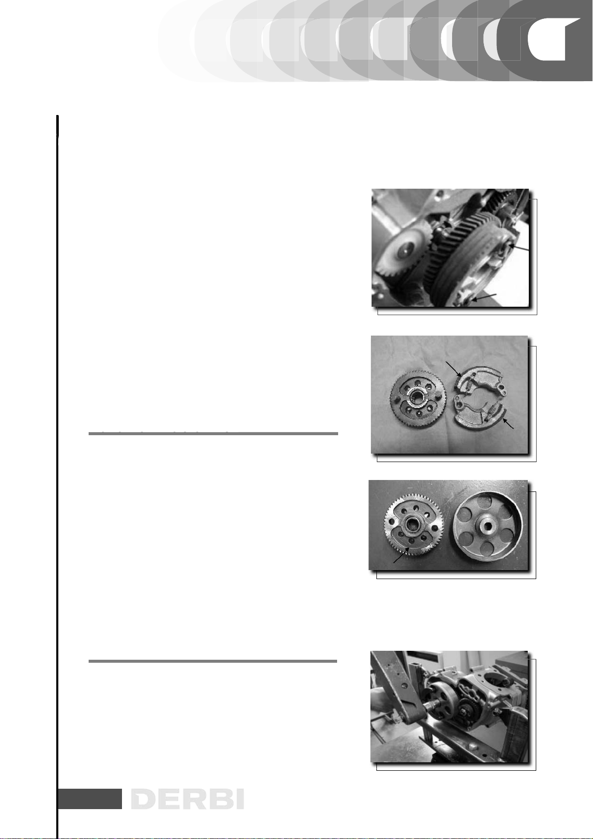
- Remove the seven cover fixing screws.
- Remove the screw and the kick-start.
- Remove the seeger ring and the washer shown in the figure.
- Remove the sector gear.
- Search for excessive wear in the toothed segment, the toothed
segment shaft, the gear shaft and its housing in the crankcase,
and the return spring.
- Replace any damaged part.
- Refit the toothed segment as show in the
figure, pre-loading the spring by hand.
N
VER
- Using the special tool, retain the engine gear shaft.
- Remove the lock nut and then the gear shaft.
Specific tooling
020288Y Gear shaft retaining tool
- Remove the clutch masses with their gear.
- Remove the two circlips so to free the clutch masses.
- Ensure the teeth are not deformed and/or worn.
14
Page 15
ENGINE
ENGINE
- Check the thickness of the friction material of the masses.
If the friction material of the mass is found to be missing
the circumferential grooves or cleats, the clutch is to
be considered excessively worn and the masses should
therefore be replaced.
N.B.
WHILE RUNNING-IN, THE MASSES SHOULD SHOW A
CENTRAL CONTACT SURFACE AND MUST DIFFER ONE
FROM THE OTHER. DIFFERENT CONDITIONS MAY CAUSE
A CLUTCH GRABBING PHENOMENON.
CAUTION
DO NOT USE TOOLS TO OPEN THE MASSES, SO TO AVOID
LOAD VARIATIONS IN THE SPRINGS.
- Check that the clutch bell housing is not worn or
damaged.
- Measure the inside diameter of the clutch bell housing.
N.B.
CHECK THE ECCENTRICITY OF THE CLUTCH DRUM AND
ITS KEYING: M AX 0.15 mm.
CHARACTERISTIC
Standard value:
Ø 92 +0,2 -0 mm
Max allowable value:
Ø 92,3 mm
EMOVING THE CLUTCH
- Lock the clutch bell housing with the specific tool.
- Remove the nut, the clutch bell housing and the whole of
the driven pulley assembly.
Specific tooling
020565Y Compass fly wheel stop spanner
15
Page 16

ENGINE
ENGINE
- Before refitting the assembly, carefully grease the roller
bearing inside the gear housing.
- Refit the clutch assembly, the drum washer, and the nut
using the special tool.
-After refitting, ensure the drum spins freely.
Specific tooling
020565Y Compass fly wheel stop spanner
Locking torques (N*m)
Coppia di bloccaggio 40-44 Nm
Insert the chain gear shaft and secure with its circlip, as
shown in the figure.
- Refit the gasket (new).
- Refit the cover tightening the seven screws at the prescribed
torque.
- Refit the oil filler cap.
Locking torques (N*m)
Transmission cover fixing screw: 8 ÷ 10 Nm.
REMOVING THE HUB COVER
Remove the shroud by acting upon the four fittings, as shown
in the figure.
16
Page 17

G
ENGINE
ENGINE
SG
- Remove the two stator fixing screws as shown in the figure.
According to the versions (kick-start/electric). Locking
torques ( N*m)
Flywheel cover fixing screw: 2,5 - 3 Nm
LYWHEEL AND STARTIN
- Restrain the rotation of the flywheel using the special tool.
- Remove the M10X1.25 flanged nut.
- Extract the flywheel with the specially designed extractor.
Specific tooling
020565Y Compass fly wheel stop spanner.
Flywheel tool: 2-claw universal extractor.
Locking torques (N*m)
Flywheel nut 15 Nm
Removing the pick-up:
Remove the two pick-up screws, as shown in the figure.
17
Page 18

ENGINE
- CYLINDER ASSY. AND TIMING SYSTEM
ENGINE - CYLINDER ASSY. AND TIMING SYSTEM
-
Remove the four tappet cover fastenings; remove the cover
complete with the 0-ring.
N.B.
IN THE CASE OF LONG MILEAGE OR POOR MAINTENANCE,
CLEAN THE OIL BREATER TUBE.
- Remove the chain tensioner central screw, together with its
spring, washer and O-ring.
- Loosen the chain tensioner central screw and remove it
with the spring and the washer.
18
Page 19

ENGINE
- CYLINDER ASSY. AND TIMING SYSTEM
ENGINE - CYLINDER ASSY. AND TIMING SYSTEM
- Remove the tappet cover.
- Remove the central screw and the belleville washer shown
in the figure using the specific tool to lock camshaft ring
gear.
- Remove the camshaft drive pulley and the shim below it.
N.B.
TO FACILITATE THE REMOVAL OF THE CYLINDER HEAD
COMPONENTS, IT IS ADVISABLE TO BRING THE CRANKSHAFT TO THE TDC, AT THE END OF THE COMPRESSION
STROKE.
Specific tooling
020565Y Compass fly wheel stop spanner
Remove the bearing check screw shown in the figure.
Remove the camshaft complete with the bearing using the
specific tool shown in the figure.
Eject the bearing from the camshaft using the specific tool
and taking care to fit a screw on the camshaft so as to protect
the camshaft thread.
N.B.
WHENEVER THE BEARING IS SEPARATED FROM THE
CAMSHAFT, REPLACE IT WITH A NEW ONE.
19
Page 20

ENGINE
- CYLINDER ASSY. AND TIMING SYSTEM
ENGINE - CYLINDER ASSY. AND TIMING SYSTEM
Specific tooling
020450Y Camshaft fitting/removing tool
004499Y Bearing extractor
Remove the rocker arm pivot through the hole on the flywheel side and simultaneously remove the rocker arms.
N.B.
MARK THE INSTALLING POSITION OF EACH ROCKER ARM
SO AS TO AVOID FIT TING THE INTAKE ROCKER AR M IN
PLACE OF THE EXHAUST ROCKER ARM OR VICE VERSA.
- Remove the timing assembly, the camshaft, and the rockerarms.
- Remove the spark plug.
- Remove the two side fastenings shown in the figure.
- Loosen the four cylinder head locknuts in two or three
phases following a crosswise pattern.
- Remove the cylinder head, the two dowel bolts and the
gasket.
N.B.
SHOULD IT BE NECESSARY, THE HEAD MAY BE REMOVED
WITH THE CAM SHAFT AND RACOKERARM PIN. IT SHOULD
BE REMEMBERED, HOWEVER, THAT IT IS THEN NECESSARY
TO HOLD THE CHAIN IN PLACE WITH A METALLIC WIRE AND
CARRY OUT THE CHAIN ADJUSTMENT WHEN REFITTING,
AS DESCRIBED IN THE PARAGRAPH “REFITTING THE TIMING
COMPONENTS”.
- Ensure the chain correctly engages the timing gear-shaft
keyed to the crankshaft, on the flywheel-side.
20
Page 21

-
.
ENGINE
- CYLINDER ASSY. AND TIMING SYSTEM
ENGINE - CYLINDER ASSY. AND TIMING SYSTEM
OG C SO SS .
Using the specific tool with the part shown in the figure, remove the cotter halves, the caps and the springs from both
valves.
Specific tooling
020382Y Valve fitting/removing tool
EMOVING THE CYLINDER
- Remove the cylinder minding the aligning pin on the crankcase.
- Remove the cylinder base gasket.
CAUTION
TO AVOID DAMAGING THE PISTON, SUPPORT IT WHILE
REMOVING THE CYLINDER.
- Remove the two circlips, the piston pin and the piston.
- Remove the three piston rings.
N.B.
TAKE CARE NOT TO DAMAGE THE PISTON RINGS WHILE
REMOVING THEM.
PISTON ASSY
21
Page 22

N
SC G S
SC G S
ENGINE
- CYLINDER ASSY. AND TIMING SYSTEM
ENGINE - CYLINDER ASSY. AND TIMING SYSTEM
NSPECTING THE SMALL END
Using an inside micrometer, measure the small end diameter.
N.B.
IF THE DIAMETER OF THE SMALL END IS GREATER THAN
THE MAX ALLOWABLE DIAMETER, OR SHOWS SIGNS OF
WEAR OR OVERHEAT, REPLACE THE CRANKSHAFT.
CHARACTERISTIC
Standard diameter:
13+0,025+0,015 mm
Max. allowable diameter:
13,030mm
NSPECTING THE WRIST PI
Measure the piston pin outside diameter.
CHARACTERISTIC
Standard diameter:
13-0 -0,0 0 4 mm
Minimum allowable diameter:
12,990 mm
Calculate the mating play between the piston pin and the
piston.
CHARACTERISTIC
Piston standard diameter:
13+0,010+0,005 mm
Fitting clearance
Wrist-pin/piston fitting clearance (standard): 0,005 - 0,014 mm
22
Page 23

SPEC
ON
ENGINE
- CYLINDER ASSY. AND TIMING SYSTEM
ENGINE - CYLINDER ASSY. AND TIMING SYSTEM
- Measure the piston outside diameter perpendicularly to the
piston pin axis.
- Take the measurement 27 mm from the piston top as
shown in the figure.
CHARACTERISTIC
Piston diameter:
38,982 - 38,954
- Using a bore meter, measure the cylinder inside diameter
at three different heights in the directions shown in the figure.
- Check that the mating surface with the cylinder head is not
worn or distorted.
CHARACTERISTIC
Standard cylinder diameter:
39,024 - 38,996
Maximum allowable runout:
0,05 mm
Pistons and cylinders are classified according to diameter.
Mating is obtained by matching class letters (A-A, B-B, C-C,
D-D).
IN
- Fit a comparator on the specific tool and then place both
parts on a surface plate.
- Reset the comparator on the surface plate. While maintaining the resetting position, fit the tool to the cylinder and
fasten it with two nuts as shown in the figure.
- Rotate the crankshaft to the TDC (comparator rotation inversion point).
TING THE PIST
23
Page 24

ENGINE
- CYLINDER ASSY. AND TIMING SYSTEM
ENGINE - CYLINDER ASSY. AND TIMING SYSTEM
- Measure the piston protrusion compared to the head plane
and use the chart below, to determine the proper base gasket thickness. The proper base gasket thickness guarantees
the engine will run at the correct compression ratio.
- Remove the specific tool and the cylinder.
CHARACTERISTIC
Compression ratio:
11,5÷ 12,5:1
Cylinder height:
57,15 ± 0,15
Cylinder base gasket thickness:
0,5
Measured value: - 0,40 / - 0,25
Gasket thickness: 0,25 ± 0,05
Measured value: - 0,25 / - 0,05
Gasket thickness: 0,35 ± 0,05
- Carefully clean the piston ring grooves using an old piston
ring.
- Using a reed thickness gauge, measure the play between
the piston rings and the grooves as shown in the figure.
- If any play is found to be greater than specified in the table
below, replace the piston and the piston rings.
24
Page 25

ENGINE
- CYLINDER ASSY. AND TIMING SYSTEM
ENGINE - CYLINDER ASSY. AND TIMING SYSTEM
STANDARD MATING PLAY
NAME
1º Ring
2º Ring
Scraper
DIMENSIONS
0,030 ÷ 0,065 mm
0,020 ÷ 0,055 mm
0,040 ÷ 0,160 mm
MAXIMUM ALLOWABLE PLAY AFTER USE
NAME
1º Ring
2º Ring
Scraper
DIMENSIONS
0,080 mm
0,070 mm
0,20 mm
INITIALS
INITIALS
QUANTITY
QUANTITY
- Alternately insert the three piston rings into the cylinder, in
the area where it retains its original diameter.
- Using the piston, insert the rings perpendicularly to the
cylinder axis
- Using a thickness gauge (see figure), measure the gaps of
the piston rings.
- If any measurements are greater than prescribed, replace
the piston rings.
25
Page 26

ENGINE
- CYLINDER ASSY. AND TIMING SYSTEM
ENGINE - CYLINDER ASSY. AND TIMING SYSTEM
N.B.
BEFORE REPLACING THE PISTON RINGS ONLY, ENSURE
THAT THE CLEARANCE BETWEEN THE PISTON RINGS AND
THE PISTON RING GROOVES, AND BETWEEN THE PISTON
AND THE CYLINDER, IS AS SPECIFIED. IN ANY CASE, NEW
PISTON RINGS USED IN COMBINATION WITH A USED CYLINDER MAY HAVE DIFFERENT BEDDING CONDITIONS THAN
THE STANDARD.
STANDARD GAP
NAME
1º Ring
2º Ring
Scraper
MAXIMUM GAP
NAME
1º Ring
2º Ring
Scraper
DIMENSIONS
0,08 ÷ 0,20 mm
0,05 ÷ 0,20 mm
0,20 ÷ 0,70 mm
DIMENSIONS
0,35 mm
0,30 mm
0,8 mm
INITIALS
INITIALS
QUANTITY
QUANTITY
26
Page 27

ENGINE
- CYLINDER ASSY. AND TIMING SYSTEM
ENGINE - CYLINDER ASSY. AND TIMING SYSTEM
- Fit the piston and the piston pin to the connecting rod. The
arrow on the piston must face the exhaust side.
- Insert the piston pin circlip into the specially designed tool.
- With the gap in the position shown on the tool, fit the circlip
into the tool by means of the drift.
- Rest the tool on the piston taking care that the side with the
90° bevel always faces upwards as shown in the figure.
- Fit the piston pin circlip using the tommy.
CAUTION
USING A HAMMER TO FIT THE CIRCLIPS CAN DAMAGE THE
CIRCLIP SEATS.
Specific tooling
0204484YIIK Piston pin circlip fitting tool
27
Page 28

ENGINE
- CYLINDER ASSY. AND TIMING SYSTEM
ENGINE - CYLINDER ASSY. AND TIMING SYSTEM
- Fit the scraper starting with the spring. Ensure that the scraper ends do not overlap.
- Fit the two piston rings so that their gaps and that of the
scraper are never aligned.
- Fit the 2nd piston ring with the identification letter «T» facing the piston top.
- Fit the 1st piston ring with the «T» reference mark facing
the piston top.
N.B.
TO ENSURE OPTIMUM BEDDING, THE TWO PISTON RINGS
HAVE CONICAL SECTIONS IN THE AREAS OF CONTACT
WITH THE CYLINDER. FOR THIS REASON, IT IS IMPORTANT
THAT THE RINGS SHOULD BE FITTED WITH THE «T» FACING
UPWARDS. STAGGER THE PISTON RING GAPS BY 120 DEGREES AS SHOWN IN THE FIGURE. LUBRICATE THE PARTS
WITH ENGINE OIL.
Install the base gasket with the previously determined thickness. Carry out the refitting procedure for the cylinder as
shown in the figure.
Ensure to drive the timing chain through its housing while
maintaining it engaged on the timing gearshaft.
CHARACTERISTIC
Cylinder base gasket thickness:
0,5
28
Page 29

ENGINE
- CYLINDER ASSY. AND TIMING SYSTEM
ENGINE - CYLINDER ASSY. AND TIMING SYSTEM
N.B.
SEE “REFITTING THE TIMING CHAIN”, TO BE CARRIED OUT
BEFORE RECOUPLING THE HALFCR ANKCASES.
- Insert the spacer on the camshaft.
- Using the markings on flywheel and stator mounting bracket, position the piston at the TDC.
- Insert the chain tensioning rod and secure it in its housing.
It is possible to hold the piston out of the crankcase plane,
using the special tool.
N.B.
BEFORE REFITTING THE CYLINDER, CAREFULLY BLOW THE
LUBRICATION DUCT AND OIL THE CYLINDER BARREL.
Specific tooling
020288Y Fork for fitting piston to cylinder
Locking torques (N*m)
Timing chain tensioner screw: 8 ÷ 10 Nm
NSPECTING THE CYLINDER HEAD
Using a trued bar, check that the cylinder head surface is not
worn or distorted.
CHARACTERISTIC
Maximum allowable runout:
0,05 mm
- Ensure that the camshaft and rocker arm pivot bearings
show no signs of wear.
- Check that the cylinder head cover surface, the intake manifold and the exhaust manifold are not worn.
29
Page 30

ENGINE
- CYLINDER ASSY. AND TIMING SYSTEM
ENGINE - CYLINDER ASSY. AND TIMING SYSTEM
STANDARD DIAMETER
SPECIFICATIONS
Standrad diameter A:
Standrad diameter B:
Standrad diameter C:
- Check that the guide shoe and the tensioner shoe are not
worn out.
DESC. / QUANTITY
Ø 32,015 ÷ 32,025 mm
Ø 16,0 ÷ 16,018 mm
Ø 11,0 ÷ 11,018 mm
- Ensure that the camshaft drive pulley, the chain assembly
and the pinion are not worn.
- Replace any worn components. If the chain, pinion or
pulley are worn, replace the whole assembly.
- Removing the central screw with the O-ring and the chaintensioner spring. Ensure the unidirectional mechanism is not
worn.
- Check the condition of the tensioner spring.
- If any worn components are found, replace the whole
assembly.
30
Page 31

ENGINE
- CYLINDER ASSY. AND TIMING SYSTEM
ENGINE - CYLINDER ASSY. AND TIMING SYSTEM
Measure the width of the sealing surface on the valve seats.
CHARACTERISTIC
Sealing surface width
Intake: 1,5 m m
Exhaust: 1,6 m m
- Remove any carbon formation from the valve guides.
- Measure the inside diameter of each valve guide.
- Take the measurement at three different heights in the rocker arm push direction.
EXHAUST GUIDE
SPECIFICATION
Standard diameter:
Wear limit:
INTAKE GUIDE
SPECIFICATION
Standard diameter:
Wear limit:
- If the width of the impression on the valve seat or the diameter of the valve guide exceed the prescribed limits, replace the cylinder head.
- Measure the width of the impression on valve seat «V», the
wear limit being 1.6 mm.
DESC. / QUANTITY
5 + 0 + 0,012 mm
5,022 mm
DESC. / QUANTITY
5 + 0 + 0,012 mm
5,022 mm
31
Page 32

ENGINE
- CYLINDER ASSY. AND TIMING SYSTEM
ENGINE - CYLINDER ASSY. AND TIMING SYSTEM
- Insert the valves into the cylinder head.
- Alternately test the intake and exhaust valves.
- The test is carried out by filling the manifold with petrol and
checking that no petrol oozes through the valves when these
are pressed with one finger.
- Measure the diameter of the valve stem at the three positions shown in the figure.
- Calculate the clearance between the valve and the valve
guide.
- Check that the mating surface with the adjuster articulated
terminal is not worn.
- Should the valve sealing area be greater than the prescribed limit, or if any bending or gaps are noted, replace the
valve.
- If no anomalies are found during the above checks, the
same valves can be reused.
- For best sealing results, it is advisable to grind the valves.
- Grind the valves gently with a fine-grained lapping compound.
- During the grinding, keep the cylinder head in a horizontal
position. This will prevent the lapping compound residues
from penetrating between the valve stem and the guide.
CAUTION
TO AVOID SCORING THE MATING SURFACE, DO NOT KEEP
ROTATING THE VALVE WHEN NO LAPPING COMPOUND
IS LEFT. CAREFULLY WASH THE CYLINDER HEAD AND THE
VALVES WITH A SUITABLE PRODUCT FOR THE TYPE OF LAPPING COMPOUND BEING USED.
32
Page 33

ENGINE
- CYLINDER ASSY. AND TIMING SYSTEM
ENGINE - CYLINDER ASSY. AND TIMING SYSTEM
CHARACTERISTIC
Minimum allowable diameter - Intake:
4,970 mm
Minimum allowable diameter - Exhaust:
4,960 mm
Standard clearance - Intake:
0,015 ÷ 0,042 mm
Standard clearance - Exhaust:
0,025 ÷ 0,052 mm
Maximum allowable clearance - Intake:
0,052 mm
Maximum allowable clearance - Exhaust:
0,062 mm
Valve standard length - Intake:
70,1 mm
Valve standard length - Exhaust:
69,2 mm
-
Check that the upper spring caps and the cotter halves show
no signs of abnormal wear.
- Lubricate the valve guides with graphitized oil.
- Position the valve spring lower caps on the cylinder head.
- Using the specific drift, alternately insert the two seal
rings.
- Fit the valves, the springs and the upper caps.
- Using the specific tool, compress the springs and insert the
cotter halves into their seats.
Specific tooling
020306Y Valve oil seal fitting drift
020382Y Valve fitting/removing tool
33
Page 34

ENGINE
- CYLINDER ASSY. AND TIMING SYSTEM
ENGINE - CYLINDER ASSY. AND TIMING SYSTEM
- Ensure that the camshaft bearings are not abnormally
worn.
- If any measurements or values are not as specified, proceed to replace the defective parts.
N.B.
A BALL BEARING IS PITTED ON BEARING «A»; CONSEQUENTLY, BEARING «B» IS MORE IMPORTANT BECAUSE IT
WORKS DIRECTLY ON THE ALUMINIUM OF THE CYLINDER
HEAD.
CHARACTERISTIC
Standard diameter - Bearing A:
Ø 12+0,002+0,010 mm
Standard diameter - Bearing B:
Ø 16-0,015-0,023mm
Minimum allowable diameter - Bearing A:
Ø 11,98mm
Minimum allowable diameter - Bearing B:
Ø 15,96 mm
Standard height - Intake:
25,935 mm
Standard height - Exhaust:
25,935 mm
Maximum allowable axial play:
0,5 mm
- Ensure that the rocker arm pivot is not worn or scored.
- Measure diameter «A».
- Measure the inside diameter of each rocker arm «B».
- Check that the cam contact shoe and the adjuster articulated cap are not worn.
34
Page 35

ENGINE
- CYLINDER ASSY. AND TIMING SYSTEM
ENGINE - CYLINDER ASSY. AND TIMING SYSTEM
- Replace any damaged parts.
CHARACTERISTIC
Minimum allowable diameter «A»:
Ø 10,970mm
Minimum allowable diameter «B»:
Ø 11,030 mm
- Rest the cylinder head steadily on a worktable.
- Screw on the camshaft fitting tool to its abutting end on the
bearing inner race.
- Push the camshaft in its housing, fitted with the bearing, as
far as it goes. Remove the tool.
- After having carefully cleaned all the contact surfaces,
install a new head gasket with the same thickness as the old
one.
- Insert the cylinder holding-down studs into the cylinder
head and tighten the four locknuts with a torque indicate.
N.B.
REPLACE THE CAMSHAFT BEARING WITH A NEW ONE
WHENEVER IT IS REMOVED.
Specific tooling
020450y Camshaft fitting/removing tool
Locking torques (N*m)
Head-cylinder stud nut:
6-7 +135° +90° N-m for first fitting, 6 - 7 90° +90° N-m for
refitting/locking
- Loosen the rocker arm adjusters.
- Fit the pivot and the intake and exhaust rocker arms.
- Lubricate the two rocker arms through the holes.
35
Page 36

ENGINE
- CYLINDER ASSY. AND TIMING SYSTEM
ENGINE - CYLINDER ASSY. AND TIMING SYSTEM
- Tighten the pivot and camshaft check screw complete with
the washer shown in the figure.
Locking torques (N*m)
Rocker-arm shaft and camshaft bearing screw: 3 - 4 Nm
- To complete the fastening of the cylinder head, tighten the
four cylinder head nuts in two phases in a crosswise pattern
to a torque of 8 -10 N-m.
- Lock with the same torque used for the two side fixings.
- Continue tightening the nuts by giving them three 90-degree turns, following in a crosswise pattern. First locking: 6
- 7 Nm +135° +90° Relocking: 6 - 7 Nm +90° +90°FoIlowing the order indicated
N.B.
SEE “REFITTING THE TIMING CHAIN”, TO BE CARRIED OUT
BEFORE RECOUPLING THE HALFCR ANKCASES.
- Insert the spacer on the camshaft.
- Using the markings on flywheel and stator mounting bracket, position the piston at the TDC.
- Insert the chain tensioning rod and secure it in its housing.
- Ensure the chain correctly engages the timing gear-shaft
keyed to the crankshaft, on the flywheel-side.
- While keeping the piston in position, fit the chain on the
camshaft drive pulley, while maintaining the reference notch
aligned with the mark on the cylinder head.
36
Page 37

ENGINE
- CYLINDER ASSY. AND TIMING SYSTEM
ENGINE - CYLINDER ASSY. AND TIMING SYSTEM
- Fit the pulley on the camshaft.
- Fit the belleville washer so that its outer rim is in contact
with the pulley.
- Turn in the screw until it makes contact, without tightening
it fully.
- Slightly press the tensioner shoe to verify the valve gear
timing.
- Using the specific tool, lock the camshaft ring gear and
then tighten the screw.
- Carry out the valve clearance adjustment procedure as
described in the «lnspecting/adjusting the valve clearance»
paragraph.
- Replace the 0-ring on the tappet cover.
- Fit the tappet cover and fasten it using the four fixing screws
shown in the figure.
Specific tooling
020565Y Compass fly wheel stop spanner
Locking torques (N*m)
Camshaft pulley screw:
12 - 14 Nm Head cover screw: 8-10 Nm
- Set the tensioner slider in its home position.
- Install the tensioner on the cylinder using a new gasket;
hence tighten the screws with the prescribed torque.
- Insert the spring with the central screw and the O-ring,
hence tighten the cap with the prescribed torque.
- Fit the spark plug.
CHARACTERISTIC
Recommended spark plug
Champion RG 4 HC
Electric characteristic
Electrode gap
mm 0,7 ÷ 0,8
Locking torques (N*m)
Timing chain tensioner screw:
8 ÷ 10 Nm
Timing chain tensioner central screw:
5 ÷ 6 Nm
Spark plug:
10 ÷ 15 Nm
37
Page 38

P
ENGINE
- CYLINDER ASSY. AND TIMING SYSTEM
ENGINE - CYLINDER ASSY. AND TIMING SYSTEM
SC G G
NSPECTING THE RADIAL AIR GA
Inspecting the kick-starter:
- Using a thickness gauge, measure the two metallic protrusions. Values: 0.2 ÷ 0.3 mm.
- Ensure the pick-up air is between 2.0 and 2.6 mm
- The pick-up refitting procedure does not include the adjustment of the air gap.
- Values different from the above, are due to deformations of
the pick-up mounting bracket.
Locking torques (N*m)
Stator/mounting bracket fixing screws: (M4x16) 2 ÷ 3 Nm
Pick-up/flywheel-side halfcrankcase fixing screws: (M6x16)
8 ÷ 10 Nm Mounting bracket for stator assy ./flywheel-side
half-crankcase fixing screws: (M6x20) 8 ÷ 10 Nm Flywheel fixing flanged-nut: (M10x1,25) 15 Nm Flywheel cover/
flywheel-side half-crankcase fixing screw: (M5x20) 2,5 ÷
3 Nm.
Follow the removal operations in the reverse order, tightening the four screws with the prescribed torque.
N.B.
FIT A NEW 0-RING ON THE ROCKER-ARMS COVER.
Locking torques (N*m)
Head cover screw: 8 ÷ 10 Nm
38
Page 39

ENGINE
- CRANKCASE - CRANKSHAFT
ENGINE - CRANKCASE - CRANKSHAFT
- Remove the following assemblies: Transmission cover,
clutch, gears, as described in the related paragraphs: «Removing the transmission cover», «Removing the clutch», and
«Removing the gear-shafts.
- For kick-start versions, remove the flywheel shroud, the
flywheel, the stator mounting, and the pick-up, as described
in the related paragraphs «Removing the flywheel shrouds,
«Removing the fly wheel magnetos, and «Removing the stator».
- For electric starter versions, remove the Bendix mounting
and the starter motor as described in the paragraph «Removing the starter motors.
- Remove the cylinder-piston-head assembly as described in
the related paragraphs.
- Remove the ten half-crankcase coupling screws. Split the
crankcase-halves, with the crankshaft remaining installed in
the flywheel-side half.
- Remove the crankshaft, by heating the halfcrankcase up to
about 120 °C with the aid of a heat gun.
N.B.
MIND THE LOOSE COMPONENTS INSIDE THE CR ANKCASE: CLUTCH SHAFT, TIMING CHAIN GEAR-SHAFT, AND
TWO REFERENCE PINS.
- Remove the flywheel-side oil seal from the crankcase,
paying attention in avoiding scratching or scoring the crankcase.
- Abundantly lubricate the new oil seal and its housing on
the crankcase with engine oil, before fitting.
- Position the crankshaft on the base of the support.
- Install the bearing.
- Using the special tool, refit the timing gearshaft.
39
Page 40

ENGINE
- CRANKCASE - CRANKSHAFT
ENGINE - CRANKCASE - CRANKSHAFT
ALIGNMENT
- Rest the flywheel-side crankcase-half on a flat surface,
adequately supported and with the crankshaft vertical.
- Insert the timing chain positioning it at the edge of its
housing so that in won’t interfere with the refitting of the
crankshaft assembly, the bearing, and the timing gearshaft.
- Heat the crankcase-half up to approx. 120 °C, using a heat
gun.
- Install the bearing on the crankcase with utmost care in
order to avoid damaging the bearing housing.
Place the crankshaft on the stand and measure the runout at
the three points shown in the figure.
Check the condition of the crankshaft cone, the tab seat, the
oil seal bearing, the knurled pin and the threaded tangs. If
any anomalies are found, replace the crankshaft.
NB
IF THE RUNOUT MEASUREMENTS SLIGHTLY EXCEED THE
SPECIFIED LIMITS, TRY TO STR AIGHTEN THE CRANKSHAFT
BY INSERTING A WOODEN WEDGE BETWEEN THE SHAFTS
OR, IF NECESSARY, BY CLAMPING THEM IN A VICE. IF,
DESPITE THE STR AIGHTENING, THE VALUES ARE NOT AS
SPECIFIED, PROCEED TO REPLACE THE CRANKSHAFT.
Specific tooling
020074Y Crankshaft aligning tool
020335Y Magnetic stand and comparator
CHARACTERISTIC
Max allowable misalignments:
A = Ø 0,05 mm
B = Ø 0,04 mm
C = Ø 0,04 mm
40
Page 41

ENGINE
- CRANKCASE - CRANKSHAFT
ENGINE - CRANKCASE - CRANKSHAFT
- Check the connecting rod axial play.
- While holding the crankshaft manually, check the connecting rod radial play. Measure the play with a comparator placed on the tip of the connecting rod small end while moving
the connecting rod vertically as shown in the figure.
- Check that the surface of both crankshaft halves is not scored. Using a calliper, measure the width of the crankshaft as
shown in the figure.
CHARACTERISTIC
Standard crankshaft width:
Fitting clearance
45 mm
Standard axial clearance:
0,15-0,30 mm
Standard radial clearance:
0,006 - 0,018 mm
Max allowable radial clearance:
0,25 mm
41
Page 42

ENGINE
- CRANKCASE
ENGINE - CRANKCASE
- Using a heat gun, heat the bearing housing on the
transmission-side crankcase-half up to approximately 120
°C. Install the bearing and the oil conveying plate with its
gasket, tightening the three screws at the prescribed torque,
as shown in the figure. Install the clutch shaft bearing and
secure with the circlip, as indicated in the figure.
Pay attention in positioning the clutch shaft and the chain
gear-shaft.
- Refit the oil pump on the crankcase and secure it by
tightening the two screws with the prescribed torque.
- Install the two locating pins, preferably on the transmissionside crankcase-half.
- Lubricate the housings with the engine oil as shown in the
figure. Install the gasket using the two pins as a reference.
- Adjoin the two crankcase-halves and tighten the ten screws
with the prescribed torque.
Locking torques (N*m)
Oil conveying plate fixing screws (half-crankcase transmission
side): 8 ÷ 10 Nm
Oil pump / crankcase fixing screws: 2 ÷ 3 Nm
42
Page 43

ENGINE
- CRANKCASE
ENGINE - CRANKCASE
- Lubrificare con olio motore Ie rispettive sedi come
indicate in figura. Montare la guarnizione utilizzando come
riferimento i due grani.
- Accostare i due carter e montare Ie 10 viti e bloccare alia
coppia prescritta.
Locking torques (N*m)
Half-crankcase joining screws: 8 ÷ 10 Nm
43
Page 44

ENGINE
- OIL PUMP
ENGINE - OIL PUMP
CRANKSHAFT OIL SEALS
Removal
- Extract the flywheel-side oil seal from the crank- case
taking care not to damage or score the crankcase.
- Pour engine oil over the oil seal and its seat in the
crankcase.
- Operating from the outside with the specific drift, push the
oil seal fully home into its seat in the crankcase.
Specific tooling
020340Y Fly wheel-side oil seal fitting drift Oil pump
INSPECTION
- Remove the two oil pump fixing screws.
- Remove the inner rotor circlip.
- Remove the rotors and carefully clean them with a
degreasing solvent and compressed air.
- Refit the two impellers with pump body and install the
circlip.
Using a thickness gauge, measure the distance between the
rotors (inner rotor - outer rotor) at the position shown in the
figure.
CHARACTERISTIC
Maximum allowable clearance:
0,15 mm
44
Page 45

ENGINE
- OIL PUMP
ENGINE - OIL PUMP
Measure the distance between the outer rotor and the pump
body (see figure).
CHARACTERISTIC
Maximum allowable clearance:
0,20 mm
Check the axial play of the rotors using a trued bar as shown
in the figure.
N.B.
ENSURE THAT THE TRUED BAR RESTS PROPERLY ON TWO
POINTS OF THE PUMP BODY PLANE.
CHARACTERISTIC
Maximum allowable clearance:
0,09 mm
- Check that the pump cover is not worn or scored.
- If any measurement is not as specified, or if any part is
scored, replace the part or the assembly.
- Fit the oil pump to the crankcase and tighten the two fixing
screws with the prescribed torque.
- Ensure that the pulley rotates smoothly, with no jerks or
friction.
Locking torques (N*m)
Oil pump / crankcase fixing screws:
2 ÷ 3 Nm
45
Page 46

ENGINE
- CARBURETTOR
ENGINE - CARBURETTOR
REMOVING THE CARBURETTOR
- In order to detach the carburettor from the engine, loosen
the intake manifold and reed-valve pipe clamp screw.
- To carry out further operations on the carburettor, disconnect the throttle cable and the fuel supply tube.
- Loosen the two fixing screws indicated in the figure and
remove the float bowl with its seal.
- Remove the jets (main and idling) and ensure they are not
obstructed.
- Remove the float with the fuel needle.
- Remove the throttle valve cover, paying attention to the
attached components (throttle valve, conical needle, and
return spring).
CAUTION
DO NOT ATTEMPT REMOVING COMPONENTS ATTACHED
TO THE CARBURETTOR BODY, SUCH AS: FUEL SUPPLY
DUCT, NEEDLE HOUSING, STARTER JET, AND ATOMISER.
- Before refitting the carburettor, carefully clean the carburettor body with a degreasing solvent and compressed air.
- Pay special attention to the fuel intake duct and the needle
seat.
- Wash and carefully blow the idling and main jets, the starter jet on the float bowl, the throttle valve, and the conical
needle.
46
Page 47

ENGINE
- CARBURETTOR
ENGINE - CARBURETTOR
- Should anomalies be observed for these components, proceed with the replacement.
- Refit the throttle valve cover.
- Refit the main and idling jets.
- Refit the float and its conical needle.
- Refit the float bowl ensuring the seal is properly positioned
in its housing.
WARNING
TO AVOID DAMAGE, DO NOT INSERT METAL OBJECTS IN
THE CALIBRATED SECTIONS.
ADJUSTING THE CARBURETTOR
Main jet
Minimum jet
Position-needle
Emulsifier
Air Screw
80
32
A-2 at the 2nd
210 GA
2 Turns
47
Page 48

create by: www.ciandisseny.com
 Loading...