


 ROBOT
ROBOT
RC5 CONTROLLER
INTERFACE MANUAL
Copyright © DENSO WAVE INCORPORATED, 2002
All rights reserved. No part of this publication may be reproduced in any form or by any means without permission in writing from the publisher.
Specifications are subject to change without prior notice.
All products and company names mentioned are trademarks or registered trademarks of their respective holders.

Preface
Thank you for purchasing this high-speed, high-accuracy assembly robot.
This manual covers interfacing required when you integrate your robot system configured with the RC5 robot controller into your facilities.
Before use, read this manual carefully together with related manuals to safely get the maximum benefit from your robot in your assembling operations.
Robot models covered by this manual
All robot models configured with RC5 controller
Important
To ensure operator safety, be sure to read the precautions and instructions in "SAFETY PRECAUTIONS."
i
How the documentation set is organized
The documentation set consists of the following books. If you are unfamiliar with this robot and option(s), please read all books and understand them fully before operating your robot and option(s).
GENERAL INFORMATION ABOUT ROBOT
Provides the packing list of the robot and outlines of the robot system, robot unit, and robot controller.
INSTALLATION & MAINTENANCE GUIDE
Provides instructions for installing the robot components and customizing your robot, and maintenance & inspection procedures.
BEGINNER'S GUIDE
Introduces you to the DENSO robot. Taking an equipment setup example, this book guides you through running your robot with the teach pendant, making a program in WINCAPSII, and running your robot automatically.
SETTING-UP MANUAL
Describes how to set-up or teach your robot with the teach pendant, operating panel, or mini-pendant.
WINCAPSII GUIDE
Provides instructions on how to use the teaching system WINCAPSII which runs on the PC connected to the robot controller for developing and managing programs.
PROGRAMMER'S MANUAL (I), (II)
Describes the PAC programming language, program development, and command specifications in PAC.
RC5 CONTROLLER
INTERFACE MANUAL - this book -
Describes the RC5 controller, interfacing with external devices, systemand user-input/output signals, and I/O circuits.
ERROR CODE TABLES
List error codes that will appear on the teach pendant, operating panel, or PC screen if an error occurs in the robot series or WINCAPSII. These tables provide detailed description and recovery ways.
OPTIONS MANUAL
Describes the specifications, installation, and use of optional devices.
ii
How this book is organized
This book is just one part of the robot documentation set. This book consists of SAFETY PRECAUTIONS and chapters one through nine.
SAFETY PRECAUTIONS
Defines safety terms and related symbols and provides precautions that should be observed. Be sure to read this section before operating your robot.
Chapter 1 Outline of the RC5 Controller
Provides an outline of the RC5 controller. The robot controller is available in several models that will differ in detailed specifications to match robot models to be connected.
Chapter 2 General Information about the Interface
Introduces you to the interface required for connecting the robot controller with a PLC or other external equipment. It describes two I/O allocation modes available--standard mode and compatible mode, and the switching procedure between those modes.
Describes declaration of I/O variables and user I/O signals.
Chapter 3 System I/O Signals in Standard Mode
Describes system I/O signals available in standard mode, and describes I/O signals that execute I/O commands.
Chapter 4 System I/O Signals in Compatible Mode
Describes the functions, terminal numbers, and on/off conditions of system I/O signals in compatible mode.
Chapter 5 I/O Circuits and Connectors (NPN type)
Describes the I/O circuits and connector pin layout of an NPN I/O board (source input and sink output). The NPN I/O board is designed for the use in Japan.
Chapter 6 I/O Circuits and Connectors (PNP type)
Describes the I/O circuits and connector pin layout of a PNP I/O board (sink input and source output).
Chapter 7 I/O Wiring
Describes I/O cables and wiring.
iii

SAFETY PRECAUTIONS
SAFETY PRECAUTIONS
Be sure to observe all of the following safety precautions.
Strict observance of these warning and caution indications are a MUST for preventing accidents, which could result in bodily injury and substantial property damage. Make sure you fully understand all definitions of these terms and related symbols given below, before you proceed to the text itself.
WARNING |
Alerts you to those conditions, which could result |
|
|
|
in serious bodily injury or death if the instructions |
|
are not followed correctly. |
|
|
CAUTION |
Alerts you to those conditions, which could result |
|
in minor bodily injury or substantial property |
|
damage if the instructions are not followed |
|
correctly. |
|
|
Terminology and Definitions
Maximum space: Refers to the volume of space encompassing the maximum designed movements of all robot parts including the end-effector, workpiece and attachments. (Quoted from the RIA* Committee Draft.)
Restricted space: Refers to the portion of the maximum space to which a robot is restricted by limiting devices (i.e., mechanical stops). The maximum distance that the robot, end-effector, and workpiece can travel after the limiting device is actuated defines the boundaries of the restricted space of the robot. (Quoted from the RIA Committee Draft.)
Motion space: Refers to the portion of the restricted space to which a robot is restricted by software motion limits. The maximum distance that the robot, end-effector, and workpiece can travel after the software motion limits are set defines the boundaries of the motion space of the robot. (The "motion space" is DENSO WAVE-proprietary terminology.)
Operating space: Refers to the portion of the restricted space (or motion space in Denso robot) that is actually used by the robot while performing its task program. (Quoted from the RIA Committee Draft.)
Task program: Refers to a set of instructions for motion and auxiliary functions that define the specific intended task of the robot system. (Quoted from the RIA Committee Draft.)
(*RIA: Robotic Industries Association)

1.Introduction
2.Installation Precautions
This section provides safety precautions to be observed during installation, teaching, inspection, adjustment, and maintenance of the robot.
2.1Insuring the proper installation environment
2.1.1 |
For standard type |
The |
standard type has not been designed to withstand |
|
|
explosions, dust-proof, nor is it splash-proof. Therefore, it |
|
|
|
should not be installed in any environment where: |
|
|
|
(1) |
there are flammable gases or liquids, |
|
|
(2) |
there are any shavings from metal processing or other |
|
|
|
conductive material flying about, |
|
|
(3) |
there are any acidic, alkaline or other corrosive gases, |
|
|
(4) |
there is cutting or grinding oil mist, |
|
|
(5) |
it may likely be submerged in fluid, |
|
|
(6) |
there is sulfuric cutting or grinding oil mist, or |
|
|
(7) |
there are any large-sized inverters, high output/high |
|
|
|
frequency transmitters, large contactors, welders, or other |
|
|
|
sources of electrical noise. |
2.1.2 |
For dust-proof, splash- |
The |
dust-proof, splash-proof type is an IP54-equivalent |
|
proof type |
structure, but it has not been designed to withstand explosions. |
|
|
|
(The HS-E-W and the wrist of the VM-D-W/VS-E-W are an |
|
|
|
IP65-equivalent dust-proof and splash-proof structure.) |
|
|
|
Note that the robot controller is not a dustor splash-proof |
|
|
|
structure. Therefore, when using the robot controller in an |
|
|
|
environment exposed to mist, put it in an optional protective |
|
|
|
box. |
|
|
|
The dust-proof, splash-proof type should not be installed in any |
|
|
|
environment where: |
|
|
|
(1) |
there are any flammable gases or liquids, |
|
|
(2) |
there are any acidic, alkaline or other corrosive gases, |
|
|
(3) |
there are any large-sized inverters, high output/high |
|
|
|
frequency transmitters, large contactors, welders, or other |
|
|
|
sources of electrical noise, |
|
|
(4) |
it may likely be submerged in fluid, |
|
|
(5) |
there are any grinding or machining chips or shavings, |
|
|
(6) |
any machining oil not specified in this manual is in use, or |
|
|
|
Note: Yushiron Oil No. 4C (non-soluble) is specified. |
|
|
(7) |
there is sulfuric cutting or grinding oil mist. |
2.2 |
Service space |
The robot and peripheral equipment should be installed so that |
|
|
|
sufficient service space is maintained for safe teaching, |
|
maintenance, and inspection.

2.3Control devices outside the robot's restricted space
2.4Positioning of gauges
2.5Protection of electrical wiring and hydraulic/pneumatic piping
2.6Positioning of emergency stop switches
2.7Positioning of operating status indicators
SAFETY PRECAUTIONS
The robot controller, teach pendant, and operating panel should be installed outside the robot's restricted space and in a place where you can observe all of the robot’s movements when operating the robot controller, teach pendant, or operating panel.
Pressure gauges, oil pressure gauges and other gauges should be installed in an easy-to-check location.
If there is any possibility of the electrical wiring or hydraulic/pneumatic piping being damaged, protect them with a cover or similar item.
Emergency stop switches should be provided in a position where they can be reached easily should it be necessary to stop the robot immediately.
(1)The emergency stop switches should be red.
(2)Emergency stop switches should be designed so that they will not be released after pressed, automatically or mistakenly by any other person.
(3)Emergency stop switches should be separate from the power switch.
Operating status indicators should be positioned in such a way where workers can easily see whether the robot is on temporary halt or on an emergency or abnormal stop.

2.8Setting-up the safety fence or enclosure
2.9Positioning of rope or chain
A safety fence or enclosure should be set up so that no one can easily enter the robot's restricted space. If it is impossible, utilize other protectors as described in Section 2.9.
(1)The fence or enclosure should be constructed so that it cannot be easily moved or removed.
(2)The fence or enclosure should be constructed so that it cannot be easily damaged or deformed through external force.
(3)Establish the exit/entrance to the fence or enclosure. Construct the fence or enclosure so that no one can easily get past it by climbing over the fence or enclosure.
(4)The fence or enclosure should be constructed to ensure that it is not possible for hands or any other parts of the body to get through it.
(5)Take any one of the following protections for the entrance/ exit of the fence or enclosure:
1)Place a door, rope or chain across the entrance/exit of the fence or enclosure, and fit it with an interlock that ensures the emergency stop device operates automatically if it is opened or removed.
2)Post a warning notice at the entrance/exit of the fence or enclosure stating "In operation--Entry forbidden" or "Work in progress--Do not operate" and ensure that workers follow these instructions at all times.
When making a test run, before setting up the fence or enclosure, place an overseer in a position outside the robot’s restricted space and one in which he/she can see all of the robot’s movements. The overseer should prevent workers from entering the robot's restricted space and be devoted solely to that task.
If it is not possible to set up the safety fence or enclosure described in Section 2.8, hang a rope or chain around the perimeter of the robot’s restricted space to ensure that no one can enter the restricted space.
(1)Ensure the support posts cannot be moved easily.
(2)Ensure that the rope or chain’s color or material can easily be discerned from the surrounds.
(3)Post a warning notice in a position where it is easy to see stating "In operation--Entry forbidden" or "Work in progress --Do not operate" and ensure that workers follow these instructions at all times.
(4)Set the exit/entrance, and follow the instructions given in Section 2.8, (3) through (5).
2.10Setting the robot's motion space
2.11No robot modification allowed
2.12Cleaning of tools
2.13Lighting
SAFETY PRECAUTIONS
The area required for the robot to work is called the robot's operating space.
If the robot’s motion space is greater than the operating space, it is recommended that you set a smaller motion space to prevent the robot from interfering or disrupting other equipment.
Refer to the "INSTALLATION & MAINTENANCE GUIDE."
Never modify the robot unit, robot controller, teach pendant or other devices.
If your robot uses welding guns, paint spray nozzles, or other end-effectors requiring cleaning, it is recommended that the cleaning process be carried out automatically.
Sufficient illumination should be assured for safe robot operation.
2.14Protection from objects thrown by the endeffector
2.15Affixing the warning label
If there is any risk of workers being injured in the event that the object being held by the end-effector is dropped or thrown by the end-effector, consider the size, weight, temperature and chemical nature of the object and take appropriate safeguards to ensure safety.
Place the warning label packaged with the robot on the exit/entrance of the safety fence or in a position where it is easy to see.

|
|
|
|
|
|
|
3. Precautions |
|
Touching the robot while it is |
||||
while robot is |
|
|||||
Warning |
in operation |
|
can |
lead |
to |
|
running |
|
serious injury. Please ensure |
||||
|
|
the following |
conditions |
are |
||
|
|
maintained |
and |
that |
the |
|
|
|
cautions listed |
from Section |
|||
|
|
3.1 onwards |
are |
followed |
||
|
|
when any work is being |
||||
|
|
performed. |
|
|
|
|
1)Do not enter the robot's restricted space when the robot is in operation or when the motor power is on.
2)As a precaution against malfunction, ensure that an emergency stop device is activated to cut the power to the robot motor upon entry into the robot's restricted space.
3)When it is necessary to enter the robot's restricted space to perform teaching or maintenance work while the robot is running, ensure that the steps described in Section 3.3 "Ensuring safety of workers performing jobs within the robot's restricted space" are taken.
3.1 Creation of working |
When entering the robot’s restricted space to perform teaching |
|||
regulations and |
or maintenance inspections, set "working regulations" for the |
|||
assuring worker |
following items and ensure workers adhere to them. |
|||
(1) |
Operating procedures required to run the robot. |
|||
adherence |
||||
|
(2) |
Robot speed when performing teaching. |
||
|
(3) |
Signaling methods to be used when more than one worker |
||
|
|
is to perform work. |
||
|
(4) |
Steps that must be taken by the worker in the event of a |
||
|
|
malfunction, according to the contents of the malfunction. |
||
|
(5) |
The necessary steps for checking release and safety of the |
||
|
|
malfunction status, in order to restart the robot after robot |
||
|
|
movement has been stopped due to activation of the |
||
|
|
emergency stop device |
||
|
(6) |
Apart from the above, any steps below necessary to |
||
|
|
prevent danger from unexpected robot movement or |
||
|
|
malfunction of the robot. |
||
|
|
1) |
Display of the control panel (See Section 3.2 on the |
|
|
|
|
following page) |
|
|
|
2) |
Assuring the safety of workers performing jobs within |
|
|
|
|
the robot's restricted space (See Section 3.3 on the |
|
|
|
|
following page) |
|

3.2Display of operation panel
3.3Ensuring safety of workers performing jobs within the robot's restricted space
SAFETY PRECAUTIONS
3)Maintaining worker position and stance
Position and stance that enables the worker to confirm normal robot operation and to take immediate refuge if a malfunction occurs.
4)Implementation of measures for noise prevention
5)Signaling methods for workers of related equipment
6)Types of malfunctions and how to distinguish them
Please ensure "working regulations" are appropriate to the robot type, the place of installation and to the content of the work.
Be sure to consult the opinions of related workers, engineers at the equipment manufacturer and that of a labor safety consultant when creating these "working regulations".
To prevent anyone other than the worker from accessing the start switch or the changeover switch by accident during operation, display something to indicate it is in operation on the operating panel or teach pendant. Take any other steps as appropriate, such as locking the cover.
When performing jobs within the robot’s restricted space, take any of the following steps to ensure that robot operation can be stopped immediately upon a malfunction.
(1)Ensure an overseer is placed in a position outside the robot’s restricted space and one in which he/she can see all robot movements, and that he/she is devoted solely to that task.
QAn emergency stop device should be activated immediately upon a malfunction.
RDo not permit anyone other than the worker engaged for that job to enter the robot’s restricted space.
(2)Ensure a worker within the robot's restricted space carries the portable emergency stop switch so he/she can press it (the robot stop button on the teach pendant) immediately if it should be necessary to do so.

3.4Inspections before commencing work such as teaching
3.5Release of residual air pressure
3.6Precautions for test runs
3.7Precautions for automatic operation
Before starting work such as teaching, inspect the following items, carry out any repairs immediately upon detection of a malfunction and perform any other necessary measures.
(1)Check for any damage to the sheath or cover of the external wiring or to the external devices.
(2)Check that the robot is functioning normally or not (any unusual noise or vibration during operation).
(3)Check the functioning of the emergency stop device.
(4)Check there is no leakage of air or oil from any pipes.
(5)Check there are no obstructive objects in or near the robot’s restricted space.
Before disassembling or replacing pneumatic parts, first release any residual air pressure in the drive cylinder.
Whenever possible, have the worker stay outside of the robot's restricted space when performing test runs.
(1)At start-up
Before the robot is to be started up, first check the following items as well as setting the signals to be used and perform signaling practice with all related workers.
1)Check that there is no one inside the robot’s restricted space.
2)Check that the teach pendant and tools are in their designated places.
3)Check that no lamps indicating a malfunction on the robot or related equipment are lit.
(2)Check that the display lamp indicating automatic operation is lit during automatic operation.
(3)Steps to be taken when a malfunction occurs
Should a malfunction occur with the robot or related equipment and it is necessary to enter the robot's restricted space to perform emergency maintenance, stop the robot’s operation by activating the emergency stop device. Take any necessary steps such as placing a display on the starter switch to indicate work is in progress to prevent anyone from accessing the robot.

3.8 Precautions in repairs
4.Daily and periodical inspections
SAFETY PRECAUTIONS
(1)Do not perform repairs outside of the designated range.
(2)Under no circumstances should the interlock mechanism be removed.
(3)When opening the robot controller's cover for battery replacement or any other reasons, always turn the robot controller power off and disconnect the power cable.
(4)Use only spare tools specified in this manual.
(1)Be sure to perform daily and periodical inspections. Before starting jobs, always check that there is no problem with the robot and related equipment. If any problems are found, take any necessary measures to correct them.
(2)When carrying out periodical inspections or any repairs, maintain records and keep them for at least 3 years.
5.Management of floppy disks
(1)Carefully handle and store the "Initial settings" floppy disks packaged with the robot, which store special data exclusively prepared for your robot.
(2)After finishing teaching or making any changes, always save the programs and data onto floppy disks.
Making back-ups will help you recover if data stored in the robot controller is lost due to the expired life of the back-up battery.
(3)Write the names of each of the floppy disks used for storing task programs to prevent incorrect disks from loading into the robot controller.
(4)Store the floppy disks where they will not be exposed to dust, humidity and magnetic field, which could corrupt the disks or data stored on them.

|
|
|
Contents |
|
|
Preface |
......................................................................................................................................................... |
|
|
|
i |
How the ...................................................................................................documentation set is organized |
ii |
||||
How this .......................................................................................................................book is organized |
iii |
||||
SAFETY PRECAUTIONS |
|
||||
Chapter 1 General Information about RC5 Controller |
|
||||
1.1 .......................................................................................... |
Controller Model Name on Nameplate |
1 |
|||
1.2 ................................................................................. |
Names of the Robot Controller Components |
4 |
|||
1.3 ...................................................................................................... |
Robot Controller Specifications |
7 |
|||
1.4 .................................................................................................. |
Controller System Configuration |
11 |
|||
1.4.1 .................................................. |
Internal Circuits of the Controller (Typical configuration) |
11 |
|||
1.4.2 .................................................................................. |
Typical Robot System Configurations |
12 |
|||
Chapter 2 General Information about the Interface |
|
||||
2.1 ........................................................................................ |
Standard Mode and Compatible Mode |
14 |
|||
2.2 ............................................................................................................ |
Switching between Modes |
14 |
|||
2.3 ..................................................................... |
Types and General Information about I/O Signals |
22 |
|||
2.3.1 ...................................................................................................................... |
Standard Mode |
22 |
|||
2.3.2 .................................................................................................................. |
Compatible Mode |
23 |
|||
2.4 ........................................................................ |
Using User I/O Signals (common to both modes) |
24 |
|||
2.4.1 .............................................................................................. |
I/O Type Variable Declaration |
24 |
|||
2.4.2 ..................................................................................................... |
I/O Type Global Variables |
24 |
|||
2.4.3 ....................................................................................................... |
I/O Type Local Variables |
24 |
|||
2.4.4 .......................................................................................................... |
User Input Commands |
24 |
|||
2.4.5 ....................................................................................................... |
User Output Commands |
25 |
|||
Chapter 3 System I/O Signals |
|
|
|
||
Standard Mode |
|
|
|||
3.1 ............................................. |
Types and Functions of System Output Signals (Standard Mode) |
26 |
|||
3.2 |
Usage of System Output Signals (Standard Mode)..................................................................... |
27 |
|||||
3.2.1 |
Robot Initialization Complete (Output) ............................................................................... |
27 |
|||||
3.2.2 |
Auto Mode (Output) .............................................................................................................. |
28 |
|||||
3.2.3 |
External Mode (Output) ....................................................................................................... |
29 |
|||||
3.2.4 |
Servo ON (Output)................................................................................................................ |
30 |
|||||
3.2.5 |
Robot-in-operation (Output) ................................................................................................. |
31 |
|||||
3.2.6 |
Normal CPU (Output)........................................................................................................... |
32 |
|||||
3.2.7 |
Robot Failure (Output) ......................................................................................................... |
33 |
|||||
3.2.8 |
Robot Warning (Output) ....................................................................................................... |
34 |
|||||
3.2.9 |
Dead Battery Warning (Output)........................................................................................... |
35 |
|||||
3.2.10 Continue Start Permitted (Output)...................................................................................... |
36 |
||||||
3.2.11 |
SS mode (Output).................................................................................................................. |
36 |
|||||
3.2.12 Emergency Stop (Output from a contact)............................................................................. |
37 |
||||||
3.3 |
Types and Functions of System Input Signals (Standard Mode)................................................ |
38 |
|||||
3.4 |
Usage of System Input Signals (Standard Mode) ....................................................................... |
39 |
|||||
3.4.1 |
Enable Auto (Input) .............................................................................................................. |
39 |
|||||
3.4.2 |
Robot Stop (Input)................................................................................................................. |
40 |
|||||
3.4.3 |
Step Stop (All Tasks) (Input) ................................................................................................ |
41 |
|||||
3.4.4 |
Instantaneous Stop (All Tasks) (Input)................................................................................ |
42 |
|||||
3.4.5 |
Interrupt Skip (Input)........................................................................................................... |
43 |
|||||
3.5 |
Command Execution I/O Signals |
|
|
|
45 |
||
Dedicated to Standard Mode |
................................................. |
||||||
3.5.1 |
General Information about Commands................................................................................ |
45 |
|||||
3.5.2 |
Processing I/O Commands.................................................................................................... |
46 |
|||||
3.5.3 |
I/O Commands Details.......................................................................................................... |
52 |
|||||
3.6 |
Example of Using System I/O Signals in Standard Mode .......................................................... |
65 |
|||||
Chapter 4 System I/O Signals |
|
|
|
||||
Compatible Mode |
|
|
|
||||
4.1 |
Types and Functions of System Output Signals (Compatible Mode) ......................................... |
69 |
|||||
4.2 |
Usage of System Output Signals in the Compatible Mode......................................................... |
70 |
|
4.2.1 |
Robot Power ON Complete ................................................................................................... |
70 |
|
4.2.2 |
Auto Mode (Output) .............................................................................................................. |
71 |
|
4.2.3 |
Servo ON (Output)................................................................................................................ |
72 |
|
4.2.4 |
CAL Complete (Output)........................................................................................................ |
73 |
|
4.2.5 |
External Mode (Output) ....................................................................................................... |
74 |
|
4.2.6 |
Teaching (Output) ................................................................................................................. |
75 |
|
4.2.7 |
Program Start Reset (Output).............................................................................................. |
76 |
|
4.2.8 |
Robot-in-operation (Output) ................................................................................................. |
77 |
|
4.2.9 |
Single-Cycle End (Output).................................................................................................... |
78 |
|
4.2.10 |
Normal CPU (Output)........................................................................................................... |
79 |
|
4.2.11 |
Robot Failure (Output) ......................................................................................................... |
80 |
|
4.2.12 |
Robot Warning (Output) ....................................................................................................... |
81 |
|
4.2.13 |
Dead Battery Warning (Output)........................................................................................... |
82 |
|
4.2.14 |
Error No. (Output) ................................................................................................................ |
83 |
|
4.2.15 |
Continue Start Permitted (Output)...................................................................................... |
84 |
|
4.2.16 |
SS mode (Output).................................................................................................................. |
84 |
|
4.2.17 |
Emergency Stop (Output from a contact)............................................................................. |
85 |
|
4.3 |
Types and Functions of System Input Signals (Compatible Mode) ........................................... |
86 |
|
4.4 |
Usage of System Input Signals in Compatible Mode .................................................................. |
87 |
|
4.4.1 |
Enable Auto (Input) .............................................................................................................. |
87 |
|
4.4.2 |
Operation Preparation Start (Input).................................................................................... |
88 |
|
4.4.3 |
Program No. Select (Input)................................................................................................... |
90 |
|
4.4.4 |
Program Start (Input)........................................................................................................... |
92 |
|
4.4.5 |
Program Reset (Input) .......................................................................................................... |
98 |
|
4.4.6 |
Robot Stop (Input)............................................................................................................... |
100 |
|
4.4.7 |
Step Stop (All Tasks) (Input) .............................................................................................. |
101 |
|
4.4.8 |
Instantaneous Stop (All Tasks) (Input).............................................................................. |
102 |
|
4.4.9 |
Clear Robot Failure (Input) ................................................................................................ |
103 |
|
4.4.10 |
Interrupt Skip (Input)......................................................................................................... |
104 |
|
4.4.11 |
Continue Start (Input)........................................................................................................ |
105 |
|
4.5 |
Example of Using System I/O Signals in Compatible Mode..................................................... |
106 |
|
Chapter 5 Connector Pin Assignment and I/O Circuits (NPN type)
5.1 |
Connector Pin Assignment (NPN type) ...................................................................................... |
110 |
|
5.1.1 |
Connector Pin Assignment Common to Both Modes (NPN type)....................................... |
110 |
|
5.1.2 |
Connector Pin Assignment in Standard Mode.................................................................... |
112 |
|
5.1.3 |
Connector Pin Assignment in Compatible Mode ................................................................ |
114 |
|
5.2 |
Robot Controller I/O Circuits (NPN type) .................................................................................. |
116 |
|
5.2.1 |
User-Input, System-Input and Hand-Input Circuits (NPN type) ...................................... |
116 |
|
5.2.2 |
Robot Stop and Enable Auto Input Circuits........................................................................ |
119 |
|
5.2.3 |
User-Output, System-Output, and Hand-Output Circuits (NPN type) ............................ |
120 |
|
5.2.4 |
Emergency Stop Circuit...................................................................................................... |
124 |
|
5.2.5 |
I/O Power Connector (NPN type) ....................................................................................... |
126 |
|
5.3 |
Wiring Notes for Robot Controller I/O Connectors (NPN type)................................................ |
128 |
|
Chapter 6 Connector Pin Assignment and I/O Circuits (PNP type)
6.1 |
Connector Pin Assignment (PNP type)...................................................................................... |
130 |
|
6.1.1 |
Connector Pin Assignment Common to Both Modes (PNP type) ...................................... |
130 |
|
6.1.2 |
Connector Pin Assignment in Standard Mode................................................................... |
132 |
|
6.1.3 |
Connector Pin Assignment in Compatible Mode ............................................................... |
134 |
|
6.2 |
Robot Controller I/O Circuits (PNP type) .................................................................................. |
136 |
|
6.2.1 |
User-Input, System-Input and Hand-Input Circuits (PNP type)...................................... |
136 |
|
6.2.2 |
Robot Stop and Enable Auto Input Circuits....................................................................... |
139 |
|
6.2.3 |
User-Output, System-Output, and Hand-Output Circuits (PNP type)............................. |
140 |
|
6.2.4 |
Emergency Stop Circuit...................................................................................................... |
144 |
|
6.2.5 |
I/O Power Connector (PNP type)........................................................................................ |
146 |
|
6.3 |
Wiring Notes for Robot Controller I/O Connectors (PNP type)................................................. |
148 |
|
Chapter 7 I/O Wiring |
|
||
7.1 |
Multi-core Cables with Connectors............................................................................................ |
150 |
|
7.2 |
Wiring of Primary Power Source ............................................................................................... |
152 |
|
Index |
|
|
|
Chapter 1
General Information about RC5 Controller
The RC5 controller is available in several models which differ in detailed specifications to match robot models of **-D/-E series.
1.1Controller Model Name on Nameplate
The model name of the controller is printed on the nameplate attached to the side of the controller as shown below. The model name is coded as listed below.
Nameplate (Sample)
Coding of Controller Model Name
|
RC5 - VSE 6 |
B A - P |
|
|||||
|
|
(a) |
(b) |
(c) |
(d) |
(e) |
|
|
|
|
|
|
|
|
|
|
|
Position |
Code |
Denotes: |
|
|
|
|
Coding |
|
sample |
|
|
|
|
|
|||
|
|
|
|
|
|
|
|
|
(a) |
VSE |
Robot model name |
|
|
VM: VM-D, |
VS: VS-D, VSE: VS-E, |
VC: VC-E, |
|
|
|
|
|
|
H: HM/HS-D, HSE: HS-E, HME: HM-E, |
HC: HC-D, |
||
|
|
|
|
|
XYC:XYC-D |
|
|
|
|
|
|
|
|
EAH: |
HM/HS-D with extended-joint support |
||
|
|
|
|
|
EAHC: HC-D with extended-joint support |
|||
|
|
|
|
|
EAXYC: XYC-D with extended-joint support |
|||
|
|
|
|
|
EAVS: |
VS-D with extended-joint support |
||
|
|
|
|
|
|
|||
(b) |
6 |
No. of controllable axes |
|
4: 4 axes, 5: 5 axes, 6: 6 axes |
|
|||
|
|
|
|
|
|
|||
(c) |
B |
Engineering symbol 1 |
|
|
A: Encoders connected via parallel interface to CN13 |
|||
|
|
|
|
|
B: Encoders connected via bus to CN12 |
|
||
|
|
|
|
|
|
|
|
|
(d) |
A |
Engineering symbol 2 |
|
|
Blank or A |
|
|
|
|
|
|
|
|
|
|
|
|
(e) |
P |
Types |
|
|
Blank: |
I/O of NPN type |
|
|
|
|
|
|
|
P: |
I/O of PNP type |
|
|
|
|
|
|
|
AN: |
Robot System “Type A” and I/O of NPN type |
||
|
|
|
|
|
(Note: For Robot System “Type A” refer to next page.) |
|||
|
|
|
|
|
AP: |
Robot System “Type A” and I/O of PNP type |
||
|
|
|
|
|
BN: |
Global type (:Dual emergency stop type + |
||
|
|
|
|
|
|
Robot System “Type A”) and I/O of NPN type |
||
|
|
|
|
|
BP: |
Global type (:Dual emergency stop type + |
||
|
|
|
|
|
|
Robot System “Type A”) and I/O of PNP type |
||
|
|
|
|
|
|
|
|
|
1

<Notes for Robot System “ Type A”>
1 Modified Deadman Switch Functions in Robot System "Type A"
In Robot System "Type A" designed for the RC5 controller, the functions of the deadman switches provided on the optional devices have been partially modified regarding the motor power ON/OFF control. Accordingly, the description given in the instruction manuals that come with "Type A" is different from the actual functions. When reading the deadman switch related sections, be careful with the following modification.
1.1 Deadman switches on optional devices
(Teach pendant, operating panel, and mini-pendant)
Deadman switches are located as shown below.
Deadman switch
Deadman switches
Deadman switch
Teach pendant
Operating panel |
Mini-pendant |
1.2 Modified deadman switch functions
When you operate the teach pendant, operating panel, or mini-pendant in Manual mode or Teach check mode, the deadman switch controls the motor power ON/OFF function in Robot System "Type A," while it does not in the description given in the instruction manuals.
|
Robot System "Type A" |
Description given in the instruction manuals |
|
|
|
|
|
(1) |
Unless the deadman switch is held down, |
(1) |
Unless the deadman switch is held down, |
|
you may neither operate the robot nor turn |
|
you may not operate the robot, but you may |
|
the motor power ON. |
|
turn the motor power ON. |
|
|
|
|
(2) |
When the robot is in operation, releasing |
(2) |
When the robot is in operation, releasing |
|
the deadman switch will stop not only the |
|
the deadman switch will stop the robot but |
|
robot but also turn the motor power OFF. |
|
not turn the motor power OFF (servo lock). |
|
|
|
|
How to identify your robot system as "Type A"
Check the controller model on the nameplate located on the side of the robot controller or the robot model shown on the status bar of the teach pendant screen. The model name of "Type A" contains letter "A" as shown below.
Robot controller example: RC5-H4A-A N
Robot example: |
HM-40702D A |
Symbol denoting "Type A" |
|
|
|
2

2 “Single point of control” function
The “Single point of control” function is added only for Robot System “Type A”.
This function limits the robot-start that other equipments except specified one device (for example: Teach Pendant) cannot enable to start the robot.
The “Auto mode” of this function is usable in either “Internal Auto Limited Mode” or “External Auto Limited Mode” by setting the parameter.
2.1 Internal Auto Limited Mode
The operational permit of “Internal Auto Limited Mode” is the same range as the “Internal Auto Mode”. Program Start can be executed from the teach pendant, but cannot be executed from the external device.
The switching between Internal Auto and External Auto cannot be operated by the teach pendant.
2.2 External Auto Limited Mode
The operational permit of “External Auto Limited Mode” is the same range as the “External Auto Mode”. Program Start can be executed from the external device, but cannot be executed from the teach pendant.
The switching between Internal Auto and External Auto cannot be operated by the teach pendant.
2.3 Setting the parameter
Access: [Top screen] - [F4 I/O] - [F6 Aux.] - [F1 Set H/W] - [F3 Jump To] - “31”
Select the Internal Auto Limited Mode (Int:0) or the External Auto Limited Mode
(Ext:1).
TIP: Before shipping from the factory, the single point of control is set to 0 (Internal Auto Limited Mode) by default.
Type A
Setting parameter
3
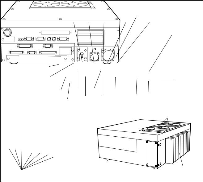
1.2Names of the Robot Controller Components
The following figures show the names of the robot controller components.
n For VM-D/HM-E series |
|
|
|
|
|
|
|
|
|
<Front> |
|
|
|
|
|
|
|
Floppy disk drive (option) |
||
|
CN1 |
CN2 |
CN3 |
CN4 |
|
CN5 |
|
|
|
|
|
|
FG |
|
|
|
|
|
|
terminal |
Robot stop button |
|
|
|
|
|
|
Memory backup |
|
|
|
|
|
|
battery holder |
|
|
|
|
|
|
Pilot lamp |
|
|
|
|
|
CN12 |
|
|
|
|
|
|
|
CN8 |
CN6 |
CN7 |
Fuse box |
|
CN11 |
|
|
|
|
|
Power |
||
|
|
CN9 |
CN10 |
|
||
Output IC box |
|
|
||||
|
|
|
switch |
|
||
<Left side> |
|
|
|
|
<Right side> |
|
|
|
|
|
|
|
Filters (exhaust) |
Filters (air intake) |
|
|
|
|
|
Radiating fin |
|
|
|
|
|
|
|
Names of Robot Controller Components (VM-D/HM-E series)
4
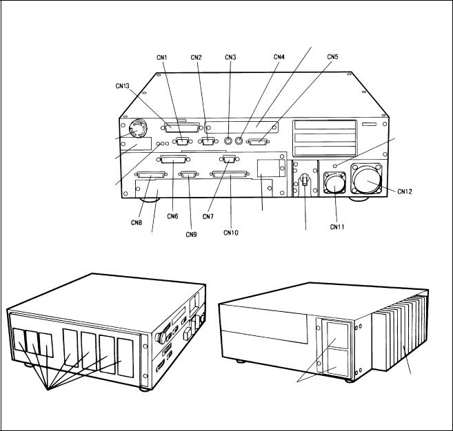
n For robot series except VM-D/HM-E
Robot stop button
Memory backup battery holder
Pilot lamp
Output IC box
<Left side>
Filters (air intake)
<Front>
Floppy disk drive (option)
FG terminal
Fuse box
Power switch
<Right side>
Filters (exhaust) |
Radiating fin |
|
Note: CN13 is not provided on the VS-E and HS-E series.
Names of Robot Controller Components (Robot series except VM-D/HM-E)
5

Connectors for the VM-D, VS-E, and H -E series (Encoders connected via bus)
Connector |
Marking |
Name |
Connector |
Marking |
Name |
No. |
|
|
No. |
|
|
|
|
|
|
|
|
CN1 |
RS232C |
Serial interface |
CN7 |
I/O |
Power connector for |
|
|
connector |
|
POWER |
I/O |
|
|
|
|
|
|
CN2 |
CRT |
CRT connector |
CN8 |
INPUT |
Connector for user input |
|
|
|
|
|
or system input |
CN3 |
KEYBD |
Keyboard connector |
CN9 |
HAND I/O |
Connector for end- |
|
|
|
|
|
effector I/O |
CN4 |
MOUSE |
Connector for PS/2 |
CN10 |
OUTPUT |
Connector for user output |
|
|
mouse |
|
|
or system output |
CN5 |
PENDANT |
Connector for teach |
CN11 |
INPUT AC |
Power connector |
|
|
pendant |
|
|
|
CN6 |
PRINTER |
Printer connector |
CN12 |
MOTOR |
Connector for |
|
|
(Not used.) |
|
|
motor/encoder |
Connectors for the VS-D, VC-E, H -D and XYC-D series (Encoders connected via parallel interface)
Connector |
Marking |
Name |
No. |
|
|
|
|
|
CN1 |
RS232C |
Serial interface |
|
|
connector |
CN2 |
CRT |
CRT connector |
|
|
|
CN3 |
KEYBD |
Keyboard connector |
|
|
|
CN4 |
MOUSE |
Connector for PS/2 |
|
|
mouse |
CN5 |
PENDANT |
Connector for teach |
|
|
pendant |
CN6 |
PRINTER |
Printer connector |
|
|
(Not used.) |
CN7 |
I/O |
Power connector for |
|
POWER |
I/O |
|
|
|
Connector |
Marking |
Name |
No. |
|
|
|
|
|
CN8 |
INPUT |
Connector for user input |
|
|
or system input |
CN9 |
HAND I/O |
Connector for end- |
|
|
effector I/O |
CN10 |
OUTPUT |
Connector for user |
|
|
output or system output |
CN11 |
INPUT AC |
Power connector |
|
|
|
CN12 |
MOTOR |
Motor connector |
|
|
|
CN13 |
ENCODER |
Encoder connector |
|
|
|
 Caution: The robot controller connectors are of a screw-lock type or ring-lock type. Lock the connectors securely. If even one of the connectors is not locked, weak contact may result thereby causing an error.
Be sure to turn the robot controller OFF before connecting/ disconnecting the power connector or motor connector. Otherwise, the internal circuits of the robot controller may be damaged.
6

1.3Robot Controller Specifications
[ 1 ] Specifications
The table below lists the robot controller specifications.
Robot Controller Specifications
|
Item |
|
|
|
Specifications |
|
||
|
|
|
|
|
|
|
|
|
Control system |
PTP, CP 3-dimensional linear, 3-dimensional circular |
|
||||||
(NOTE 1) |
|
|||||||
|
|
|
|
|
||||
No. of controllable axes |
H -D/-E, XYC-D: |
Up to four axes simultaneously |
|
|||||
VC-E (5-axis models): Up to five axes simultaneously |
|
|||||||
(NOTE 1) |
|
|||||||
V -D/-E: |
|
Up to six axes simultaneously |
|
|||||
|
|
|
|
|
||||
Drive system |
All axes: Full-digital AC servo |
|
|
|||||
|
|
|
|
|
||||
Memory capacity |
1.25 MB (equivalent to 5000 steps, 13,000 points) |
|
||||||
|
|
|
|
|
||||
Language used |
DENSO robot language (conforming to SLIM) |
|
||||||
|
|
|
|
|
|
|
|
|
No. of teach programs |
255 |
|
|
|
|
|||
loadable to the memory |
|
|
|
|
||||
|
|
|
|
|
||||
Teaching system |
1) Remote teaching 2) Numerical input (MDI) |
|
||||||
|
|
|
|
|
||||
External |
|
Input signal |
20 user open points (PLC 12, hand input 8) + 36 fixed system points |
|
||||
signals |
|
|
|
|
|
|
|
|
|
Output signal |
32 user open points (PLC 24, hand output 8) + 33 fixed system points |
|
|||||
(I/O) |
|
|
||||||
|
|
|
|
|
|
|
||
|
|
|
|
|
|
|
|
|
|
External |
RS-232C: |
1 line |
|
|
|
||
communication |
Ethernet: |
1 line (option) |
|
|
||||
|
|
|
|
|||||
Timer function |
0.02 to 10 sec. (in units of 1/60 sec.) |
|
||||||
|
|
|
|
|
|
|
||
Self-diagnosis |
Overrun, servo error, memory error, input error, etc. |
|
||||||
|
function |
|
||||||
|
|
|
|
|
|
|||
|
|
|
|
|||||
Error display |
Error codes will be displayed on the external I/O or the operating panel (option). |
|||||||
Error messages will be displayed in English on the teach pendant (option). |
||||||||
|
|
|
||||||
|
|
|
|
|
|
|||
|
|
|
All RC5 models: |
|
3-phase, 200 VAC-15% to 230 VAC+10%, 50/60 Hz |
|||
|
|
|
RC5 for VS-D/-E, H -D/-E, XYC-D: Single-phase, 230 VAC-10% to 230 VAC+10%, |
|||||
Power source |
|
|
|
50/60 Hz |
|
|||
|
|
|
RC5 for VC-E: |
|
Single-phase, 200 VAC-10% to 230 VAC+10%, |
|||
|
|
|
|
|
|
50/60 Hz |
|
|
|
|
|
|
|
||||
Power capacity |
VM-D/HM-E: 3.3 kVA |
|
H -D: 2.0 kVA VS-E: 1.9 kVA HS-E: 1.8 kVA |
|||||
(NOTE 1) |
VS-D, XYC-D: 1.5 kVA |
VC-E: 0.6 kVA |
|
|||||
Environmental conditions |
Temperature: 0 to 40° C |
|
|
|||||
(in operation) |
Humidity: 90% RH or less (no condensation allowed) |
|
||||||
Degree of protection |
IP20 |
|
|
|
|
|||
|
|
|
|
|
||||
|
Robot control |
VM-D, VS-E, H -E: |
Standard: 4 m, 6 m High strength: 6 m, 12 m |
(selectable) |
||||
|
cable |
VS-D, H -D, XYC-D: |
3 m, 6 m |
|
(selectable) |
|||
Cables |
VC-E: |
|
4 m, 6 m |
|
(selectable) |
|||
|
|
|
|
|||||
(option) |
I/O cable |
8 m, 15 m |
|
|
|
|
||
|
|
|
|
|
||||
|
|
|
|
|
|
|
||
|
Power cable |
5 m |
|
|
|
|
||
|
|
|
|
|
|
|
||
|
|
|
VM-D: |
|
Approx. 19 kg (excluding attached cables) |
|
||
|
Weight |
VS-D/-E, VC-E, HS-E: Approx. 17 kg (excluding attached cables) |
|
|||||
|
|
|
H -D/E, XYC-D: |
Approx. 16 kg (excluding attached cables) |
|
|||
NOTE 1: For extended-joint support controllers, refer to the manual "SUPPLEMENT Extended-Joints Support" separately issued.
7

 WARNING
DO NOT touch fins. Their hot surfaces may cause severe burns.
DO NOT insert fingers or foreign objects into openings. Doing so may cause bodily injury.
Before opening the controller cover and accessing the inside of the controller for maintenance, be sure to turn off the power switch, disconnect the power cable, and wait 3 minutes or more. This is for protecting you from electric shock.
DO NOT connect or disconnect connectors to/from the controller while the power switch is on. Doing so may cause electric shock or controller failure.
 CAUTION IN INSTALLATION
This controller is not designed to be dust-proof, splashproof, or explosion-proof.
Read operation manuals before installation.
Do not place anything on the controller.
8

[ 2 ] Outer Dimensions
The outer dimensions of the robot controller are shown below.
Outer Dimensions of Robot Controller (for VM-D/HM-E series and extended-joint support)
Outer Dimensions of Robot Controller (for robot series except VM-D/HM-E)
9
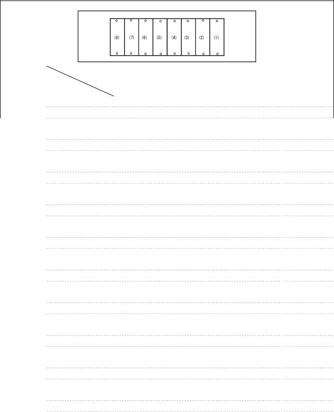
n Location of IPM boards
The table below shows the location of IPM boards for robot series or models.
Rear view of the controller
Series & |
Location |
(8) |
(7) |
(6) |
(5) |
(4) |
|
(3) |
(2) |
|
(1) |
|
|
|
|||||||||
models |
Item |
|
|
||||||||
|
|
|
|
|
|
|
|
|
|
||
|
|
|
|
|
|
|
|
|
|
|
|
|
|
|
|
|
|
|
|
|
|
|
|
VM-6070D |
Joints |
- |
1 |
6 |
5 |
4 |
|
3 |
2 |
|
- |
|
IPM model |
- |
M |
SS |
SS |
SS |
|
S |
L |
|
- |
|
Motor capacity (W) |
- |
750 |
100 |
200 |
200 |
|
400 |
1500 |
|
- |
VM-6083D/ |
Joints |
- |
2 |
6 |
5 |
4 |
|
3 |
1 |
|
- |
VM-60B1D |
IPM model |
- |
M |
SS |
SS |
SS |
|
S |
L |
|
- |
|
|
|
|||||||||
|
Motor capacity (W) |
- |
750 |
100 |
200 |
200 |
|
400 |
1500 |
|
- |
VS-D |
Joints |
- |
- |
6 |
5 |
4 |
|
3 |
2 |
|
1 |
|
IPM model |
- |
- |
SS |
SS |
SS |
|
S |
S |
|
S |
|
Motor capacity (W) |
- |
- |
50 |
50 |
50 |
|
200 |
400 |
|
400 |
VS-E |
Joints |
- |
- |
6 |
5 |
4 |
|
3 |
2 |
|
1 |
|
IPM model |
- |
- |
SS |
SS |
SS |
|
S |
S |
|
M |
|
Motor capacity (W) |
- |
- |
50 |
80 |
100 |
|
200 |
400 |
|
750 |
VC-E |
Joints |
- |
- |
6 |
5 |
4 |
|
3 |
2 |
|
1 |
|
IPM model |
- |
- |
SS |
SS |
SS |
|
SS |
SS |
|
SS |
|
Motor capacity (W) |
- |
- |
30 |
30 |
30 |
|
80 |
80 |
|
80 |
HM/HS-D |
Joints |
- |
- |
- |
- |
4 |
|
3 |
2 |
|
1 |
|
IPM model |
- |
- |
- |
- |
SS |
|
S |
M |
|
M |
|
Motor capacity (W) |
- |
- |
- |
- |
200 |
|
200 |
750 |
|
750 |
HM-E |
Joints |
- |
- |
4 |
3 |
2 |
|
|
1 |
||
|
IPM model |
- |
- |
M |
M |
LL |
|
|
LL |
||
|
Motor capacity (W) |
- |
- |
300 |
300 |
600 |
|
1000 |
|||
HS-E |
Joints |
- |
- |
- |
- |
4 |
|
3 |
2 |
|
1 |
|
IPM model |
- |
- |
- |
- |
S |
|
S |
M |
|
L |
|
Motor capacity (W) |
- |
- |
- |
- |
150 |
|
200 |
400 |
|
750 |
HC-D |
Joints |
- |
- |
- |
- |
4 |
|
3 |
2 |
|
1 |
|
IPM model |
- |
- |
- |
- |
SS |
|
SS |
S |
|
M |
|
Motor capacity (W) |
- |
- |
- |
- |
50 |
|
100 |
400 |
|
750 |
XYC-D |
Joints |
- |
- |
- |
- |
4 |
|
3 |
2 |
|
1 |
|
IPM model |
- |
- |
- |
- |
SS |
|
S |
S |
|
S |
|
Motor capacity (W) |
- |
- |
- |
- |
50 |
|
200 |
400 |
|
200 |
NOTE 1: No IPM board are installed to locations marked with "-." Those locations are covered with blank caps.
NOTE 2: For details about extended-joint support controllers, refer to the manual "SUPPLEMENT Extended-Joints Support."
10
 Loading...