


 Loading...
2D Code Handy Scanner
AT30Q-SM
AT31Q-SM
User's Manual
© DENSO WAVE INCORPORATED, 2016 All rights reserved.
The copyright for this manual is held by DENSO WAVE INCORPORATED.
Any copying or reproduction of this material without prior consent is strictly prohibited.
QR Code, iQR Code, SQRC, and QBdirect are registered trademarks of DENSO WAVE INCORPORATED.
Windows is a registered trademark of Microsoft Corporation in the United States and other countries.
Company names and products are generally the trademark or registered trademark of that company. Specifications are subject to change without notice.

Table of Contents
Table of Contents ....................................................................................................................................................... |
i |
|
Preface........................................................................................................................................................................ |
|
i |
Customer Registration and Inquiries........................................................................................................................... |
i |
|
SAFETY PRECAUTIONS........................................................................................................................................ |
ii |
|
Care and Maintenance .............................................................................................................................................. |
vi |
|
Chapter 1 |
Names and Functions ................................................................................................................................ |
1 |
Chapter 2 |
Preparation ................................................................................................................................................ |
2 |
2.1 |
Operating Environment for the Use of USB Interface ............................................................................... |
2 |
Connecting the Interface Cable to the Scanner................................................................................................ |
3 |
|
Chapter 3 |
Connection to the Host Computer ............................................................................................................. |
3 |
Chapter 3 |
Connection to the Host Computer ............................................................................................................. |
4 |
3.1 |
Using the RS-232C Interface..................................................................................................................... |
4 |
3.2 |
Using the USB Interface............................................................................................................................ |
5 |
|
3.2.1 Setting up the USB-COM interface................................................................................................. |
6 |
|
3.2.2 Setting Up the USB Keyboard Interface.......................................................................................... |
7 |
Chapter 4 |
Scanning Codes......................................................................................................................................... |
8 |
Chapter 5 |
Customizing the Scanner........................................................................................................................... |
9 |
Chapter 6 |
Scanning Control..................................................................................................................................... |
10 |
6.1 |
Trigger Switch Control............................................................................................................................ |
10 |
6.2 |
Software Control ..................................................................................................................................... |
11 |
6.3 |
Reading by Automatic detection of labels ............................................................................................... |
11 |
Chapter 7 |
Scanning Functions ................................................................................................................................. |
12 |
7.1 |
Data verification mode ............................................................................................................................ |
12 |
|
7.1.1 Data verification read procedure ................................................................................................... |
12 |
|
7.1.2 Setting Data Subject to Verification.............................................................................................. |
14 |
|
7.1.3 Verification result output .............................................................................................................. |
15 |
7.2 |
Data Editing ............................................................................................................................................ |
16 |
|
7.2.1 Data Extraction Mode ................................................................................................................... |
16 |
|
7.2.1.1 Data String Extraction ........................................................................................................ |
16 |
|
7.2.1.2 Data Block Extraction......................................................................................................... |
18 |
|
7.2.1.3 Extracting AI (Application Identifier)-prefixed strings....................................................... |
20 |
|
7.2.2 Data Conversion Mode ................................................................................................................. |
28 |
|
7.2.3 Blocksorting mode ........................................................................................................................ |
29 |
|
7.2.4 ADF script mode........................................................................................................................... |
30 |
7.3 |
Point Scan Mode ..................................................................................................................................... |
31 |
7.4 |
Scanning a Mirror Image 2D Code.......................................................................................................... |
31 |
7.5 |
Scanning a Black-and-white Inverted Code............................................................................................. |
31 |
7.6 |
Scanning Structured Appended QR (iQR) Code Symbols....................................................................... |
32 |
7.7 |
Multi-line Barcode Scanning................................................................................................................... |
33 |
|
7.7.1 Number of Lines ........................................................................................................................... |
33 |
|
7.7.2 Data Output Order......................................................................................................................... |
33 |
|
7.7.3 Output Format............................................................................................................................... |
33 |
7.8 |
SQRC Scanning ...................................................................................................................................... |
33 |
Chapter 8 |
Beeper, Indicator LED, Marker, and Illumination LEDs ......................................................................... |
34 |
|
8.1 |
Beeper ..................................................................................................................................................... |
34 |
|
8.2 |
Indicator LED control ............................................................................................................................. |
36 |
|
8.3 |
Marker..................................................................................................................................................... |
38 |
|
|
|
8.3.1 Normal Marker Mode ................................................................................................................... |
38 |
|
|
8.3.2 Marker-OFF mode ........................................................................................................................ |
39 |
|
|
8.3.3 Marker-ON mode.......................................................................................................................... |
39 |
8.4 |
Illumination LEDs................................................................................................................................... |
39 |
|
Chapter 9 |
Communication....................................................................................................................................... |
40 |
|
9.1 |
RS-232C Interface................................................................................................................................... |
40 |
|
9.2 |
USB-COM Interface................................................................................................................................ |
41 |
|
9.3 |
USB Keyboard Interface ......................................................................................................................... |
43 |
|
9.4 |
Communication Format........................................................................................................................... |
44 |
|
9.5 |
GTIN format Conversion ........................................................................................................................ |
56 |
|
Chapter 10 |
Image Capturing.................................................................................................................................... |
61 |
|
10.1 |
Outline of the Function.......................................................................................................................... |
61 |
|
Specifications................................................................................................................................................ |
61 |
||
Chapter 11 |
Parameters and Defaults........................................................................................................................ |
64 |
|
Chapter 12 |
QR-Coded Parameter Menu .................................................................................................................. |
84 |
|
12.1 |
Parameter Setting Procedure Using the QR-coded Parameter Menu...................................................... |
84 |
|
12.2 |
QR-coded Parameter Menu ................................................................................................................... |
85 |
|
Chapter 13 |
Troubleshooting .................................................................................................................................... |
97 |
|
Appendix 1 Specifications....................................................................................................................................... |
98 |
||
Appendix 2 Control Commands .............................................................................................................................. |
99 |
||
Appendix 3 Interface Specifications ...................................................................................................................... |
104 |
||

Preface
Thank you for using the AT30Q / AT31Q DENSO WAVE 2D code Handy Scanner.
Please READ through this manual carefully. It will enable you to operate your scanner correctly. After you have finished reading this manual, keep it handy for speedy reference.
Note: Do not use this scanner in an environment with electrical noise that can trigger malfunction. Note: Specifications described in this manual are supported by AT30Q Firmware version 1.00 or later.
DENSO WAVE INCORPORATED does not assume any product liability arising out of, or in connection with, the application or use of any product, circuit, or application described herein.
If it is judged by DENSO WAVE INCORPORATED that malfunction of the product is due to the product having been dropped or subjected to impact, repairs will be made at a reasonable charge even within the warranty period.
Intellectual Property Precaution
DENSO WAVE INCORPORATED (“DENSO WAVE”) takes reasonable precautions to ensure its products do not infringe upon any patent of other intellectual property rights of other(s), but DENSO WAVE cannot be responsible for any patent or other intellectual property right infringement(s) or violation(s) which arise from (i) the use of DENSO WAVE’s product(s) in connection or in combination with other component(s), product(s), data processing system(s) or equipment or software not supplied from DENSO WAVE; (ii) the use of DENSO WAVE’s products in a manner for which the same were not intended nor designed; or (iii) any modification of DENSO WAVE’s products by other(s) than DENSO WAVE.
Limited Warranty on Software Products
In no event will DENSO WAVE be liable for direct, indirect, special, incidental, or consequential damages (including imaginary profits or damages resulting from interruption of operation or loss of business information) resulting from any defect in the software or its documentation or resulting from inability to apply the software or its documentation.
Customer Registration and Inquiries
Customer Registration
To allow us to provide our customers with comprehensive service and support, we request that all customers complete a Member Registration Form. Registered members will be offered the following privileges.
•Latest upgrade information
•Free exhibition and event information for new products
•Free web-information service “QBdirect”
QBdirect Service Contents
Information search service |
Offers detailed information on each product. |
(FAQ) |
|
|
|
Download service |
Offers downloads of repair modules for the latest AT30Q Series systems or software, |
|
and sample programs. |
E-mail inquiries |
Allows customers to send product-related queries by e-mail. |
|
|
Please note that these privileges may be subject to change without prior notice.
How to Register
Access the URL below and follow the instructions provided. http://www.qbdirect.net
i
SAFETY PRECAUTIONS
Be sure to observe all these safety precautions.
Please READ through these instructions carefully. They will enable you to use the scanner correctly.
Always keep this manual nearby for speedy reference.
Strict observance of these warnings and cautions is a MUST for preventing accidents that could result in bodily injury and substantial property damage. Make sure you fully understand all definitions of these terms and symbols given below before you proceed to the text itself.
Alerts you to those conditions that could cause serious bodily injury or death if the instructions are not followed correctly.
WARNING
CAUTION Alerts you to those conditions that could cause minor bodily injury or substantial property damage if the instructions are not followed correctly.
Meaning of Symbols
A triangle ( ) with a picture inside alerts you to a warning of danger. Here you see the warning for electrical shock.
A diagonal line through a circle ( ) warns you of something you should not do; it may or may not have a picture inside. Here you see a screwdriver inside the circle, meaning that you should not disassemble.
A black circle ( ) with a picture inside alerts you to something you MUST do. This example shows that you MUST unplug the power cord.
ii

 WARNING
To System Designers:
•When introducing the scanner in those systems that could affect human lives (e.g., medicines management system), develop applications carefully through redundancy and safety design which avoids the feasibility of affecting human lives even if a data error occurs.
•Never bring any metals into contact with the terminals in connectors.
Doing so could produce a large current through the scanner, resulting in heat or fire, as well as damage to the scanner.
•Keep the AC adapter away from water.
Failure to do so could cause fire or electrical shock.
•Never use the scanner on the line voltage other than the specified level.
Doing so could cause the scanner to break or burn.
•Do not use the scanner where any inflammable gases may be emitted.
Doing so could cause fire.
•Do not scratch, modify, bend, twist, pull, or heat the power cable of the AC adapter. Do not place heavy material on the cable or allow the cable to get pressed under heavy material.
Doing so could break the cable, resulting in a fire.
•If smoke, abnormal odors or noises come from the scanner, immediately switch off the host computer, disconnect the AC adapter and the interface cable, and contact your nearest dealer. Failure to do so could cause fire or electrical shock.
•If foreign material or water gets into the scanner, immediately unplug the AC adapter and the interface cable, and contact your nearest dealer.
Failure to do so could cause fire or electrical shock.
•If you drop the scanner so as to affect the operation or damage its housing, switch off the host computer, unplug the AC adapter and the interface cable, and contact your nearest dealer. Failure to do so could cause fire or electrical shock.
iii

 CAUTION
• Never disassemble or modify the scanner; doing so could result in an accident such as break or fire.
Doing so could result in a fire or electrical shock.
Never disassemble
•Do not put the scanner on an unstable or inclined plane.
The scanner may drop, creating injuries.
•Never put the scanner in places where there are excessively high temperatures, such as inside closed-up automobiles, or in places exposed to direct sunlight.
Doing so could affect the housing or parts, resulting in a fire.
•Avoid using the scanner in extremely humid areas, or where there are drastic temperature changes.
Moisture will get into the scanner, resulting in malfunction, fire or electrical shock.
•Do not place the scanner anyplace where it may be subjected to oily smoke or steam, e.g., near a cooking range or humidifier.
Doing so could result in a fire or electrical shock.
•Never cover or wrap up the scanner or AC adapter in a cloth or blanket.
Doing so could cause the unit to heat up inside, deforming its housing, resulting in a fire. Always use the scanner and AC adapter in a well-ventilated area.
•Keep the power cable of the AC adapter away from any heating equipment.
Failure to do so could melt the sheathing, resulting in a fire or electrical shock.
•Do not scratch or modify the scanner or its interface cable. Do not bend, twist, pull, or heat the cable.
Doing so could damage the scanner or its interface cable, creating a fire hazard.
•Do not put heavy material on the scanner or its interface cable, or allow the cable to get pressed under heavy material.
•Do not look into the light source from the scanning window or do not point the scanning window at other people's eyes.
Eyesight may be damaged by direct exposure to this light.
•Do not use the scanner if your hands are wet or damp.
Doing so could result in an electrical shock.
•Never use chemicals or organic solvents such as naphtha and thinner to clean the housing. Do not apply insecticide to the scanner.
Doing so could result in a marred or cracked housing, electrical shock or fire.
•Do not use the scanner with anti-slip gloves containing plasticizer.
The scanner housing may be broken, creating injuries, electrical shock, or fire.
•Do not use or store the scanner in the place where strong magnetism or static electricity are likely produced near the processing machine or on the carpet.
Doing so could affect the parts, resulting in malfunction or failure.
iv

 CAUTION
•When disconnecting the AC adapter from the wall socket, hold the AC adapter body not the power cable.
The power cable may be broken, resulting in a burnt AC adapter, electrical shock, or fire.
•If the interface cable is damaged (e.g., exposed or broken lead wires), stop using it and contact your nearest dealer.
Failure to do so could result in a fire or electrical shock.
•During electrical storm activity, always unplug the AC adapter from the wall socket.
Exposure to power surges could result in a damaged scanner or fire.
•When taking care of the scanner, unplug the AC adapter from the wall socket for safety.
Failure to do so could result in an electrical shock.
•Do not drop the scanner.
The scanner housing may be broken, creating injuries.
Using the scanner whose housing is broken could result in smoke or fire. Unplug the AC adapter from the wall socket and contact your nearest dealer.
v

Care and Maintenance
■ Proper Care of the reading window
Dust or dirt accumulating on the clear plate of the code reading window will affect reading performance. If you use the scanner in dusty areas, therefore, periodically check the clear plate and clean it if dusty.
•To clean the plate, first blow the dust away with an airbrush. Then wipe the plate with a cotton swab or the similar soft one gently.
•If sand or hard particles have accumulated, never rub the plate; doing so will scratch or damage it. Blow the particles away with an airbrush or a soft brush.
■ Proper Care of the Scanner body
Wipe any dirt from the Scanner body with a dry, soft cloth.
Note
•Never use substances such as naphtha or alcohol, as this may cause the housing to be marred or paint to peel off.
•If excessively dirty, wipe a soft cloth that has been soaked in soapy water (always use neutral detergent) and wrung out thoroughly.
vi
Chapter 1 Names and Functions
Reading window
A code is placed at this reading window.
Trigger switch
Press this switch to start code reading. The following trigger switch operating modes are available.
Auto off mode
Momentary switching mode
Momentary switching mode
(Reverse Type)
Alternate switching mode
Continuous reading mode 1
Continuous reading mode 2
Auto sense mode
Auto stand mode
(The factory default setting is Auto-off mode .)
(Refer to Chapter 6 for |
|
details.) |
Bottom case |
|
|
|
Interface cable |
Indicator LED control
Illuminates blue when reading is complete.
(Refer to Section 8.2 for details.)
Beep hole
The beeper sounds when the scanner has read a code successfully.
Case
AT30Q Light gray
AT31Q Black
 Connector cover
Connect the interface cable to a PC, etc. There are the following two types of interface cables available.
RS-232C Interface
USB Interface
The interface cable connects your scanner to a host computer or other host equipment.
Depending upon the interface cable plugged into the scanner, the scanner automatically switches to the RS-232C interface or USB-COM interface.
 (Refer to Chapter 3 for the cable connection and setting up of the USB interface.)
Note: The bottom case is not securely held in the scanner case when the interface cable and its connector case cover are not plugged into the case. If the bottom case comes off, fit it firmly in the scanner case again, and connect the interface cable and then the connector cover over it.
1
Chapter 2 Preparation
2.1 Operating Environment for the Use of USB Interface
Using the scanner via the USB interface requires a host computer equipped with a USB port. The operating environment differs depending upon whether you use the USB-COM interface or USB keyboard interface as listed below. (Plugging the USB interface cable in the scanner automatically switches to the USB-COM interface by default.)
USB-COM interface: |
To use this interface, you need to install the dedicated Active USB-COM port driver (virtual |
|
(Default Setting) |
COM port driver) to the host computer. This interface allows you to use the scanner in |
|
|
applications using the conventional serial port. For instructions on how to set up the driver, refer |
|
|
to Section 3.2.1. For the interface specifications, refer to Section 9.2. |
|
USB keyboard interface: |
No dedicated USB device driver is required. Via this interface, data scanned by the scanner can |
|
|
be entered to the cursor position in your application. For instructions on how to set up the driver, |
|
|
refer to Section 3.2.2. For the interface specifications, refer to Section 9.3. |
|
|
|
|
|
To use the USB-COM interface (factory |
To use the USB keyboard interface: |
|
default): |
|
|
|
|
Host computer |
Windows machine |
|
|
|
|
USB driver |
Active USB-COM port driver provided by |
OS-supplied device driver |
|
DENSO WAVE |
|
Note: For the compatible operating systems, see QBdirect.
The interface can be switched between the USB-COM interface and USB keyboard interface by using either the:
-Using QR-coded parameter menu (provided in Chapter 12),
-Using the configuration software (ScannerSetting_2D)*
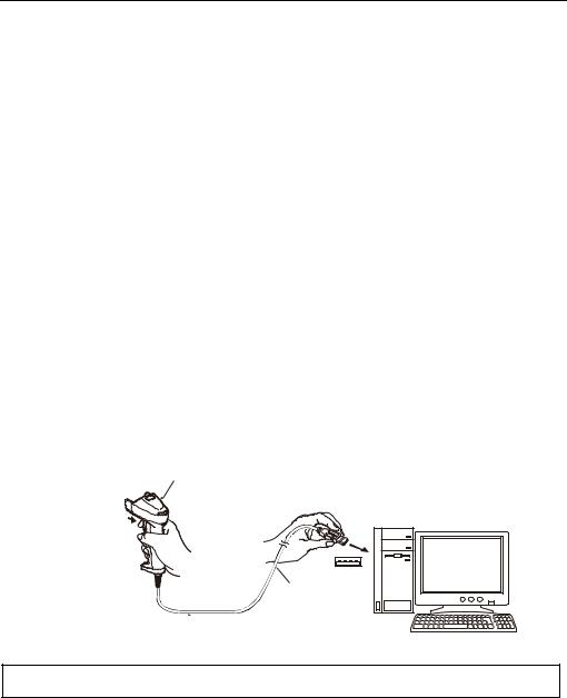
If the Active USB-COM port driver is not installed in the computer, (1) connect the scanner’s USB interface cable to the computer or its USB hub, and (2) press the trigger switch for more than two seconds.
However, this applies only when the USB-COM interface is set up, in which case the interface can be switched from the USB-COM interface to the USB keyboard interface. Switching the interface vice versa is not supported.
(2) Press the trigger switch key for two seconds or more.
Scanner
(1) Connect the USB interface cable.
USB interface cable
The interface setting will be retained even if the scanner is turned off.
Note: For approx. 20 seconds after switching from the USB-COM interface to the USB keyboard interface, the scanner cannot accept data entry.
*Registered users can download the configuration software (ScannerSetting_2D) from QBNet, their customer support section on the Denso Wave website at no extra charge.
http://www.qbdirect.net
2

2.2.Connecting the Interface Cable to the Scanner
(1)Pull the connector cover of the interface cable off its connector as shown below.
(2)Plug the interface cable connector into the connector located in the bottom of the scanner.
Note: Note: As shown below, hold the scanner body, align the ▼ mark on the cable connector with that on the scanner, and fully insert the interface cable connector.
Scanner
Scanner
▼ mark
Connector
▼ mark
Connector cover
(3)Align the ▼ mark on the scanner with that on the connector cover, and fully insert the connector cover to the scanner until the grommet line is shown. Then, turn it clockwise until the boss on the connector cover becomes horizontal against the scanner.
Cutout |
▼ mark |
Grommet line
Boss |
Connector cover |
▼ mark |
|
Connector cover
 Turn the cover until its bosses comes to be horizontal.
3

Chapter 3 Connection to the Host Computer
3.1 Using the RS-232C Interface
(1) AC adaptor-powered type
(a) Connect the RS-232C interface cable to the host computer.
Scanner
AC adapter
 DC jack
RS-232C interface cable |
Serial port |
|
(b) Plug the AC adapter into the DC power jack provided in the RS-232C interface cable connector.
Note: When disconnecting the interface cable or DC power jack, hold the connector housings not the cables. Pulling cables will result in breaks.
Note: Note: Avoid connecting and disconnecting of connectors all if possible. Doing so may result in weak contact. Note: Be sure to use the adapter exclusively designed for the scanner.
(2)Host computer-powered type
(a)Connect the interface cable to the host computer. *
(b)Secure the connector if it is equipped with a lock.
*Refer to the specifications for details of the interface cable connector types, pin assignments and lock facility.
Note
When disconnecting the interface cable or DC power jack, hold the connector housings not the cables. Pulling cables will result in breaks.
Avoid connecting and disconnecting of connectors all if possible. Doing so may result in weak contact.
4

3.2 Using the USB Interface
The scanner receives and sends data from/to the host computer through the USB-COM interface or USB keyboard interface. You need to set up the device driver designed for the interface to be used (see 3.2.1 and 3.2.2).
Notes for connecting the USB interface cable
To use the USB-COM interface, you need to install the serial port driver to the host computer before connection of the USB interface cable.
Scanner
USB port
USB interface cable
When plugging and unplugging the USB connector, put an interval of at least 10 seconds between those actions since Windows may take several to 10 seconds to add or delete the USB device.
Hot plugging/unplugging is allowed for USB devices. However, do not plug or unplug the USB connector when:
-The computer is on standby (in Suspend mode) or
When the host computer is processing the scanner connection, do not plug or unplug any other USB device cables.
Directly connect the scanner to the USB port on the host computer or to the self-powered hub. The scanner may not be connected to some types of hubs. If the operation of the hub-connected scanner is unstable, connect it directly to any USB port on the host computer.
Do not use any extension cord.
5

3.2.1 Setting up the USB-COM interface
Using the USB-COM interface requires installing the Active USB-COM port driver provided by DENSO WAVE to the host computer. The driver does not come with the scanner in a CD-ROM. It can be downloaded for free from our website at:
http://www.qbdirect.net
The file downloaded contains the Active USB-COM port driver and uninstaller which are compressed. It is a self-extracting file. Store the file into a folder and then double-click its icon to extract it.
For the latest information, refer to the manual that comes with the driver.
Notes for installing and using the Active USB-COM port driver
The driver should be installed with administrative permission (Administrator Login).
The driver does not contain a Microsoft digital signature. Therefore, do not block installation of drivers containing no signature with the driver’s signature option or local policy’s security option.
The driver allows hot plugging or unplugging of a USB device even during communication (when the COM port is being opened); however, the communications data when the USB device is disconnected will be lost.
The driver always serves as a virtual serial port even if a USB device is unplugged, so the driver always occupies a COM port number.
The driver cannot coexist with conventional Denso USB-COM device drivers in a host computer. In the installation procedure, the Active USB-COM port driver requires uninstalling the conventional ones.
Installing the driver on a single host computer more than one time enables more than one USB device to be used. However, the uninstaller of the Active USB-COM port driver uninstalls previously installed drivers, not individually but all at once.
Installation procedure
Refer to the installation procedure for “Active USB-COM Port Driver Installation Guide.”
6
3.2.2 Setting Up the USB Keyboard Interface
A USB class driver “HID (Human Interface Devices)” is used to communicate using the USB keyboard interface. This driver is included in the Windows system files.
Note: If the scanner is set to the USB-COM interface, follow the procedures in Section 2.1 to switch to the USB keyboard interface. (Factory settings: Set to USB-COM interface)
Connect the scanner USB interface cable to the USB port of the computer itself or USB hub.
For the following we will explain using examples from Windows 7, Windows 8, and Windows Vista procedures.
Windows 7, Windows 8, Windows Vista
(1)Turn on the computer and activate Windows 7, Windows 8 or Windows Vista, and log in as a user with administrator privileges.
(2)Connect the USB interface cable of the scanner to the computer or USB hub.
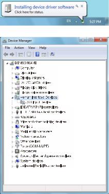
(3)The message, “Installing device driver software” is displayed on the taskbar at the lower right of the screen.
Scanner recognition will be automatic. Once the scanner has been recognized the message will disappear.
(4)To check whether the USB device has been installed correctly, go to the “Device Manager” screen.
If “USB input device” has been added under the “Human Interface Devices” menu item, the scanner has been connected correctly.
Reconnect the scanner if this item has not been added, or if a
 or
or  mark is displayed.
7

Chapter 4 Scanning Codes
(1)Bring the reading window to the target code and press the trigger switch. The marker indicating the approximate center of the reading area irradiated by the illumination LEDs lights up for reading.
(This step is not required for the Continuous reading modes 1, 2, Auto sensing mode and Auto stand mode.)
Marker
Working distance
Illumination LEDs
Indicator
 LED control
Trigger switch
(2) Wait for the indicator LED to turn blue and the beeper to sound, indicating a successfully read.
Note: The reading area is narrower than the irradiation area of the illumination light.
When the scanning distance is 9 cm, the reading area is approx. 9 x 6 cm.
Note: Note: Allow only a single code to come within the field of view except when the multi-line code scanning is allowed. Having more than one code within the field of view either causes the read to fail or produces multiple input.
Note: Note: The double-read prevention enabled time can be specified with the configuration software (ScannerSetting_2D).
Note: The scanner can read codes omnidirectionally. Note that a target code plus its margin should lie within the reading area.
Note: If the scanner fails to read due to specular effects or other factors, change the scanning angle of the reading window or the distance from the codes, and repeat the process. (Specular effects occur when the reflection of the light from the label surface is too strong, such as when the reflecting surface is polished or covered with vinyl.)
Scanning mode
Normal scanning mode |
This mode transfers the code data when the scanner has read the code successfully. |
|
|
Data verification mode |
This mode verifies the code data against the master data stored in the scanner. |
|
(Refer to Section 7.1 for details.) |
|
|
|
8 |

Chapter 5 Customizing the Scanner
You can customize the scanner by modifying communications, code type, and other scanner parameters with the QR-coded parameter menu or the configuration software ScannerSetting_2D*. These parameters retain their settings even when the power is off.
(1)Scanning parameter setting QR Codes from the QR-coded parameter menu by pressing the trigger switch. (The QR-coded parameter menu is given in Chapter 12.)
(2)Using the configuration software (ScannerSetting_2D)* in your computer.
The configuration software is available via the RS-232C interface or USB-COM interface; it is not via the USB keyboard interface. If the USB keyboard interface is set, the interface needs to be changed to the USB-COM interface. (In this case, there is a need to change the interface to the USB-COM interface using the QR code menu and install the Active USB-COM port driver provided by us. See Section 3.2.1.)
(The configuration software also offers batch-process QR code symbols for read by scanners in the field. Those symbols printed can be scanned by the scanner via any of the RS-232C interface, USB-COM interface and USB keyboard interface.
Note: The configuration software is not available via the USB keyboard interface.
*Registered users can download the configuration software (ScannerSetting_2D) from QBNet, their customer support section on the Denso Wave website at no extra charge.
http://www.qbdirect.net
9

Chapter 6 Scanning Control
Two types of scanning controls are available--Trigger switch control and Software control. Trigger switch control: Pressing the trigger switch readies the scanner for reading. (Refer to Section 6.1.)
Software control: Instead of pressing the trigger switch, you send control commands from the host computer via the RS-232C or USB-COM interface to ready the scanner for reading or put the scanner on standby. (Refer to Section 6.2.)
In addition, the auto sensing mode and auto stand mode are also available. (Refer to Sections 6.3)
6.1 Trigger Switch Control
Pressing the trigger switch turns on the illumination LEDs and readies the scanner for reading. The scanner supports the following six trigger switch operating modes. Select the one that best meets your needs using the QR-coded parameter menu or the configuration software (ScannerSetting_2D).
(1) Auto off mode
When the trigger switch is pressed, the scanner is brought to the Active state for approximately 5 seconds.
The scanner automatically returns to the Ready state when reading is successfully completed, or after approximately five seconds elapsed with the trigger switch pressed.
The scanner goes to the Ready state if the trigger switch is released before five seconds elapses.(in the case of normal mode) When One Shot is set to the Auto off mode, you can set the duration of the Active state after the trigger switch is pressed.
(2) Momentary switching mode
The scanner is brought to the Active state only when the trigger switch is pressed, and returns to the Ready state when the trigger switch is released.
(3) Momentary switching mode (Reverse type)
The scanner is brought to the Ready state only when the trigger switch is pressed, and returns to the Active state when the trigger switch is released.
(4) Alternate switching mode
The scanner alternates between the Active state and the Ready state every time the trigger switch is pressed.
(5) Continuous reading mode 1
When you turn the scanner on, the scanner lights the illumination LEDs and becomes ready to scan. The scanner ignores all trigger switch input. If the scanner receives the Z, READOFF or LOFF command, it switches to standby; if it receives the R, READON or LON command, it becomes ready to scan.
You can select whether or not the scanner transmits the ERROR command when the scanner cannot complete reading and switches to standby, using the configuration software (ScannerSetting_2D).
(6) Continuous reading mode 2
This mode is functionally equivalent to the Continuous Reading mode 1, except that the scanner waits for a command upon completion of reading. To become ready to scan, the scanner should receive the Z, READOFF or LOFF command to switch to standby and then receive the R, READON or LON command.
You can select whether or not the scanner transmits the ERROR command when the scanner cannot complete reading and switches to standby, using the configuration software (ScannerSetting_2D).
Note: When you are setting parameters using the QR-coded parameter menu, the scanner is always in the Auto-off mode regardless of the trigger switch operating mode selected.
10
6.2 Software Control
You can control the scanner by sending scanning control commands from the host computer via the RS-232C or USB-COM interface, instead of pressing the trigger switch.
Reading control commands are restricted by the trigger switch operating modes, as listed below. (For more information on control commands, see Appendix 2 Control Commands.)
|
|
|
Trigger switch operating modes |
|
|||
|
|
|
|
|
|
|
|
Commands |
Description |
Auto off mode |
Momentary switching mode (Reverse type) |
Momentary switching mode |
Alternate switching mode |
Continuous reading mode 1 |
Continuous reading mode 2 |
|
|
||||||
|
|
|
|
|
|
|
|
|
Ready-to-scan commands |
× |
× |
× |
× |
○ |
○ |
R, READON, LON |
Upon receipt of one of these commands, the scanner |
||||||
|
lights the illumination LEDs and becomes ready to scan. |
|
|
|
|
|
|
|
|
|
|
|
|
|
|
|
Standby commands |
× |
|
|
|
|
|
Z, READOFF, LOFF |
Upon receipt of one of these commands, the scanner |
× |
× |
× |
○ |
○ |
|
|
turns off the illumination LEDs and switches to standby. |
|
|
|
|
|
|
|
|
|
|
|
|
|
|
Each of these commands should be enclosed with a header and terminator for transmission according to the communications conditions of the scanner.
6.3 Reading by Automatic detection of labels
In auto Sensing mode (Auto sense operation in Auto stand mode is included), bringing a code label within the reading area of the reading window turns on the illumination LEDs and starts the scanner reading the code. Use this mode when the scanner is stationary to a stand and a code label is moved.
The illumination LEDs come on when you bring a code label within the designated range or move a code label within the same range. These LEDs go off when a code label is moved away from the range or stays within the range without move for approx. 3 seconds.
In the Auto stand mode, the scanner is set to the Auto sense mode when the power is turned on.
If the trigger switch is pressed while the scanner is operating in this mode, the scanner goes to the Auto off and reads a barcode whenever the trigger switch is pressed. However, the scanner will automatically return to the Auto sense mode if the trigger switch is not pressed for longer than a time specified for the scanner to return to the Auto sense mode. If the trigger switch is pressed three times in about one second while the scanner is operating in Auto off mode, you can manually return the scanner to the Auto sensing mode.
The method and time for the scanner to return to the Auto sensing mode from the Auto off mode can be selected with the setting software (ScannerSetting_2D).
Auto sensing mode and Auto stand mode are selected with the QR-coded parameter menu or the configuration software (Scanner Setting_2D). The scanner offers a choice of three sensitivity levels for responding to codes. Switch to a higher sensitivity level if the illumination LEDs will not come on when a code is brought into the range, for example. The sensitivity level can be selected with the configuration software (ScannerSetting_2D).
Note: Even if you do not bring a code label within the reading area, the illumination LEDs may come on when the ambient level of light changes or any shadows move within the reading area.
Note: To enable the scanner to work properly in the Auto sensing mode, an ambient illuminance of at least 500 lx is required.
11

Chapter 7 Scanning Functions
7.1 Data verification mode
The Data verification mode verifies the code data read against the master data stored in the scanner and reports the match status with data output.
Data verification read is available in two types--“n-point verification” and “2-point verification,” which can be selected with the configuration software (ScannerSetting_2D).
Selecting the n-point verification requires registering master data only one time for 1:n verification. The scanner verifies all code data read after registration against the master data.
The 2-point verification refers to 1:1 verification. Selecting it requires registering master data each time preceding code scanning. This way, the 2-point verification read alternately repeats master data registration and code scanning.
In n-point verification read, master data can be registered with “preset master registration” or “scan master registration”; in 2-point verification read, with “scan master registration” only. The preset master registration registers master data with the configuration software (ScannerSetting_2D) beforehand. The scan master registration registers master data by scanning a master code label.
The master data registered by either method will be sent to the host computer when you scan the “Output master data” code given on page 23.
The verification parameters can be specified with the configuration software (ScannerSetting_2D).
7.1.1 Data verification read procedure
n-point Verification
Preset master registration
This is available only when n-point verification is selected. Register the code type and data to be used for verification using the configuration software (ScannerSetting_2D). Up to 99 digits can be registered.
The registered master data will be preserved even if the scanner is turned off. To clear it, first clear the registered master data stored in the host computer with the configuration software (ScannerSetting_2D) and then send the new setting data to the scanner.
Scan master registration
1)Switch the scanner to the Data Verification mode and select the RS-232C or USB-COM interface.
2)Send a scan entry control command “E” from the host to the scanner. (Refer to Appendix 2 for control commands.) The indicator LED lights in green.
3)Use the scanner to scan a master code to be registered. (The scanner operates in the trigger switch operating mode currently set.) After registration of master data, the indicator LED turns blue and then goes OFF.
4)Use the scanner to scan a target code. The scanner verifies the code read against the master data registered and then outputs the result. After a successful read, the indicator LED lights in blue.
During the registration operation above, if the master data has fewer characters than specified (e.g., less than the specified verification start position), the registration operation aborts with an error.
Even if “Preset master registration” has been made, you can make “Scan master registration.” If both have been made, the number of characters to verify that has been specified with “Preset master registration” and the master data that has been specified with “Scan master registration” will be valid.
Note: The registered master data will be cleared when you customize the scanner by modifying the parameters with the configuration software (ScannerSetting_2D) or a batch-process QR code symbol.
Note: If no master data has been entered by either “Preset master registration” or “Scan master registration,” the indicator LED flashes in red, during which it is impossible to scan codes. During blinking, codes cannot be scanned.
Note: When the USB keyborad interface is used in the n-point Verification mode, the n-point Verification is disabled and the normal reading mode is automatically selected if preset registered data is not present.
12

2-point Verification
Scan master registration
1)Switch the scanner to the Data Verification mode and select the RS-232C or USB-COM interface. The indicator LED lights in green.
2)Use the scanner to scan a master code to be registered. (The scanner operates in the trigger switch operating mode currently set.) After registration of master data, the indicator LED turns blue and then goes OFF.
3)Use the scanner to scan a target code. The scanner verifies the code read against the master data registered and then outputs the result.
After a successful read, the indicator LED lights in blue and then turns green, indicating that the scanner is ready to register new master data.
During the registration operation above, if the master data has fewer characters than specified (e.g., less than the specified verification start position), the registration operation aborts with an error. The scanner becomes ready to register master data again.
*Verification retry after mismatch in 2-point verification
The 2-point verification read provides the “Verification retry after mismatch” option that retries verification against the same master data. Enabling this option with the configuration software (ScannerSetting_2D) readies the scanner not for registering new master data but for reading a bar code again if the verification result is a mismatch. Disabling this option readies the scanner for registering new master data after bar code reading, no matter what the verification result is.
Note: Any of the following events clears the master data stored in the scanner.
Turning the scanner power off.
Modifying the verification start position or the number of characters to verify.
Customizing the scanner by modifying the parameters with the configuration software (ScannerSetting_2D) or by scanning a batch-process OR code symbol.
Note: The Data verification area can be selected from “Code type + code data” or “Code data only” with the configuration software (ScannerSetting_2D).
13

7.1.2 Setting Data Subject to Verification
You can specify two types of verification objects--data string and data block. For data string verification, specify the verification start position and the number of characters to be verified. For data block verification, specify one of the data blocks delimited by commas in the CSV format.
(1) Data String Verification
The scanner verifies data specified by the verification start position and the number of characters to be verified against the master data registered in the scanner, and then it outputs the verification result.
The verification start position should be within the range of 1 to 999, and the number of characters to be verified should be within the range of 1 to 99*.
(*The number of characters for Code 39 and Codabar (NW-7) symbols should be specified including start and stop codes. ) In any of the following cases, the verification results in a mismatch:
1)The data in the specified range does not match.
2)The code type which the verification data belongs to is different from the one which the master data belongs to. See (Note) below.
3)All data specified is not included or no data is included within the specified range.
(Examples)
Master data |
Verification |
Number of digits to |
Data string read |
Result |
registered |
star position |
be verified |
(Verification object) |
|
345 |
3 |
3 |
00345 |
Match |
345 |
3 |
3 |
00345678 |
Match |
345 |
3 |
3 |
00346 |
Mismatch |
345 |
3 |
3 |
0034 |
Mismatch |
(2) Data Block Verification
If data is saved in the comma-delimited CSV format, the scanner verifies data in the specified data block against the master data registered in the scanner, and then outputs the verification result.
The data block position should be within the range of 1 to 99.
In any of the following cases, the verification results in a mismatch:
1)Data of specified block is different.
2)The code type which the verification data belongs to is different from the one which the master data belongs to. See (Note) below.
3)All data specified is not included or no data is included within the specified block.
4)Number of digits for block to be verified exceeds 99.
(Examples)
Master data |
Verification block |
Data string read |
Result |
|
registered |
position |
(Verification object) |
||
|
||||
345 |
3 |
0,12,345,6789 |
Match |
|
345 |
3 |
0,12,346,6789 |
Mismatch |
|
345 |
3 |
0,12,3456,6789 |
Mismatch |
|
345 |
3 |
0,12,34,6789 |
Mismatch |
|
345 |
3 |
0,12 |
Mismatch |
Note: Whether the code ID mark is matched is determined not by the combination of code ID marks specified in the configuration software (ScannerSetting_2D) but by Type 1 only. (Refer to Section 9.4.)
14

7.1.3 Verification result output
(1) Report of match/mismatch status
You can select any of the following report types using the configuration software (ScannerSetting_2D). Selecting “Disable transmission” reports nothing.
|
If there is a match: |
If there is a mismatch: |
|
|
|
1 |
Disabled |
Disabled |
|
|
|
2 |
Enable code data transmission. |
Enable code data transmission. |
|
|
|
3 |
Enable OK transmission. |
Enable NG transmission. |
|
|
|
(2) Beeper and indicator LED
You can check whether the verification result is a match or mismatch with the beeper and indicator LED. When the beeper and indicator LED are enabled, they act as shown below.
|
BEEPER |
Indicator LED |
|
|
control |
||
|
|
||
|
|
|
|
If there is a match: |
Emits a short |
Lights in blue. |
|
beep. |
|||
|
|
||
|
|
|
|
If there is a mismatch: |
Emits a long |
Lights in red. |
|
beep. |
|||
|
|
||
|
|
|
Output of the master data registered
Scanning the “Output master data” code given below lets the scanner output the verification section of master data entered in the Data verification read procedure, together with the code ID mark.
“Output master data” code
15
7.2 Data Editing
You can edit and output code data read, in any of the four data edit modes--“data extraction mode,” “data substitution mode,” “data blocksorting mode” and “ADF script mode.” These data edit modes can be selected with the configuration software (ScannerSetting_2D). The default is “No editing.”
(Note 1) Note: In the case of multi-line bar codes, unless all code ID marks read are matched, the data editing processing will result in an error regardless of whether or not the data read contains any error. Whether the code ID mark is matched is determined not by the combination of code ID marks but by Type 1 only. (Refer to Section 9.4.)
(Note 2) In the case of Structured Appended QR (iQR) Code, the scanner in edit mode or batch edit mode performs data editing processing upon completion of scanning of all split Code symbols; In non-edit mode, it performs each time a single split Code symbol is read.
7.2.1 Data Extraction Mode
This mode extracts and outputs part of the scanned data. This mode offers three extraction choices--“data string extraction,” “data block extraction” and “AI (Application Identifier)-prefixed string extraction”. The “data block extraction” is available only when code data is in the comma-delimited CSV format. The “AI-prefixed string extraction” is available for GS1-128 , GS1 DataBar, and GS1 Composite (excluding linear components in GS1 Composite).
7.2.1.1 Data String Extraction
The scanner extracts a data string specified by the “Extraction start position” and “Extraction end position” from a code specified by the “Code type” and then outputs it in the data transmission format selected in the scanner (see Section 9.4). The extraction conditions and extraction start and end positions are listed below.
Setting options
Item |
Options |
Code type |
Any code |
|
QR Code |
|
iQR Code |
|
PDF417 |
|
Data Matrix |
|
MaxiCode |
|
Aztec |
|
UPC-A/EAN-13 |
|
UPC-E |
|
EAN-8 |
|
Code 128 |
|
GS1-128 |
|
Codabar (NW-7) |
|
Code 39 |
|
Code 93 |
|
Interleaved 2of5(ITF) |
|
Standard 2of5(STF) |
|
GS1 DataBar |
|
GS1 Composite |
“Data transfer regardless of error result” |
Enabled/Disabled |
If the scanner fails to extract a data string or scans a code not specified by “Code type” when the “Data transfer regardless of error result” is permitted, then it outputs the data read as is without editing.
16

Extraction start and end positions
Start Position |
End Position |
First character |
nth position |
Last character |
|
nth position |
Last character |
|
By n positions from the start |
|
position |
|
nth position |
The n can be 1 through 9999. Note that if the extraction start position is specified as nth position, the extraction end position should be equal to or greater than the extraction start position.
Note: The number of characters for Code 39 and Codabar (NW-7) symbols should be specified including start and stop codes.
Example: Code read: QR Code, Data: 12345,
Header: STX; Terminator: ETX; Scanner ID: Prohibited; Code mark: Type 1; Number of digits: Permitted; Prefix/Suffix : Not specified; BCC: Prohibited
Setting options |
Start Position |
End Position |
Transmitted Data |
|
“Code type”: QR Code |
First character |
3rd position |
[STX]Q0003123[ETX] |
|
“Data transfer |
Last character |
3rd position |
[STX]Q0003345[ETX] |
|
regardless of error |
|
|
|
|
1st position |
Last character |
[STX]Q000512345[ETX] |
||
result”: Prohibited |
||||
1st position |
By 3 positions |
[STX]Q0003123[ETX] |
||
|
||||
|
2nd position |
4th position |
[STX]Q0003234[ETX] |
|
|
First character |
6th position |
Error |
|
|
Last character |
6th position |
Error |
|
|
6th position |
Last character |
Error |
|
|
6th position |
By 10 positions |
Error |
|
|
1st position |
6th position |
Error |
|
“Code type”: QR Code |
First character |
6th position |
[STX]Q000512345[ETX] |
|
“Data transfer |
Last character |
6th position |
[STX]Q000512345[ETX] |
|
regardless of error |
|
|
|
|
6th position |
Last character |
[STX]Q000512345[ETX] |
||
result”: Permit |
||||
6th position |
By 10 positions |
[STX]Q000512345[ETX] |
||
|
||||
|
1st position |
6th position |
[STX]Q000512345[ETX] |
|
“Code type”: PDF417 |
|
|
|
|
“Data transfer |
Invalid if specified. |
Invalid if specified. |
Error |
|
regardless of error |
||||
|
|
|
||
result”: Prohibited |
|
|
|
|
“Code type”: PDF417 |
|
|
|
|
“Data transfer |
Invalid if specified. |
Invalid if specified. |
[STX]Q000512345[ETX] |
|
regardless of error |
||||
|
|
|
||
result”: Permit |
|
|
|
17
7.2.1.2 Data Block Extraction
If data read is in the comma-delimited CSV format, the scanner extracts data blocks specified by the data block numbers from a code specified by the “Code type” and then outputs it in the data transmission format selected in the scanner (see Section 9.4).
Setting options
Item |
Options |
Code type |
Any code |
|
QR Code |
|
iQR Code |
|
PDF417 |
|
Data Matrix |
|
MaxiCode |
|
Aztec |
|
UPC-A/EAN-13 |
|
UPC-E |
|
EAN-8 |
|
Code 128 |
|
GS1-128 |
|
Codabar (NW-7) |
|
Code 39 |
|
Code 93 |
|
Interleaved 2of5(ITF) |
|
Standard 2of5(STF) |
|
GS1 DataBar |
|
GS1 Composite |
“Data transfer regardless of error |
Enabled/Disabled |
result” |
|
If the scanner fails to extract a data block or scans a code not specified by “Code type” when the “Data transfer regardless of error result” is permitted, then it outputs the data read as is without editing.
Data block numbers
Each data block number should be within the range from 1 through 99. Up to three blocks can be extracted.
18
Example: Code read: QR Code, Data: (See the table below.)
Header: STX; Terminator: ETX; Scanner ID: Prohibited; Code mark: Prohibited; Number of digits: Prohibited; Prefix/Suffix : Not specified; BCC: Prohibited
Setting options |
Scan Data |
Extraction |
Transmitted Data |
|
Block |
||||
|
|
|
||
“Code type”: QR |
1,23,456,7890 |
1 2 3 |
[STX]1[ETX][STX]23[ETX][STX]456[ETX] |
|
Code |
|
|
|
|
1,23,456,7890 |
3 1 2 |
[STX]456[ETX][STX]1[ETX][STX]23[ETX] |
||
“Data transfer |
||||
1234567890 |
1 |
[STX]1234567890[ETX] |
||
regardless of error |
||||
|
|
|
||
result”: Prohibited |
1,,23,456,7890 |
2 5 |
[STX][ETX][STX]7890[ETX] |
|
|
1,23,456,7890 |
5 |
Error |
|
|
1,23,456,7890 |
4 5 |
Error |
|
|
1234567890 |
1 2 |
Error |
|
“Code type”: QR |
1,23,456,7890 |
5 |
[STX]1,23,456,7890[ETX] |
|
Code |
1,23,456,7890 |
4 5 |
[STX]1,23,456,7890[ETX] |
|
“Data transfer |
||||
|
|
|
||
regardless of error |
|
|
|
|
result”: Permit |
|
|
|
|
|
1234567890 |
1 2 |
[STX]1234567890[ETX] |
|
“Code type”: PDF417 |
|
Invalid if |
|
|
“Data transfer |
1,23,456,7890 |
Error |
||
regardless of error |
specified. |
|||
|
|
|||
result”: Prohibited |
|
|
|
|
“Code type”: PDF417 |
|
|
|
|
“Data transfer |
1,23,456,7890 |
Invalid if |
[STX]1,23,456,7890[ETX] |
|
regardless of error |
specified. |
|||
|
|
|||
result”: Permit |
|
|
|
19
7.2.1.3 Extracting AI (Application Identifier)-prefixed strings
If the scanner reads any of GS1-128, GS1 DataBar, and Composite (excluding linear components in GS1 Composite), it edits the data according to AI (Application ID) and outputs it in the data transmission format selected in the scanner (see Section 9.4).
The “AI-prefixed string” extraction is available in two modes--AI-delimited mode and AI parenthesizing mode. AIs to be used for data editing are listed in (3) AI table later.
(1) AI Split Mode
In this mode, the scanner extracts strings prefixed with AIs specified (up to three types of AIs) and separates them with the specified delimiters (selectable from headers/terminators, commas and tabs) instead of AIs to output them.
Setting options
Item |
Options |
“Data transfer regardless of error result” |
Enabled/Disabled |
If the scanner fails to extract an AI-prefixed string when the “Data transfer regardless of error result” is permitted, it outputs the data read as is without editing.
Delimiters
Header/Terminator
Specifying a header/terminator as delimiters prefixes a header and suffixes a terminator to each element string separated.
A scanner ID, code ID mark, the number of digits, prefix, and suffix can be also added to each element string if their transmissions are enabled.
The number of digits is the count of each element string edited.
Example: Data read: (01)94901234567894(11)030808(13)030810
Header: STX; Terminator: ETX; Scanner ID: Prohibited; Code mark: Prohibited; Number of digits: Prohibited; Prefix/Suffix : Not specified; BCC: Prohibited
Specified AI |
Transmitted Data |
|
|
01,11,13 |
[STX]001494901234567894[ETX][STX]0006030808[ETX][STX]0006030810[ETX] |
|
|
Comma-delimited format
Specifying a comma as delimiters outputs comma-delimited data. No comma follows the tail of the data.
A header and terminator are added to the full string. None of a scanner ID, code ID mark, the number of digits, prefix, and suffix is added even if their transmissions are enabled.
Example: Data read: (01)94901234567894(11)030808(13)030810
Header: STX; Terminator: ETX; Scanner ID: Prohibited; Code mark: Prohibited; Number of digits: Prohibited; Prefix/Suffix : Not specified; BCC: Prohibited
Specified AI |
Transmitted Data |
|
|
01,11,13 |
[STX]94901234567894,030808,030810[ETX] |
|
|
20
Loading...