

Page 1
For U.S.A.,Canada
& Europe model
SERVICE MANUAL
MODEL
SPEAKER SYSTEM PACK
Ver. 1
SYS-76HT
注 意
For purposes of improvement, specifications and
●
design are subject to change without notice.
Please use this service manual with referring to
●
the operating instructions without fail.
Some illustrations using in this service manual are
●
slightly different from the actual set.
Denon Brand Company, D&M Holdings Inc.
サービスをおこなう前に、このサービスマニュアルを
必ずお読みください。本機は、火災、感電、けがなど
に対する安全性を確保するために、さまざまな配慮を
おこなっており、また法的には「電気用品安全法」に
もとづき、所定の許可を得て製造されております。
従ってサービスをおこなう際は、これらの安全性が維
持されるよう、このサービスマニュアルに記載されて
いる注意事項を必ずお守りください。
● 本機の仕様は性能改良のため、予告なく変更すること
● 補修用性能部品の保有期間は、製造打切後
●
● 本文中に使用しているイラストは、説明の都合上現物
TOKYO JAPAN
があります。
8年です。
修理の際は、必ず取扱説明書を参照の上、作業を行って,
ください。
と多少異なる場合があります。
X0251 V.01 DE/CDM 0507
Page 2
SYS-76HT
SAFETY PRECAUTIONS
The following check should be performed for the continued protection of the customer and service technician.
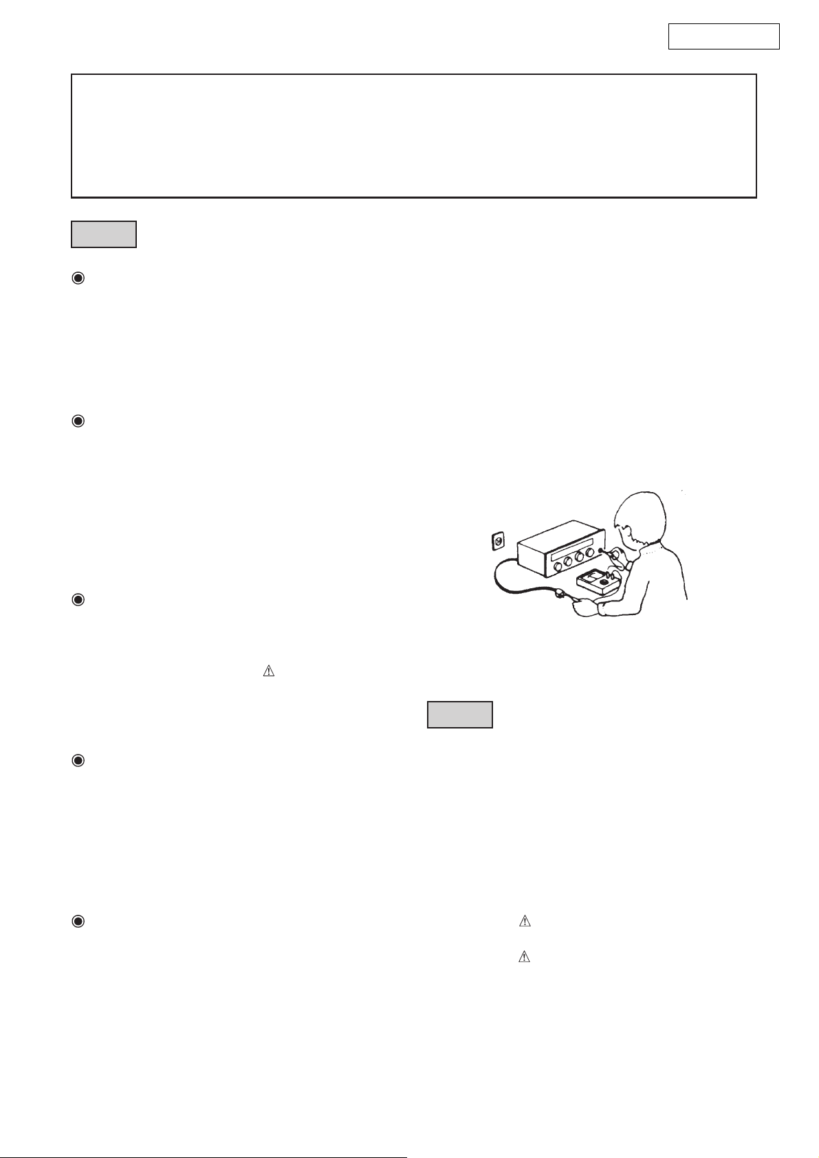
LEAKAGE CURRENT CHECK
Before returning the unit to the customer, make sure you make either (1) a leakage current check or (2) a line to chassis
resistance check. If the leakage current exceeds 0.5 milliamps, or if the resistance from chassis to either side of the
power cord is less than 460 kohms, the unit is defective.
注 意
注意事項をお守りください!
サービスのとき特に注意を必要とする個所について
は、キャビネット、部品、シャーシなどにラベルや
捺印で、注意事項を表示しています。これらの注意
書きおよび取扱説明書などの注意事項を必ずお守り
ください。
感電に注意!
(1)このセットは、交流電圧が印加されていますの
で、通電時に内部金属部に触れると感電するこ
とがあります。従って通電サービス時には、絶
縁トランスの使用や手袋の着用、部品交換に
は、電源プラグを抜くなどして、感電にご注意
ください。
(2)内部には、高電圧の部分がありますので、通電
時の取扱には、十分ご注意ください。
指定部品の使用!
セットの部品は難燃性や耐電圧など安全上の特性を
持ったものとなっています。従って交換部品は、使
用されていたものと同じ特性の部品を使用してくだ
さい。特に配線図、部品表に
安全上重要な部品は必ず指定のものをご使用くださ
い。
サービス、点検時には次のことにご注意願います。
印で指定されている
(絶縁チェックの方法)
電源コンセントから電源プラグを抜き、アンテナ
や、プラグなどを外し、電源スイッチを入れま
す。500V絶縁抵抗計を用いて、電源プラグのそれ
ぞれの端子と、外部露出金属部〔アンテナ端子、
ヘッドホン端子、マイク端子、入力端子など〕と
の間で、絶縁抵抗値が1MΩ以上であること、この
値以下のときは、セットの点検修理が必要です。
安全上重要な部品について
注 意
注 意
安全上重要な部品について
部品の取付けや配線の引きまわしは、元どおりに!
安全上、テープやチューブなどの絶縁材料を使用し
たり、プリント基板から浮かして取付けた部品があ
ります。また内部配線は引きまわしやクランパーに
よって発熱部品や高圧部品に接近しないように配慮
されていますので、これらは必ず元どおりにしてく
ださい。
サービス後は安全点検を!
サービスのために取り外したねじ、部品、配線など
が元どおりになっているか、またサービスした個所
の周辺を劣化させてしまったところがないかなどを
点検し、外部金属端子部と、電源プラグの刃の間の
絶縁チェックをおこなうなど、安全性が確保されて
いることを確認してください。
本機に使用している多くの電気部品、および機構部品
は安全上、特別な特性を持っています。この特性はほ
とんどの場合、外観では判別つきにくく、また、もと
の部品より高い定格(定格電力、耐圧)を持ったもの
を使用しても安全性が維持されるとは、限りません。
安全上の特性を持った部品は、このサービスマニュア
ルの配線図、部品表につぎのように表示していますの
で、必ず指定されている部品番号のものを使用願いま
す。
(1) 配線図…
(2) 部品表… マークで表示しています。
マークで表示しています。
指定された部品と異なるものを使用し
た場合には、感電、火災などの危険を
生じる恐れがあります。
2
Page 3
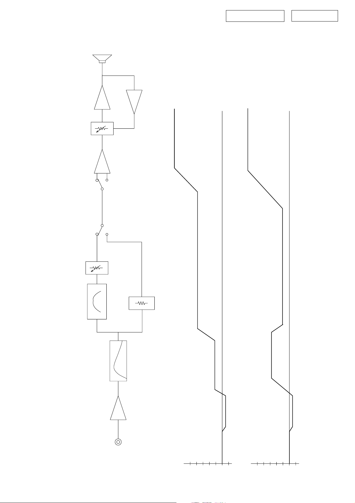
DSW-76 BLOCK / LEVEL DIAGRAM
SPEAKER
U203
ALC
POWER AMPREVERSE PHASE
DSW-76 Section
SYS-76HT
U203
NORMAL
SW202
DIRECT
VOL
MODE SW
at 55Hz
+50.5dB 20V/4ohrm THD 0.7% (ALCON)
at 55Hz
20V/4ohrm THD 0.7% (ALCON)
+27.2dB
+1.84dB
CONTROL
CROSSOVER
HPF
U201
LINE INPUT
ATT
DIRECT MODE
(dB)
+20dB
40
+4.34dB
75mV
0
20
-1dB
10
-
(dB)
+4.34dB
20
40
-1dB
830mV
0
10
-
3
Page 4
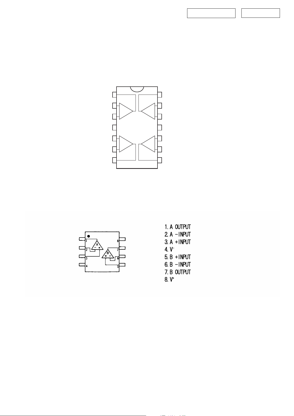
DSW-76 SEMICONDUCTORS
Only major IC's are shown,generai IC's etc. are omitted to list.
主な半導体を記載しています。汎用の半導体は記載を省略しています。
IC's
TL074CN (U201-203) PRE-AMP P.W.B. UNIT
DSW-76 Section
SYS-76HT
CC
1
2
-
+
3
+
4
5
+
-
6
7
-
+
+
-
Output 1
Inverting Input 1
Non-inverting Input 1
V
Non-inverting Input 2
Inverting Input 2
Output 2
NJM4558D (U101) AMP P.W.B. UNIT
14
Output 4
13
Inverting Input 4
12
Non-inverting Input 4
-
V
11
CC
10
Non-inverting Input 3
9
Inverting Input 3
8
Output 3
4
Page 5
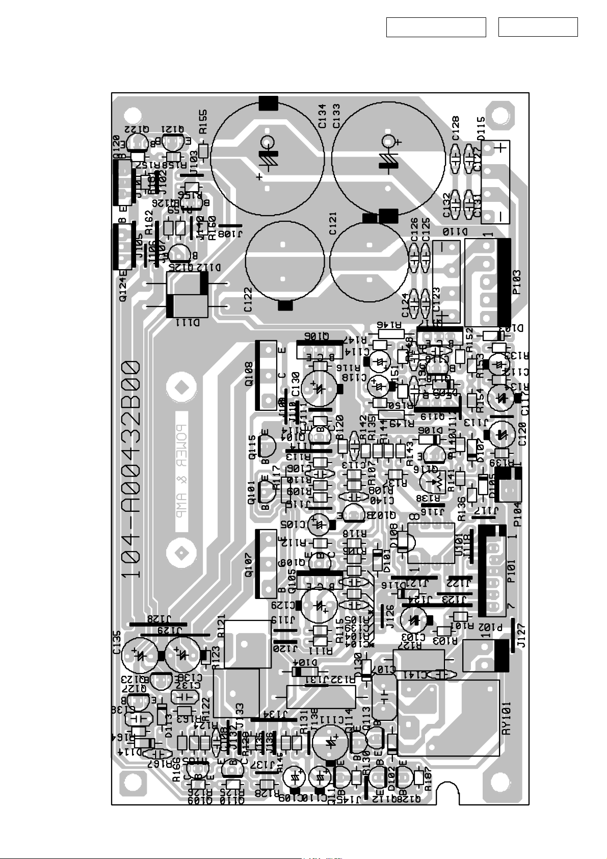
DSW-76 PRINTED WIRING BOARDS (1/2)
AMP P.W.B. UNIT
DSW-76 Section
SYS-76HT
5
Page 6
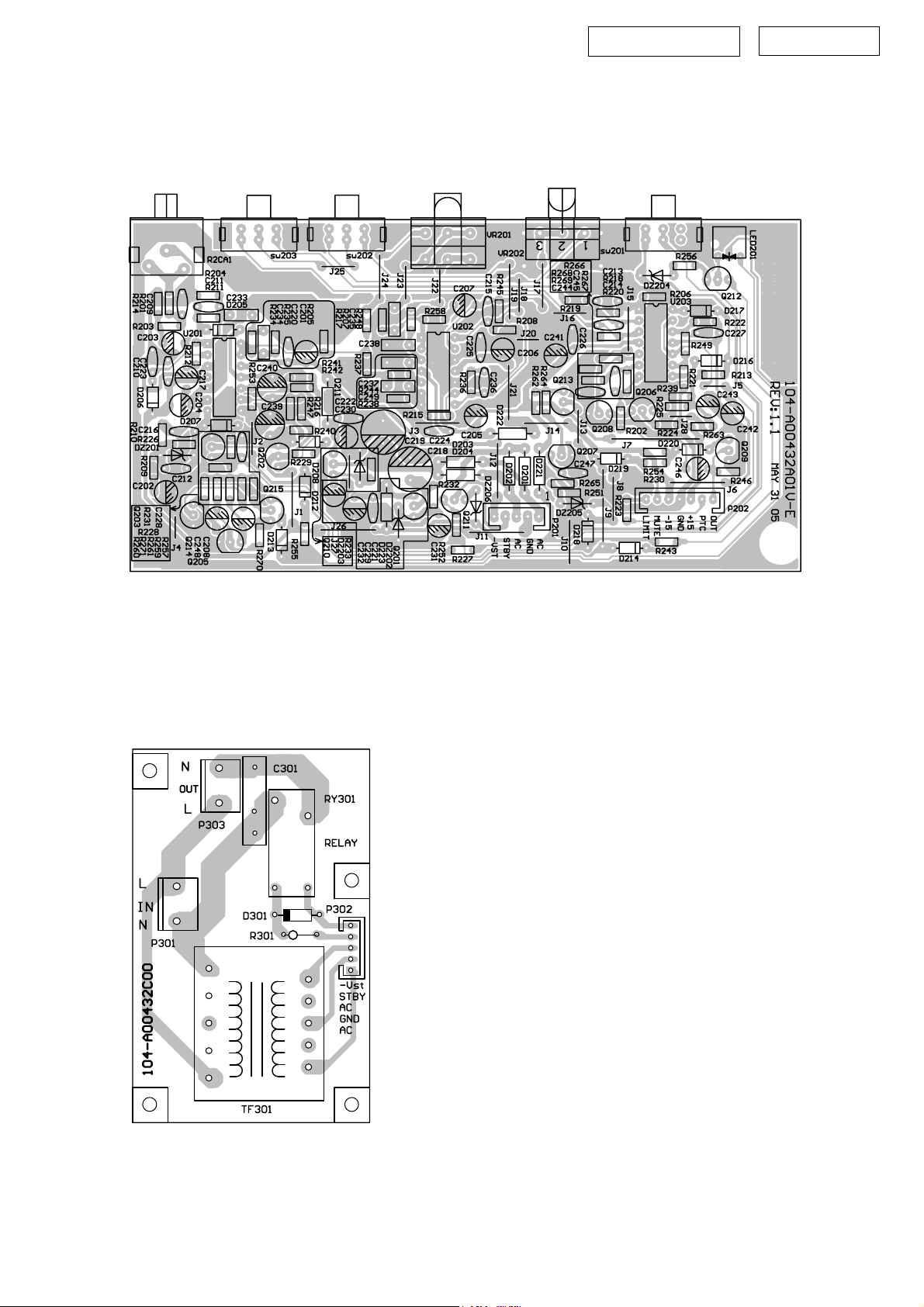
DSW-76 PRINTED WIRING BOARDS (2/2)
PRE-AMP P.W.B. UNIT
DSW-76 Section
SYS-76HT
POWER P.W.B. UNIT
6
Page 7
DSW-76 Section
SYS-76HT
NOTE FOR PARTS LIST
• Part indicated with the mark "nsp" are not always in stock and possibly to
take a long period of time for supplying, or in some case supplying of part
may be refused.
• When ordering of part, clearly indicate "1" and "I" (i) to avoid mis-
supplying.
• Ordering part without stating its part number can not be supplied.
• Part indicated with the mark " ★ " is not illustrated in the exploded view.
• Not including Carbon Film Resister ±5%, 1/4W Type in the P.W.Board
parts list. (Refer to the Schematic Diagram for those parts.)
• Not including Carbon Chip Resister 1/16W Type in the P.W.Board parts
list. (Refer to the Schematic Diagram for those parts.)
WARNING:
Parts marked with this symbol
Use ONLY replacement parts recommended by the manufacturer.
ll
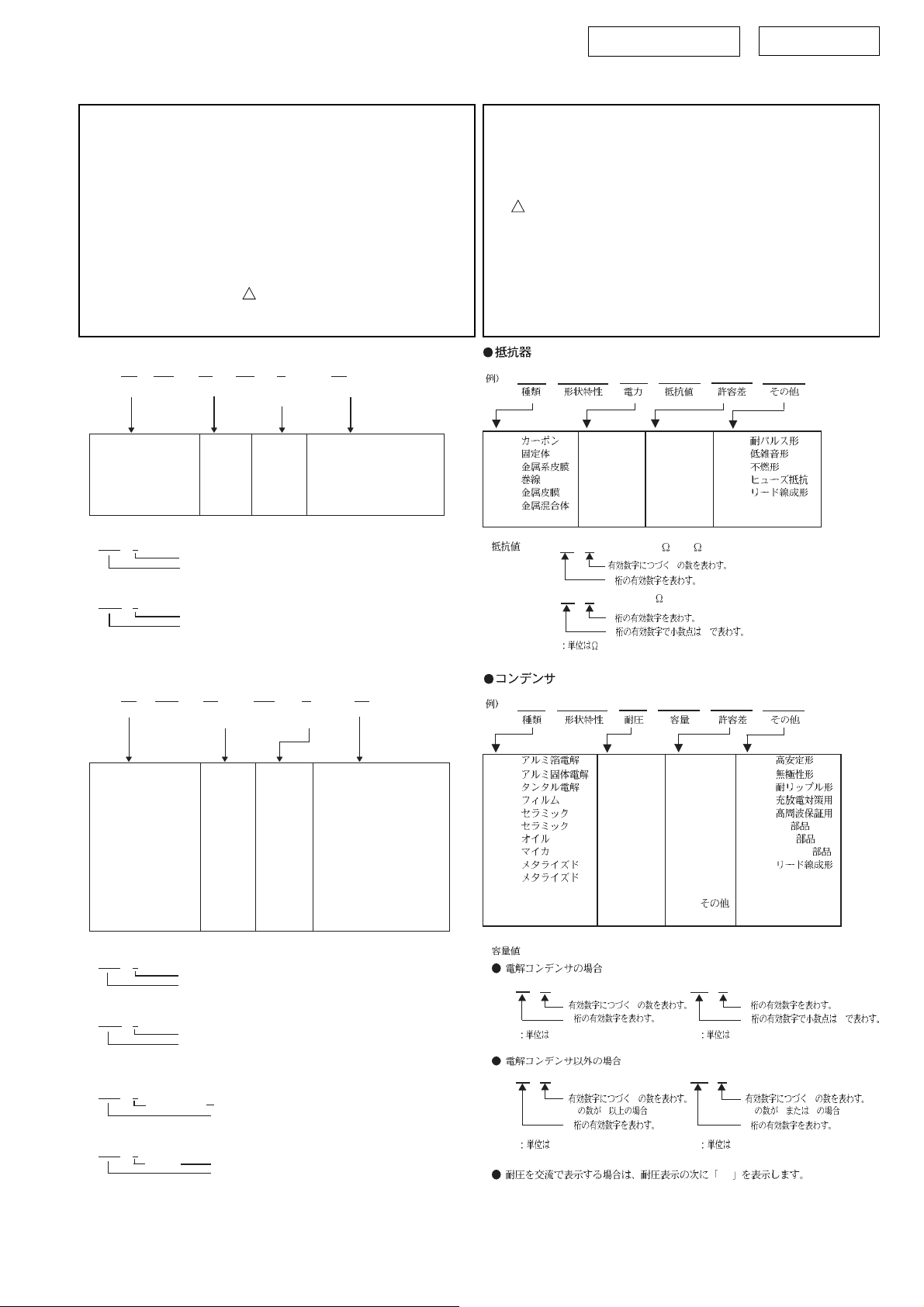
l Resistors
ll
Ex.: RN 14K 2E 182 G FR
Type Shape Power Resist- Allowable Others
and per- ance error
formance
RD : Carbon 2B : 1/8W F : ±1% P : Pulse-resistant type
RC : Composition 2E : 1/4W G : ±2% NL : Low noise type
RS : Metal oxide film 2H : 1/2W J : ±5% NB : Non-burning type
RW : Winding 3A : 1W K : ±10% FR : Fuse-resistor
RN : Metal film 3D : 2W M : ±20% F : Lead wire forming
RK : Metal mixture 3F : 3W
] Resistance
1 8 2 ⇒ 1800 ohm = 1.8 kohm
s
s
• Units: ohm
1 R 2 ⇒ 1.2 ohm
s
s
• Units: ohm
Indicates number of zeros after effective number.
2-digit effective number.
1-digit effective number.
2-digit effective number, decimal point indicated by R.
! have critical characteristics.
3H : 5W
部品表について
1.nsp 印の部品は常時在庫していませんので供給に長時間を要すること
があります。
場合によっては、供給をお断りすることがあります。
2.部品を発注する際は特に数字の " 1 " と英字の "I" との区別をはっき
り記入してください。
3.部品番号を表示していない部品は供給できません。
!印の部品は安全上重要な部品です。交換するときは、安全および性
4.
能維持のため必ず指定の部品をご使用ください。
5.★印のついている部品は分解図中には記載していません。
6.カーボン抵抗器± 5%、1/4W 型は記載していません。定数は回路図を
参照願います。
7.カーボンチップ抵抗器 1/16W 型は記載していません。定数は回路図を
参照願います。
8.部品表の抵抗器、コンデンサの品名記号の読み方は表を参照してくだ
さい。
RN 14K 2E 182 G FR
RD : 2B : 1/8 W F : ±1% P :
RC : 2E : 1/4 W G : ±2% NL :
RS : 2H : 1/2 W J : ±5% NB :
RW : 3A : 1 W K : ±10% FR :
RN : 3D : 2 W M : ±20% F :
RK : 3F : 3 W
∗
18 2
1R 2
3H : 5 W
1800
Ö
2
1.2
Ö
1
2 R
=1.8k
0
ll
Capacitors
l
ll
Ex.: CE 04W 1H 2R2 M BP
Type Shape Dielectric Capacity Allowable Others
and per- strength error
formance
CE : Aluminum foil 0J : 6.3V F : ±1% HS : High stability type
electrolytic
CA : Aluminum solid 1A : 10V G : ±2% BP : Non-polar type
electrolytic
CS : Tantalum electrolytic 1C : 16V J : ±5% HR : Ripple-resistant type
CQ : Film 1E : 25V K : ±10% DL : For change and discharge
CK : Ceramic 1V : 35V M : ±20% HF : For assuring high
CC : Ceramic 1H : 50V Z : +80% U : UL part
CP : Oil 2A : 100V –20% C : CSA part
CM : Mica 2B : 125V P : +100% W : UL-CSA type
CF : Metallized 2C : 160V –0% F : Lead wire forming
CH : Metallized 2D : 200V C : ±0.25pF
] Capacity (electrolyte only)
2 2 2 ⇒ 2200µF
s
s
• Units: µF.
2 R 2 ⇒ 2.2µF
s
s
• Units: µF.
] Capacity (except electrolyte)
2 2 2 ⇒ 2200pF=0.0022µF
s
s
(More than 2) Indicates number of zeros after effective number.
• Units: pF.
2 2 1 ⇒ 220pF
s
s
(0 or 1) Indicates number of zeros after effective number.
• Units: pF.
• When the dielectric strength is indicated in AC, "AC" is included after the dieelectric
strength value.
2E : 250V D : ±0.5pF
2H : 500V = : Others
2J : 630V
Indicates number of zeros after effective number.
2-digit effective number.
1-digit effective number.
2-digit effective number, decimal point indicated by R.
2-digit effective number.
2-digit effective number.
requency
CE 04W 1H 2R2 M BP
CE : 0J : 6.3 V F : ±1% HS :
CA : 1A : 10 V G : ±2% BP :
CS : 1C : 16 V J : ±5% HR :
CQ : 1E : 25 V K : ±10% DL :
CK : 1V : 35 V M : ±20% HF :
CC : 1H : 50 V Z : +80% U : UL
CP : 2A : 100 V −20% C : CSA
CM : 2B : 125 V P : +100% W : UL-CSA
CF : 2C : 160 V − 0% F :
CH : 2D : 200 V C : ±0.25pF
2E : 250 V D : ±0.5pF
2H : 500 V = :
2J : 630 V
∗
22 2
22 2
2200µF
Ö
2
µ
F
2200pF=0.0022µF
Ö
(0 2 )
2
p
F
0
0
2R 2
22 1
Ö
1
2 R
µ
F
Ö
(0 0 1 )
2
p
F
AC
2.2µF
220pF
0
7
Page 8
DSW-76 Section
SYS-76HT
PARTS LIST OF P.W.B. UNIT ASS’Y
*本表に記載されている部品は、補修用部品のため製品に使用している部品とは一部、形状、寸法などが異なる場合があります。
* The parts listed below are for maintenance only, might differ from the parts used in the unit in appearances or dimensions.
*"nsp" 印の部品は常時在庫していませんので供給に長時間を要することがあります。場合によっては、供給をお断りする場合があります。
* Part indicated with the mark “nsp” are not always in stock and possibly to take a long period of time for supplying, or in some case supplying of part may be refused.
Note: The symbols in the column "Remarks" indicate the following destinations.
PRE-AMP P.W.B. UNIT ASS'Y
Ref. No nsp Part No. Part Name Remark Q'ty New
SEMICONDUCTORS GROUP
U201-203 00D DSW 7601 025 TL074CN 190-16t1074cn-e
Q201-203 00D DSW 7601 028 TR2SC1815GR 192-027c1815gr-e
Q205-209 00D DSW 7601 028 TR2SC1815GR 192-027c1815gr-e
Q214-215 00D DSW 7601 028 TR2SC1815GR 192-027c1815gr-e
Q210-213 00D DSW 7601 030 TR2SA1015GR 192-028a1015gr-e
D201-204 00D DSW 7601 043 D 1N4002 197-101n4002-e
D205-208 00D DSW 7601 042 D 100mA 1N4148/75V 197-031n4148-e
D211 00D DSW 7601 043 D 1N4002 197-101n4002-e
D212-220 00D DSW 7601 042 D 100mA 1N4148/75V 197-031n4148-e
D221-223 00D DSW 7601 043 D 1N4002 197-101n4002-e
DZ201 00D DSW 7601 048 ZD 1/2W/3.3V 199-15000335-e
DZ202,203 00D DSW 7601 046 ZD 1/2W/12V 199-05001203j-e
DZ204-206 00D DSW 7601 044 ZD 1/2W/2.4V 199-05000243j-e
LED201 00D DSW 7601 040 LED 195-10339evg-e
RESISTER GROUP
VR201 00D DSW 7601 010 VAR R 115-h203b214-e
VR202 00D DSW 7601 011 VAR R 115-h503a102-e
CAPACITORS GROUP
C201-204 - ERECTRIC C 10uF/16V 135-3106m16-e
C205,206 - ERECTRIC C 10uF/25V 135-3106m25-e
C207 - ERECTRIC C 10uF/16V 135-3106m16-e
C208 - ERECTRIC C 47U/25V 135-3476m25-e
C209-215 - CERAMIC C 220P/50V 130-2b221k503-e
C216 - CERAMIC C 47P/50V 130-2b470k503-e
C217 - ERECTRIC C 1UF/16V 135-3105m16-e
C218,219 - ERECTRIC C 220uF/25V 135-3227m25-e
C220-228 - CERAMIC C 0.1U/50V 130-3f104z503-e
C229,230 - ERECTRIC C 47U/25V 135-3476m25-e
C231,232 - ERECTRIC C 10uF/16V 135-3106m16-e
C233-235 - FILM C 0.1U/63V 129-a104j633-e
C236 - CERAMIC C 1000P/50V 130-2b102k503-e
C237 - FILM C 0.22uF/63V 129-a223j633-e
C238 - FILM C 0.047U/63V 129-a473j633-e
C239 - ERECTRIC C 100uF/16V 135-3107m16-e
C240 - ERECTRIC C 4.7U/16V 135-3475m16-e
C241,242 - ERECTRIC C 10uF/25V 135-3106m25-e
8
Page 9

DSW-76 Section
SYS-76HT
Ref. No nsp Part No. Part Name Remark Q'ty New
C243 - ERECTRIC C 100UF/25V 135-3107m25-e
C244,245 - FILM C 10NF/63V 129-a103j633-e
C246 - ERECTRIC C 47U/25V 135-3476m25-e
C247 - CERAMIC C 0.01U/50V 130-2b103k503-e
C248 - ERECTRIC C 47U/25V 135-3476m25-e
C249 - FILM C 0.15U/63V 129-a154j633-e
OTHER PARTS DROUP
P201 - 7PIN WIRE/BLK/WHT 162-5015d005-e *
P201 - 5PIN CONNECTOR 175-1c05v01-e
RCA1 - RCA-209A/BLK 174-0rca209u-e *
SW201-203 00D DSW 7601 023 MS7210V/6PIN 180-tms7210v-e *
- LED HOLDER7.5*7.1*8.25
361-NYL-05012-0BAE
*
AMP P.W.B. UNIT ASS'Y
Ref. No nsp Part No. Part Name Remark Q'ty New
SEMICONDUCTORS GROUP
U101 00D DSW 7601 024 4558D 190-06m4558d-e
Q101,102 00D DSW 7601 028 TR2SC1815GR 192-027c1815gr-e
Q103 00D DSW 7601 032 TR2N5551 192-1572n5551-e
Q104 00D DSW 7601 033 TR2N5401 192-1582n5401-e
Q105 00D DSW 7601 039 TRHSB649T 192-992b649t-e
Q106 00D DSW 7601 038 TRHSD669A 192-991d669a-e
Q107 00D DSW 7601 026 TRTIP35C 192-021tip35c-e
Q108 00D DSW 7601 027 TRTIP36C 192-022tip36c-e
Q109 00D DSW 7601 032 TR2N5551 192-1572n5551-e
Q110 00D DSW 7601 033 TR2N5401 192-1582n5401-e
Q111-113 00D DSW 7601 028 TR2SC1815GR 192-027c1815gr-e
Q114 00D DSW 7601 030 TR2SA1015GR 192-028a1015gr-e
Q115 00D DSW 7601 028 TR2SC1815GR 192-027c1815gr-e
Q116 00D DSW 7601 030 TR2SA1015GR 192-028a1015gr-e
Q117 00D DSW 7601 034 TRTIP31C 192-161tip31c-e
Q118 00D DSW 7601 028 TR2SC1815GR 192-027c1815gr-e
Q119 00D DSW 7601 037 TRKSB772Y 192-202b772y-e
Q120 00D DSW 7601 036 TRTIP42C 192-162tip42c-e
Q121 00D DSW 7601 029 TR2SC2235Y 192-027c2235y-e
Q122 00D DSW 7601 030 TR2SA1015GR 192-028a1015gr-e
Q123 00D DSW 7601 028 TR2SC1815GR 192-027c1815gr-e
Q124 00D DSW 7601 035 TRTIP41C 192-161tip41c-e
Q125 00D DSW 7601 031 TR2SA965Y 192-028a965y-e
Q126 00D DSW 7601 028 TR2SC1815GR 192-027c1815gr-e
Q127 00D DSW 7601 030 TR2SA1015GR 192-028a1015gr-e
Q128 00D DSW 7601 030 TR2SA1015GR 192-028a1015gr-e
D101 00D DSW 7601 042 D 1N4148 197-031n4148-e
D102 00D DSW 7601 049 ZD 3.3V 199-15000335-e
9
Page 10

DSW-76 Section
SYS-76HT
Ref. No nsp Part No. Part Name Remark Q'ty New
D103 00D DSW 7601 042 D 1N4148 197-031n4148-e
D105 00D DSW 7601 042 D 1N4148 197-031n4148-e
D106,107 00D DSW 7601 050 ZD 6.2V 199-15000625-e
D108 00D DSW 7601 042 D 1N4148 197-031n4148-e
D109 00D DSW 7601 051 ZD 16V 199-15001605-e
D110 00D DSW 7601 041 D KBL405/500V 197-00kbl405-e
D111,112 00D DSW 7601 055 D 1N5402 97-101n5402-e
D113,114 00D DSW 7601 042 D 1N4148 197-031n4148-e
D115 00D DSW 7601 041 D KBL405/500V 197-00kbl405-e
D117,118 00D DSW 7601 042 D 1N4148 197-031n4148-e
D130 00D DSW 7601 047 D 500mW/24V 199-05002403j-e
RESISTER GROUP
R121,122 00D DSW 7601 008 R 0.1ɹ/5W 113-500r1j10-e
R132 00D DSW 7601 006 R 1K/2W 110-20102jk2-e
R138 00D DSW 7601 009 SEMI VAR. R 3K/0.3W 114-03302m0-e
R167 00D DSW 7601 005 R TTC-802(JS)/NTC 109-1ttc802j0-e
CAPACITORS GROUP
C103 - ERECTRIC C 47U/25V 135-3476m25-e
C104 - CERAMIC C 100P/50V 130-sl101k503-e
C105 - ERECTRIC C 1U/50V 135-3105m50-e
C106 - CERAMIC C 0.047U/50V 130-3f473m503-e
C107 - FILM C 0.1U/50V 132-104j503-e
C108 - CERAMIC C 0.1U/50V 30-3f104z503-e
C109,110 - ERECTRIC C 100uF/16V 135-3107m16-e
C111 - ERECTRIC C 220U/16V 135-3227m16-e
C112 - ERECTRIC C 4.7U/50V 135-3475m50-e
C113 - CERAMIC C 0.1U/50V 30-3f104z503-e
C114 - ERECTRIC C 22U/50V 135-3226m50-e
C115 - CERAMIC C 0.1U/50V 30-3f104z503-e
C116 - CERAMIC C 1000P/50V 130-2b102k503-e
C117 - ERECTRIC C 100U/25V 135-3107m25-e
C118 - ERECTRIC C 22U/50V 135-3226m50-e
C119 - CERAMIC C 0.1U/50V 30-3f104z503-e
C120 - ERECTRIC C 100U/25V 135-3107m25-e
C121,122 00D DSW 7601 012 ERECTRIC C 4700uF/35V 135-4478m35-e
C123-128 - FILM C 0.022uF/100V 132-223ja03-e
C129,130 - ERECTRIC C 220U/10V 135-3227m10-e
C131,132 - FILM C 0.022uF/100V 132-223ja03-e
C133,134 00D DSW 7601 013 ERECTRIC C 4700uF/63V 135-4478m63-e
C135,136 - ERECTRIC C 100U/50V 135-3107m50-e
C137,138 - CERAMIC C 0.1U/50V 30-3f104z503-e
C139,140 - CERAMIC C 100P/50V 130-sl101k503-e
C141 - CERAMIC C 1000P/50V 130-2b102k503-e
OTHER PARTS DROUP
P101 - 7PIN CONNECTOR 175-1c07v01-e
P102 - 2PIN CONNECTOR 175-1d02v01-e
P103 - 5PIN CONNECTOR 175-1d05v01-e
P104 - 2PIN CONNECTOR 175-1c02v01-e
RY101 00D DSW 7601 054 RELAY/24V 71-udhss124d-e *
10
Page 11

DSW-76 Section
Ref. No nsp Part No. Part Name Remark Q'ty New
- TUBE 1M*10mm 156-h010010-e
- SHEET 361-NYL-00054-0LAE *
- TR BLACKET 361-FE-00051-0LAE *
- HEAT SINK 323-AL-00020-0LAE *
- M3*14 SCREW 351-AM03014A094-J
- M3*8 SCREW 352-AM03008D040-J *
POWER P.W.B. UNIT ASS'Y
Ref. No nsp Part No. Part Name Remark Q'ty New
SEMICONDUCTORS GROUP
D301 00D DSW 7601 045 D 1/2W/12V 199-05001200j-e
RESISTER GROUP
R301 00D DSW 7601 007 R 0.56K/2W 110-20561jk3-e
SYS-76HT
CAPACITORS GROUP
C301 - FILM C 0.01uF/275V 132-103kb74-e
OTHER PARTS DROUP
P301 - 3PIN CONNECTOR 175-1d03v04-e
P302 - 5PIN CONNECTOR WIRE 162-5026d001-e *
P303 - 3PIN CONNECTOR 175-1d03v02-e
RY301 00DDSW 7601 056 RELAY 171-cs112lmr-e *
! 00D DSW 7601 015 SUB TRANS for E3 150-e0351201-e *
! 00D DSW 7601 014 SUB TRANS for E2 150-e0351200-e *
- TUBE 1M*10mm 156-h010010-e
11
Page 12

DSW-76 EXPLODED VIEW
Parts marked with this symbol have critical
characteristics.
Use ONLY replacement parts recommended by
the manufacturer.
WARNING:
印の部分は安全を維持するために重要
な部品です。従って交換時は必ず指定の
部品を使用してください。
1
DSW-76 Section
SYS-76HT
2
104
103
101
29
28
30
101
6
4
3
5
34
32
31
33
35
11
14
15
16
17
27
12
18
13
19
101
23
22
20
21
102
101
24
105
26
8
7
102
25
12
Page 13

DSW-76 Section
SYS-76HT
PARTS LIST OF EXPLODED VIEW
*本表に記載されている部品は、補修用部品のため製品に使用している部品とは一部、形状、寸法などが異なる場合があります。
* The parts listed below are for maintenance only, might differ from the parts used in the unit in appearances or dimensions.
*"nsp" 印の部品は常時在庫していませんので供給に長時間を要することがあります。場合によっては、供給をお断りする場合があります。
* Part indicated with the mark “nsp” are not always in stock and possibly to take a long period of time for supplying, or in some case supplying of part may be refused.
Note: The symbols in the column "Remarks" indicate the following destinations.
E3:U.S.A. & Canada Model E2: Europe Model
Ref. No. nsp Part No. Part Name Remark Q'ty New
1 nsp 00D DSW 7600 001 Cabinet Ass'y BHKXDN055000 1 *
2 00D DSW 7600 002 Woofer LB7430400001 1 *
3 nsp 00D DSW 7600 003 Oak Feet JD5081000014 4
4 00D DSW 7600 004 Spikes JZ0071000002 4
5 nsp 00D DSW 7600 005 Screw LS1215010004 8
6 nsp 00D DSW 7600 006 Screw LS1215B07002 4
7 - Rear Sticker YS0480610019 1 *
11 nsp 00D DSW 7601 001 PREAMP P.W.B. UNIT 051-A00432A-E 1
12 nsp 00D DSW 7601 002 AMP P.W.B. UNIT 051-A00432B-E 1
13 nsp 00D DSW 7601 004 POWER P.W.B. UNIT for E3 051-A00434C-E 1
13 nsp 00D DSW 7601 003 POWER P.W.B. UNIT for E2 051-A00432C-E 1
14 - EVA 333-EVA-00783-0BAE 2
15 - WIRE CLAMP 163-11009-e 2
16 - EVA 333-EVA-00807-0BAE 2
17 - CASE 306-ABS-00206-1BBE 1
18 - BRACKET Large-R 361-FE-05008-0LBE 1
19 - HEAT SINK 309-ABS-05003-0BAE 1
! 20 00D DSW 7601 015 SUB TRANS for E3 150-e0351201-e 1
! 20 00D DSW 7601 014 SUB TRANS for E2 150-e0351200-e 1
21 - BRACKET Small-L 361-FE-05010-0LAE 1
22 - BRACKET Small-R 361-FE-05011-0LAE 1
23 nsp 00D DSW 7601 053 BACK PANEL for E3 302-AL-05021-2BBE 1
23 nsp 00D DSW 7601 052 BACK PANEL for E2 302-AL-05021-1BAE 1
! 24 00D DSW 7601 022 POWER SWITCH 180-prf1003s-e 1
! 25 00D DSW 7601 018 AC COARD for E3 152-u75201601-e 1
! 25 00D DSW 7601 019 AC COARD for E2 152-v75202601-e 1
26 - COVER 309-ABS-05003-0BAE 1
27 - HEAT SINK 323-AL-00019-0BBE 1
28 - BUSH 335-NYL-00002-0BAE 2
29 - RUBBER SHEET 25*21*2T 336-RUB-00263-0BAE 4
! 30 00D DSW 7601 017 MAIN TRANS for E3 150-e0865005-e 1
! 30 00D DSW 7601 016 MAIN TRANS for E2 150-e0865004-e 1
31 - M4 NUT 354-GM04002-J 4
32 - PWB HOLDER 61-FE-05013-0LAE 1
33 - EVA 333-EVA-00835-0BAE 2
34 - BRACKET Large-L 361-FE-05008-0LAE 1
35 - EVA 333-EVA-00826-0BAE 2
! 36 00D DSW 7601 020 FUSE 125V for E3 154-u25002t0-e 1
! 36 00D DSW 7601 021 FUSE 250V for E2 154-v12506t0-e 1
! 37 - CERAMIC C 4700P 130-3f472md00-e 1
38 - FUSE HOLDER R3-11 155-520020-e 1
39 - TUBE 20mm*40mm 156-h200040-e 1
40 - TUBE 20mm*60mm 156-h200060-e 1
41 - TUBE 7mm*120mm 156-h070120-e 1
43 - LED HOLDER7.5*7.1*8.25 361-NYL-05012-0BAE 1
45 - EVA 333-EVA-00220-0BAE 6
46 - EVA 333-EVA-05052-0BAE 4
13
Page 14

DSW-76 Section
SYS-76HT
Ref. No. nsp Part No. Part Name Remark Q'ty New
101 - M3*8 SCREW 351-AM03008A079-J 19
102 - M3*8 SCREW 352-AM03008D040-J 14
103 - M3*10 SCREW 352-BM03010D064-J 2
104 - M3*14 SCREW 351-BM03014A093-J 1
105 - M4*16 SCREW 351-HM04016A218-J 4
106 - M3*10 SCREW 352-AM03010D065-J 1
107 - M3*14 SCREW 351-BM03014A093-J 1
108 - 4M*12 SCREW 350-EM04012D024-J 10
14
Page 15

SC-C76 EXPLODED VIEW
SC-C76/SC-A76 Section
SYS-76HT
7
6
4
102
3
7
1
101
3
101
5
8
2
SC-C76 PARTS LIST OF EXPLODED VIEW
※ 本表に記載されている部品は、補修用部品のため製品に使用している部品とは一部、形状、寸法などが異なる場合があります。
※ Thepartslistedbelowareformaintenanceonly,mightdifferfromthepartsusedintheunitinappearancesordimensions.
※ "nsp" 印の部品は常時在庫していませんので供給に長時間を要することがあります。場合によっては、供給をお断りする場合があります。
Part indicated with the mark “nsp” are not always in stock and possibly to take a long period of time for supplying, or in some case supplying of part may be refused.
※
Ref. No. nsp Part No. Part Name Remark Q'ty New
1 nsp 00D SCC 7600 009 Cabinet Ass'y BHKXDN054001 1 *
2 00D SCC 7600 010 Tweeter Ass'y BHXGDN054001 1 *
3 00D SCC 7600 001 Woofer Ass'y LB0301210005 2 *
4 - Crossover Ass'y BHFYDN054000 1 *
5 00D SCC 7600 003 Grill Ass'y BHBKDN054001 1 *
6 - Rear Sticker YS0480610018 1 *
7 - Wall Bracket GG1510000006 2 *
8 nsp 00D SCA 7600 012 Holder MK0024000001 4 *
101 nsp 00D SCC 7600 007 Screw 4*20 LS4212707001 12
102 - Screw 3.5*16 LS4211905001 8 *
15
Page 16

SC-A76 EXPLODED VIEW
101
8
SC-C76/SC-A76 Section
SYS-76HT
6
4
102
7
1
3
101
2
5
SC-A76 PARTS LIST OF EXPLODED VIEW
※ 本表に記載されている部品は、補修用部品のため製品に使用している部品とは一部、形状、寸法などが異なる場合があります。
※ Thepartslistedbelowareformaintenanceonly,mightdifferfromthepartsusedintheunitinappearancesordimensions.
※ "nsp" 印の部品は常時在庫していませんので供給に長時間を要することがあります。場合によっては、供給をお断りする場合があります。
Part indicated with the mark “nsp” are not always in stock and possibly to take a long period of time for supplying, or in some case supplying of part may be refused.
※
Ref. No. nsp Part Name Remark Q'ty New
1 nsp 00D SCA 7600 010 Cabinet Ass'y BHKXDN053005 1 *
2 00D SCA 7600 011 Tweeter Ass'y BHXGDN053001 1
3 00D SCA 7600 001 Woofer Ass'y LB0300610005 1 *
4 - Crossover Ass'y BHFYDN053000 1 *
5 00D SCA 7600 003 Grill Ass'y BHBKDN053000 1 *
6 - Rear Sticker for FL YS0480610012 1 *
6 - Rear Sticker for FR YS0480610013 1 *
6 - Rear Sticker for SBL YS0480610014 1 *
6 - Rear Sticker for SL YS0480610015 1 *
6 - Rear Sticker for SR YS0480610016 1 *
6 - Rear Sticker for SBR YS0480610017 1 *
7 - Wall Bracket GG1510000006 1
8 nsp 00D SCA 7600 012 Holder MK0024000001 4
101 nsp 00D SCC 7600 007 Screw 4*20 LS4212707001 8
102 - Screw 3.5*16 LS4211905001 4 *
16
Page 17

PACKING VIEW
202
205
209
210
211
SYS-76HT
212 225
213
213
213
222
223
217
206
204
203
201
208
207
218
219
224
220
213
221
PARTS LIST OF PACKING & ACCESSORIES
※ 本表に記載されている部品は、補修用部品のため製品に使用している部品とは一部、形状、寸法などが異なる場合があります。
※ Thepartslistedbelowareformaintenanceonly,mightdifferfromthepartsusedintheunitinappearancesordimensions.
※ "nsp" 印の部品は常時在庫していませんので供給に長時間を要することがあります。場合によっては、供給をお断りする場合があります。
Part indicated with the mark “nsp” are not always in stock and possibly to take a long period of time for supplying, or in some case supplying of part may be refused.
※
Ref. No. nsp Part No. Part Name Remark Q'ty New
201 - Speaker Ass'y SC-A76 6 *
202 - Speaker Ass'y SC-C76 1 *
203 nsp 00D DSW 76E3 001 Speaker Ass'y for E3 CP10DN055000 1 *
203 nsp 00D DSW 76E2 001 Speaker Ass'y for E2 CP10DN055001 1 *
204 nsp 00D SCA 7600 012 Microfoam BHSHDN056001 6 *
205 nsp 00D SCC 7600 011 Microfoam BHSHDN056002 1 *
206 nsp 00D DSW 7601 057 Microfoam BHSHDN056003 1 *
207 - Microfoam BHSHDN053001 6 *
208 - Microfoam BHSHDN054001 1 *
209 nsp 00D SYS 6500 005 Oak Feet JD5081000001 7
210 00D SYS 76HT 001 Owner's Manual YS0170200101 1 *
211 nsp 00D SYS 6500 007 Service Card YS1670210002 1
212 - PE Bag BZ1400000002 1 *
213 nsp 00D SYS 76HT 005 Polyfoam Assy BHBLDN056000 1
- Polyfoam(Top) BZ06DN056001
- Polyfoam(Mid) BZ06DN056002
- Polyfoam(Mid) BZ06DN056003
- Polyfoam(Bottom) BZ06DN056004
217 nsp 00D SYS 76HT 002 Carton Box BZ01DN071001 1 *
218 00D SYS 6500 013 Wire DX2022357001 4
219 00D SYS 6500 014 Wire DX4000020002 1
220 00D SYS 76HT 003 Wire BHSJ00000018 3 *
221 - PE Bag BZ1400000002 1 *
222 - Bar Code Label for E2 YS1370210209 1 *
222 - Bar Code Label for E3 YS1370210210 1 *
223 - Control Card YS0570210064 2 *
224 - Caution Label YS1770200005 1
225 - Warranty Card for E3 TS0270200013 1 *
17
Page 18

DSW-76 WIRING DIAGRAM
LI MI T
AMP P.W.B. UNIT
DSW-76 Section
AC2
AC4
PGND
AC3
AC1
PGND
PGND
MUTE
-15V
AGND
+15V
PTC
in
SYS-76HT
PRE AMP P.W.B. UNIT
POWER P.W.B. UNIT
SIGNAL IN
SIGNAL IN
12VAC
LI MI T
-12V
-12V
MUTE
STBY
STBY
AC
-15V
AGND
AC1
AC2
12VAC
12VAC
PGND
AC
PTC
+15V
PGND
PGND
OUT
AC-ST
AC
12VAC
POW ER
18
Page 19

DSW-76 Section
SYS-76HT
NOTE FOR SCHEMATIC DIAGRAM
WARNING:
Parts marked with this symbol have critical characteristics.
Use ONLY replacement parts recommended by the manufacturer.
CAUTION:
Before returning the unit to the customer, make sure you make
either (1) a leakage current check or (2) a line to chassis resistance check. If the leakage current exceeds 0.5 milliamps, or if
the resistance from chassis to either side of the power cord is
less than 460 kohms, the unit is defective.
WARNING:
DO NOT return the unit to the customer until the problem is located and corrected.
NOTICE:
ALL RESISTANCE VALUES IN OHM. k=1,000 OHM
M=1,000,000 OHM
ALL CAPACITANCE VALUES IN MICRO FARAD.
P=MICRO-MICRO FARAD
EACH VOLTAGE AND CURRENT ARE MEASURED AT
NO SIGNAL INPUT CONDITION.
CIRCUIT AND PARTS ARE SUBJECT TO CHANGE
WITHOUT PRIOR NOTICE.
!
配線図について
!
印の部品は安全を維持するために重要な部品です。
従って交換時は必ず指定の部品を使用してください。
注)
(1) 指定なき抵抗値は Ω、k は kΩ、M は MΩ を示す。
(2) 指定なきコンデンサーの値は µF、p は pF を示す。
(3) 各部の電圧は無信号の値を示す。
(4) この配線図は基本配線図です。改良等のため変更する
ことがありますのでご了承ください。
19
Page 20

DSW-76 SCHEMATIC DIAGRAMS (1/2)
DSW-76 Section
SYS-76HT
12
C217
1.5k
R201
-12.3V
C201
10u/16V /20%
R203
20k
C209
220p/10%
R209
150
R210
47k
6
5
STBY
-V st
C220
0.1u
C210
220p/10%
C203
10u/16V /20%
R214
220K
DZ 201
1N4733/3.3V
C212
220p/10%
150k
C216
47p/50v/10%
U201B
TL 074
D207
1N4148
11 4
D202
1N4001
D201
1N4001
D204
1N4001
R226
7
D203
1N4001
R231
1k
+13.3V
C218
220u/25V
-13.3V
C232
10u/16v
D205
1N4148
3
2
D206
1N4148
sw201
2
1
3
SW-4
R228
22k
C231
10u/16v
U201A
TL 074
411
R211
18K
C211
220p/10%
5
4
6
R227
22k
Q201
C1815
R232
1k
C219
220u/25V
R233
1k
0.15u/5%
R237
10k 1%
R229
10K
Q210
A 1015
DZ 203
12V
R2CA 1*
1
2
3
R212
33k
TO P104
P201
*
TO P302
C202
10u/16V /20%
1u/16V /20%
5
4
3
2
1
1
C249
D208
1N4148
Q203
C1815
C228
0.1u/10%
DZ 202
12V
3
R204
20K
C204
10u/16V /20%
R244
10k 1%
C237
0.022u/5%
R240
2M EG
C229
47u/25V
C221
0.1U
C230
47u/25V
C233
0.1u/5%
C223
0.1u
6
5
Q202
C1815
C239
100u/16V
D223
1N4001
D211
1N4001
C222
0.1U
R234
10.5K/1%
C234
0.1u/5%
U202B
TL074
11 4
R241
4.7k
R242
100k
+12.3V
-12.3V
-15V
U201C
13
R235
135K/1%
7
+12.3V
C240
4.7u/16V
D221
1N4001
D222
1N4001
12
R215
10k
R238
20k
+15V
R216
6.8k
R247
18k
411
R205
20k
45
8
14
411
D216
1N4148
D217
1N4148
R260
15k
10u/16V /20%
U202A
TL074
C248
47u
TL074
DZ206
2.2v
14
R236
7.5K
1000p/50v/10%
9
10
Q211
A1015
9
10
R253
1M EG
R243
100k
Q212
A1015
1
D214
1N4148
R217
10k
C236
U202D
TL074
11 4
STBY
R252
27K
U201D
11 4
LED201
R2ED/GR2EEN
3
2
1
C
B
E
2
R256
1.2k
DZ204
2.2v
+12.3V
8
TL074
8
3
VR201
20KB
C206
10u/16V /20%
R221
10k
R249
18k
R222
10k
st hi
play low
D212
1N4148
2k
R255
D213
1N4148
-15V
R257
1.2k
Q215
C1815
C235
0.1u/5%
R248
18k
0.047u/5%
C225
0.1u
9
10
13
12
R223
10k
R259
1k
C208
47u/16V
R270
20k Q214
C1815
C238
10u/16v/20%
C241
U203D
TL074
11 4
411
U203C
TL074
C242
10u/16v/20%
R261
15k
2
3
C205
1
R207
20K
+15V
C226
0.1u
R213
33k
C243
22u/25V /20%
-15V
C227
0.1u
R
271
1k
Q205
C1815
R258
5.1K
D218
1N4148
6
+15V
C224
0.1u
C207
10u/16V /20%
R263
12meg
R225
10k
R239
470k
D219
1N4148
TL074
Q207
C1815
VR202
50KA
R245
100k
13
12
Q213
A1015
C215
R224
10k
Q206
C1815
R264
3.3k
220p/10%
411
Q208
C1815
U202C
R208
20k
R266
7.5K/1%
R262
30k
C247
0.01u
14
R265
39K
R251
51K
0.01u/5%
R268
750/1%
2
1
3
+15V
sw202
SW-4
C244
+15V
7
5
6
5
4
6
R267
R269
750/1%
DZ205
2.2v
sw203
2
1
3
SW-4
114
U203B
TL074
7.5k/1%
C245
0.01u/5%
PTC
+0.1V
R219
10k
220P/10%
5
4
6
7
R202
150R
R230
D220
22K
1N4148
R254
1M EG
LI M IT
MU TE
-15V
AGND
+15V
PTC
OUT
SIGNAL LINE
10k
R218
C213
220p/10%
C214
R220
10k
C246
47u/25V /20%
Q209
1815
C
2
3
-15V
+15V
R206
20k
LI M IT
MU TE
411
R246
100K
-15V
U203A
TL074
OUT
P202
*
TO P101
AMP UNIT
8
A
1
B
C
1
2
3
4
5
6
7
D
E
20
Page 21

DSW-76 SCHEMATIC DIAGRAMS (2/2)
DSW-76 Section
SYS-76HT
12
-13.6V
+0.1V
3
45
+23.4V
+48.5V
6
7
8
A
B
-48.5V
-23.4V
+23.8V
+23.4V
-23.8V
+48.5V
E1 : 230V 50Hz
E1C : 220V 50Hz
E1T : 120V 60Hz
C
C301
0.01u/250V AC
P303
2
1
TO CON104
F301
HI
C303
4.7n/250V AC
S1
TF301
A
1
2
1
2 1
P301
L
2
N
K1
12VDC RELAY
D301
12V
R301
560R/2W
AC10.5V
GND
AC10.5V
STBY
-V st
TO P201
P302
1
2
3
4
5
D
TO P104
-23.4V
21
-48.5V
POWER INPUT: FUSE: T RANSFORMER:
AC120V(60HZ)
AC230V (50HZ)
SIGNAL LINE
F301 TF301
1.25A 125VAC
1.25A 250VAC
INPUT 120VAC
INPUT 230AC
POWER UNIT
PRE-AMP UNIT
E
Page 22

DOCUMENTS FOR WEEE
Details of Recycle Parts
*You have to remove the parts that marked “WEEE Mark ◆ " when the recycling processing. (Europe model only)
Recycle Parts for DSW-76
SYS-76HT
Ref. No.
1 Cabinet Ass'y COMPLEX 1
2
3 Oak Feet OAK 4
4 Spikes STEEL 4
5 Screw STEEL 8
6 Screw STEEL 10
7 Rear Sticker 1
8 Screw STEEL 10
11
12
13
13
14 EVA EVA 2
15 WIRE CLAMP 2
16 EVA EVA 2
17 CASE ABS 1
18 BRACKET Large-R STEEL 1
19 HEAT SINK AL 1
20
20
21 BRACKET Small-L STEEL 1
22 BRACKET Small-R STEEL 1
23 BACK PANEL STEEL 1
23 BACK PANEL STEEL 1
24
25
25
26 COVER STEEL 1
27 HEAT SINK AL 1
28 BUSH 2
29 RUBBER SHEET 25*21*2T 4
30
30
31 M4 NUT STEEL 4
32 PWB HOLDER 1
33 EVA EVA 2
34 BRACKET Large-L STEEL 1
35 EVA EVA 2
36 FUSE 125V COMPLEX 1
36 FUSE 250V COMPLEX 1
37
38 FUSE HOLDER R3-11 1
39 TUBE 20mm*40mm 1
40 TUBE 20mm*60mm 1
41 TUBE 7mm*120mm 1
43 LED HOLDER7.5*7.1*8.25 ABS 1
45 EVA EVA 6
46 EVA EVA 4
WEEE
Mark
◆
◆
◆
◆
◆
◆
◆
◆
◆
◆
◆
◆
◆
Woofer COMPLEX 1
PREAMP P.W.B. UNIT COMPLEX 1
AMP P.W.B. UNIT COMPLEX 1
POWER P.W.B. UNIT COMPLEX 1
POWER P.W.B. UNIT COMPLEX 1
SUB TRANS COMPLEX 1
SUB TRANS COMPLEX 1
POWER SWITCH COMPLEX 1
AC CORD COMPLEX 1
AC CORD COMPLEX 1
MAIN TRANS COMPLEX 1
MAIN TRANS COMPLEX 1
CERAMIC C 4700P COMPLEX 1
Part Name Material Q'ty
101 M3*8 SCREW STEEL 19
102 M3*8 SCREW STEEL 14
103 M3*10 SCREW STEEL 2
104 M3*14 SCREW STEEL 1
105 M4*16 SCREW STEEL 4
106 M3*10 SCREW STEEL 1
107 M3*14 SCREW STEEL 1
108 4M*12 SCREW STEEL 4
22
Page 23

Recycle Parts for SC-C76
SYS-76HT
Ref. No.
1
2
2A Cosmetic baffle ABS
2B
3
4
5
6 Rear Sticker PVC 1
7 Wall Bracket STEEL 2
8 Holder TPR 4
101 Screw 4X20 STEEL 12
102 Screw 3.5X16 STEEL 8
WEEE
Mark
◆
◆
◆
◆
◆
◆
Part Name Material Q'ty
Cabinet Ass'y Complex 1
Tweeter Ass'y Complex 1
Tweeter Complex
Woofer Complex 2
Crossover Ass'y Complex 1
Grille Ass'y Complex 1
Recycle Parts for SC-A76
Ref. No.
1
2
2A Cosmetic baffle ABS 1
2B
3
4
5
6 Rear Sticker for FL PVC 1
6 Rear Sticker for FR PVC 1
6 Rear Sticker for SBL PVC 1
6 Rear Sticker for SL PVC 1
6 Rear Sticker for SR PVC 1
6 Rear Sticker for SBR PVC 7
7 Wall Bracket STEEL 1
8 Holder TPR 4
101 Screw 4X20 STEEL 8
102 Screw 3.5X16 STEEL 4
WEEE
Mark
◆
◆
◆
◆
◆
◆
Part Name Material Q'ty
Cabinet Ass'y Complex
Tweeter Ass'y Complex
Tweeter Ass'y Complex 1
Woofer Ass'y Complex 1
Crossover Ass'y Complex
Grille Ass'y Complex
23
Page 24

Exploded view of DSW-76
1
SYS-76HT
You have to remove the parts that marked
"WEEE mark " when the recycling processing.
(Europe model only)
2
27
104
103
101
29
28
30
101
6
4
3
5
33
26
34
35
11
14
15
16
17
12
18
13
21
23
24
105
8
22
101
25
19
101
20
37
32
31
102
7
102
24
Page 25

Exploded view ofSC-C76
SYS-76HT
7
6
4
102
2B2A
3
7
1
101
3
You have to remove the parts that marked
"WEEE mark " when the recycling processing.
(Europe model only)
Exploded view of SC-A76
2B2A
101
8
101
5
8
2
6
4
102
7
1
3
101
2
5
25
You have to remove the parts that marked
"WEEE mark " when the recycling processing.
(Europe model only)
Page 26

Details of Recycle parts for Power transformer
Part No.30 : MAIN TRANS
SYS-76HT
No. Material
1PA
2 COPPER WIRE
3 COPPER ALLOY
4 COPPER WIRE
5 COPPER ALLOY
6COMPLEX
7 PET/PRESS BOARD
8 PET/PRESS BOARD
9PA
10 ACETATE
11 STEEL
12 STEEL
Part No.20 : SUB TRANS
No. Material
1PA
2 COPPER WIRE
3 COPPER ALLOY
4 COPPER WIRE
5 COPPER ALLOY
6COMPLEX
7 PET/PRESS BOARD
8 PET/PRESS BOARD
9ACETATE
10 STEEL
26
 Loading...