

Page 1

Split Mix 6
User Guide
English ( 2 – 6 )
Guía del usuario
Español ( 7 – 11 )
Guide d’utilisation
Français ( 12 – 16 )
Guida per l’uso
Italiano ( 17 – 21 )
Benutzerhandbuch
Deutsch ( 22 – 26 )
A
ppendix
English ( 27 )
Page 2

2
User Guide (English)
Introduction
The Split Mix 6 splitter/mixer is equipped with the following features:
• 1 rack space size
• Split / Mix switch for each mono channel
• 2 input, 6+2 output splitter
• 6 Balance / Pan controls for each channel
• Main input and output level control
• Main Link function allows routing the Main Input signal to the Main Output.
• Balance and level controls with 6-segment LED meters on mono input channels
• Balanced XLR and TRS connectors
• Dual-voltage unit for global operation
Please see this guide’s Setup chapter to learn how to integrate Split Mix 6 with your audio
system, and then refer to the Operation chapter to start using Split Mix 6.
Box Contents
Split Mix 6
Power Cable
User Guide
Safety & Warranty Manual
Support
For the latest information about this product (system requirements, compatibility information,
etc.) and product registration, visit denonpro.com.
Page 3

3
Features
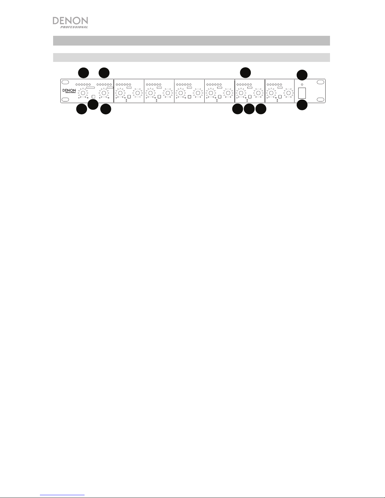
Front Panel
1. Main Input Level Control: Use this knob to adjust the level of the Main Input signal.
2. Input Level Meter: This LED meter shows the level of the Main Input signal. If the Clip
LED illuminates, turn down the Main Input to prevent the signal from distorting.
3. Main Link Control: Press this switch to send the Main Input signal to the Main Output.
4. Main Output Level Control: Use this knob to adjust the level of the Main Output signal.
5. Output Level Meter: This LED meter shows the level of the Main Output signal. If the
Clip LED illuminates, turn down the signal at either the input stage or the Main Output to
avoid distorting the signal.
6. Split/Mix: Use this switch to select the mode for each mono channel. For Splitter mode,
disengage the switch, and the Main Input signal will be split and routed to this channel
output. For Mixer mode, engage this switch, and the mono channel input signal will be
sent to the Main Output bus. This signal will combine with the main input signal when the
Main Link is activated. You can also route the mono channel input signal to the mono
channel output directly.
7. Channel Level Control: Use this knob to adjust the level of each mono channel. In
Splitter mode, this adjusts the output level of each individual mono channel. When in
Mixer mode, this adjusts how much of the mono channel input signal is sent to the Main
Output and/or each individual mono channel output.
8. Input/Output Level Meter: This LED meter shows the output level of each mono
channel. If the Clip LED illuminates, turn down the Main Input Level Control to prevent the
signal from distorting.
9. Balance/Pan Control: If the stereo main signal is split into the mono channel output, or
the mono input signal is routed to the stereo main output bus, use this knob to determine
the proportion between the left and the right channel.
10. Power Switch: Use this switch to turn the unit on or off.
11. Power LED: This LED will light up when the unit is powered on.
INPUT LEVEL OUTPUT LEVEL IN/ OUT LEVEL IN/OUT LEVEL IN/ OUT LEVEL IN/OUT LEVEL IN /OUT LEVEL IN/OUT LEVEL
ON
POWER
OFF
-18-12-6+
120 CLIP-18-12-6+120CLIP-18-12-6+120 CLIP
-18-12-6+
120 CLIP
-18-12-6+
120 CLIP
-18-12-6+
120 CLIP
-18-12-6+
120 CLIP
-18-12-6+
120CLIP
(dB)(dB) (dB) (dB) (dB) (dB) (dB) (dB)
SPLITTER
MIXER
SPLITTER
MIXER
SPLITTER
MIXER
SPLITTER
MIXER
SPLITTER
MIXER
SPLITTER
MIXER
LR LR LR LR LR LR
MAIN
LINK
0
0
0
000
MAIN IN MAIN OUT LEVEL
CH 1 CH 2 CH 3 CH 4 CH 5 CH 6
LEVEL LEVEL LEVEL LEVEL LEVEL
BAL/PAN BAL/PAN BAL/PAN BAL/PAN BAL/PAN BAL/PAN
SPLIT MIX 6
MIXERSPLITTER
1
2
3
4
5
7 6 9
8
10
10
11
11
Page 4
4
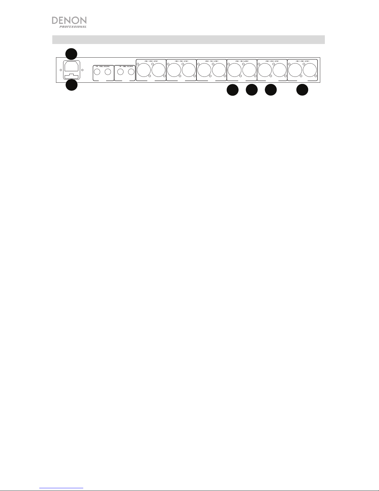
Rear Panel
1. Fuse Holder: Check what the available voltage is in your country and confirm the voltage
switch for Split Mix 6 is configured correctly before connecting the power cable to Split
Mix 6.
Caution: The fuse should only be changed by a qualified technician. If the fuse continues
to blow after replacing, discontinue use of Split Mix 6 until it is repaired.
2. Power Connector: Connect the included power cable here.
Note: Do not connect the power cable to Split Mix 6 until the voltage has been correctly
set.
3. Main Inputs: These two balanced XLR connectors are used to input the main stereo
signal. In Splitter mode, these can be sent to each mono channel output.
4. Main Outputs: These two balanced XLR connectors are used to output the main stereo
signal. By engaging the Main Link switch, the signal will be sent to the Main Input.
5. Mono Channel Inputs: For channels 1-4, use the XLR balanced connectors to input the
mono signal. For channels 5-6, use the TRS connectors.
6. Mono Channel Outputs: For channels 1-4, use the XLR balanced connectors to output
the mono signal. For channels 5-6, use the TRS connectors.
00
CH 4 CH 3 CH 2 CH 1 MAIN OUT MAIN IN
RLRININININ OUTOUTOUTOUTINOUT INOUT L
CH 6 CH 5
AC INPUT: 100-240V~50/60Hz
FUSE: T500mAL AC 250V
RATED POWER CONSUMPTION: 15W
1
2
3
4
5
769
8
10
11
1
2
345
6
Page 5
5
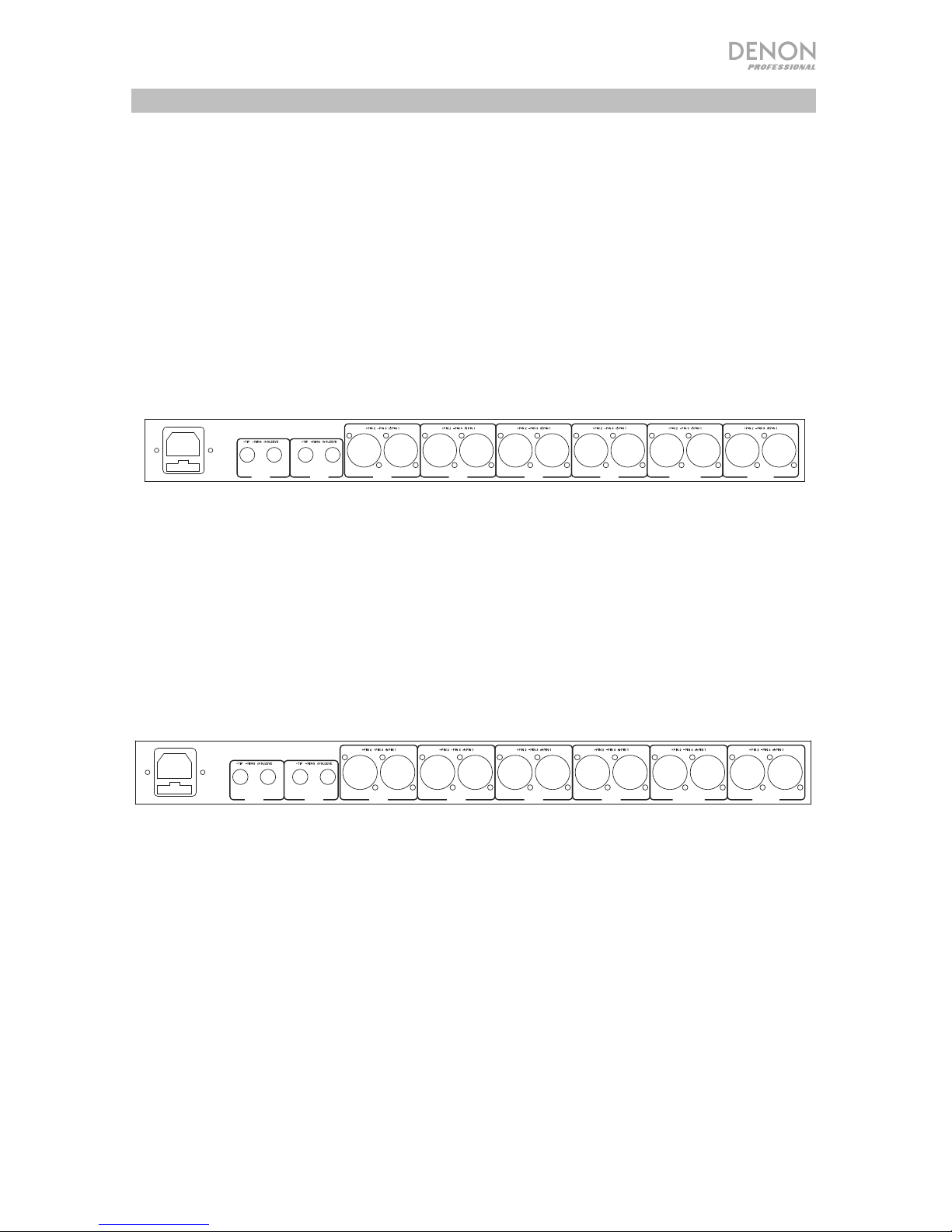
Operation
Using Split Mix 6 as a splitter:
You can split a specific Main Input signal to 6 outputs. With the Main Link switch engaged, 2
further outputs are added.
In this application, use the Split/Mix switch to select the Splitter operational mode for each
mono channel, apply the main signal from the Main Input connectors, and get the 6 outputs
from the Mono Output connectors of each channel. While the Main Link switch is engaged,
the Main Output will also be linked with the Main Input signal, and two further outputs are
provided.
Using Split Mix 6 as a mixer:
Use this application to mix the main stereo signal with several mono signals. Use the Split/Mix
switch to select the mixer operational mode for each mono channel, input the signal from the
mono input of each channel, and output the main mixed signal from the Main Output. While
the Main Link switch is engaged, the Main Input will also be linked with the Main Output
signal, and two further input signals can be mixed with the Main Output signal.
Rack Mounting
For secure mounting, use a universal rack shelf available from various rack manufacturers or
your local musical instrument dealer. Split Mix 6 fits into a standard 19" (483 mm) rack. Please
allow at least an additional 4" (102 mm) depth for the connectors on the rear panel. Be sure
there is enough space around the unit for sufficient ventilation. Do not place Split Mix 6 on
high temperature devices (such as power amplifiers) to avoid overheating.
Mono
Channel
Output
6
Mono
Channel
Output
5
Mono
Channel
Output
4
Mono
Channel
Output
3
Mono
Channel
Output
2
Mono
Channel
Output
1
Main
Output
Main
Input
Mono
Channel
Input
6
Mono
Channel
Input
5
Mono
Channel
Input
4
Mono
Channel
Input
3
Mono
Channel
Input
2
Mono
Channel
Input
1
Main Mixed
Signal
Output
Main Input
Signal
CH 4 CH 3 CH 2 CH 1 MAIN OUT MAIN IN
RLRININININ OUTOUTOUTOUTINOUT INOUT L
CH 6 CH 5
AC INPUT: 100-240V~50/60Hz
FUSE: T500mAL AC 250V
RATED POWER CONSUMPTION: 15W
CH 4 CH 3 CH 2 CH 1 MAIN OUT MAIN IN
RLRININININ OUTOUTOUTOUTINOUT INOUT L
CH 6 CH 5
AC INPUT: 100-240V~50/60Hz
FUSE: T500mAL AC 250V
RATED POWER CONSUMPTION: 15W
Page 6
6
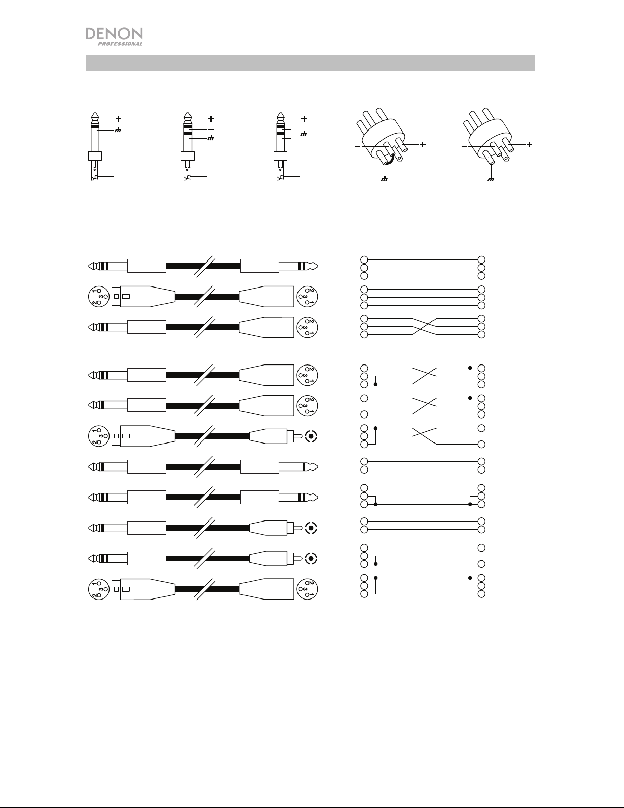
Wire Connections
You can wire your XLR or 1/4” (6.35 mm) TRS cables as balanced or unbalanced.
Here are some examples:
Determine the wiring configuration you need for your application and audio connections:
Tip
Sleeve
Pin 2
Pin 3
Pin 1,
linked to Pin 3
Balanced
Unbalanced
Tip
Ring
Sleeve
Tip
Sleeve
Ring
Pin 1
Tip
Ring
Sleeve
1
2
3
1
2
3
Tip
Ring
Sleeve
1
2
3
Tip
Ring
Sleeve
1
2
3
Tip
Sleeve
1
2
3
1
2
3
Center
Screen
Tip
Sleeve
Tip
Sleeve
Tip
Ring
Sleeve
Tip
Ring
Sleeve
Tip
Sleeve
Center
Screen
Tip
Ring
Sleeve
Center
Screen
1
2
3
1
2
3
Pin 3
Tip
Sleeve
Ring
Pin 2
Page 7

7
Guía del usuario (Español)
Introducción
El divisor/mezclador Split Mix 6 está equipado con las siguientes características:
• Tamaño para 1 rack
• Interruptor de divisor/mezclador para cada canal monoaural
• Divisor de 2 entradas, 6+2 salidas
• 6 controles de balance/pan para cada canal
• Control de nivel de la entrada y la salida principales
• La función de enlace principal permite el encaminamiento de la señal de entrada
principal hacia la salida principal.
• Controles de balance y nivel con medidores LED de 6 segmentos en los canales de
entrada monoaurales
• Conectores XLR y TRS balanceados
• Unidad de voltaje doble para un funcionamiento universal.
Consulte el capítulo Instalación para información acerca de cómo integrar el Split Mix 6 con
su sistema de audio y luego consulte el capítulo Funcionamiento para comenzar a utilizar el
Split Mix 6.
Contenido de la caja
Split Mix 6
Cable de corriente
Guía del usuario
Manual sobre la seguridad y garantía
Soporte
Para obtener la información más reciente acerca de este producto (requisitos de sistema,
información de compatibilidad, etc.) y registrarlo, visite denonpro.com.
Page 8
8
Características
Panel frontal
1. Control de nivel de entrada principal: Use esta perilla para ajustar el nivel de la señal
de entrada principal.
2. Medidor de nivel de entrada: Este medidor LED muestra el nivel de la señal de entrada
principal. Si se enciende el LED de recorte, disminuya la entrada principal para evitar la
distorsión de la señal.
3. Control del enlace principal: Pulse este interruptor para enviar la señal de entrada
principal hacia la salida principal.
4. Control de nivel de la salida principal: Use esta perilla para ajustar el nivel de la señal
de salida principal.
5. Medidor del nivel de salida: Este medidor LED muestra el nivel de la señal de entrada
principal. Si se enciende el LED de recorte, disminuya la señal en la etapa de entrada o
en la salida principal para evitar la distorsión de la señal.
6. División/mezcla: Utilice este interruptor para seleccionar el modo de cada canal
monoaural. En el modo divisor, desactive el interruptor y la señal de entrada principal se
dividirá y encaminará hacia la salida de este canal. En el modo mezclador, active este
interruptor y la señal de entrada del canal monoaural se enviará al bus de la salida
principal. esta señal se combinará con la señal de entrada principal cuando se active el
enlace principal. También puede encaminar la señal de entrada del canal monoaural
hacia la salida del canal monoaural directamente.
7. Control de nivel del canal: Utilice esta perilla para ajustar el nivel de cada canal
monoaural. En el modo divisor, esta perilla ajusta el nivel de salida de cada canal
monoaural individual. En el modo mezclador, esta perilla ajusta la medida en la que la
señal de entrada del canal monoaural se envía a la salida principal y/o a la salida de cada
canal monoaural individual.
8. Medidor del nivel de entrada/salida: Este medidor LED muestra el nivel de salida de
cada canal monoaural. Si se enciende el LED de recorte, disminuya el control de nivel de
la entrada principal para evitar la distorsión de la señal.
9. Control de balance/pan: Si la señal estéreo principal se divide en la salida del canal
monoaural o si la señal de entrada monoaural se encamina hacia el bus de salida estéreo
principal, utilice esta perilla para determinar la proporción entre el canal izquierdo y el
canal derecho.
10. Interruptor de encendido: Utilice este interruptor para encender y apagar la unidad.
11. LED de encendido: Este LED se enciende cuando la unidad está encendida.
INPUT LEVEL OUTPUT LEVEL IN/ OUT LEVEL IN/OUT LEVEL IN/ OUT LEVEL IN/OUT LEVEL IN /OUT LEVEL IN/OUT LEVEL
ON
POWER
OFF
-18-12-6+
120 CLIP-18-12-6+120CLIP-18-12-6+120 CLIP
-18-12-6+
120 CLIP
-18-12-6+
120 CLIP
-18-12-6+
120CLIP-18-12-6+120 CLIP
-18-12-6+
120CLIP
(dB)(dB) (dB) (dB) (dB) (dB) (dB) (dB)
SPLITTER
MIXER
SPLITTER
MIXER
SPLITTER
MIXER
SPLITTER
MIXER
SPLITTER
MIXER
SPLITTER
MIXER
LR LR LR LR LR LR
MAIN
LINK
0
0
0
000
MAIN IN MAIN OUT LEVEL
CH 1 CH 2 CH 3 CH 4 CH 5 CH 6
LEVEL LEVEL LEVEL LEVEL LEVEL
BAL/PAN BAL/PAN BAL/PAN BAL/PAN BAL/PAN BAL/PAN
SPLIT MIX 6
MIXERSPLITTER
1
2
3
4
5
7 6 9
8
10
10
11
11
Page 9

9
Panel trasero
1. Portafusibles: Verifique el voltaje disponible en su país y confirme si el interruptor de
voltaje del Split Mix 6 se encuentra en la posición correcta antes de conectar el cable de
corriente al Split Mix 6.
Precaución: El fusible sólo debe ser reemplazado por un técnico calificado. Si el fusible
vuelve a quemarse después de su reemplazo, suspenda el uso del Split Mix 6 hasta que
sea reparado.
2. Conector de corriente: Conecte aquí el cable de alimentación incluido.
Nota: No conecte el cable de corriente al Split Mix 6 hasta que el voltaje haya sido
ajustado correctamente.
3. Entradas principales: La señal estéreo principal entra por estos dos conectores XLR
balanceados. En el modo divisor, pueden enviarse a cada salida de canal monoaural.
4. Salidas principales: La señal estéreo principal sale por estos dos conectores XLR
balanceados. Al activar el interruptor Main Link, la señal se enviará hacia la salida
principal.
5. Entradas de canal monoaural: Utilice los conectores XLR balanceados para que la
señal monoaural entre a los canales 1-4. Para los canales 5-6, utilice los conectores TRS.
6. Salidas de canal monoaural: Utilice los conectores XLR balanceados para que la señal
monoaural salga por los canales 1-4. Para los canales 5-6, utilice los conectores TRS.
00
CH 4 CH 3 CH 2 CH 1 MAIN OUT MAIN IN
RLRININININ OUTOUTOUTOUTINOUT INOUT L
CH 6 CH 5
AC INPUT: 100-240V~50/60Hz
FUSE: T500mAL AC 250V
RATED POWER CONSUMPTION: 15W
1
2
3
4
5
769
8
10
11
1
2
345
6
Page 10

10
Funcionamiento
Uso del Split Mix 6 como divisor:
Puede dividir una señal de entrada principal específica en 6 salidas. Si se activa el
interruptorMain Link se agregan 2 salidas adicionales.
En esta aplicación, utilice el interruptor Split/Mix para seleccionar el modo de funcionamiento
como divisor para cada canal monoaural, aplique la señal principal proveniente de los
conectores de la entrada principal y obtenga las 6 salidas por los conectores de salida
monoaural de cada canal. Siempre que esté activado el interruptor Main Link, la salida
principal también estará enlazada con la señal de entrada principal y se proveerán dos salidas
adicionales.
Uso del Split Mix 6 como mezclador:
Utilice esta aplicación para mezclar la señal estéreo principal con múltiples señales
monoaurales. Utilice el interruptor Split/Mix para seleccionar el modo de funcionamiento
como mezclador para cada canal monoaural, hacer que la señal entre por la entrada
monoaural de cada canal y que la señal principal salga mezclada por la salida principal.
Siempre que esté activado el interruptor Main Link, la entrada principal también estará
enlazada con la señal de salida principal y se podrán mezclar dos salidas adicionales con la
señal de salida principal.
Montaje en rack
Para un montaje seguro, utilice un estante tipo rack universal de cualquier fabricante o de su
tienda local de instrumentos musicales. El
Split Mix 6 cabe en un rack estándar de 483 mm
(19 pulg.). Deje como mínimo una profundidad adicional de 102 mm (4 pulg.) para los
conectores del panel trasero. Asegúrese de que haya suficiente espacio alrededor de la
unidad para una ventilación adecuada. No coloque el Split Mix 6 sobre dispositivos de alta
temperatura (tales como amplificadores de potencia) para evitar su sobrecalentamiento.
Salida de
canal
monoaural
6
Salida de
canal
monoaural
5
Salida de
canal
monoaural
4
Salida de
canal
monoaural
3
Salida de
canal
monoaural
2
Salida de
canal
monoaural
1
Salida
principal
Salidas
Entrada
Entrada de
canal
monoaural
6
Entrada de
canal
monoaural
5
Entrada de
canal
monoaural
4
Entrada de
canal
monoaural
3
Entrada de
canal
monoaural
2
Entrada de
canal
monoaural
1
Salida de la
señal
principal
mezclada
Señal de
entrada
principal
CH 4 CH 3 CH 2 CH 1 MAIN OUT MAIN IN
RLRININININ OUTOUTOUTOUTINOUT INOUT L
CH 6 CH 5
AC INPUT: 100-240V~50/60Hz
FUSE: T500mAL AC 250V
RATED POWER CONSUMPTION: 15W
CH 4 CH 3 CH 2 CH 1 MAIN OUT MAIN IN
RLRININININ OUTOUTOUTOUTINOUT INOUT L
CH 6 CH 5
AC INPUT: 100-240V~50/60Hz
FUSE: T500mAL AC 250V
RATED POWER CONSUMPTION: 15W
Page 11

11
Cableado
Puede cablear sus cables XLR o TRS de 6,35 mm (1/4 pulg.) como balanceados o no
balanceados. Aquí hay algunos ejemplos:
Determine la configuración del cableado necesario para su aplicación y conexiones de audio:
Balanceado
No balanceado
Punta
Nuca
Manguito
Punta
Nuca
Manguito
1
2
3
1
2
3
Punta
Nuca
Manguito
1
2
3
Punta
Nuca
Manguito
1
2
3
Punta
Manguito
1
2
3
1
2
3
Centro
Anillo
Punta
Manguito
Punta
Manguito
Punta
Nuca
Manguito
Punta
Nuca
Manguito
Punta
Manguito
Centro
Anillo
Punta
Nuca
Manguito
Centro
Anillo
1
2
3
1
2
3
Punta
Manguito
Punta
Manguito
Nuca
Punta
Manguito
Nuca
Patilla 2
Patilla 3
Patilla 1,
unida a Patilla 3
Patilla 1
(Patilla 3
Patilla 2
Page 12

12
Guide d’utilisation (Français)
Présentation
Le Split Mix 6 est un séparateur/mélangeur de signaux et dispose des éléments suivants :
• 1U d'espace rack
• Sélecteur séparateur/mélangeur pour chaque canal mono
• 2 entrées, 6+2 sorties séparateur
• Commande d’équilibre/de panoramique pour chaque canal
• Commandes de niveau d’entrée et de sortie général
• Fonction Main Link permet d'acheminer le signal de l'entrée principale à la sortie
principale.
• Commandes d’équilibre et de niveau avec vumètres DEL à 6 segments sur canaux
d’entrée mono
• Connecteurs XLR et TRS symétriques
• Appareil bitension permettant une utilisation partout dans le monde
Veuillez consulter la section Installation de ce guide pour apprendre comment intégrer le Split
Mix 6 à votre système audio, puis reportez-vous à la section Fonctionnement pour
commencer à l’utiliser.
Contenu de la boîte
Split Mix 6
Câble d'alimentation
Guide d'utilisation
Consignes de sécurité et informations concernant la garantie
Assistance technique
Pour les toutes dernières informations concernant la configuration système requise, la
compatibilité et l’enregistrement du produit, veuillez visiter denonpro.com.
Page 13

13
Caractéristiques
Panneau avant
1. Commande du niveau de l'entrée principale : Ce bouton permet d’ajuster le niveau du
signal d’entrée principal.
2. Vumètre du niveau d’entrée : Ce vumètre DEL indique le niveau du signal d'entrée
principal. Si la DEL s’allume, diminuez le niveau de l’entrée principale afin d’éviter
l’écrêtement du signal.
3. Main Link : Cette touche permet d'acheminer le signal de l'entrée principale à la sortie
principale.
4. Commande du niveau de la sortie principale : Ce bouton permet d’ajuster le niveau du
signal de sortie principal.
5. Vumètres du niveau de sortie : Ce vumètre DEL indique le niveau du signal de sortie
principal. Si la DEL s’allume, diminuez soit le niveau de l’entrée principale ou de la sortie
principale afin d’éviter l’écrêtement du signal.
6. Split/Mix : Cette touche permet de choisir le mode de fonctionnement de chaque canal
mono. Pour le mode séparateur, relâchez la touche, et le signal d'entrée principal sera
séparé et acheminé à la sortie de ce canal. Pour le mode mélangeur, enfoncez la touche,
et le signal d'entrée du canal mono sera acheminé à la sortie principale. Ce signal est
combiné avec le signal de l'entrée principale lorsque la touche Main Link est enfoncée.
Vous pouvez également acheminer directement le signal d'entrée du canal mono à la
sortie du canal mono.
7. Commande de niveau du canal : Ce bouton permet d’ajuster le niveau de chaque canal
mono. En mode séparateur, ce bouton permet de régler le niveau de sortie du canal
mono individuel. En mode mélangeur, ce bouton permet de régler la quantité de signaux
d'entrée du canal mono sera acheminé à la sortie principale et/ou à la sortie de chaque
canal mono.
8. Vumètres du niveau d’entrée/de sortie : Ce vumètre DEL indique le niveau de sortie de
chaque canal mono. Si la DEL s’allume, diminuez le niveau de l’entrée principale afin
d’éviter l’écrêtement du signal.
9. Commande d’équilibre/de panoramique : Si le signal stéréo principal est séparé et
acheminé à la sortie du canal mono, ou si le signal d'entrée mono est acheminé vers la
sortie stéréo principale, ce bouton permet de déterminer la proportion du signal entre le
canal gauche et le canal droit.
10. Interrupteur d'alimentation : Cet interrupteur permet de mettre l'appareil sous et hors
tension.
11. DEL d'alimentation : Cette DEL s'allume lorsque l’appareil est sous tension.
INPUT LEVEL OUTPUT LEVEL IN/ OUT LEVEL IN/OUT LEVEL IN/ OUT LEVEL IN/OUT LEVEL IN /OUT LEVEL IN/OUT LEVEL
ON
POWER
OFF
-18-12-6+
120 CLIP-18-12-6+120CLIP-18-12-6+120 CLIP
-18-12-6+
120 CLIP
-18-12-6+
120CLIP-18-12-6+120 CLIP
-18-12-6+
120CLIP-18-12-6+120CLIP
(dB)(dB) (dB) (dB) (dB) (dB) (dB) (dB)
SPLITTER
MIXER
SPLITTER
MIXER
SPLITTER
MIXER
SPLITTER
MIXER
SPLITTER
MIXER
SPLITTER
MIXER
LR LR LR LR LR LR
MAIN
LINK
0
0
0
000
MAIN IN MAIN OUT LEVEL
CH 1 CH 2 CH 3 CH 4 CH 5 CH 6
LEVEL LEVEL LEVEL LEVEL LEVEL
BAL/PAN BAL/PAN BAL/PAN BAL/PAN BAL/PAN BAL/PAN
SPLIT MIX 6
MIXERSPLITTER
1
2
3
4
5
7 6 9
8
10
10
11
11
Page 14

14
Panneau arrière
1. Compartiment de fusible : Vérifiez la tension secteur pour votre région et assurez-vous
que le sélecteur de tension d'entrée du Split Mix 6 est réglé correctement avant de
brancher le câble d’alimentation et de mettre l’appareil sous tension.
Mise en garde : Le fusible ne doit être remplacé que par un technicien qualifié. Si le
fusible continue de sauter après avoir été remplacé, cessez d'utiliser l’appareil et faites-le
inspecter par un technicien.
2. Entrée d'alimentation : Cette entrée permet de brancher le câble d’alimentation fourni.
Remarque : Ne pas brancher le câble d’alimentation secteur du Split Mix 6 avant d’avoir
correctement réglé la tension.
3. Entrées principales : Ces deux connecteurs symétriques XLR permettent l’entrée du
signal stéréo principal. En mode séparateur, celles-ci peuvent être acheminées à la sortie
de chaque canal mono.
4. Sorties principales : Ces deux connecteurs symétriques XLR permettent la sortie du
signal stéréo principal. En enfonçant la touche Main Link, le signal sera acheminé à
l’entrée principale.
5. Entrées des canaux mono : Pour les canaux 1-4, utiliser les connecteurs XLR
symétriques pour acheminer le signal mono à l’entrée. Pour les canaux 5-6, utiliser les
connecteurs TRS.
6. Sorties des canaux mono : Pour les canaux 1-4, utiliser les connecteurs XLR
symétriques pour acheminer le signal mono à la sortie. Pour les canaux 5-6, utiliser les
connecteurs TRS.
00
CH 4 CH 3 CH 2 CH 1 MAIN OUT MAIN IN
RLRININININ OUTOUTOUTOUTINOUT INOUT L
CH 6 CH 5
AC INPUT: 100-240V~50/60Hz
FUSE: T500mAL AC 250V
RATED POWER CONSUMPTION: 15W
1
2
3
4
5
769
8
10
11
1
2
345
6
Page 15

15
Fonctionnement
Utilisation du Split Mix 6 comme séparateur de signaux :
Vous pouvez séparer un signal d'entrée principal vers 6 sorties. Lorsque la touche Main Link
est enfoncée, vous obtenez 2 sorties supplémentaires.
Pour cette application, utilisez la touche Split/Mix afin de sélectionner le mode séparateur
pour chaque canal mono, appliquez le signal principal des connecteurs de l'entrée principale
et obtenez les 6 sorties des connecteurs de sortie mono de chaque canal. Lorsque la touche
Main Link est enfoncée, le signal de la sortie principale sera aussi combiné avec le signal de
l’entrée principale, et deux sorties supplémentaires sont fournies.
Utilisation du Split Mix 6 comme mélangeur :
Utilisez cette application pour mélanger le signal stéréo principal avec plusieurs signaux
mono. Utilisez la touche Split/Mix afin de sélectionner le mode mélangeur pour chaque canal
mono, acheminez le signal entant de l’entrée mono de chaque canal et acheminez le signal
principal combiné sortant de la sortie principale. Lorsque la touche Main Link est enfoncée, le
signal de l’entrée principale sera aussi mixé avec le signal de la sortie principale, et deux
signaux d’entrées supplémentaires peuvent être mixés avec le signal de la sortie principale.
Montage sur rack
Pour un montage sûr, utilisez un des racks standard offerts par les différents fabricants et
disponibles chez votre marchand local. Le Split Mix 6 se fixe dans un rack standard de
483 mm. Veuillez prévoir au moins 102 mm de profondeur supplémentaires afin
d’accommoder le câblage du panneau arrière. Assurez-vous qu’il y a suffisamment d’espace
libre autour de l’appareil pour une ventilation adéquate et veuillez ne pas installer le Split Mix 6
sur d’autres appareils qui pourraient dégager de la chaleur comme des amplificateurs de
puissance afin d’éviter la surchauffe.
Sortie de
canal mono
6
Sortie de
canal mono
5
Sortie de
canal mono
4
Sortie de
canal mono
3
Sortie de
canal mono
2
Sortie de
canal mono
1
Sortie
principale
Entrée
principale
Entrée
de canal
mono
6
Entrée
de canal
mono
5
Entrée
de canal
mono
4
Entrée
de canal
mono
3
Entrée
de canal
mono
2
Entrée
de canal
mono
1
Signal de la
sortie
principale
mixé
Signal de
l’entrée
principale
CH 4 CH 3 CH 2 CH 1 MAIN OUT MAIN IN
RLRININININ OUTOUTOUTOUTINOUT INOUT L
CH 6 CH 5
AC INPUT: 100-240V~50/60Hz
FUSE: T500mAL AC 250V
RATED POWER CONSUMPTION: 15W
CH 4 CH 3 CH 2 CH 1 MAIN OUT MAIN IN
RLRININININ OUTOUTOUTOUTINOUT INOUT L
CH 6 CH 5
AC INPUT: 100-240V~50/60Hz
FUSE: T500mAL AC 250V
RATED POWER CONSUMPTION: 15W
Page 16

16
Connectiques
Vous pouvez brancher vos câbles XLR ou TRS 6,35 mm de manière symétrique ou asymétrique.
Voici quelques exemples :
Déterminez la configuration de câblage dont vous avez besoin selon votre application et
connexions audio :
Pointe
Corps
Broche 3
Broche 1,
connectée à la broche 3
Pointe
Corps
Bague
Pointe
Corps
Bague
Symétrique
Asymétrique
Pointe
Bague
Corps
Pointe
Bague
Corps
1
2
3
1
2
3
Pointe
Bague
Corps
1
2
3
Pointe
Bague
Corps
1
2
3
Pointe
Corps
1
2
3
1
2
3
Centre
Anneau
Pointe
Corps
Pointe
Corps
Pointe
Bague
Corps
Pointe
Bague
Corps
Pointe
Corps
Centre
Anneau
Pointe
Bague
Corps
Centre
Anneau
1
2
3
1
2
3
Broche 3
Broche 2
Broche 1
Broche 2
Page 17

17
Guida per l'uso (Italiano)
Introduzione
Lo splitter/mixer Split Mix 6 è dotato delle seguenti caratteristiche:
• Dimensioni che occupano 1 spazio su rack
• Interruttore Split / Mix per ciascun canale mono
• 2 ingressi, 6+2 uscite splitter
• 6 comandi Balance / Pan per ciascun canale
• Controllo di livello ingresso e uscita main
• La funzione Main Link consente di convogliare il segnale di ingresso Main all'uscita
Main.
• Comandi di bilanciamento e livello con misuratori a LED a 6 segmenti su canali di
ingresso mono
• Connettori bilanciati XLR e TRS
• Unità a doppio voltaggio per un utilizzo mondiale
Si veda il capitolo Setup della presente guida per sapere come integrare lo Split Mix 6 al
proprio impianto audio, quindi fare riferimento al capitolo Operazione per iniziare a utilizzare lo
Split Mix 6.
Contenuti della confezione
Split Mix 6
Cavo di alimentazione
Guida per l'uso
Istruzioni di sicurezza e garanzia
Assistenza
Per le ultime informazioni in merito a questo prodotto (requisiti di sistema, informazioni sulla
compatibilità, ecc.) e per la registrazione del prodotto, recarsi alla pagina denonpro.com.
Page 18

18
Caratteristiche
Pannello anteriore
1. Comandi livello ingresso Main: servirsi di questa manopola per regolare il livello del
segnale di ingresso Main.
2. Misuratore livello di ingresso: questo misuratore a LED mostra il livello del segnale di
ingresso Main. Se il LED Clip si illumina, abbassare l'ingresso principale Main per evitare
la distorsione del segnale.
3. Comando Main Link: premere questo interruttore per inviare il segnale di ingresso Main
all'uscita Main.
4. Comando livello uscita Main: servirsi di questa manopola per regolare il livello del
segnale di uscita Main.
5. Misuratore livello di uscita: questo misuratore a LED mostra il livello del segnale di
uscita Main. Se il LED Clip si illumina, abbassare il segnale a livello di ingresso o a livello
di uscita Main per evitare la distorsione del segnale.
6. Split/Mix: servirsi di questo interruttore per selezionare la modalità per ciascun canale
mono. Per utilizzare la modalità Splitter, disattivare l'interruttore e il segnale di ingresso
Main sarà suddiviso e convogliato all'uscita di questo canale. Per la modalità Mixer,
attivare l'interruttore e il segnale di ingresso del canale mono sarà inviato alla bus di
uscita Main. Questo segnale si combinerà con il segnale di ingresso main quando il Link
Main è attivato. Si può inoltre convogliare il segnale di ingresso del canale mono
direttamente all'uscita di canale mono.
7. Comando livello canale: servirsi di questa manopola per regolare il livello di ciascun
canale mono. In modalità Splitter, questa regola il livello di uscita di ciascun singolo
canale mono. Quando ci si trova in modalità Mixer, questa regola la quantità di segnale di
ingresso mono inviata all'uscita Main e/o a ciascuna singola uscita di canale mono.
8. Misuratore livello di ingresso/uscita: questo misuratore a LED mostra il livello di uscita
di ciascun canale mono. Se il LED Clip si illumina, abbassare il comando di livello
dell'ingresso principale Main per evitare la distorsione del segnale.
9. Comando Balance/Pan: se il segnale main stereo è suddiviso nell'uscita di canale mono
o se il segnale di ingresso mono è convogliato alla bus di uscita main stereo, servirsi di
questa manopola per stabilire la proporzione tra il canale di sinistra e quello di destra.
10. Interruttore di alimentazione: servirsi di questo interruttore per accendere o spegnere
l'apparecchio.
11. LED di alimentazione: questo LED si illumina quando l'apparecchio viene acceso.
INPUT LEVEL OUTPUT LEVEL IN/ OUT LEVEL IN/OUT LEVEL IN/ OUT LEVEL IN/OUT LEVEL IN /OUT LEVEL IN/OUT LEVEL
ON
POWER
OFF
-18-12-6+
120 CLIP-18-12-6+120 CLIP-18-12-6+120 CLIP
-18-12-6+
120 CLIP
-18-12-6+
120 CLIP
-18-12-6+
120 CLIP
-18-12-6+
120 CLIP
-18-12-6+
120 CLIP
(dB)(dB) (dB) (dB) (dB) (dB) (dB) (dB)
SPLITTER
MIXER
SPLITTER
MIXER
SPLITTER
MIXER
SPLITTER
MIXER
SPLITTER
MIXER
SPLITTER
MIXER
LR LR LR LR LR LR
MAIN
LINK
0
0
0
000
MAIN IN MAIN OUT LEVEL
CH 1 CH 2 CH 3 CH 4 CH 5 CH 6
LEVEL LEVEL LEVEL LEVEL LEVEL
BAL/PAN BAL/PAN BAL/PAN BAL/PAN BAL/PAN BAL/PAN
SPLIT MIX 6
MIXERSPLITTER
1
2
3
4
5
7 6 9
8
10
10
11
11
Page 19

19
Pannello posteriore
1. Portafusi: verificare la tensione disponibile nel proprio Paese e assicurarsi che l'apposito
interruttore dello Split Mix 6 sia posizionato correttamente prima di collegare il cavo di
alimentazione allo Split Mix 6.
Attenzione! Il fusibile deve essere sostituito unicamente da un tecnico qualificato. Se il
fusibile continua a saltare dopo la sostituzione, interrompere l'uso dello Split Mix 6 fino a
quando non viene riparato.
2. Connettore di alimentazione: collegare a questo livello il cavo di alimentazione in
dotazione.
Nota bene: non collegare il cavo di alimentazione allo Split Mix 6 fino a quando la
tensione non è stata impostata correttamente.
3. Ingressi Main: questi due connettori XLR bilanciati sono utilizzati per far entrare il
segnale stereo main. In modalità Splitter, questi possono essere inviati a ciascuna uscita
di canale mono.
4. Uscite Main: questi due connettori XLR bilanciati sono utilizzati per far uscire il segnale
stereo main. Attivando l'interruttore MainLink, il segnale sarà inviato all'ingresso Main.
5. Ingressi canale mono: per i canali 1-4, servirsi dei connettori XLR bilanciati per
l'ingresso del segnale mono. Per i canali 5-6, servirsi dei connettori TRS.
6. Uscite canale mono: per i canali 1-4, servirsi dei connettori XLR bilanciati per l'uscita del
segnale mono. Per i canali 5-6, servirsi dei connettori TRS.
00
CH 4 CH 3 CH 2 CH 1 MAIN OUT MAIN IN
RLRININININ OUTOUTOUTOUTINOUT INOUT L
CH 6 CH 5
AC INPUT: 100-240V~50/60Hz
FUSE: T500mAL AC 250V
RATED POWER CONSUMPTION: 15W
1
2
3
4
5
769
8
10
11
1
2
345
6
Page 20

20
Operazione
Utilizzo dello Split Mix 6 come splitter:
È possibile suddividere un segnale di ingresso main in 6 uscite. Con l'interruttore Main Link
attivo, vengono aggiunte 2 ulteriori uscite.
In questa applicazione, servirsi dell'interruttore Split/Mix per selezionare la modalità operativa
Splitter per ciascun canale mono, applicare il segnale main proveniente dai connettori di
ingresso main e ottenere le 6 uscite dai connettori di uscita mono di ciascun canale. Quando
l'interruttore Main Link è attivo, l'uscita main sarà a sua volta collegata con il segnale di
ingresso main e sono fornite due ulteriori uscite.
Utilizzo dello Split Mix 6 come mixer:
Servirsi di questa applicazione per mixare il segnale stereo main con diversi segnali mono.
Servirsi dell'interruttore Split/Mix per selezionare la modalità operativa del mixer per ciascun
canale mono, inviare il segnale in ingresso dall'ingresso mono di ciascun canale e inviare il
segnale mixato in uscita dall'uscita Main. Quando l'interruttore Main Link è attivo, l'ingresso
main sarà a sua volta collegato con il segnale di uscita main e due ulteriori segnali di ingresso
possono essere mixati con il segnale di uscita main.
Installazione su rack
Per un'installazione sicura servirsi di uno scaffale rack universale disponibile presso numerosi
produttori di rack o presso il vostro rivenditore locale di strumenti musicali. Split Mix 6 si
adatta in un rack standard da 19" (483 mm). Lasciare almeno ulteriori 4" (102 mm) di
profondità per i connettori a livello del pannello posteriore. Assicurarsi che intorno
all'apparecchio vi sia spazio a sufficienza per garantirne un'adeguata ventilazione. Non
collocare lo Split Mix 6 su dispositivi ad alte temperature (ad esempio amplificatori) per evitare
il surriscaldamento.
Uscita
canale
mono
6
Uscita
canale
mono
5
Uscita
canale
mono
4
Uscita
canale
mono
3
Uscita
canale
mono
2
Uscita
canale
mono
1
Uscita Main
Ingresso
Main
Ingresso
canale
mono
6
Ingresso
canale
mono
5
Ingresso
canale
mono
4
Ingresso
canale
mono
3
Ingresso
canale
mono
2
Ingresso
canale
mono
1
Uscita
segnale
main
mixato
Segnale di
ingresso
main
CH 4 CH 3 CH 2 CH 1 MAIN OUT MAIN IN
RLRININININ OUTOUTOUTOUTINOUT INOUT L
CH 6 CH 5
AC INPUT: 100-240V~50/60Hz
FUSE: T500mAL AC 250V
RATED POWER CONSUMPTION: 15W
CH 4 CH 3 CH 2 CH 1 MAIN OUT MAIN IN
RLRININININ OUTOUTOUTOUTINOUT INOUT L
CH 6 CH 5
AC INPUT: 100-240V~50/60Hz
FUSE: T500mAL AC 250V
RATED POWER CONSUMPTION: 15W
Page 21

21
Collegamenti cablati
Si possono cablare i fili XLR o TRS da 6,35 mm (1/4”) come bilanciati o non bilanciati. Ecco
alcuni esempi:
Stabilire la configurazione di cablaggio necessaria per le proprie applicazioni e i propri
collegamenti audio:
Punta
Manica
Poli 2
Poli 3
Poli 1,
collegato a Poli 3
Bilanciato
Non bilanciato
Punta
Anello
Manica
Punta
Manica
Anello
Poli 1
Punta
Anello
Manica
1
2
3
1
2
3
Punta
Anello
Manica
1
2
3
Punta
Anello
Manica
1
2
3
Punta
Manica
1
2
3
1
2
3
Centro
Anello
Punta
Manica
Punta
Manica
Punta
Anello
Manica
Punta
Anello
Manica
Punta
Manica
Centro
Anello
Punta
Anello
Manica
Centro
Anello
1
2
3
1
2
3
Poli 3
Punta
Manica
Anello
Poli 2
Page 22

22
Benutzerhandbuch (Deutsch)
Einführung
Der Split Mix 6 Splitter/Mixer ist mit folgenden Funktionen ausgestattet:
• 1 Rack-Einheit groß
• Split / Mix-Schalter für jeden Monokanal
• 2 Eingangs-, 6+2 Ausgangs-Splitter
• 6 Balance- / Pan-Regler für jeden Kanal
• Haupteingang und Ausgangspegelregler
• Mit der Haupt-Link-Funktion kann das Haupteingangssignal an den Hauptausgang
gesendet werden.
• Balance- und Pegelregler mit 6-teiligen LED-Anzeigen für Mono-Eingangskanäle
• Symmetrische XLR- und Klinkenanschlüsse
• Zweispannungsbetrieb für den weltweiten Einsatz
Bitte lesen Sie das Setup-Kapitel in dieser Anleitung, um zu erfahren, wie Sie Split Mix 6 in Ihr
Audiosystem integrieren können. Lesen Sie anschließend das Kapitel Betrieb, um Split Mix 6
in Betrieb zu nehmen.
Lieferumfang
Split Mix 6
Stromkabel
Benutzerhandbuch
Sicherheitshinweise und Garantieinformationen
Kundendienst
Für die neuesten Informationen zu diesem Produkt (Systemanforderungen, Informationen zur
Kompatibilität etc.) und für die Produktregistrierung besuchen Sie denonpro.com.
Page 23

23
Funktionen
Vorderseite
1. Haupteingangspegelregler: Mit diesem Regler stellen Sie den Pegel des
Haupteingangssignals ein.
2. Eingangspegelanzeige: Diese LED-Anzeige zeigt den Pegel des Haupteingangssignals.
Wenn die Clip-LED leuchtet, reduzieren Sie den Haupteingangspegel, damit das Signal
nicht verzerrt.
3. Haupt-Link-Regler: Betätigen Sie diesen Schalter, um das Haupteingangssignal an den
Hauptausgang zu senden.
4. Hauptausgangspegelregler: Mit diesem Regler stellen Sie den Pegel des
Hauptausgangssignals ein.
5. Ausgangspegelanzeige: Diese LED-Anzeige zeigt den Pegel des Hauptausgangssignals.
Wenn die Clip-LED leuchtet, reduzieren Sie das Signal entweder an der Eingangsstufe
oder am Hauptausgang, um ein verzerrtes Signal zu vermeiden.
6. Split/Mix: Verwenden Sie diesen Schalter, um den Modus für den jeweiligen Monokanal
zu wählen. Für den Splitter-Modus lösen Sie den Schalter und das Haupteingangssignal
wird aufgeteilt und an den Ausgang dieses Kanals weitergeleitet. Für den Mixer-Modus
betätigen Sie diesen Schalter und das Monokanal-Eingangssignal wird an den
Hauptausgangsbus gesendet. Dieses Signal wird mit dem Haupteingangssignal
kombiniert, wenn der Haupt-Link aktiviert ist. Sie können das Mono-Kanaleingangssignal
auch direkt an den Mono-Kanalausgang senden.
7. Kanal-Pegelregler: Mit diesem Regler stellen Sie den Pegel jedes Monokanals ein. In
Splitter-Modus passt dies den Ausgangspegel jedes einzelnen Monokanals an. Im MixerModus kann so eingestellt werden, welcher Anteil des Monokanal-Eingangssignals an
den Hauptausgang und/oder jeden einzelnen Monokanal-Ausgang gesendet wird.
8. Eingangs-/Ausgangspegelanzeige: Diese LED-Anzeige zeigt den Ausgangspegel jedes
Mono-Kanals. Wenn die Clip-LED leuchtet, reduzieren Sie den Haupteingangspegel,
damit das Signal nicht verzerrt.
9. Balance/Pan-Steuerung: Wenn das Stereo-Hauptsignal auf den Mono-Kanalausgang
aufgeteilt wird oder das Mono-Eingangssignal an den Stereo-Hauptausgangsbus geleitet
wird, verwenden Sie diesen Regler, um das Verhältnis zwischen dem linken und dem
rechten Kanal einzustellen.
10. Netzschalter: Verwenden Sie diesen Schalter, um das Gerät ein- oder auszuschalten.
11. Power-LED: Diese LED leuchtet, wenn das Gerät eingeschaltet ist.
INPUT LEVEL OUTPUT LEVEL IN/ OUT LEVEL IN/OUT LEVEL IN/ OUT LEVEL IN/OUT LEVEL IN /OUT LEVEL IN/OUT LEVEL
ON
POWER
OFF
-18-12-6+
120 CLIP-18-12-6+120CLIP-18-12-6+120 CLIP
-18-12-6+
120 CLIP
-18-12-6+
120 CLIP
-18-12-6+
120CLIP-18-12-6+120 CLIP
-18-12-6+
120CLIP
(dB)(dB) (dB) (dB) (dB) (dB) (dB) (dB)
SPLITTER
MIXER
SPLITTER
MIXER
SPLITTER
MIXER
SPLITTER
MIXER
SPLITTER
MIXER
SPLITTER
MIXER
LR LR LR LR LR LR
MAIN
LINK
0
0
0
000
MAIN IN MAIN OUT LEVEL
CH 1 CH 2 CH 3 CH 4 CH 5 CH 6
LEVEL LEVEL LEVEL LEVEL LEVEL
BAL/PAN BAL/PAN BAL/PAN BAL/PAN BAL/PAN BAL/PAN
SPLIT MIX 6
MIXERSPLITTER
1
2
3
4
5
7 6 9
8
10
10
11
11
Page 24

24
Rückseite
1. Sicherungshalter: Überprüfen Sie, welche Spannung in Ihrem Land verfügbar ist und
vergewissern Sie sich, dass der Spannungsschalter für das Split Mix 6 korrekt eingestellt
ist, bevor Sie das Netzkabel mit dem Split Mix 6 verbinden.
Achtung: Die Sicherung darf nur von einem qualifizierten Techniker gewechselt werden.
Wenn die Sicherung nach dem Austausch durchbrennt, stellen Sie die Verwendung des
Split Mix 6 ein, bis das Gerät repariert ist.
2. Stromanschluss: Schließen Sie das mitgelieferte Netzkabel hier an.
Hinweis: Verbinden Sie das Netzkabel erst dann mit dem Split Mix 6, wenn die
Spannung korrekt eingestellt ist.
3. Haupteingänge: Diese beiden symmetrischen XLR-Anschlüsse werden für die Eingabe
des Hauptstereosignals verwendet. Im Splitter-Modus können diese an jeden MonoKanalausgang gesendet werden.
4. Hauptausgänge: Diese beiden symmetrischen XLR-Anschlüsse werden für die Ausgabe
des Hauptstereosignals verwendet. Durch die Aktivierung des Haupt-Link-Schalters wird
das Signal an den Haupteingang gesendet.
5. Mono-Kanaleingänge: Für die Kanäle 1-4 verwenden Sie die symmetrischen XLRAnschlüsse als Eingabe des Mono-Signals. Verwenden Sie die TRS-Anschlüsse für die
Kanäle 5-6.
6. Mono-Kanalausgänge: Verwenden Sie die symmetrischen XLR-Anschlüsse als Ausgabe
des Mono-Signals für die Kanäle 1-4. Verwenden Sie die TRS-Anschlüsse für die Kanäle
5-6.
00
CH 4 CH 3 CH 2 CH 1 MAIN OUT MAIN IN
RLRININININ OUTOUTOUTOUTINOUT INOUT L
CH 6 CH 5
AC INPUT: 100-240V~50/60Hz
FUSE: T500mAL AC 250V
RATED POWER CONSUMPTION: 15W
1
2
3
4
5
769
8
10
11
1
2
345
6
Page 25

25
Betrieb
Verwendung des Split Mix 6 als Splitter:
Sie können ein bestimmtes Haupteingangssignal auf 6 Ausgänge aufteilen. Ist der HauptLink-Schalter aktiviert, werden 2 weitere Ausgänge hinzugefügt.
Bei dieser Anwendung verwenden Sie den Split/Mix-Schalter, um den Splitter-Betriebsmodus
für jeden Mono-Kanal zu wählen, das Hauptsignal der Haupteingangsanschlüsse anzuwenden
und die 6 Ausgänge von den Mono-Ausgangsanschlüssen für jeden Kanal zu erhalten.
Während der Haupt-Link-Schalter aktiviert ist, wird der Hauptausgang auch mit dem
Haupteingangssignal verbunden und zwei weitere Ausgänge verfügbar gemacht.
Verwendung des Split Mix 6 als Mixer:
Nutzen Sie diese Anwendung, um das Hauptstereosignal mit mehreren Monosignalen zu
mischen. Verwenden Sie den Split/Mix-Schalter, um den Mixer-Betriebsmodus für jeden
Mono-Kanal auszuwählen, das Signal aus dem Mono-Eingang jedes Kanals einzugeben und
das Haupt-Mix-Signal aus dem Hauptausgang auszugeben. Wenn der Haupt-Link-Schalter
aktiviert ist, wird auch der Haupteingang mit dem Hauptausgangssignal verknüpft und zwei
weitere Eingangssignale können mit dem Hauptausgangssignal gemischt werden.
Rack-Montage
Für eine sichere Montage, verwenden Sie ein universelles Rack-Regal, das bei verschiedenen
Rack-Herstellern oder bei Ihrem lokalen Musikinstrumentehändler erhältlich ist. Split Mix 6
passt in ein 19" (483mm) Standard-Rack. Bitte kalkulieren Sie zusätzlich mindestens 4" (102
mm) für die Anschlüsse an der Rückseite ein. Sorgen Sie für ausreichend Platz rund um das
Gerät, um eine gute Belüftung zu gewährleisten. Stellen Sie Split Mix 6 niemals auf Geräte, die
hohe Temperaturen abgeben (z.B. Leistungsverstärker), um Überhitzung zu vermeiden.
Mono-
Kanalaus-
gang
6
Mono-
Kanalaus-
gang
5
Mono-
Kanalaus-
gang
4
Mono-
Kanalaus-
gang
3
Mono-
Kanalaus-
gang
2
Mono-
Kanalaus-
gang
1
Hauptausgang
Haupt Eingabe
Mono-
Kanale-
ingang
6
Mono-
Kanale-
ingang
5
Haupt-
Mix-
Signal aus-
gang
Haupt-
Eingang-
signal
CH 4 CH 3 CH 2 CH 1 MAIN OUT MAIN IN
RLRININININ OUTOUTOUTOUTINOUT INOUT L
CH 6 CH 5
AC INPUT: 100-240V~50/60Hz
FUSE: T500mAL AC 250V
RATED POWER CONSUMPTION: 15W
CH 4 CH 3 CH 2 CH 1 MAIN OUT MAIN IN
RLRININININ OUTOUTOUTOUTINOUT INOUT L
CH 6 CH 5
AC INPUT: 100-240V~50/60Hz
FUSE: T500mAL AC 250V
RATED POWER CONSUMPTION: 15W
Mono-
Kanale-
ingang
4
Mono-
Kanale-
ingang
3
Mono-
Kanale-
ingang
2
Mono-
Kanale-
ingang
1
Page 26

26
Kabelverbindungen
Sie können Ihr XLR oder 6,35 mm TRS-Kabel symmetrisch oder unsymmetrisch verdrahten. Hier
sind einige Beispiele:
Bestimmen Sie die Verdrahtungskonfiguration, die Sie für Ihren Einsatz und Ihre Audio-Verbindungen
benötigen:
Spitze
Manschette
Pin 2
Pin 3
Pin 1
mit Pin 3 verbunden
Symmetrisch
Unsymmetrisch
Spitze
Ring
Manschette
Spitze
Manschette
Ring
Pin 1
Spitze
Ring
Manschette
1
2
3
1
2
3
Spitze
Ring
Manschette
1
2
3
Spitze
Ring
Manschette
1
2
3
Spitze
Manschette
1
2
3
1
2
3
Stift
Abschirmung
Spitze
Manschette
Spitze
Manschette
Spitze
Ring
Manschette
Spitze
Ring
Manschette
Spitze
Mansche
tte
Stift
Abschirmung
Spitze
Ring
Manschette
Stift
Abschirmung
1
2
3
1
2
3
Pin 3
Spitze
Manschette
Ring
Pin 2
Page 27

27
Appendix (English)
Technical Specifications
Audio Inputs Connectors
X
LR and 1/4" TRS
Type
RF filtered, servo-balanced input
Impedance
50 kOhms balanced, 25 kOhms unbalanced
Nominal Operating Level
-10 dBV to +4 dBu
Max Input Level
+21 dBu balanced and unbalanced
CMRR
Typ. 40 dB, > 55 dB @ 1 kHz
Audio Outputs Connectors
X
LR and 1/4" TRS
Type
Electronically servo-balanced output stage
Impedance
60 Ohms balanced, 30 Ohms unbalanced
Max Output Level
+22 dBu balanced and unbalanced
Frequency Response
5 Hz–200 kHz, +/-3 dBu
S/N Ratio
>95 dBu, unweighted, 22 Hz –22 kHz
THD
<0.002% typ. @ +4 dBu, 1 kHz, gain 1
Power Supply Voltage
USA/Canada 120V, 60 Hz
U.K./Australia 240 V, 50 Hz
Europe 230 V, 50 Hz
Power Consumption
Max 15 W
Fuse
100 –120 V: T 315 mA H
220 – 240 V: T 200 mA H
Dimensions (length x width x depth)
7.54” x 1.7” x 19”
195 mm x 44 mm x 483 mm
Weight
5.73 lbs.
2.6 kg
Specifications are subject to change without notice.
Trademarks & Licenses
Denon is a trademark of D&M Holdings Inc., registered in the U.S. and other countries.
All other product or company names are trademarks or registered trademarks of their
respective owners.
Page 28

denonpro.com
Manual Version 1.0
 Loading...