

SERVICE MANUAL
For Europe &
Taiwan R.O.C. model
Ver. 1
MODEL
INTEGRATED STEREO AMPLIFIER
PMA-500AE
注 意
サービスをおこなう前に、このサービスマニュアルを
必ずお読みください。本機は、火災、感電、けがなど
に対する安全性を確保するために、さまざまな配慮を
おこなっており、また法的には「電気用品安全法」に
もとづき、所定の許可を得て製造されております。
従ってサービスをおこなう際は、これらの安全性が維
持されるよう、このサービスマニュアルに記載されて
いる注意事項を必ずお守りください。
●
For purposes of improvement, specifications and
design are subject to change without notice.
●
Please use this service manual with referring to the
operating instructions without fail.
●
Some illustrations using in this service manual are
slightly different from the actual set.
Denon Brand Company, D&M Holdings Inc.
●
●
●
●
TOKYO, JAPAN
本機の仕様は性能改良のため、予告なく変更すること
があります。
補修用性能部品の保有期間は、製造打切後8年です。
修理の際は、必ず取扱説明書を参照の上、作業を行っ
てください。
本文中に使用しているイラストは、説明の都合上現物
と多少異なる場合があります。
X0304 V.01 DE/CDM 0608
SAFETY PRECAUTIONS
The following check should be performed for the continued protection of the customer and service technician.
LEAKAGE CURRENT CHECK
Before returning the unit to the customer, make sure you make either (1) a leakage current check or (2) a line to chassis
resistance check. If the leakage current exceeds 0.5 milliamps, or if the resistance from chassis to either side of the power
cord is less than 460 kohms, the unit is defective.
PMA-500AE
CAUTION
Please heed the points listed below during servicing and inspection.
◎ Heed the cautions!
Spots requiring particular attention when servicing, such as
the cabinet, parts, chassis, etc., have cautions indicated on
labels or seals. Be sure to heed these cautions and the cautions indicated in the handling instructions.
◎ Caution concerning electric shock!
(1) An AC voltage is impressed on this set, so touching inter-
nal metal parts when the set is energized could cause
electric shock. Take care to avoid electric shock, by for example using an isolating transformer and gloves when
servicing while the set is energized, unplugging the power
cord when replacing parts, etc.
(2)There are high voltage parts inside. Handle with extra care
when the set is energized.
◎
Caution concerning disassembly and assembly!
Though great care is taken when manufacturing parts from
sheet metal, there may in some rare cases be burrs on the
edges of parts which could cause injury if fingers are moved
across them. Use gloves to protect your hands.
◎ Only use designated parts!
The set's parts have specific safety properties (fire resistance, voltage resistance, etc.). For replacement parts, be
sure to use parts which have the same properties. In particular, for the important safety parts that are marked ! on wiring
diagrams and parts lists, be sure to use the designated parts.
◎ Be sure to mount parts and arrange the
wires as they were originally!
For safety reasons, some parts use tape, tubes or other insulating materials, and some parts are mounted away from the
surface of printed circuit boards. Care is also taken with the
positions of the wires inside and clamps are used to keep
wires away from heating and high voltage parts, so be sure to
set everything back as it was originally.
◎ Inspect for safety after servicing!
Check that all screws, parts and wires removed or disconnected for servicing have been put back in their original positions, inspect that no parts around the area that has been
serviced have been negatively affected, conduct an insulation
check on the external metal connectors and between the
blades of the power plug, and otherwise check that safety is
ensured.
(Insulation check procedure)
Unplug the power cord from the power outlet, disconnect the
antenna, plugs, etc., and turn the power switch on. Using a
500V insulation resistance tester, check that the insulation resistance between the terminals of the power plug and the externally exposed metal parts (antenna terminal, headphones
terminal, microphone terminal, input terminal, etc.) is 1MΩ or
greater. If it is less, the set must be inspected and repaired.
CAUTION
Many of the electric and structural parts used in the set have
special safety properties. In most cases these properties are
difficult to distinguish by sight, and using replacement parts
with higher ratings (rated power and withstand voltage) does
not necessarily guarantee that safety performance will be preserved. Parts with safety properties are indicated as shown
below on the wiring diagrams and parts lists is this service
manual. Be sure to replace them with parts with the designated part number.
(1) Schematic diagrams ... Indicated by the ! mark.
(2) Parts lists ... Indicated by the ! mark.
Concerning important safety parts
Using parts other than the designated parts
could result in electric shock, fires or other
dangerous situations.
注 意
サービス、点検時にはつぎのことにご注意願います。
◎注意事項をお守りください!
サービスのとき特に注意を必要とする個所についてはキャ
ビネット、部品、シャーシなどにラベルや捺印で注意事項を
表示しています。これらの注意書きおよび取扱説明書などの
注意事項を必ずお守りください。
◎感電に注意!
(1) このセットは、交流電圧が印加されていますので通電時
に内部金属部に触れると感電することがあります。従っ
て通電サービス時には、絶縁トランスの使用や手袋の着
用、部品交換には、電源プラグを抜くなどして感電にご
注意ください。
(2) 内部には高電圧の部分がありますので、通電時の取扱に
は十分ご注意ください。
◎分解、組み立て作業時のご注意!
板金部品の端面の『バリ』は、部品製造時に充分管理をして
おりますが、板金端面は鋭利となっている箇所が有りますの
で、部品端面に触れたまま指を動かすとまれに怪我をする場
合がありますので十分注意して作業して下さい。手の保護の
ために手袋を着用してください。
◎指定部品の使用!
セットの部品は難燃性や耐電圧など安全上の特性を持った
ものとなっています。従って交換部品は、使用されていたも
のと同じ特性の部品を使用してください。特に配線図、部品
表に!印で指定されている安全上重要な部品は必ず指定の
ものをご使用ください。
◎部品の取付けや配線の引きまわしは、
元どおりに!
安全上、テープやチューブなどの絶縁材料を使用したり、プ
リント基板から浮かして取付けた部品があります。また内部
配線は引きまわしやクランパーによって発熱部品や高圧部
品に接近しないように配慮されていますので、これらは必ず
元どおりにしてください。
◎サービス後は安全点検を!
サービスのために取り外したねじ、部品、配線などが元どお
りになっているか、またサービスした個所の周辺を劣化させ
てしまったところがないかなどを点検し、外部金属端子部
と、電源プラグの刃の間の絶縁チェックをおこなうなど、安
全性が確保されていることを確認してください。
(絶縁チェックの方法)
電源コンセントから電源プラグを抜き、アンテナやプラグな
どを外し、電源スイッチを入れます。500V 絶縁抵抗計を用
いて、電源プラグのそれぞれの端子と外部露出金属部[アン
テナ端子、ヘッドホン端子マイク端子、入力端子など]との
間で、絶縁抵抗値が1 MΩ 以上であること、この値以下の
ときはセットの点検修理が必要です。
注 意
本機に使用している多くの電気部品、および機構部品は安全
上、特別な特性を持っています。この特性はほとんどの場合、
外観では判別つきにくく、またもとの部品より高い定格(定
格電力、耐圧)を持ったものを使用しても安全性が維持され
るとは、限りません。安全上の特性を持った部品は、この
サービスマニュアルの配線図、部品表につぎのように表示し
ていますので必ず指定されている部品番号のものを使用願
います。
(1) 配線図…
(2) 部品表…
安全上重要な部品について
!マークで表示しています。
!マークで表示しています。
指定された部品と異なるものを使用した場合に
は、感電、火災などの危険を生じる恐れがあり
ます。
2
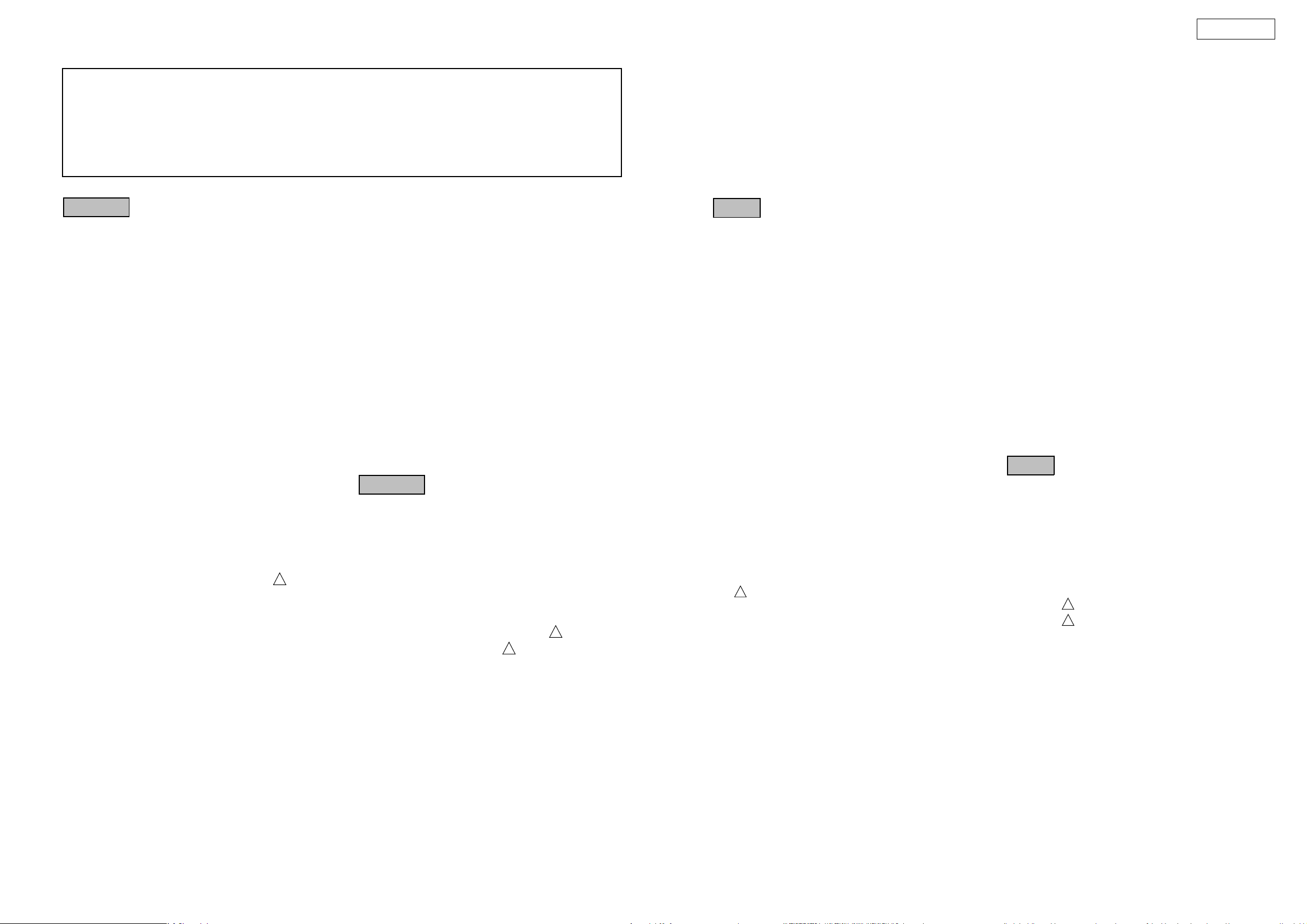
BLOCK AND LEVEL DIAGRAM
PMA-500AE
3
PMA-500AE
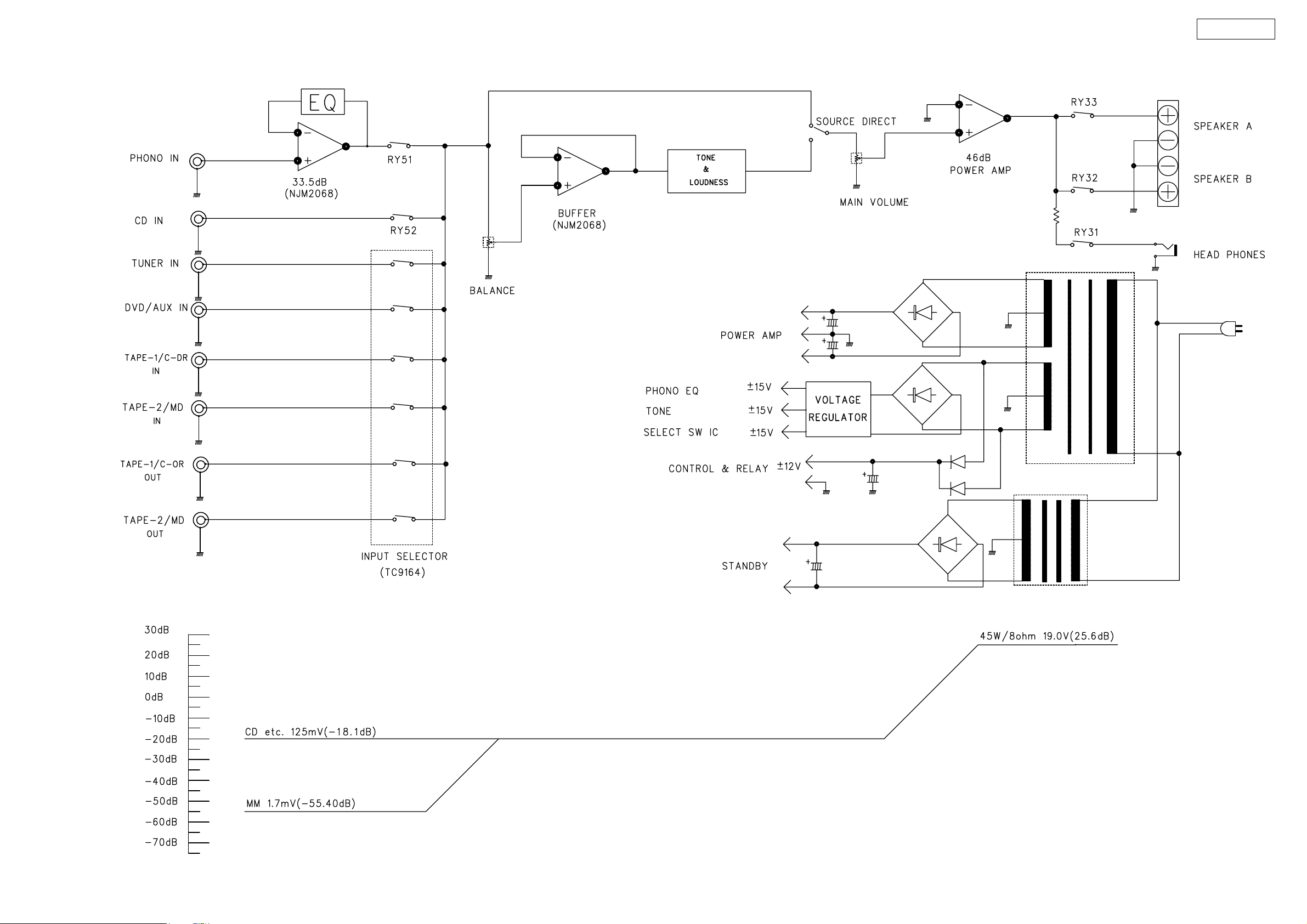
ADJUSTMENT
Idling Current
Required measurement equipment: DC Voltmeter
1. Setup
(1) Place the unit at an ordinary position avoiding direct air
flow from an air-conditioner or fan. Do the adjustment at
a temperature between 15 °C (59 °F) and 30 °C (86 °F).
(2) Set control as follows.
• POWER switch → OFF ( ).
• VOLUME control → fully counterclockwise (
min.)
• SPEAKER terminals → open: do not connect the
speakers, dummy load etc.
2. Adjustment
(1) Remove top cover. And then connect DC Voltmeter to the
test points CN31 and CN32 of CUP11904 Main P.W.B.
(2) Connect power cord to AC wall outlet, and turn POWER
switch "ON" ( ).
(3) Right after power on, adjust VR31 and VR32 so that the
DC voltmeter reads 10 ±1mV.
(4) Then after 2 minutes warm up adjust VR31 and VR32 so
that the DC voltmeter reads 10 ±1mV.
(5) And after 10 minutes warm up adjust VR31 and VR32 so
that the DC voltmeter reads 10 ±0.5mV.
調整
アイドリング電流
調整に必要な測定器 : DCVoltmeter
1. 準備
(1) セットをクーラ、扇風機のそばなど風通しの良い場所
を避け、通常の使用状態に置きます。セットの周囲温
度は、15〜30 ℃で調整をおこないます。
(2) セットのスイッチ類は、次のようにセットします。
・パワースイッチ → OFF( )。
・ボリウム調整つまみ →最小の反時計方向 ( )
にセットします。
・スピーカ端子 →無負荷 ( スピーカを接続し
ません。)
2. 調整
(1) 上カバーをはずし、CUP11904 メイン基板のテストポ
イント (CN31,CN32) に DCVoltmeterを接続します。
(2) 電源コードを AC100V(95〜105Vの範囲でも可)に接
続し、電源スイッチを "ON"( ) にします。
(3) 通電後にテストポイントの電圧が(10 ± 1mV)になる
よう、VR31・VR32 を調整します。
(4) 2分後にテストポイントの電圧が(10 ± 1mV)になる
よう、VR31・VR32 を調整します。
(5) 10 分後にテストポイントの電圧が(10 ± 0.5mV)に
なるよう、VR31・VR32 を調整します。
Power
Trans
DC Voltmeter
CN31
VR31
VR32
CN32
Volume
4
SEMICONDUCTORS
Only major semiconductors are shown, general semiconductors etc. are omitted to list.
主な半導体を記載しています。汎用の半導体は記載を省略しています。
1. IC’s
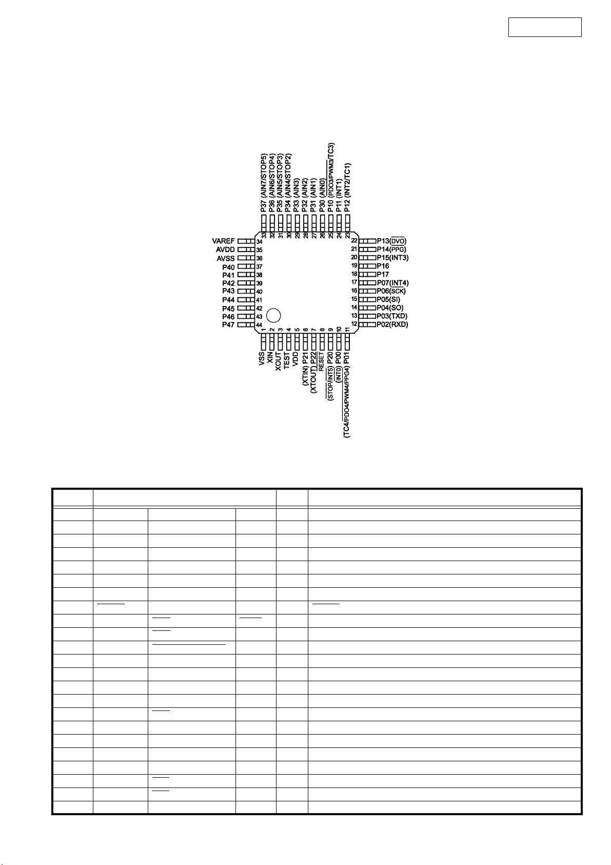
TMP86FH47AUG (IC51)
PMA-500AE
TMP86FH47AUG Terminal Function
Pin No. Port Name I/O Function
1 VSS VSS
2 XIN X IN
3 XOUT X OUT
4 TEST TEST
5VDD VDD
6 P21 XTIN O MUTE/STANDBY LED
7P22 XTOUT O
8 RESET I RESET
9 P20 INT5 STOP I STOP ACT.
10 P00 INT0 I PROTECTOR
11 P01 PDO4/PWM4/PPG4 TC4 O P. DIRECT RELAY
12 P02 RXD I RXD
13 P03 TXD O TXD
14 P04 SO O DATA
15 P05 SI O STROBE
16 P06 SCK O CLK
17 P07 INT4 O S. DIRECT RELAY
18 P17 I P. DIRECT SW
19 P16 I S. DIRECT SW
20 P15 INT3 AC RELAY 1
21 P14 PPG O VOLUME UP
22 P13 DVO O VOLUME DOWN
23 P12 INT2 TC1 I REMOTE IN
5
Pin No. Port Name I/O Function
24 P11 INT1 I POWER OFF
25 P10 PDO3/PWM3 TC3 AC RELAY 2
26 P30 AIN0 AI MODEL
27 P31 AIN1 AI SP A/B
28 P32 AIN2 AI REC. SEL
29 P33 AIN3 AI FUNC. SEL
30 P34 AIN4 STOP2 O H/P MUTE
31 P35 AIN5 STOP3 O SP A
32 P36 AIN6 STOP4 O SP B
33 P37 AIN7 STOP5
34 VAREF Vref
35 AVDD AVDD
36 AVSS AVSS
37 P40 O PHONO
38 P41 O CD
39 P42 O TUNER
40 P43 O AUX-1
41 P44 O AUX-2
42 P45 O AUX-3
43 P46 O TAPE-1
44 P47 O TAPE-2
PMA-500AE
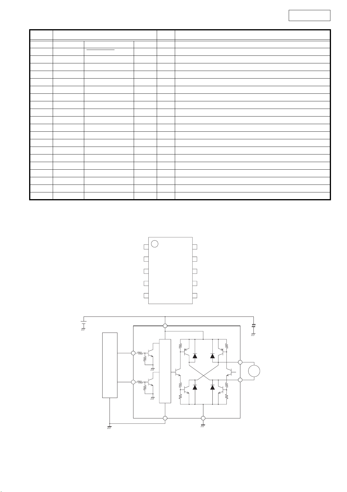
LB1930 (IC52)
CPU
IN1
IN2
V
CC
NC
IN1
IN2
S-GND
60kΩ
3
60kΩ
4
1
2
3
4
5
80kΩ80kΩ
TOP VIEW
LB1930M
V
CC
1
Contorol
block
NC
10
OUT1
9
NC
8
OUT2
7
P-GND
6
C1=1uF
OUT1
9
M
7
OUT2
5 6
S-GND P-GND
6
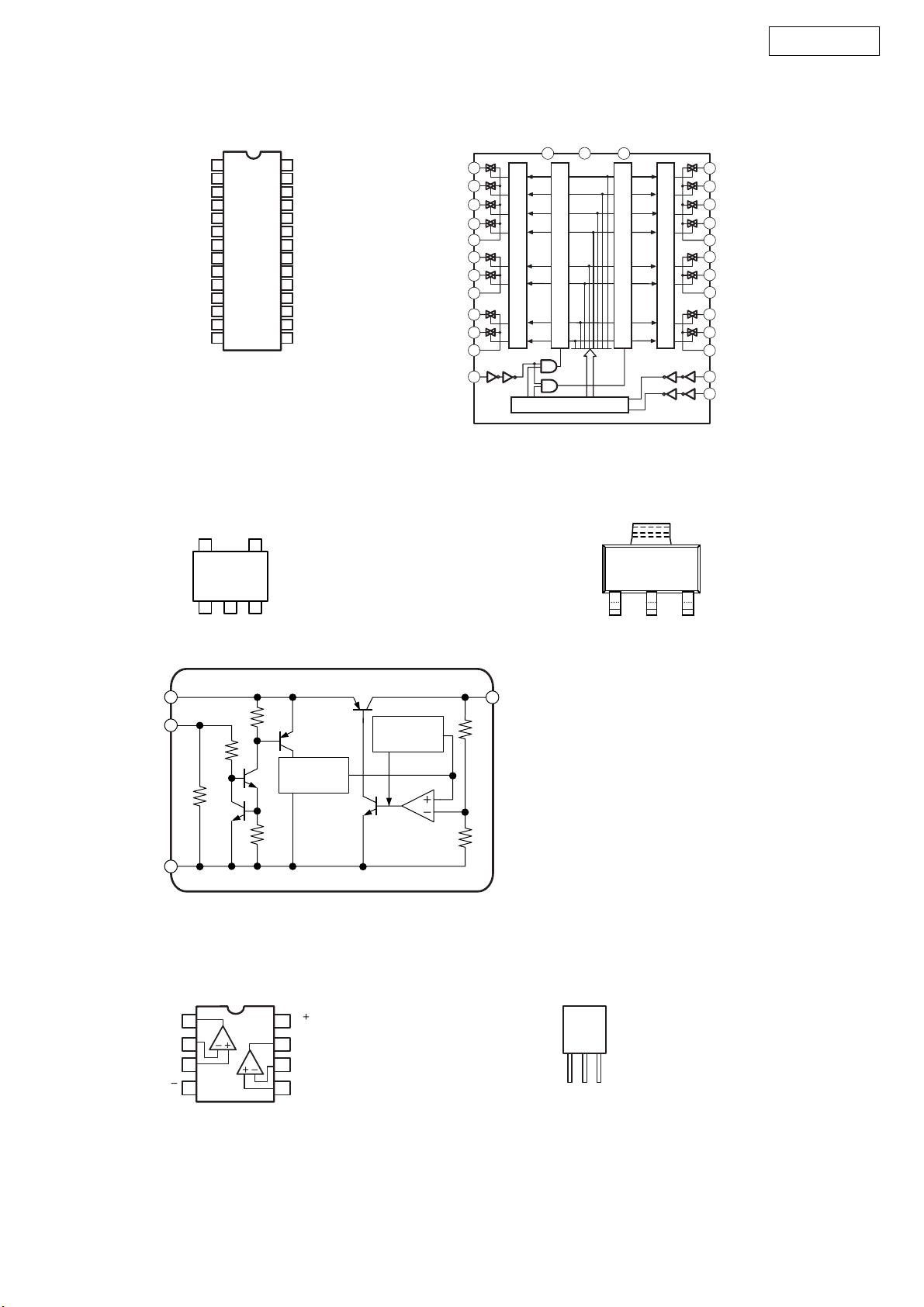
TC9164AN (IC20)
LM1117
SOT-223 PKG (FRONT VIEW)
PMA-500AE
VSS
L-S1
L-S2
L-S3
L-S
L-COM1
L-S5
L-S6
L-COM2
L-S7
L-S8
L-COM3
GND
ST
TC9164AN
1
2
3
4
4
5
6
7
8
9
10
11
12
13
14
28
27
26
25
24
23
22
21
20
19
18
17
16
15
V
DD
R-S1
R-S2
R-S3
R-S4
R-COM1
R-S5
R-S6
R-COM2
R-S7
R-S8
R-COM3
DATA
CK
L-S
L-S
L-S
L-S
L-COM
L-S
L-S
L-COM
L-S
L-S
L-COM
ST
2
1
2
3
4
3
4
5
6
1
5
7
6
8
9
2
10
7
11
8
12
3
13
Level Shifter
GND
V
SS
14
1
Latch Circuit
Shift Register
V
DD
28
Latch Circuit
Level Shifter
NJM2831F (IC81) LM1117S (IC53)
TOP VIEW
45
123
1. CONTROL
2. GND
3. NC
4. V
OUT
5. V
IN
FRONT
VIEW
GND
Vout
Vin
27
26
25
24
23
22
21
20
19
18
17
16
15
R-S
1
R-S
2
R-S
3
R-S
4
R-COM
R-S
5
R-S
6
R-COM
R-S
7
R-S
8
R-COM
DATA
CK
1
2
3
V
IN
Control
GND
NJM2068DD (IC10, 52) NJM7806FA(S) (IC92)
A OUTPUT
A –INPUT
A+INPUT
V
TOP VIEW
1
2
3
4
V
OUT
Thermal
Protection
Bandgap
Reference
KA7812-ABTU (IC91)
V
1
2
B OUTPUT
7
6
B –INPUT
B +INPUT
5
8
FRONT
VIEW
GND
Iutput
Output
7
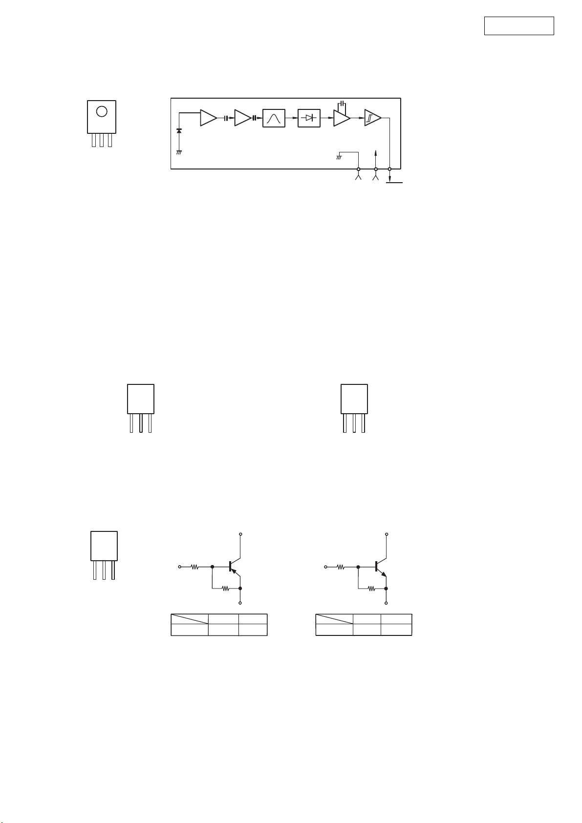
2. REMOTE CONTROL SENSOR
KSM-603TH2A (RC71)
TOP VIEW
PMA-500AE
Vcc
Vout
GND
3. TRANSISTORS
KSA916Y
KSA1175Y
KSC2316Y
KSC2785Y
KSC3198Y
FRONT
VIEW
KTA1024Y
KTA1268GR
KTC3200GR
KTC3206Y
Head
Amp
Limiter
Amp
BPF
Detector &
Comparator
Integrator
Hysteresis
Comparator
GND
2SB1383P
2SD2083P
KTC3114A
FRONT
VIEW
Vcc
Vout
KRA102M
KRC102M
FRONT
VIEW
C
B
E
C
B
E
KRA102M
PNP Type
B
R1
R2
KRA102M
10kohm
10kohm
BCE
KRC102M
NPN Type
R1R1
B
KRC102M 10kohm
CC
R2R2
EE
R1
R2
10kohm
8
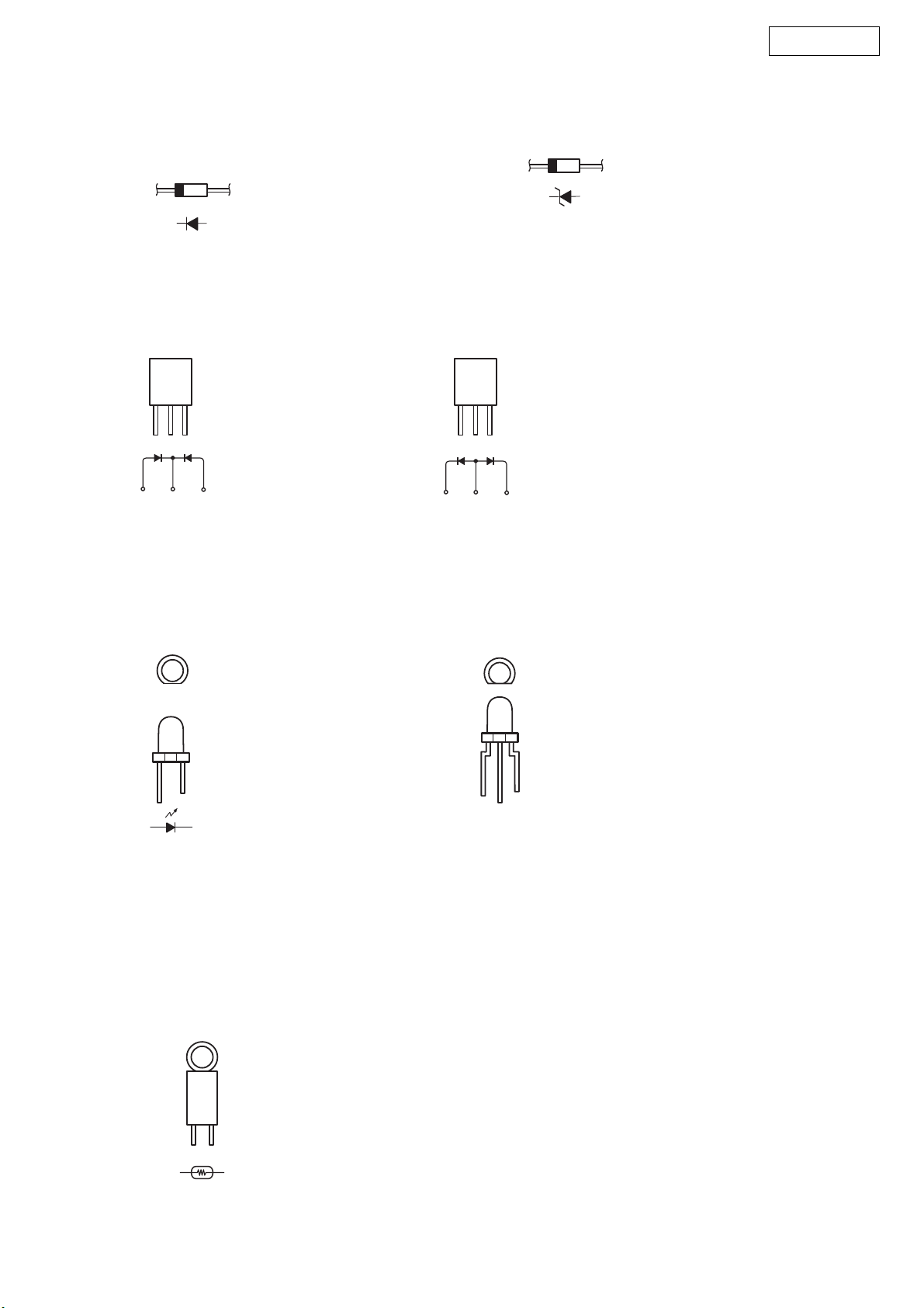
4. DIODES (LED included)
PMA-500AE
1SS133M
1N4003
FMG-22S
FRONT
VIEW
AKA
ZJ4.7B
ZJ7.5B
ZJ15B
ZJ16B
FMG-22R
FRONT
VIEW
AKK
SEL-2915A (Orange)
TOP VIEW TOP VIEW
5. POSISTOR
PTFM04BB222QN34 (TH51)
SML1216W (Red/Green)
CATHODE
RED ANODE
GREEN ANODE
9

PRINTED WIRING BOARDS
MAIN P.W.B. UNIT
PMA-500AE
10
COMPONENT SIDE

PMA-500AE
11
FOIL SIDE

FRONT P.W.B. UNIT
PMA-500AE
12
COMPONENT SIDE

PMA-500AE
NOTE FOR PARTS LIST
• Part indicated with the mark "nsp" are not always in stock and possibly to
take a long period of time for supplying, or in some case supplying of part
may be refused.
• When ordering of part, clearly indicate "1" and "I" (i) to avoid mis-
supplying.
• Ordering part without stating its part number can not be supplied.
• Part indicated with the mark " ★ " is not illustrated in the exploded view.
• Not including General-purpose Carbon Film Resistor in the P.W.Board
parts list. (Refer to the Schematic Diagram for those parts.)
• Not including General-purpose Carbon Chip Resistor in the P.W.Board
parts list. (Refer to the Schematic Diagram for those parts.)
WARNING:
Parts marked with this symbol ! have critical characteristics.
Use ONLY replacement parts recommended by the manufacturer.
ll
Resistors
l
ll
Ex.: RN 14K 2E 182 G FR
Type Shape Power Resist- Allowable Others
and per- ance error
formance
RD : Carbon 2B : 1/8W F : ±1% P : Pulse-resistant type
RC : Composition 2E : 1/4W G : ±2% NL : Low noise type
RS : Metal oxide film 2H : 1/2W J : ±5% NB : Non-burning type
RW : Winding 3A : 1W K : ±10% FR : Fuse-resistor
RN : Metal film 3D : 2W M : ±20% F : Lead wire forming
RK : Metal mixture 3F : 3W
] Resistance
1 8 2 ⇒ 1800 ohm = 1.8 kohm
s
s
• Units: ohm
1 R 2 ⇒ 1.2 ohm
s
s
• Units: ohm
3H : 5W
Indicates number of zeros after effective number.
2-digit effective number.
1-digit effective number.
2-digit effective number, decimal point indicated by R.
部品表について
1.nsp 印の部品は常時在庫していませんので供給に長時間を要すること
があります。
場合によっては、供給をお断りすることがあります。
2.部品を発注する際は特に数字の " 1 " と英字の "I" との区別をはっき
り記入してください。
3.部品番号を表示していない部品は供給できません。
4.!印の部品は安全上重要な部品です。交換するときは、安全および性
能維持のため必ず指定の部品をご使用ください。
5.★印のついている部品は分解図中には記載していません。
6.汎用カーボン抵抗器は記載していません。定数は回路図を参照願いま
す。
7.汎用カーボンチップ抵抗器は記載していません。定数は回路図を参照
願います。
8.部品表の抵抗器、コンデンサの品名記号の読み方は表を参照してくだ
さい。
RN 14K 2E 182 G FR
RD : 2B : 1/8 W F : ±1% P :
RC : 2E : 1/4 W G : ±2% NL :
RS : 2H : 1/2 W J : ±5% NB :
RW : 3A : 1 W K : ±10% FR :
RN : 3D : 2 W M : ±20% F :
RK : 3F : 3 W
∗
18 2
1R 2
3H : 5 W
1800
Ö
2
1.2
Ö
1
2 R
=1.8k
0
ll
l Capacitors
ll
Ex.: CE 04W 1H 2R2 M BP
Type Shape Dielectric Capacity Allowable Others
and per- strength error
formance
CE : Aluminum foil 0J : 6.3V F : ±1% HS : High stability type
electrolytic
CA : Aluminum solid 1A : 10V G : ±2% BP : Non-polar type
electrolytic
CS : Tantalum electrolytic 1C : 16V J : ±5% HR : Ripple-resistant type
CQ : Film 1E : 25V K : ±10% DL : For change and discharge
CK : Ceramic 1V : 35V M : ±20% HF : For assuring high
CC : Ceramic 1H : 50V Z : +80% U : UL par t
CP : Oil 2A : 100V –20% C : CSA part
CM : Mica 2B : 125V P : +100% W : UL-CSA type
CF : Metallized 2C : 160V –0% F : Lead wire forming
CH : Metallized 2D : 200V C : ±0.25pF
] Capacity (electrolyte only)
2 2 2 ⇒ 2200µF
s
s
• Units: µF.
2 R 2 ⇒ 2.2µF
s
s
• Units: µF.
] Capacity (except electrolyte)
2 2 2 ⇒ 2200pF=0.0022µF
s
s
(More than 2) Indicates number of zeros after effective number.
• Units: pF.
2 2 1 ⇒ 220pF
s
s
(0 or 1) Indicates number of zeros after effective number.
• Units: pF.
• When the dielectric strength is indicated in AC, "AC" is included after the dieelectric
strength value.
2E : 250V D : ±0.5pF
2H : 500V = : Others
2J : 630V
Indicates number of zeros after effective number.
2-digit effective number.
1-digit effective number.
2-digit effective number, decimal point indicated by R.
2-digit effective number.
2-digit effective number.
requency
CE 04W 1H 2R2 M BP
CE : 0J : 6.3 V F : ±1% HS :
CA : 1A : 10 V G : ±2% BP :
CS : 1C : 16 V J : ±5% HR :
CQ : 1E : 25 V K : ±10% DL :
CK : 1V : 35 V M : ±20% HF :
CC : 1H : 50 V Z : +80% U : UL
CP : 2A : 100 V −20% C : CSA
CM : 2B : 125 V P : +100% W : UL-CSA
CF : 2C : 160 V − 0% F :
CH : 2D : 200 V C : ±0.25pF
2E : 250 V D : ±0.5pF
2H : 500 V = :
2J : 630 V
∗
22 2
22 2
Ö
2
µ
F
Ö
(0 2 )
2
p
F
2200µF
0
2200pF=0.0022µF
0
2R 2
22 1
Ö
1
2 R
µ
F
Ö
(0 0 1 )
2
p
F
AC
2.2µF
220pF
0
13

PMA-500AE
PARTS LIST OF P.W.B. UNIT
*本表に記載されている部品は、補修用部品のため製品に使用している部品とは一部、形状、寸法などが異なる場合があります。
* The parts listed below are for maintenance only, might differ from the parts used in the unit in appearances or dimensions.
*"nsp" 印の部品は常時在庫していませんので供給に長時間を要することがあります。場合によっては、供給をお断りする場合があります。
* Part indicated with the mark “nsp” are not always in stock and possibly to take a long period of time for supplying, or in some case supplying of part may be refused.
Note: The symbols in the column "Remarks" indicate the following destinations.
E2: Europe model EUT: Taiwan R.O.C. model
MAIN P.W.B. UNIT ASS'Y
Ref. No. nsp Part No. Part Name Remarks Q'ty New
SEMICONDUCTORS GROUP
IC10 00D 943 0198 207 IC NJM2068DD HVINJM2068DD *
IC20 00D 943 0198 401 IC TC9164AN HVITC9164AN *
IC51 00D 943 0196 801 IC TMP86FH47AUG(JZ
IC52 00D 943 0196 500 IC LB1930M CVILB1930M *
IC61 00D 943 0038 902 IC 1117S-3.3V HVILM1117S-3V3
IC91 00D 943 0200 302 IC MC7812C HVIMC7812C *
IC92 00D 943 0198 304 IC NJM7806FA HVINJM7806FA *
Q201,202 00D 943 0107 804 TR KRC102M HVTKRC102MT
Q301-304 00D 943 0198 906 TR KTC3200GR HVTKTC3200GRT *
Q307-310 00D 943 0198 906 TR KTC3200GR HVTKTC3200GRT *
Q311,312 00D 943 0006 206 TR KTA1268GR HVTKTA1268GRT
Q313,314 00D 943 0198 702 TR KTA1024Y HVTKTA1024YT *
Q315,316 00D 943 0199 002 TR KTC3206YA HVTKTC3206YAT *
Q317,318 00D 943 0198 809 TR KTC3114A HVTKTC3114A *
Q319,320 00D 943 0200 700 TR 2SD2083P CVT2SD2083P-OKM *
Q321,322 00D 943 0197 004 TR 2SB1383P CVT2SB1383P-OKM *
Q323,324 00D 943 0198 906 TR KTC3200GR HVTKTC3200GRT *
Q325 00D 943 0006 206 TR KTA1268GR HVTKTA1268GRT
Q326 00D 943 0198 508 TR KSA1175Y HVTKSA1175YT *
Q327-330 00D 943 0107 804 TR KRC102M HVTKRC102MT
Q552 00D 943 0154 200 TR KRA102M HVTKRA102MT
Q553,554 00D 943 0107 804 TR KRC102M HVTKRC102MT
Q556,557 00D 943 0107 804 TR KRC102M HVTKRC102MT
Q558 00D 943 0037 408 TR KSC2785Y HVTKSC2785YT
Q559 00D 943 0107 804 TR KRC102M HVTKRC102MT
Q565 00D 943 0107 804 TR KRC102M HVTKRC102MT
Q601 00D 943 0108 104 TR KTC2874B HVTKTC2874BT
Q602 00D 943 0107 804 TR KRC102M for EUT HVTKRC102MT
Q603 00D 943 0037 408 TR KSC2785Y HVTKSC2785YT
Q604,605 00D 943 0107 804 TR KRC102M HVTKRC102MT
Q606-608 00D 943 0154 200 TR KRA102M HVTKRA102MT
Q609 00D 943 0037 408 TR KSC2785Y HVTKSC2785YT
Q610 00D 943 0154 404 TR KTC3198Y HVTKTC3198YT
Q611 00D 943 0154 200 TR KRA102M HVTKRA102MT
Q612 00D 943 0154 404 TR KTC3198Y HVTKTC3198YT
Q613 00D 943 0037 408 TR KSC2785Y HVTKSC2785YT
Q614 00D 943 0107 804 TR KRC102M HVTKRC102MT
Q902 00D 943 0059 004 TR KSC2316Y HVTKSC2316YT
Q903 00D 943 0198 605 TR KSA916Y HVTKSA916YT *
CVITMP86FH47AUG(JZ)
*
D201,202 00D 943 0182 609 DIODE 1SS133 CVD1SS133MT
D301-304 00D 943 0195 909 ZENER DIODE ZJ16B CVDZJ16BT *
D305-308 00D 943 0182 609 DIODE 1SS133 CVD1SS133MT
D309,310 00D 943 0196 102 ZENER DIODE ZJ3.0B CVDZJ3.0BT *
D311 00D 943 0182 502 DIODE 1N4003 CVD1N4003ST
14

PMA-500AE
Ref. No. nsp Part No. Part Name Remarks Q'ty New
D312 00D 943 0182 609 DIODE 1SS133 CVD1SS133MT
D313,314 00D 943 0196 102 ZENER DIODE ZJ3.0B CVDZJ3.0BT *
D315-319 00D 943 0182 609 DIODE 1SS133 CVD1SS133MT
D363,364 00D 943 0182 609 DIODE 1SS133 CVD1SS133MT
D561 00D 943 0182 609 DIODE 1SS133 CVD1SS133MT
D601 00D 943 0195 802 ZENER DIODE ZJ10B for EUT CVDZJ10BT *
D602 00D 943 0196 005 ZENER DIODE ZJ27B for EUT CVDZJ27BT *
D603 00D 943 0182 502 DIODE 1N4003 CVD1N4003ST
D604-609 00D 276 0704 903 DIODE 1SR35-400A
D610 00D 943 0196 306 ZENER DIODE ZJ7.5B CVDZJ7.5BT *
D611 00D 943 0196 209 ZENER DIODE ZJ4.7B CVDZJ4.7BT *
D612 00D 943 0182 609 DIODE 1SS133 CVD1SS133MT
D613,614 - WIRE, COPPER C3A206
D615 00D 943 0182 609 DIODE 1SS133 CVD1SS133MT
D901 00D 943 0195 608 DIODE FMG-22S(A-K-A) CVDFMG-22S *
D902 00D 943 0195 501 DIODE FMG-22R(K-A-K) CVDFMG-22R *
D903-908 00D 943 0182 502 DIODE 1N4003 CVD1N4003ST
D911,912 00D 943 0182 502 DIODE 1N4003 CVD1N4003ST
D913,914 00D 943 0195 909 ZENER DIODE ZJ16B CVDZJ16BT *
D915-917 00D 943 0182 502 DIODE 1N4003 CVD1N4003ST
RESISTORS GROUP
R345-348 - RES, CARBON 3.9k ohm 1/4W J CRD25FJ392T
R349-352 00D 943 0194 201 RES, CEMENT 0.22 ohm 5W K CRF5EKR22H *
R369 - RES, CARBON 22 ohm 1/4W J CRD25FJ220T
R370 00D 943 0200 409 RES, METAL OXIDE 390 ohm 1W J CRG1ANJ391H
R371 - RES, CARBON 22 ohm 1/4W J CRD25FJ220T
R372 00D 943 0200 409 RES, METAL OXIDE 390 ohm 1W J CRG1ANJ391H
R373,374 00D 943 0200 506 RES, METAL OXIDE 10 ohm 1W J CRG1ANJ100H
R382 - RES, CARBON 22 ohm 1/4W J CRD25FJ220T
R384 - RES, CARBON 22 ohm 1/4W J CRD25FJ220T
R388-391 - RES, CARBON 3.9k ohm 1/4W J CRD25FJ392T
R902,903 - RES, CARBON 22k ohm 1/4W J CRD25TJ223T
R904,905 00D 943 0194 405 RES, FUSE 0.47 ohm 1W J CRQ1AJR47H *
R912 00D 943 0194 308 RES, FUSE 0.3 ohm 1/6W K CRQ16AKR30T *
VR31,32 00D 943 0196 908 SEMI FIXED RESISTOR 500 ohm CVN1SA501B01T *
CAPACITORS GROUP
C101-104 - CAP, CERAMIC 100pF 50V KB CCKT1H101KB
C105,106 - CAP, ELECT 10uF 50V CCEA1HH100T
C109,110 - CAP, ELECT 220uF 16V CCEA1CH221T *
C111,112 - CAP, MYLAR 6800pF 50V J HCQI1H682JZT
C113,114 - CAP, MYLAR 0.018uF 50V J HCQI1H183JZT
C115,116 - CAP, MYLAR 6800pF 50V J HCQI1H682JZT
C117,118 - CAP, ELECT 10uF 50V CCEA1HH100T
C119,120 - CAP, MYLAR 3900pF 50V J HCQI1H392JZT
C121,122 - CAP, ELECT 22uF 50V CCEA1HH220T *
C123,124 - CAP, CERAMIC 0.1uF 50V ZF CCFT1H104ZF
C215,216 - CAP, ELECT 10uF 50V CCEA1HH100T
C217 - CAP, CERAMIC 47pF 50V JC CCCT1H470JC
C235,236 - CAP, CERAMIC 0.022uF 50V ZF CCFT1H223ZF
C301,302 - CAP, ELECT 22uF 50V CCEA1HH220T *
C303,304 - CAP, CERAMIC 220pF 50V KB CCKT1H221KB
15

PMA-500AE
Ref. No. nsp Part No. Part Name Remarks Q'ty New
C305,306 - CAP, CERAMIC 1000pF 50V KB HCBS1H102KBT
C309-312 00D 943 0188 700 CAP, ELECT 100uF/25V (RA3) CCEA1ERA3101T *
C313,314 - CAP, CERAMIC 5pF 50V CC CCCT1H050CC
C315-318 - CAP, MYLAR 3900pF 50V J HCQI1H392JZT
C319,320 00D 943 0189 204 CAP, ELECT 22uF 50V (RFS) CCEA1HRFS220E *
C321,322 - CAP, CERAMIC 5.6pF 50V KC HCBS1H5R6KCT
C323-326 00D 943 0189 301 CAP, ELECT 100uF 63V (RFS) CCEA1JRFS101E *
C327,328 - CAP, CERAMIC 1000pF 50V KB CCKT1H102KB
C367 - CAP, ELECT 4.7uF 50V CCEA1HH4R7T
C373-378 - CAP, MYLAR 0.047uF 50V J HCQI1H473JZT
C379,380 - CAP, CERAMIC 0.1uF 50V ZF CCFT1H104ZF
C381-384 00D 943 0188 700 CAP, ELECT 100uF/25V (RA3) CCEA1ERA3101T *
C553 - CAP, ELECT 100uF 16V CCEA1CH101T
C554,555 - CAP, CERAMIC 0.01uF 50V ZF CCFT1H103ZF
C556 - CAP, ELECT 100uF 16V CCEA1CH101T
C557 - CAP, CERAMIC 0.1uF 50V ZF CCFT1H104ZF
C558 - CAP, ELECT 100uF 16V CCEA1CH101T
C602 - CAP, ELECT 22uF 50V CCEA1HH220T *
C603 00D 943 0188 302 CAP, ELECT 3300uF 16V CCEA1CH332E *
C604 - CAP, ELECT 470uF 10V CCEA1AH471T
C605 - CAP, ELECT 10uF 50V CCEA1HH100T
C606 - CAP, ELECT 1uF 50V CCEA1HH1R0T
C607 - CAP, ELECT 2.2uF 50V CCEA1HH2R2T *
C608 - CAP, CERAMIC 0.01uF 50V ZF CCFT1H103ZF
C610 - CAP, ELECT 470uF 10V CCEA1AH471T
C613 - CAP, ELECT 47uF 25V CCEA1EH470T
C614 - CAP, CERAMIC 0.047uF 50V ZF CCFT1H473ZF
C615 - CAP, CERAMIC 0.022uF 50V ZF CCFT1H223ZF
C901-903 - CAP, METALLIZED 0.1uF 100V J CCME2A104JXT *
C904,905 00D 943 0189 408 CAP, ELECT 8200uF 56V (LAO) CCET56VLAO822N *
C906,907 - CAP, CERAMIC 0.01uF 50V ZF HCBS1H103ZFT
C908 - CAP, ELECT 0.47uF 50V CCEA1HHR47T *
C909,910 00D 943 0188 603 CAP, ELECT 1000uF 25V CCEA1EH102E *
C911,912 - CAP, ELECT 100uF 25V CCEA1EH101T *
C915 - CAP, METALLIZED 0.1uF 100V J CCME2A104JXT *
C917-919 - CAP, ELECT 47uF 25V CCEA1EH470T
C920 00D 943 0188 603 CAP, ELECT 1000uF 25V CCEA1EH102E *
C921 - CAP, ELECT 47uF 25V CCEA1EH470T
C922 - CAP, CERAMIC 0.1uF 50V ZF CCFT1H104ZF
OTHERS PARTS GROUP
BN92 - WIRE ASS'Y, 2.0MM/600MM/6P CWB2B906600EN *
CN10 - WAFER, STRAIGHT, 6PIN CJP06GA19ZY *
CN31,32 - WAFER CJP03GA01ZY
CN50 - WAFER, STRAIGHT, 8PIN CJP08GA19ZY *
CN51 - WAFER, STRAIGHT, 4PIN CJP04GA19ZY *
CN52 - WAFER, STRAIGHT, 4PIN CJP04GA01ZY *
CN53 - WAFER, STRAIGHT, 7PIN CJP07GA19ZY
CN54 - WAFER, STRAIGHT, 4PIN CJP04GA01ZY *
CN58 - WAFER, STRAIGHT, 10PIN CJP10GA19ZY *
CN93 - WAFER CJP03GA01ZY
CN95 - WAFER CJP03GA90ZY
JK11 00D 943 0191 700 2P JACK, IN/OUT CJJ4N034Z *
16

PMA-500AE
Ref. No. nsp Part No. Part Name Remarks Q'ty New
JK21-23 00D 943 0191 807 4P JACK, IN/OUT CJJ4P028Z *
JK24 00D 943 0191 700 2P JACK, IN/OUT CJJ4N034Z *
JK31 00D 943 0191 904 TERMINAL, SPEAKER CJJ5Q006Z *
JW53,54 - PALTE, EARTH HJT1A025
L101,102 00D 943 0193 601 COIL, TOROIDAL CLU9S004Z *
L301,302 00D 943 0193 106 COIL, SPEAKER (0.5uH) CLEY0R5KAK *
RY31-33 00D 943 0195 006 RELAY G5PA-28 CSL3A017ZU *
RY51-52 00D 943 0195 103 RELAY CSL4A013ZE *
TH51 00D 943 0194 609 POSISTOR PTFM04BB222QN34
X501 00D 943 0196 403 RESONATOR, CERAMIC
CSTLS4M19G56-A0
- BRACKET CMD1A596 *
- HEAT SINK BRACKET CMD1A597
- HEAT SINK CMY1A268
- HEAT SINK CMY2A048
- HEAT SINK CMY1A218
- HEAT SINK CMY1A043
- SCREW, SPECIAL CHD1A012R *
- SCREW CTB3+6JR CTB3+6JR
- SCREW CTW3+8JR CTW3+8JR
- SCREW CTB3+8J CTB3+8J
- SCREW CTB3+8JR CTB3+8JR
CRTPTFM04BB222Q
CVFCSTLS4M19G56-A0
*
*
17

PMA-500AE
FRONT P.W.B. UNIT ASS'Y
Ref. No. nsp Part No. Part Name Remarks Q'ty New
SEMICONDUCTORS GROUP
IC52 00D 943 0198 207 IC NJM2068DD HVINJM2068DD *
Q651-658 00D 943 0154 200 TR KRA102M HVTKRA102MT
Q901,902 00D 943 0108 104 TR KTC2874B HVTKTC2874BT
D651-656 00D 943 0195 705 LED SEL2915A Orang CVDSEL2915A *
D661-672 00D 943 0182 609 DIODE 1SS133 CVD1SS133MT
D701 00D 943 0198 100 LED SML1216W Red/Green HVDSML1216W *
D901,902 00D 943 0182 609 DIODE 1SS133 CVD1SS133MT
D910-915 00D 943 0182 502 DIODE 1N4003 CVD1N4003ST
RESISTORS GROUP
VR51 00D 943 0197 305 VR, MOTOR CVV9Y13B503Z *
VR52 00D 943 0197 101
VR53 00D 943 0197 208 VR, TONE D103-Q1-FB200B1 CVV2X18D103Z *
VR54 00D 943 0197 208 VR, TONE D303-Q1-FB200B1 CVV2X19D303Z *
VR61 00D 943 0195 200 SW, ROTARY SSRM1C7800 CSRCA001Z *
RES, VARIABLE RA1450GOE0D-HA1
CVV2X13M104Z *
CAPACITORS GROUP
C501 - CAP, ELECT 10uF 50V CCEA1HH100T
C502 - CAP, CERAMIC 39pF 50V JC CCCT1H390JC
C503 - CAP, MYLAR 3300pF 50V J HCQI1H332JZT
C504 - CAP, MYLAR 0.047uF 50V J HCQI1H473JZT
C505 - CAP, ELECT 0.47uF 50V CCEA1HHR47T *
C506 - CAP, MYLAR 0.033uF 50V J HCQI1H333JZT
C510 - CAP, CERAMIC 0.01uF 50V ZF CCFT1H103ZF
C511 - CAP, ELECT 4.7uF 50V CCEA1HH4R7T
C512 - CAP, ELECT 10uF 50V CCEA1HH100T
C515 - CAP, MYLAR 0.033uF 50V J HCQI1H333JZT
C517 - CAP, ELECT 0.22uF 50V CCEA1HHR22T *
C519 - CAP, ELECT 0.1uF 50V CCEA1HH0R1T
C521 - CAP, ELECT 0.47uF 50V CCEA1HHR47T *
C522,523 - CAP, ELECT 100uF 25V CCEA1EH101T *
C524 - CAP, CERAMIC 220pF 50V KB CCKT1H221KB
C525 - CAP, ELECT 22uF 16V CCEA1CN220T *
C591 - CAP, CERAMIC 0.1uF 50V ZF CCFT1H104ZF
C601 - CAP, ELECT 10uF 50V CCEA1HH100T
C602 - CAP, CERAMIC 39pF 50V JC CCCT1H390JC
C603 - CAP, MYLAR 3300pF 50V J HCQI1H332JZT
C604 - CAP, MYLAR 0.047uF 50V J HCQI1H473JZT
C605 - CAP, ELECT 0.47uF 50V CCEA1HHR47T *
C606 - CAP, MYLAR 0.033uF 50V J HCQI1H333JZT
C611 - CAP, ELECT 4.7uF 50V CCEA1HH4R7T
C612 - CAP, ELECT 10uF 50V CCEA1HH100T
C615 - CAP, MYLAR 0.033uF 50V J HCQI1H333JZT
C617 - CAP, ELECT 0.22uF 50V CCEA1HHR22T *
C619 - CAP, ELECT 0.1uF 50V CCEA1HH0R1T
C621 - CAP, ELECT 0.47uF 50V CCEA1HHR47T *
C624 - CAP, CERAMIC 220pF 50V KB CCKT1H221KB
C625 - CAP, CERAMIC 0.1uF 50V ZF CCFT1H104ZF
C661 - CAP, CERAMIC 0.01uF 50V ZF CCFT1H103ZF
C701-703 - CAP, CERAMIC 0.01uF 50V ZF CCFT1H103ZF
18

PMA-500AE
Ref. No. nsp Part No. Part Name Remarks Q'ty New
C704 - CAP, ELECT 220uF 16V CCEA1CH221T *
C705 - CAP, CERAMIC 0.01uF 50V ZF CCFT1H103ZF
C706 - CAP, CERAMIC 47pF 50V JC CCCT1H470JC
! C901,902 00D 943 0024 408 CAP, CERAMIC 0.0047uF/2.5KV KCKDKS472ME
C903 - CAP, CERAMIC 0.1uF 50V ZF CCFT1H104ZF
C904 00D 943 0188 603 CAP, ELECT 1000uF 25V CCEA1EH102E *
C905 - CAP, ELECT 0.47uF 50V CCEA1HHR47T *
C906 - CAP, CERAMIC 0.01uF 50V ZF CCFT1H103ZF
OTHERS PARTS GROUP
BK91 - BRACKET, PCB(A) CMD1A188 *
BN50 - WIRE ASS'Y 2.0MM/130MM/8P CWB2B908130EN *
BN51 - WIRE ASS'Y 2.0MM/220MM/4P
BN52 - WIRE ASS'Y 2.5MM/80MM/4P
BN53 - WIRE ASS'Y 2.0MM/270MM/7P CWB2B907270EN *
BN54 - WIRE ASS'Y CWB1C904220BM *
BN56,57 - WAFER CJP07GF107ZY *
BN58 - WIRE ASS'Y CWB2B910100EN *
BN59 - WIRE ASS'Y CWB2B903080EN *
CWZPMA500AEBN51
CWZPMA500AEBN52
*
*
CN56,57 - WAFER CJP07HA37ZM *
CN59 - WAFER, STRAIGHT, 3PIN CJP03GA19ZY
CN90 - WAFER CJP02KA060ZY
CN91 - WAFER CJP02GA89ZY
CN92 - WAFER, STRAIGHT, 6PIN CJP06GA19ZY *
CN94 - WAFER CJP02GA89ZY
! F901 00D 943 0199 109 FUSE 2.5A/250V for E2 KBA2C2500TLEY *
! F901 00D 943 0171 306 FUSE 5A/250V for EUT KBA2C5000TLEY
! F902 00D 943 0199 109 FUSE 2.5A/250V for E2 KBA2C2500TLEY *
JK61 00D 943 0198 003 JACK, PHONE HJJ2E018Z *
JW54 - WIRE ASS'Y(1P) CWE8202080RV *
JW62 - WIRE ASS'Y CWE8202110RV *
JW91 - WIRE ASS'Y (RED/N.C/BLACK) CWB4FA32300PU *
! OL91 00D 943 0199 206 OUTLET, AC(EUR/1P) for E2 KJJ7A022Z *
RC71 00D 943 0194 706 SENSOR, REMOTE (KSM603TH2E) CRVKSM603TH2E *
RY91 00D 943 0200 807 RELAY, G2R-14 (DC 5V) CSL2C002ZE *
RY92 00D 943 0194 900 RELAY, G5PA-1 (DC 6V) CSL1E002ZE *
SW51 00D 943 0194 803 SW, PUSH (JPS-4281SA) CSH2D013Z *
SW52-54 00D 943 0199 400 SW, PUSH (220014) KSH2B003Z *
SW91 00D 943 0140 609 SW, PUSH (CSH1A010ZV) CSH1A010ZV
! TRS1 00D 943 0193 203 TRANSFORMER, SUB for E2 CLT5I008ZE *
! TRS1 00D 943 0193 300 TRANSFORMER, SUB for EUT CLT5I008ZS *
- HOLDER, FUSE for F901,902 KJCFC5S
- LABEL, FUSE (T 5.0A L 250V) for EUT,
for F901
CQT2A243U
19

EXPLODED VIEW
Parts marked with this symbol have critical
characteristics.
Use ONLY replacement parts recommended by
the manufacturer.
WARNING:
印の部分は安全を維持するために重要
な部品です。従って交換時は必ず指定の
部品を使用してください。
67
53
57
65
2-5
20
59
64
PMA-500AE
26
27
62
66
22
58
63
62
28
19
25
59
18
29
16
58
21
61
60
24
58
57
1
23
2-1
10
3
57
4
2-4
52
17
51
2-3
51
7
8
9
53
14
15 -1
55
11
56
12
13
15 -2
54
57
2-2
57
6
5
53
20
PMA-500AE
PARTS LIST OF EXPLODED VIEW
*本表に記載されている部品は、補修用部品のため製品に使用している部品とは一部、形状、寸法などが異なる場合があります。
* The parts listed below are for maintenance only, might differ from the parts used in the unit in appearances or dimensions.
*"nsp" 印の部品は常時在庫していませんので供給に長時間を要することがあります。場合によっては、供給をお断りする場合があります。
* Part indicated with the mark “nsp” are not always in stock and possibly to take a long period of time for supplying, or in some case supplying of part may be refused.
Note: The symbols in the column "Remarks" indicate the following destinations.
E2: Europe model EUT: Taiwan R.O.C. model
Ref. No. nsp Part No. Part Name Remarks Q'ty New
1 nsp 00D 943 0194 309 MAIN PWB ASS'Y for E2 COP11904B 1 *
1 nsp 00D 943 0194 406 MAIN PWB ASS'Y for EUT COP11904C 1 *
2 nsp 00D 943 0194 105 FRONT PCB ASS'Y for E2 COP11903B 1 *
2 nsp 00D 943 0194 202 FRONT PCB ASS'Y for EUT COP11903C 1 *
2-1 - FRONT PWB
2-2 - INPUT PWB
2-3 - VOLUME PWB
2-4 - JACK PWB
2-5 - POWER PWB
3 nsp 00D 943 0190 206 WINDOW, REMOCON Black model CGU1A396A8 1 *
3 nsp 00D 943 0190 109 WINDOW, REMOCON Premium Silver model CGU1A396 1 *
4 nsp 00D 943 0189 903 LENS CGL1A254 1 *
5 nsp 00D 943 0190 002 FUNCTION LENS Black model CGL1A255Z 1 *
5 nsp 00D 943 0190 002 FUNCTION LENS Premium Silver model CGL1A255Y 1 *
6 nsp 00D 943 0187 109 DIRECT KNOB Black model CBC1A154B2 1 *
6 nsp 00D 943 0187 206 DIRECT KNOB Premium Silver model CBC1A154RGG45 1 *
7 00D 943 0187 303 PUSH KNOB Black model CBC1A155B2 3 *
7 00D 943 0187 400 PUSH KNOB Premium Silver model CBC1A155RGG45 3 *
8 00D 943 0179 502 KNOB, POWER Black model CGK1A124ZA 1
8 00D 943 0179 609 KNOB, POWER Premium Silver model CGK1A124YA 1
9 nsp 00D 131 0158 007 DENON BADGE Black model 1
9 nsp 00D 131 0158 010 DENON BADGE Premium Silver model 1
10 nsp 00D 943 0190 303 INNER PANEL Black model CGW1A425B2 1 *
10 nsp 00D 943 0190 400 INNER PANEL Premium Silver model
11 00D 943 0188 001 ROTARY KNOB Black model CBN1A211B2 3 *
11 00D 943 0188 108 ROTARY KNOB Premium Silver model CBN1A211RGG45 3 *
12 00D 943 0187 604 VOLUME KNOB Black model CBN1A209B2 1 *
12 00D 943 0187 701 VOLUME KNOB Premium Silver model CBN1A209RGG45 1 *
13 00D 943 0187 808 INPUT KNOB Black model CBN1A210B2 1 *
13 00D 943 0187 905 INPUT KNOB Premium Silver model CBN1A210RGG45 1 *
14 - CHASSIS, BOTTOM CUA1A269 1 *
15-1 nsp 00D 104 0334 007 FOOT 4
15-2 nsp 00D 943 0179 900 CUSHION, FOOT CHG2A289 4
16 nsp 00D 943 0193 902 COVER, SCREW CMD1A495 1 *
17 nsp 00D 943 0095 107 HOLDER, PCB CHE170 2
18 nsp 00D 943 0191 205 HOLDER, PCB CHE1A030 1 *
19 nsp 00D 943 0094 700 RUBBER CHG1A113 2
20 - HEAT SINK CMY1A268 1 *
21 - HEAT SINK BRACKET CMD1A597 1 *
22 - BRACKET CMD1A596 1 *
23 00D 943 0193 009 FRONT PANEL Black model CKM1A179ZC45 1 *
23 00D 943 0192 903 FRONT PANEL Premium Silver model CKM1A179YC62 1 *
24 nsp 00D 943 0192 602 REAR PANEL for E2 CKF1A317Z 1 *
24 nsp 00D 943 0192 709 REAR PANEL for EUT CKF2A317Y 1 *
25 nsp 00D 943 0199 303 TERMINAL, GROUND KMA1A006 1 *
! 26 00D 943 0180 407 CORD, POWER(EUR) for E2 CJA2B043ZA 1
! 26 00D 943 0180 504 POWER, CORD for EUT CJA2L072ZA 1
27 nsp 00D 943 0095 505 BUSHING, AC CORD KHR1A028 1
! 28 00D 943 0193 407 TRANSFORMER, POWER for E2 CLT5R037ZE 1 *
CGW1A425RGG45
1*
21
PMA-500AE
Ref. No. nsp Part No. Part Name Remarks Q'ty New
! 28 00D 943 0193 504 TRANSFORMER, POWER for EUT CLT5R037ZS 1 *
29 nsp 00D 943 0192 408 TOP CABINET Black model CKC1A176S56 1 *
29 nsp 00D 943 0192 301 TOP CABINET Premium Silver model CKC1A176S55 1 *
★ 30
★ 31
★ 32
★ 33
★ 34
★ 35
★ 36
★ 37
★ 38
★ 39
★ 40
★ 41
★ 42
00D 943 0193 708
nsp 00D 943 0186 401 HEMELON TAPE CHS1A032 3 *
00D 943 0164 203 FERRITE, RING CLZ9W003Z 1
nsp 00D 943 0191 302 CLAMPER CHR301 8
- LOCKER CRE1A037 8 *
nsp 00D 129 0256 003 CLOTH TAPE (W20) L=30 1
nsp 00D 129 0256 016 CLOTH TAPE (W10) L=230 1
nsp 00D 125 0092 029 BUTYL TAPE (W=15) L=65 2
nsp 00D 125 0096 025 NITOFLON TAPE (W15) L=65 2
nsp 00D 125 0092 016 BUTYL TAPE (W=25) L=170 1
nsp 00D 125 0096 012 NITOFLON TAPE (W25) L=170 1
nsp 00D 125 0097 011 BUTYL TAPE (W25 T2) L=100 1
nsp 00D 125 0096 012 NITOFLON TAPE (W25) L=100 1
FERRITE CORE(21.2X6.4X12.7)
CLZ9Z028Z 1 *
SCREWS
51 - SCREW, CTB3+10GR CTB3+10GR 6
52 - SCREW, CTWS3+10GR CTWS3+10GR 1
53 - DOT SCREW, CTBD3+8JFZR Black model CTBD3+8JFZR 10
53 - DOT SCREW, CTBD3+8JFN Premium Silver model CTBD3+8JFN 10
54 - SCREW, CTB3+10GFZR Black model CTB3+10GFZR 3
54 - SCREW, CTB3+10GFN Premium Silver model CTB3+10GFN 3
55 - NUT (M9) 5
56 - WASHER 5
57 - SCREW, CTW3+8JR CTW3+8JR 11
58 - SCREW, CTB3+8JR CTB3+8JR 6
59 - SCREW, CTW3+6JR CTW3+6JR 2
60 - SCREW, CTW3+12JR CTW3+12JR 2
61 nsp 00D 943 0191 001 SCREW, SPECIAL CHD1A012R 6 *
62 - DOT SCREW, CTBD3+8JFZR CTBD3+8JFZR 5
63 - DOT SCREW, CTBD3+10GFZR CTBD3+10GFZR 9
64 - SCREW, CTB3+6FFZR CTB3+6FFZR 1
65 - SCREW, CTW3+18JR CTW3+18JR 1
66 - SCREW, CTB4+8FR CTB4+8FR 4
67 - SCREW, CTB4+6FFZR Black model CTB4+6FFZR 4
67 - SCREW, CTB4+6FFN Premium Silver model CTB4+6FFN 4
22

PACKING VIEW
PMA-500AE
4-1
4-4
4-2
4-5
4-3
1
8
3
5
7
3
9
78
6
2
PARTS LIST OF PACKING & ACCESSORIES
*本表に記載されている部品は、補修用部品のため製品に使用している部品とは一部、形状、寸法などが異なる場合があります。
* The parts listed below are for maintenance only, might differ from the parts used in the unit in appearances or dimensions.
*"nsp" 印の部品は常時在庫していませんので供給に長時間を要することがあります。場合によっては、供給をお断りする場合があります。
* Part indicated with the mark “nsp” are not always in stock and possibly to take a long period of time for supplying, or in some case supplying of part may be refused.
Note: The symbols in the column "Remarks" indicate the following destinations.
E2: Europe model EUT: Taiwan R.O.C. model
Ref. No. nsp Part No. Part Name Remarks Q'ty New
1 nsp 00D 943 0194 600 CARTON BOX CPG1A818Z 1 *
2 - BAG, POLY (Set) CPB1A013Y 1 *
3 nsp 00D 943 0194 707 SNOW PAD CPS1A747 2 *
4-1 00D 943 0194 901 MANUAL for E2 CQX1A1146Z 1 *
4-1 00D 943 0194 007 MANUAL for EUT CQX1A1147Z 1 *
4-2 nsp 00D 515 0921 607 S.S. LIST (EX) 1
4-3 00D 399 1026 019 REMOCON (RC-1022-BK) Black model 1 *
4-3 00D 399 1026 006 REMOCON (RC-1022) Premium Silver model 1 *
4-4 - BATTERY (SIZE 'AAA') CABR03P 2
4-5 nsp 00D 943 0001 803 BAG, POLY CPB1061Y 1
5 - LABEL, SERIAL NO for E2 CQB1A622 1
5 - LABEL, CHINA for EUT CQB1A774Z 1 *
6 - LABEL, POS for E2, Black model CQB1A773Z 2
6 - LABEL, POS for E2, P. Silver model CQB1A773Y 2
7 - LABEL, CONTROL CQB1A627 2
8 00D 943 0194 804 LABEL, COLOR Premium Silver model CQB1A676Y 2 *
9 - CARTON LABEL for EUT CQB1A775Z 1 *
23

WIRING DIAGRAM
PMA-500AE
24

PMA-500AE
NOTE FOR SCHEMATIC DIAGRAM
WARNING:
Parts marked with this symbol ! have critical characteristics.
Use ONLY replacement parts recommended by the manufacturer.
CAUTION:
Before returning the unit to the customer, make sure you make
either (1) a leakage current check or (2) a line to chassis resistance check. If the leakage current exceeds 0.5 milliamps, or if
the resistance from chassis to either side of the power cord is
less than 460 kohms, the unit is defective.
WARNING:
DO NOT return the unit to the customer until the problem is located and corrected.
NOTICE:
ALL RESISTANCE VALUES IN OHM. k=1,000 OHM
M=1,000,000 OHM
ALL CAPACITANCE VALUES IN MICRO FARAD.
P=MICRO-MICRO FARAD
EACH VOLTAGE AND CURRENT ARE MEASURED AT
NO SIGNAL INPUT CONDITION.
CIRCUIT AND PARTS ARE SUBJECT TO CHANGE
WITHOUT PRIOR NOTICE.
配線図について
!印の部品は安全を維持するために重要な部品です。
従って交換時は必ず指定の部品を使用してください。
注)
(1) 指定なき抵抗値は Ω、k は kΩ、M は MΩ を示す。
(2) 指定なきコンデンサーの値は µF、p は pF を示す。
(3) 各部の電圧は無信号の値を示す。
(4) この配線図は基本配線図です。改良等のため変更する
ことがありますのでご了承ください。
25

SCHEMATIC DIAGRAMS (1/2)
1 2 3 4 5 6 7 8 9 10 11
PMA-500AE
+15.5V
-
15.5V
+15.5V
+9.9V
+9.9V
0.0V
+16.8V
+11.4V
-
16.5V
+39.8V
-
-
39.8V
0.1V
+1.0V
-
1.0V
+40.8V
A
0.0V
+11.7V
B
- 40.8V
+11.7V
C
+12.0V
+11.7V
D
E
CUP11904
Main Part
+3.4V
+15.5V
-
15.5V
+6.0V
F
G
SIGNAL LINE
H
SCHEMATIC DIAGRAMS (1/2)
MAIN UNIT
26

SCHEMATIC DIAGRAMS (2/2)
1 2 3 4 5 6 7 8 9 10 11
PMA-500AE
A
B
+15.5V
-
15.5V
C
D
E
+5.1V
+5.1V
F
G
SIGNAL LINE
SCHEMATIC DIAGRAMS (2/2)
TONE UNIT
FUNCTION SW UNIT
VOLUME UNIT
POWER SW, H/P UNIT
POWER UNIT
H
27

DOCUMENTS FOR WEEE
Details of Recycle parts
* You have to remove the parts that marked “WEEE Mark ◆ “ when the recycling processing. (Europe model only)
PMA-500AE
Ref. No.
WEEE
Mark
1
2-1
2-2
2-3
2-4
2-5
3 WINDOW, REMOCON PC/PMMA 1
4 LENS PMMA 1
5 FUNCTION LENS PMMA 1
6 DIRECT KNOB ABS 1
7 PUSH KNOB ABS 3
8
9 BADGE AL 1
10 INNER PANEL ABS 1
11 ROTARY KNOB ABS 3
12 VOLUME KNOB ABS 1
13 INPUT KNOB ABS 1
14 CHASSIS, BOTTOM STEEL 1
15-1 FOOT ABS 4
15-2 CUSHION , FOOT PORON 4
16 COVER, SCREW STEEL 1
17 HOLDER, PCB ABS 2
18 HOLDER, PCB ABS 1
19 RUBBER RUBBER 2
20 HEAT SINK AL 1
21 HEAT SINK BRACKET STEEL 1
22 BRACKET STEEL 1
23 FRONT PANEL AL 1
24 REAR PANEL STEEL 1
25
26
27 BUSHING, AC CORD PA66 1
28 TRANSFORMER, POWER COMPLEX 1
29 TOP CABINET STEEL+PVC 1
◆
◆
◆
◆
◆
◆
◆
◆
◆
MAIN PWB COMPLEX 1
FRONT PWB COMPLEX 1
INPUT PWB COMPLEX 1
VOLUME PWB COMPLEX 1
JACK PWB COMPLEX 1
POWER PWB COMPLEX 1
KNOB, POWER COMPLEX 1
TERMINAL , GROUND COMPLEX 1
CORD, POWER(EUR) COMPLEX 1
Part Name Material Q'ty
SCREWS
51 SCREW, CTB3+10GR STEEL 6
52 SCREW, CTWS3+10GR STEEL 1
53 DOT SCREW, CTBD3+8JFZR STEEL 10
54 SCREW, CTB3+10GFZR STEEL 3
55 NUT (M9) STEEL 5
56 WASHER STEEL 5
57 SCREW, CTW3+8JR STEEL 11
58 SCREW, CTB3+8JR STEEL 6
59 SCREW, CTW3+6JR STEEL 2
60 SCREW, CTW3+12JR STEEL 2
61 SCREW, SPECIAL STEEL 6
62 DOT SCREW, CTBD3+8JFZR STEEL 5
63 DOT SCREW, CTBD3+10GFZR STEEL 9
64 SCREW, CTB3+6FFZR STEEL 1
65 SCREW, CTW3+18JR STEEL 1
66 SCREW, CTB4+8FR STEEL 4
67 SCREW, CTB4+6FFZR STEEL 4
28

PMA-500AE
Exploded view of PMA-500AE unit (Europe model)
67
53
28
57
66
65
2-5
20
59
22
58
You have to remove the parts that marked
“WEEE Mark ◆ “ when the recycling processing.
(Europe model only)
26
27
64
62
63
62
19
25
59
18
29
16
58
21
61
60
24
58
57
1
23
2-1
10
3
57
4
2-4
52
17
51
2-3
51
7
8
9
53
14
15 -1
55
15 -2
54
56
57
2-2
57
11
12
13
6
5
53
29
 Loading...