

Denon PMA-2020AE Owners Manual

Preparations
Operations
Information
PMA-2020AE
INTEGRATED AMPLIFIER
Owner’s Manual
SAFETY PRECAUTIONS
Preparations
Operations
Information
n
CAUTION
RISK OF ELECTRIC SHOCK
DO NOT OPEN
CAUTION:
TO REDUCE THE RISK OF ELECTRIC SHOCK, DO NOT REMOVE
COVER (OR BACK). NO USER-SERVICEABLE PARTS INSIDE.
REFER SERVICING TO QUALIFIED SERVICE PERSONNEL.
The lightning flash with arrowhead symbol, within an equilateral
triangle, is intended to alert the user to the presence of
uninsulated “dangerous voltage” within the product’s enclosure
that may be of sufficient magnitude to constitute a risk of
electric shock to persons.
The exclamation point within an equilateral triangle is intended
to alert the user to the presence of important operating
and maintenance (servicing) instructions in the literature
accompanying the appliance.
WARNING:
TO REDUCE THE RISK OF FIRE OR ELECTRIC SHOCK, DO NOT
EXPOSE THIS APPLIANCE TO RAIN OR MOISTURE.
CAUTION:
HOT SURFACE. DO NOT TOUCH.
The top surface over the internal heat sink may become hot
Hot
surface
mark
when operating this product continuously.
Do not touch hot areas, especially around the “Hot surface
mark” and the top panel.
IMPORTANT SAFETY
INSTRUCTIONS
1. Read these instructions.
2. Keep these instructions.
3. Heed all warnings.
4. Follow all instructions.
5. Do not use this apparatus near water.
6. Clean only with dry cloth.
7. Do not block any ventilation openings.
Install in accordance with the manufacturer’s instructions.
8. Do not install near any heat sources such as radiators, heat registers,
stoves, or other apparatus (including amplifiers) that produce heat.
9. Protect the power cord from being walked on or pinched particularly at
plugs, convenience receptacles, and the point where they exit from the
apparatus.
10. Only use attachments/accessories specified by the manufacturer.
11. Use only with the cart, stand, tripod, bracket, or table
specified by the manufacturer, or sold with the apparatus.
When a cart is used, use caution when moving the cart/
apparatus combination to avoid injury from tip-over.
12. Unplug this apparatus during lightning storms or when
unused for long periods of time.
13. Refer all servicing to qualified service personnel.
Servicing is required when the apparatus has been damaged in any way,
such as power-supply cord or plug is damaged, liquid has been spilled or
objects have fallen into the apparatus, the apparatus has been exposed to
rain or moisture, does not operate normally, or has been dropped.
14. Batteries shall not be exposed to excessive heat such as sunshine, fire or
the like.
CAUTION:
To completely disconnect this product from the mains, disconnect the plug
from the wall socket outlet.
The mains plug is used to completely interrupt the power supply to the unit
and must be within easy access by the user.
•DECLARATION OF CONFORMITY
We declare under our sole responsibility that this product, to which this
declaration relates, is in conformity with the following standards:
EN60065, EN55013, EN55020, EN61000-3-2 and EN61000-3-3.
Following the provisions of Low Voltage Directive 2006/95/EC and EMC
Directive 2004/108/EC, the EC regulation 1275/2008 and its frame work
Directive 2009/125/EC for Energy-related Products (ErP).
DENON EUROPE
Division of D&M Germany GmbH
An der Kleinbahn 18, Nettetal,
D-41334 Germany
A NOTE ABOUT RECYCLING:
This product’s packaging materials are recyclable and can
be reused. Please dispose of any materials in accordance
with the local recycling regulations.
When discarding the unit, comply with local rules or
regulations.
Batteries should never be thrown away or incinerated
but disposed of in accordance with the local regulations
concerning battery disposal.
This product and the supplied accessories, excluding the
batteries, constitute the applicable product according to the
WEEE directive.
I
NOTES ON USE
Preparations
Operations
Information
n
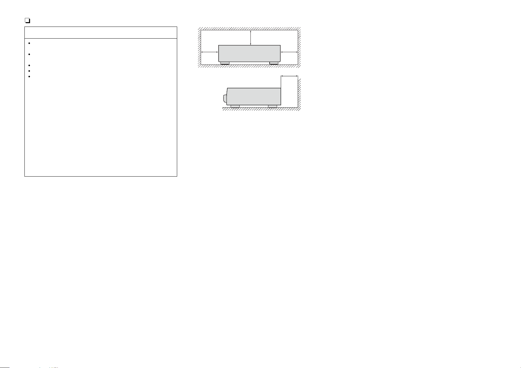
n CAUTIONS ON INSTALLATION
WARNINGS
•Avoid high temperatures.
Allow for sufficient heat dispersion when installed in a rack.
•Handle the power cord carefully.
Hold the plug when unplugging the cord.
•Keep the unit free from moisture, water, and dust.
•Unplug the power cord when not using the unit for long periods of time.
•Do not obstruct the ventilation holes.
•Do not let foreign objects into the unit.
•Do not let insecticides, benzene, and thinner come in contact with the unit.
•Never disassemble or modify the unit in any way.
•Ventilation should not be impeded by covering the ventilation openings
with items, such as newspapers, tablecloths or curtains.
•Naked flame sources such as lighted candles should not be placed on
the unit.
•Observe and follow local regulations regarding battery disposal.
•Do not expose the unit to dripping or splashing fluids.
•Do not place objects filled with liquids, such as vases, on the unit.
•Do not handle the mains cord with wet hands.
•When the switch is in the OFF (STANDBY) position, the equipment is not
completely switched off from MAINS.
•The equipment shall be installed near the power supply so that the power
supply is easily accessible.
•Do not keep the battery in a place exposed to direct sunlight or in places
with extremely high temperatures, such as near a heater.
z
z
z
z
Wall
z For proper heat dispersal, do not install this unit in a confined
space, such as a bookcase or similar enclosure.
•More than 0.3 m is recommended.
•Do not place any other equipment on this unit.
II
Getting started
Preparations
Operations
Information
Thank you for purchasing this DENON product. To ensure proper operation, please read this owner’s manual carefully before using the product.
After reading them, be sure to keep them for future reference.
Contents
Getting started ·············································································· 1
Accessories ··················································································1
Features ························································································ 2
Cautions on handling ····································································2
Preparations ·············································································3
Connections ··················································································· 4
Cables used for connections ························································4
Connecting the speakers ······························································ 4
Connecting players ······································································· 6
Connecting a recorder ··································································7
Connecting the power cord ·························································· 7
Operations ················································································8
Operations ·····················································································9
Before use ···················································································· 9
Starting playback···········································································9
Starting recording ·······································································10
Setting the Auto Standby mode ·················································10
Information ·············································································11
Part names and functions···························································12
Front panel ·················································································· 12
Rear panel ··················································································· 13
Remote control unit ···································································· 14
Explanation terms ······································································· 15
Troubleshooting ·········································································· 16
Specifications ··············································································17
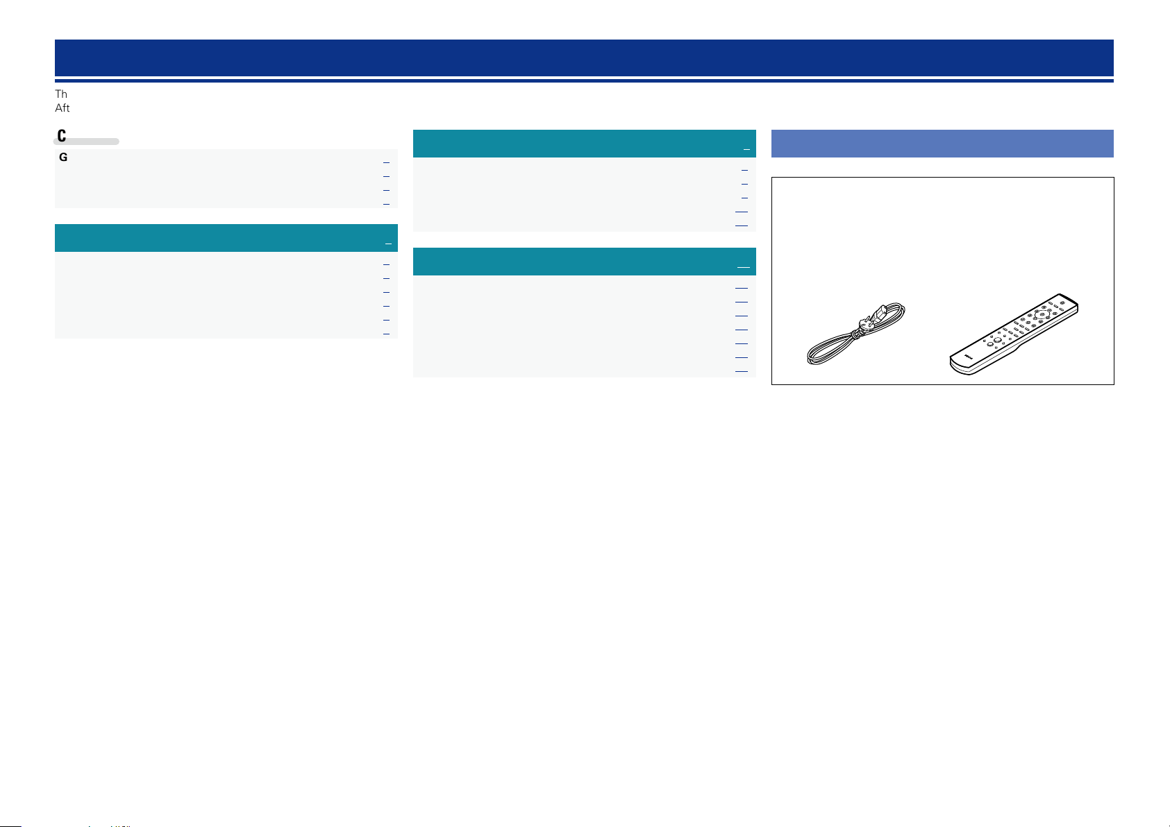
Accessories
Check that the following parts are supplied with the product.
q Getting Started ........................................................................ 1
w CD-ROM (Owner’s manual) .................................................... 1
e Safety Instructions .................................................................. 1
r Service network list ................................................................. 1
t Power cord .............................................................................. 1
y Remote control unit (RC-1179) ................................................ 1
u R03/AAA batteries ................................................................... 2
t
y
1

Features
Preparations
Operations
Information
Cautions on handling
Advanced UHC-MOS Single Push-pull Circuit
The new generation UHC-MOS FET is employed for the power
amplifier output stage.
The steady current is scaled up from 30 A to 70 A and the
instantaneous current from 120 A to 210 A.
The operation stability affected by the temperature fluctuation is
improved by using the dual FET selected first stage for the voltage
amplifier stage. Furthermore, the phase property is stabilized up to
the high range by using the cascade bootstrap circuit.
Power Supply
To make the most of the Advanced UHC-MOS Single Push–pull
Circuit, this powerful power supply consists of a LC mount twin
transformer, schottky barrier diodes that have 50% more current
capacity compared to the conventional ones, and a custom block
type capacitor that is tuned for high-quality sound.
Flat Amp
A FET output flat amplifier of a full discrete configuration that
has a high-quality local stabilizer power supply is included in the
preamplifier section.
Phono Equalizer
Even a user who is particular about analog records is satisfied
because the Phono Equalizer circuit for the FET input supports
MM/MC.
Power Amp Direct
A Power Amp Direct input that can also be used for a standalone
power amplifier is equipped, useful for combining with the audio
system and home theater system, etc.
Pre Out
A Pre Out connector is equipped that can extend the system’s
possibility by using another power amplifier to drive a bi-amplifier
with a speaker that supports the bi-wiring or adding a subwoofer
to upgrade the system.
Mechanical Ground
A chassis that has 6 discrete blocks shielded for each signal level
and a foot made of high density materials pursue the Mechanical
Ground concept, eliminating the influences caused by external
vibration and preventing vibration of the transformer, the internal
vibration source, from being transmitted to the amplifier circuit.
•Before turning the power on
Check once again that all connections are correct and that there are
no problems with the connection cables.
•Power is supplied to some of the circuitry even when the unit is
set to the standby mode. When going on vacation or leaving home
for long periods of time, be sure to unplug the power cord from the
power outlet.
•About condensation
If there is a major difference in temperature between the inside of
the unit and the surroundings, condensation (dew) may form on
the operating parts inside the unit, causing the unit not to operate
properly.
If this happens, let the unit sit for an hour or two with the power
turned off and wait until there is little difference in temperature
before using the unit.
•Cautions on using mobile phones
Using a mobile phone near this unit may result in noise. If that
occurs, move the mobile phone away from this unit when it is in use.
•Moving the unit
Turn off the power and unplug the power cord from the power
outlet. Next, disconnect the connection cables to other system units
before moving the unit.
•About care
•Wipe the cabinet and control panel clean with a soft cloth.
•Follow the instructions when using a chemical cleaner.
•Benzene, paint thinner or other organic solvents as well as
insecticide may cause material changes and discoloration if brought
into contact with the unit, and should therefore not be used.
2
Preparations
Preparations
Operations
Information
Preparations
Preparations
Here, we explain the connections and set up methods for this unit.
F Cables used for connections vpage4
F Connecting the speakers vpage4
F Connecting players vpage6
F Connecting a recorder vpage7
F Connecting the power cord vpage7
3
Connections
Preparations
Operations
Information
Preparations
v See overleaf
Connections for all compatible audio signal format is described in
this operating instructions. Please select the types of connections
corresponding to the equipment you are connecting.
NOTE
•Do not plug in the power cord until all connections have been
completed.
•When making connections, also refer to the operating instructions of
the other components.
•Be sure to connect the left and right channels properly (left with left,
right with right).
•Do not bundle power cords with connection cables. Doing so can
result in humming or noise.
•Do not turn up the volume without a turntable connected to the
PHONO input terminals. Doing so will cause humming or noise.
n Cautions on playing SA sources:
When regular speakers not compatible with SA sources (DVD
Audio discs, Super Audio CDs and other sources, including
treble components above the audible range), set the properties
of the player (DVD Audio player, Super Audio CD player, etc.)
for use with regular speakers (or amplifiers).
The speakers may be damaged if the volume is set too high
when playing SA sources. For instructions on player settings,
refer to the operating instructions included with the player.
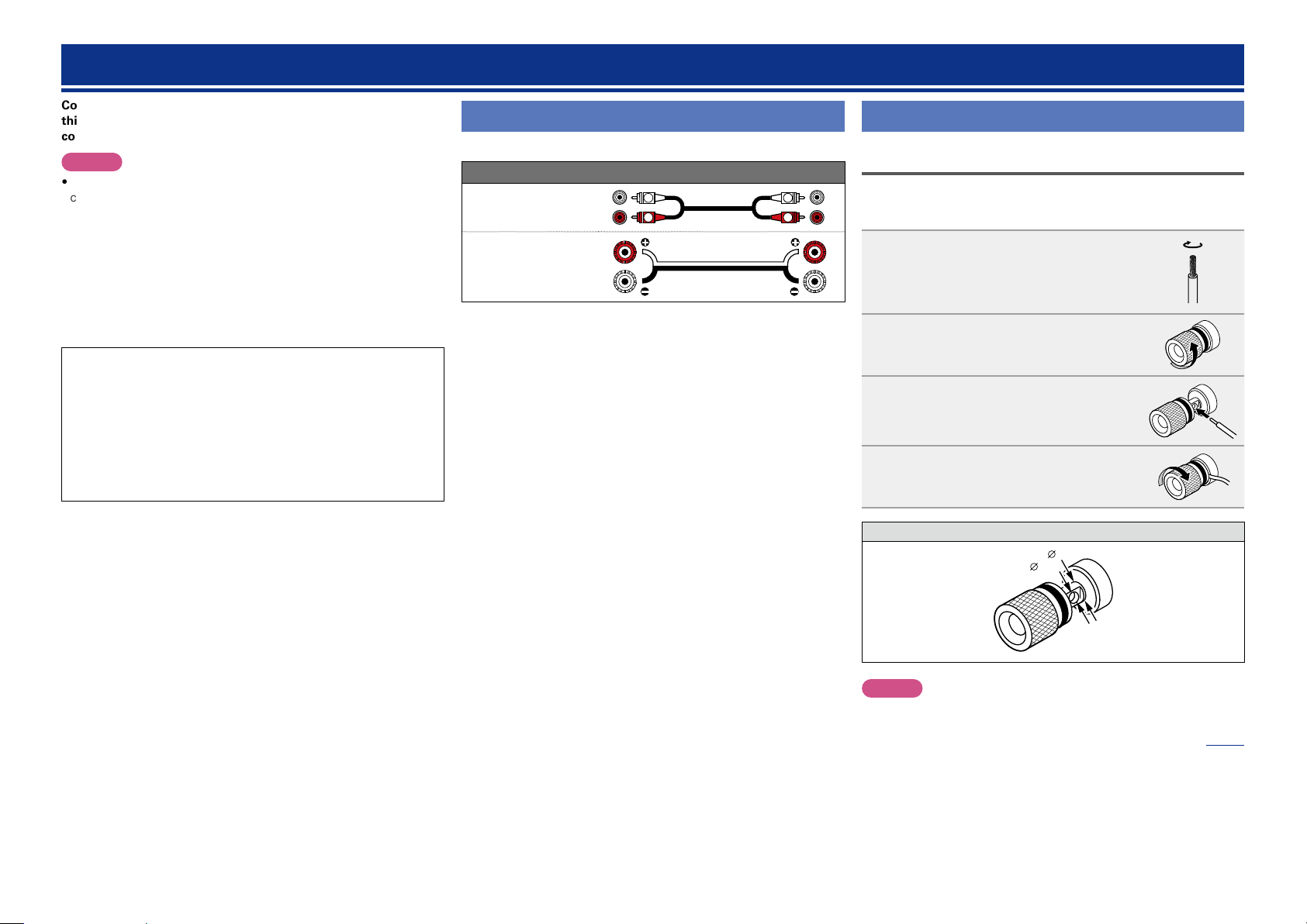
Cables used for connections
Select the cables according to the equipment being connected.
Audio cable (sold separately)
Audio cable
Speaker cable
L
R
L
R
Connecting the speakers
Connecting the speakers cables
Carefully check the left (L) and right (R) channels and + (red) and –
(black) polarities on the speakers being connected to the unit, and be
sure to connect the channels and polarities correctly.
Peel off about 10 mm of sheathing
1
from the tip of the speaker cable, then
either twist the core wire tightly or
apply solder to it.
Turn the speaker terminal
2
counterclockwise to loosen it.
Insert the speaker cable’s core wire to
3
all the way into the speaker terminal.
Turn the speaker terminal clockwise
4
to tighten it.
Speaker terminal dimensions
8mm
5mm
NOTE
•Connect the speaker cables so they do not stick out of the speaker
terminals. The protection circuit may be activated if the wires touch
the rear panel or if the + and – sides touch each other (vpage5
“Protection circuit”).
•Never touch the speaker terminals while the power supply is
connected. Doing so could result in electric shock.
4
 Loading...