

Page 1
REMOTECONTROLUNITRC-902
VOLUME
ENTER
BAND
MODE
MENU
FUNCTION
DISPLAY RETURN INPUT MODE SURROUND
TOP MENU
SETUP
SDB/TONE
MUTE
SURR.PARA
SUB TITLE ANGLE
AUDIO
SHIFT
CH.SELECT
CH
T.TONE
TU
PROG/DIRECT
REPEAT A-B
REPEAT RANDOM
DVD
TV/VCR
CH
VOL
SLEEP
ON
OFF
REMOCON MODE
2
3
4
56
8
9
CLEAR
CALL
0
+10
7
1
STATUS
CDR/MD/TAPE
TUNER/TV/VCR
VCR POWER
TV POWER
TV
VCR
NTSC/PAL
MEMO
POWER
CH
CH
CH
FUNCTION
/SELECT
MASTER VOLUME
ON / STANDBY
SURROUND
MODE
SDB/TONE
TIMER/SET
STATUS
OPEN/CLOSE
PHONES
DVD SURROUND
RECEIVER
ADV-700
1
c 8 1:02:46
DVD
TONE
- TUNING +BAND
DVD SURROUND RECEIVER
ADV-700
OPERATING INSTRUCTIONS
MODE D’EMPLOI
2
We greatly appreciate your purchase of this unit.
2
To be sure you take maximum advantage of all the
features this unit has to offer, read these instructions
carefully and use the set properly. Be sure to keep this
manual for future reference should any questions or
problems arise.
“SERIAL NO.
PLEASE RECORD UNIT SERIAL NUMBER ATTACHED TO
THE REAR OF THE CABINET FOR FUTURE REFERENCE”
“NO. DE SERIE
PRIERE DE NOTER LE NUMERO DE SERIE DE L’APPAREIL
INSCRIT A L’ARRIERE DU COFFRET DE FAÇON A POUVOIR
LE CONSULTER EN CAS DE PROBLEME.”
2
Nous vous remercions pour l’achat de cet appareil.
2
Pour être sûr de profiter au maximum de toutes les
caractéristiques qu’offre cet appareil, lire avec soin ces
instructions et bien utiliser l’appareil. Toujours
conserver ce mode d’emploi pour s’y référer
ultérieurement en cas de question ou de problème.
FOR ENGLISH READERS PAGE 4 ~ PAGE 85 POUR LES LECTEURS FRANCAIS PAGE 86 ~ PAGE 167
Page 2
2
2
SAFETY PRECAUTIONS
CAUTION:
TO REDUCE THE RISK OF ELECTRIC SHOCK, DO
NOT REMOVE COVER (OR BACK). NO USERSERVICEABLE PARTS INSIDE. REFER SERVICING
TO QUALIFIED SERVICE PERSONNEL.
The lightning flash with arrowhead symbol, within an
equilateral triangle, is intended to alert the user to the
presence of uninsulated “dangerous voltage” within the
product’s enclosure that may be of sufficient magnitude
to constitute a risk of electric shock to persons.
The exclamation point within an equilateral triangle is
intended to alert the user to the presence of important
operating and maintenance (servicing) instructions in
the literature accompanying the appliance.
CAUTION
TO PREVENT ELECTRIC SHOCK, MATCH WIDE BLADE OF PLUG
TO WIDE SLOT, FULLY INSERT.
ATTENTION
POUR ÉVITER LES CHOCS ÉLECTRIQUES, INTERODUIRE LA LAME
LA PLUS LARGE DE LA FICHE DANS LA BORNE
CORRESPONDANTE DE LA PRISE ET POUSSER JUSQU’ AU FOND.
This device complies with Part 15 of the FCC Rules. Operation is subject to
the following two conditions: (1) This device may not cause harmful
interference, and (2) this device must accept any interference received,
including interference that may cause undesired operation.
This Class B digital apparatus meets all requirements of the Canadian
Interference-Causing Equipment Regulations.
Cet appareil numérique de la classe B respecte toutes les exigences du
Règlement sur le matériel brouilleur du Canada.
WARNING:
TO PREVENT FIRE OR SHOCK HAZARD, DO NOT EXPOSE
THIS APPLIANCE TO RAIN OR MOISTURE.
2
NOTE ON USE / OBSERVATIONS RELATIVES A L’UTILISATION
• Avoid high temperatures.
Allow for sufficient heat dispersion when
installed on a rack.
• Eviter des températures élevées
Tenir compte d’une dispersion de chaleur
suffisante lors de l’installation sur une étagère.
• Handle the power cord carefully.
Hold the plug when unplugging the cord.
• Manipuler le cordon d’alimentation avec
précaution.
Tenir la prise lors du débranchement du cordon.
• Keep the set free from moisture, water, and
dust.
• Protéger l’appareil contre l’humidité, l’eau et
lapoussière.
• Unplug the power cord when not using the set
for long periods of time.
• Débrancher le cordon d’alimentation lorsque
l’appareil n’est pas utilisé pendant de longues
périodes.
* (For sets with ventilation holes)
• Do not obstruct the ventilation holes.
• Ne pas obstruer les trous d’aération.
• Do not let foreign objects in the set.
• Ne pas laisser des objets étrangers dans
l’appareil.
• Do not let insecticides, benzene, and thinner
come in contact with the set.
• Ne pas mettre en contact des insecticides, du
benzène et un diluant avec l’appareil.
• Never disassemble or modify the set in any
way.
• Ne jamais démonter ou modifier l’appareil
d’une manière ou d’une autre.
CAUTION:
1. Handle the power supply cord carefully
Do not damage or deform the power supply cord. If it is damaged or
deformed, it may cause electric shock or malfunction when used.
When removing from wall outlet, be sure to remove by holding the plug
attachment and not by pulling the cord.
2. Do not open the top cover
In order to prevent electric shock, do not open the top cover.
3. Do not place anything inside
Do not place metal objects or spill liquid inside the DVD video player.
Electric shock or malfunction may result.
NOTE:
This DVD video player uses the semiconductor laser. To allow you to enjoy
music at a stable operation, it is recommended to use this in a room of 5
°C (41 °F) ~ 35 °C (95 °F).
Copyrights
2
It is prohibited by law to reproduce, broadcast, rent or play discs in
public without the consent of the copyright holder.
CAUTION
RISK OF ELECTRIC SHOCK
DO NOT OPEN
Page 3

3
SAFETY INSTRUCTIONS
1. Read Instructions – All the safety and operating instructions
should be read before the product is operated.
2. Retain Instructions – The safety and operating instructions
should be retained for future reference.
3. Heed Warnings – All warnings on the product and in the
operating instructions should be adhered to.
4. Follow Instructions – All operating and use instructions should
be followed.
5. Cleaning – Unplug this product from the wall outlet before
cleaning. Do not use liquid cleaners or aerosol cleaners.
6. Attachments – Do not use attachments not recommended by
the product manufacturer as they may cause hazards.
7. Water and Moisture – Do not use this product near water – for
example, near a bath tub, wash bowl, kitchen sink, or laundry
tub; in a wet basement; or near a swimming pool; and the like.
8. Accessories – Do not place this product on an unstable cart,
stand, tripod, bracket, or table. The product may fall, causing
serious injury to a child or adult, and serious damage to the
product. Use only with a cart, stand, tripod, bracket, or table
recommended by the manufacturer, or sold with the product.
Any mounting of the product should follow the manufacturer’s
instructions, and should use a
mounting accessory
recommended by the
manufacturer.
9. A product and cart
combination should be
moved with care. Quick
stops, excessive force,
and uneven surfaces may
cause the product and cart
combination to overturn.
10. Ventilation – Slots and openings in the cabinet are provided for
ventilation and to ensure reliable operation of the product and to
protect it from overheating, and these openings must not be
blocked or covered. The openings should never be blocked by
placing the product on a bed, sofa, rug, or other similar surface.
This product should not be placed in a built-in installation such
as a bookcase or rack unless proper ventilation is provided or
the manufacturer’s instructions have been adhered to.
11. Power Sources – This product should be operated only from the
type of power source indicated on the marking label. If you are
not sure of the type of power supply to your home, consult your
product dealer or local power company. For products intended
to operate from battery power, or other sources, refer to the
operating instructions.
12. Grounding or Polarization – This product may be equipped with
a polarized alternating-current line plug (a plug having one blade
wider than the other). This plug will fit into the power outlet
only one way. This is a safety feature. If you are unable to
insert the plug fully into the outlet, try reversing the plug. If the
plug should still fail to fit, contact your electrician to replace your
obsolete outlet. Do not defeat the safety purpose of the
polarized plug.
13. Power-Cord Protection – Power-supply cords should be routed
so that they are not likely to be walked on or pinched by items
placed upon or against them, paying particular attention to
cords at plugs, convenience receptacles, and the point where
they exit from the product.
15. Outdoor Antenna Grounding – If an outside antenna or cable
system is connected to the product, be sure the antenna or
cable system is grounded so as to provide some protection
against voltage surges and built-up static charges. Article 810
of the National Electrical Code, ANSI/NFPA 70, provides
information with regard to proper grounding of the mast and
supporting structure, grounding of the lead-in wire to an
antenna discharge unit, size of grounding conductors, location
of antenna-discharge unit, connection to grounding electrodes,
and requirements for the grounding electrode. See Figure A.
16. Lightning – For added protection for this product during a
lightning storm, or when it is left unattended and unused for
long periods of time, unplug it from the wall outlet and
disconnect the antenna or cable system. This will prevent
damage to the product due to lightning and power-line surges.
17. Power Lines – An outside antenna system should not be
located in the vicinity of overhead power lines or other electric
light or power circuits, or where it can fall into such power lines
or circuits. When installing an outside antenna system,
extreme care should be taken to keep from touching such
power lines or circuits as contact with them might be fatal.
18. Overloading – Do not overload wall outlets, extension cords, or
integral convenience receptacles as this can result in a risk of
fire or electric shock.
19. Object and Liquid Entry – Never push objects of any kind into
this product through openings as they may touch dangerous
voltage points or short-out parts that could result in a fire or
electric shock. Never spill liquid of any kind on the product.
20.
Servicing – Do not attempt to service this product yourself as
opening or removing covers may expose you to dangerous
voltage or other hazards. Refer all servicing to qualified
service personnel.
21.
Damage Requiring Service – Unplug this product from the
wall outlet and refer servicing to qualified service
personnel
under the following conditions:
a) When the power-supply cord or plug is damaged,
b) If liquid has been spilled, or objects have fallen into the
product,
c) If the product has been exposed to rain or water,
d) If the product does not operate normally by following the
operating instructions. Adjust only those controls that are
covered by the operating instructions as an improper
adjustment of other controls may result in damage and will
often require extensive work by a qualified technician to
restore the product to its normal operation,
e) If the product has been dropped or damaged in any way, and
f) When the product exhibits a distinct change in performance
– this indicates a need for service.
22. Replacement Parts – When replacement parts are required, be
sure the service technician has used replacement parts
specified by the manufacturer or have the same characteristics
as the original part. Unauthorized substitutions may result in
fire, electric shock, or other hazards.
23. Safety Check – Upon completion of any service or repairs to this
product, ask the service technician to perform safety checks to
determine that the product is in proper operating condition.
24. Wall or Ceiling Mounting – The product should be mounted to a
wall or ceiling only as recommended by the manufacturer.
25. Heat – The product should be situated away from heat sources
such as radiators, heat registers, stoves, or other products
(including amplifiers) that produce heat.
FIGURE A
EXAMPLE OF ANTENNA GROUNDING
AS PER NATIONAL
ELECTRICAL CODE
ANTENNA
LEAD IN
WIRE
GROUND
CLAMP
ELECTRIC
SERVICE
EQUIPMENT
ANTENNA
DISCHARGE UNIT
(NEC SECTION 810-20)
GROUNDING CONDUCTORS
(NEC SECTION 810-21)
GROUND CLAMPS
POWER SERVICE GROUNDING
ELECTRODE SYSTEM
(NEC ART 250, PART H)
NEC - NATIONAL ELECTRICAL CODE
Page 4
4
ENGLISH
2
INTRODUCTION
2
ACCESSORIES
Thank you for choosing the DENON AVD-700 DVD Surround Receiver. This remarkable component has been engineered to provide superb surround
sound listening with home theater sources such as DVD, as well as providing outstanding high fidelity reproduction of your favorite music sources.
As this product is provided with an immense array of features, we recommend that before you begin hookup and operation that you review the
contents of this manual before proceeding.
TABLE OF CONTENTS
z BEFORE USING ..........................................................................................4
x CAUTIONS ON INSTALLATION ..................................................................4
c CAUTIONS ON HANDLING ........................................................................5
v FEATURES...................................................................................................5
b DISCS..........................................................................................................6
n CAUTIONS ON HANDLING DISCS.............................................................7
m CONNECTIONS ....................................................................................8~15
, PART NAMES AND FUNCTIONS........................................................16, 17
. REMOTE CONTROL UNIT..................................................................18~21
⁄0 SETTING UP THE SYSTEM ................................................................22~30
⁄1 PLAY BACK.........................................................................................31~34
⁄2 OPERATION........................................................................................35~37
⁄3 DOLBY / DTS SURROUND.................................................................38, 39
⁄4 SURROUND PLAYBACK.....................................................................40~47
⁄5 DSP SURROUND SIMULATION.........................................................48~51
⁄6 LISTENING TO THE RADIO................................................................52, 53
⁄7 ON-SCREEN DISPLAY ..............................................................................54
⁄8 USING THE ON-SCREEN DISPLAY....................................................55~66
⁄9 USING THE TIMER.............................................................................67~70
¤0 CHANGING THE DEFAULT SETTINGS (DVD).....................................71~81
¤1 LAST FUNCTION MEMORY .....................................................................82
¤2 INITIALIZATION OF THE MICROPROCESSOR........................................82
¤3 TROUBLESHOOTING .........................................................................83, 84
¤4 SPECIFICATIONS......................................................................................85
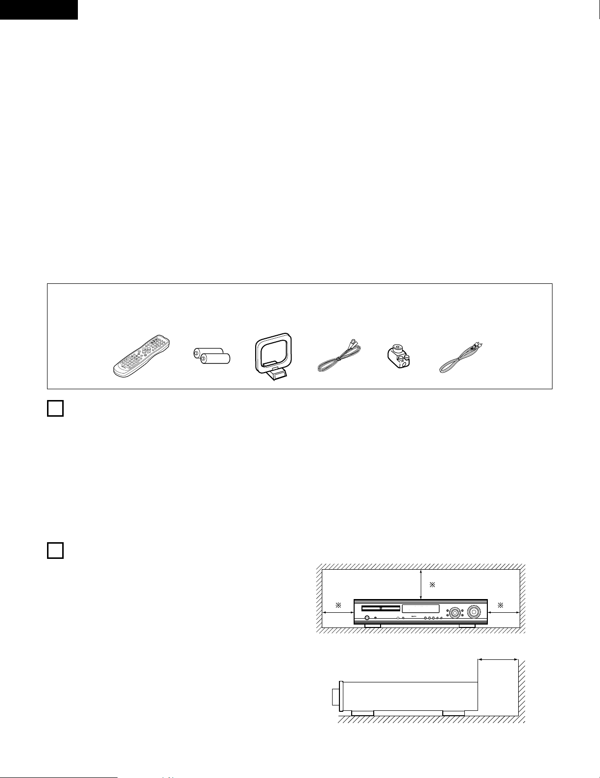
Check that the following parts are included in addition to the main unit:
q Operating instructions…..1 w Warranty ( for North America model only )………...........1 e Service station list…….....1 r Remote control unit
t R6P/AA batteries .............2 y AM loop antenna…...............1 u FM indoor antenna…1 i FM antenna adaptor……..1 (RC-902)............…......1
o Video cord .......................1
rtyu
V
O
L
U
M
E
B
A
N
D
MODE
M
E
N
U
F
U
N
C
T
I
O
N
DISPLAY
RETURN
INPUT MODE
SURROUND
TOP MENU
SETUP
SDB/TONE
MUTE
SURR.PARA
SUB
TITLE
ANGLE
AUDIO
S
H
I
F
T
CH.SELECT
CH
T.TONE
TU
P
R
O
G
/
D
I
R
E
C
T
R
E
P
E
A
T
A
B
REPEAT
RANDOM
D
V
D
TV/VCR
CH
VOL
SLEEP
O
N
O
F
F
R
E
M
O
C
O
N
M
O
D
E
2
3
4
5
6
8
9
0
7
1
S
T
A
T
U
S
C
D
R
/
M
D
/
T
A
P
E
T
U
N
E
R
/T
V
/V
C
R
VCR POWER
TV POWER
TV
VCR
N
T
S
C
/
P
A
L
E
N
T
E
R
MUTE
O
N
2
3
4
5
6
C
L
E
A
R
CALL
0
M
E
M
O
POWER
CH
CH
CH
O
F
F
1
8
9
+
1
0
7
io
1
2
BEFORE USING
CAUTIONS ON INSTALLATION
Pay attention to the following before using this unit:
• Moving the set
To prevent short circuits or damaged wires in the connection cords,
always unplug the power cord and disconnect the connection cords
between all other audio components when moving the set.
• Before turning the power switch on
Check once again that all connections are proper and that there are
not problems with the connection cords. Always set the power
switch to the standby position before connecting and disconnecting
connection cords.
Noise or disturbance of the picture may be generated if this unit or
any other electronic equipment using microprocessors is used near a
tuner or TV.
If this happens, take the following steps:
• Install this unit as far as possible from the tuner or TV.
• Set the antenna wires from the tuner or TV away from this unit’s
power cord and input/output connection cords.
• Noise or disturbance tends to occur particularly when using indoor
antennas or 300 Ω/ohms feeder wires. We recommend using
outdoor antennas and 75 Ω/ohms coaxial cables.
For heat dispersal, leave at least 10 cm/4 inch of space between
the top, back and sides of this unit and the wall or other
components.
• Store this instructions in a safe place.
After reading, store this instructions along with the warranty in a
safe place.
• Note that the illustrations in this instructions may differ from
the actual set for explanation purposes.
1
c 8 1:02:46
DVD
TONE
10 cm/4 inch or more
10 cm/4 inch or more
Wall
Page 5

5
ENGLISH
3
CAUTIONS ON HANDLING
4
FEATURES
• Switching the input function when input jacks are not
connected
A clicking noise may be produced if the input function is switched
when nothing is connected to the input jacks. If this happens, either
turn down the MASTER VOLUME control or connect components
to the input jacks.
• Muting of PRE OUT jacks, HEADPHONE jack and SPEAKER
terminals
The PRE OUT jacks, HEADPHONE jacks and SPEAKER terminals
include a muting circuit. Because of this, the output signals are
greatly reduced for several seconds after the power switch is
turned on or input function, surround mode or any other-set-up is
changed. If the volume is turned up during this time, the output will
be very high after the muting circuit stops functioning. Always wait
until the muting circuit turns off before adjusting the volume.
• Whenever the power switch is in the STANDBY state, the
apparatus is still connected on AC line voltage.
Please be sure to unplug the cord when you leave home for,
say, a vacation.
1. Dolby Digital decoder
Dolby Digital, a digital discrete system in which the different
channels are completely independent, recreates “threedimensional” sound fields (sounds with a sense of distance,
movement and position) with no crosstalk between channels for
greater reality. In addition, the 5 channels (excluding the 0.1
channel for low frequency effects) have a playback range
extending to 20 kHz, the same as the range of CDs, thus resulting
in clearer, more richly expressive sound.
2. Dolby Pro Logic II decoder
Dolby Pro Logic II is a new format for playing multichannel audio
signals that offers improvements over conventional Dolby Pro
Logic. It can be used to decode not only sources recorded in Dolby
Surround but also regular stereo sources into five channels (front
left/right, center and surround left/right). In addition, various
parameters can be set according to the type of source and the
contents, so you can adjust the sound field with greater precision.
3. DTS (Digital Theater Systems)
DTS provides up to 5.1 channels of wide-range, high fidelity
surround sound, from sources such as laser disc, DVD and
specially-encoded music discs.
4. High performance DSP simulates 7 sound fields
Playback is possible in 7 surround modes: 5-channel Stereo, Mono
Movie, Rock Arena, Jazz Club, Video Game, Matrix and Virtual. You
can enjoy a variety of sound effects for different movie scenes and
program sources even with stereo sources not in Dolby Surround.
5. Personal Memory Plus function
Personal Memory Plus is an advanced version of Personal
Memory. With Personal Memory Plus, the set automatically
memorizes the surround mode and input mode for each of the
separate input sources.
6. Remote control unit with pre-memory function
This unit comes with a remote control unit equipped with a prememory function. The remote control command codes for DENON
remote controllable components as well as for video decks, TVs,
etc., of other major manufacturers are prestored in the memory.
7. 5-channel power amplifier
The ADV-700 is equipped with a 35W + 35W (6 Ω/ohms, 1 kHz,
T.H.D. 10%) 5-channel power amplifier, allowing 5.1-channel
surround playback when used in combination with the super
woofer.
8. Many convenient functions
(1) Multiple audio function
Selection of up to 8 audio languages.
(The number of languages offered differs from DVD to DVD.)
(2) Multiple subtitle function
Selection of up to 32 subtitle languages.
(The number of languages offered differs from DVD to DVD.)
(3) Multiple angle function
The angle of view can be changed.
(For DVDs on which multiple angles are recorded.)
(4) Playback disable function
This function can be used to disable playback of DVDs you do
not want children to watch.
Page 6
6
ENGLISH
5
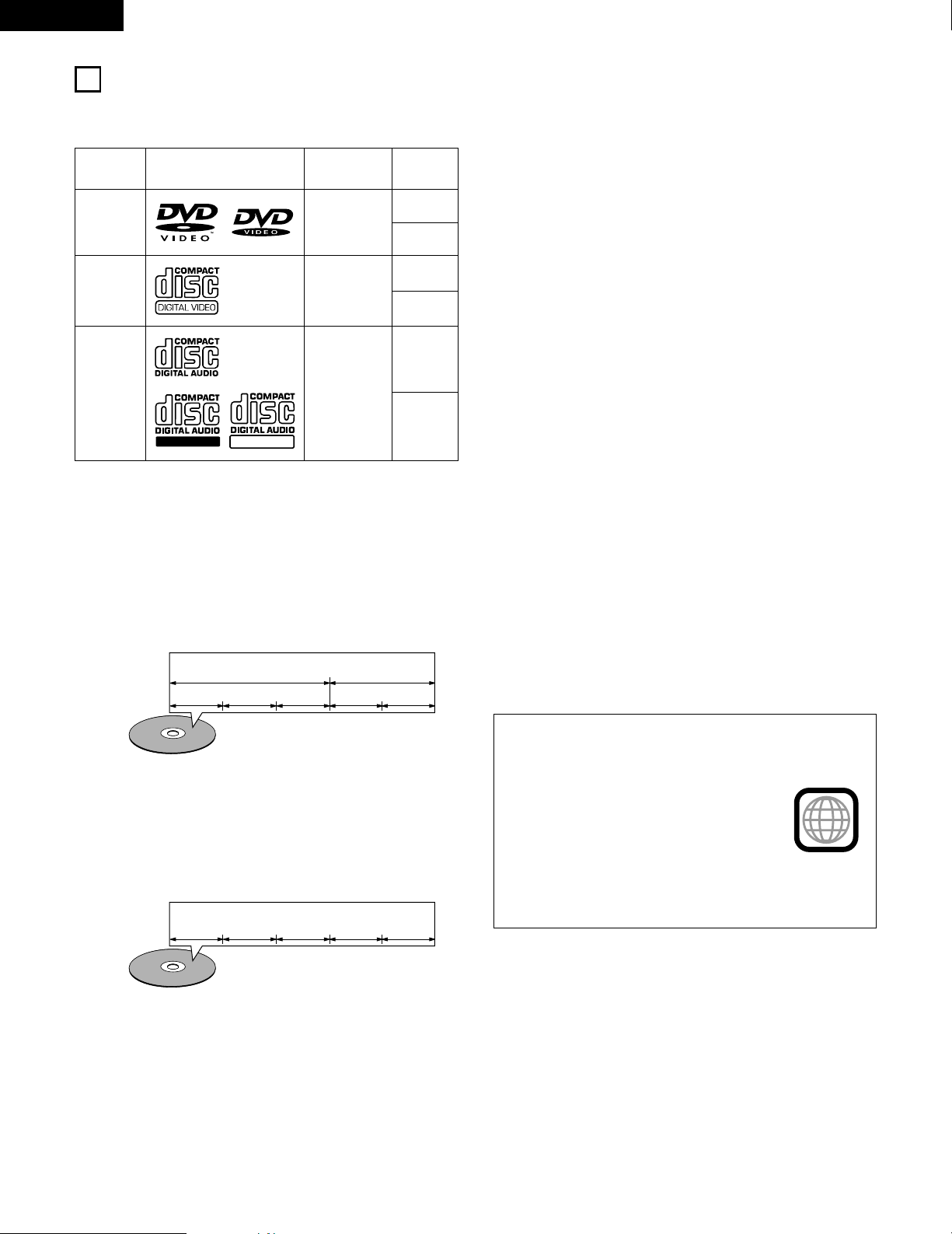
DISCS
• The types of discs listed on the table below can be used on the ADV-700.
The marks are indicated on the disc labels or jackets.
Usable
discs
Mark (logo)
Recorded
signals
Disc size
DVD video
DVD audio
(NOTE 1)
Digital audio +
digital video
(MPEG2)
12 cm
8 cm
12 cm
8 cm
12 cm
8 cm
Digital audio +
digital video
(MPEG1)
Digital audio
MP3
Video CD
CD
CD-R
CD-RW
(NOTE 2)
2 The following types of discs cannot be played on the
ADV-700:
• DVDs with region numbers other than “1” or “ALL”
• DVD audio discs (NOTE 1)
• DVD-R/ –RW / +RW
• DVD-ROM/RAMs
• CVD
• SVCD
• CD-ROMs (Only MP3 file can be played)
•VSDs
• CDVs (Only the audio part can be played.)
• CD-Gs (Only the audio is output.)
• Photo CDs (NEVER play such discs on the ADV-700)
✽ If you attempt to play photo CDs, the data on the disc may be
damaged.
NOTE 1: Video part which based on DVD-video specification only
can be played.
NOTE 2: According to recording quality, some CD-R/RW cannot
be played.
2 Disc terminology
• Titles and chapters (DVD-videos)
DVD-videos are divided into several large sections called
“titles” and smaller sections called “chapters”.
Numbers are allotted to these sections. These numbers are
called “title numbers” and “chapter numbers”.
• Playback control (video CDs)
Video CDs including the words “playback control” on the
disc or jacket are equipped with a function for displaying
menus on the TV screen for selecting the desired position,
displaying information, etc., in dialog fashion.
In this manual, playing video CDs using such menus is
referred to “menu playback”.
Video CDs with playback control can be used on the ADV-
700.
NOTE:
• This DVD video player is designed and
manufactured to respond to the Region
Management Information that is recorded
on a DVD disc.
If the Region number described on the
DVD disc does not correspond to the
Region number of this DVD video player,
this DVD video player cannot play this disc.
The Region number for this DVD video
player is 1.
• Tracks (video and music CDs)
Video and music CDs are divided into sections called
“tracks”.
Numbers are allotted to these sections. These numbers are
called “track numbers”.
For example:
For example:
Title 1
Chapter 1 Chapter 2 Chapter 3 Chapter 1 Chapter 2
Title 2
Track 1 Track 2 Track 3 Track 4 Track 5
1
Recordable
ReWritable
Page 7
7
ENGLISH
6
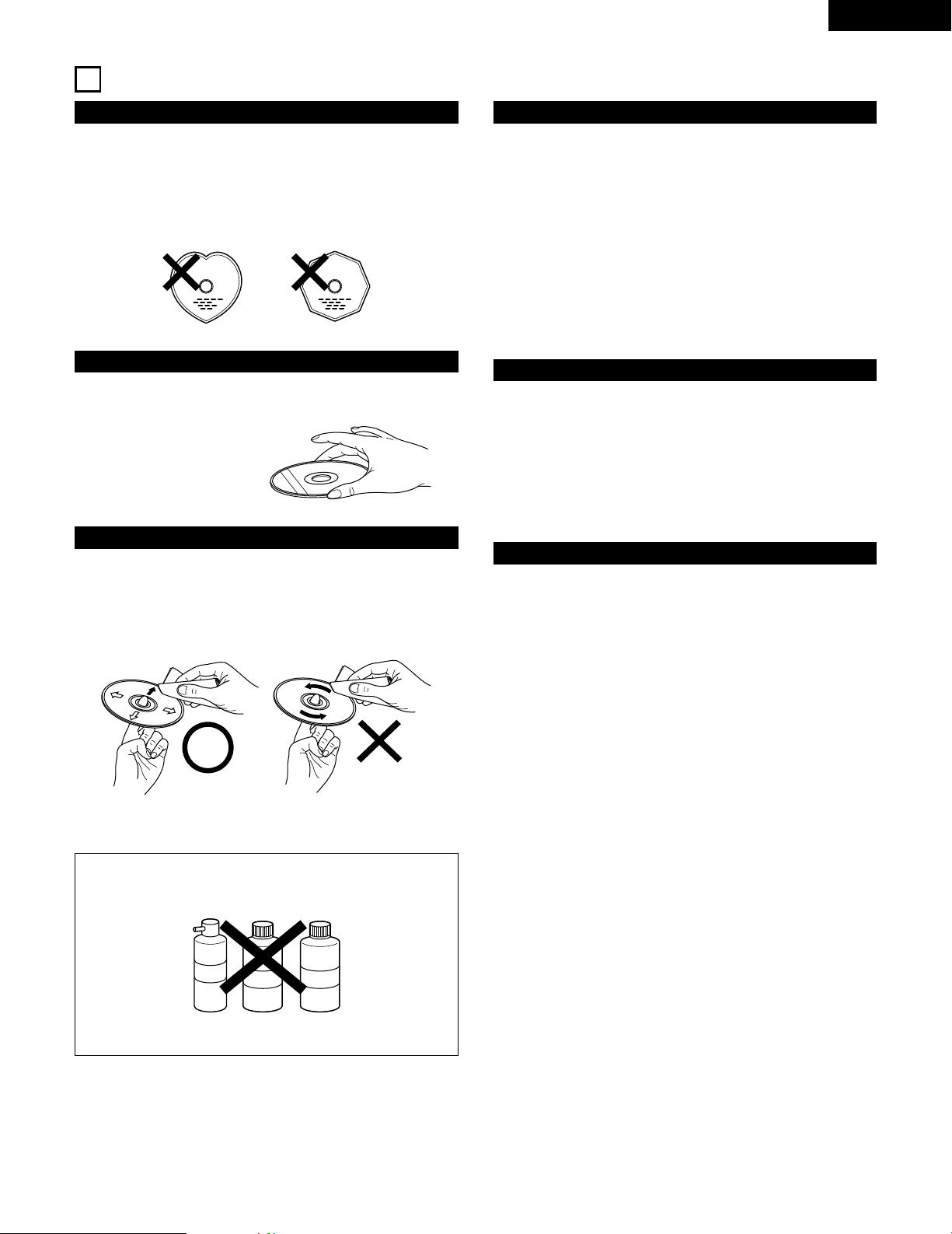
CAUTIONS ON HANDLING DISCS
Discs
Only the discs including the marks shown on page 6 can be
played on the ADV-700.
Note, however, that discs with special shapes (heart-shaped
discs, hexagonal discs, etc.) cannot be played on the ADV-700. Do
not attempt to play such discs, as they may damage the player.
Cautions on Handling Discs
• Do not get fingerprints, grease or dirt on discs.
• Be especially careful not to scratch discs when removing them
from their cases.
• Do not bend discs.
• Do not heat discs.
• Do not enlarge the center hole.
• Do not write on the labeled (printed) side with a ball-point pen
or a pencil.
• Water droplets may form on the surface if the disc is moved
suddenly from a cold place to a warm one. Do not use a
hairdryer, etc., to dry the disc.
Cautions on Storing Discs
• Always eject discs after playing them.
• Keep discs in their cases to protect them from dust, scratches
and warping.
• Do not put discs in the following places:
1. Places exposed to direct sunlight for long periods of time
2. Humid or dusty places
3. Places exposed to heat from heaters, etc.
Cautions on Loading Discs
• Only load one disc at a time. Loading one disc on top of another
may result in damage or scratch the discs.
• Load 8 cm discs securely in the disc guide, without using an
adapter. If the disc is not properly loaded, it may slip out of the
guide and block the disc tray.
• Be careful not to let your fingers get caught when the disc tray
is closing.
• Do not place anything but discs in the disc tray.
• Do not load cracked or warped discs or discs that have been
fixed with adhesive, etc.
• Do not use discs on which the adhesive part of cellophane tape
or glue used to attach the label is exposed, or discs with traces
of tape or labels that have been peeled off. Such discs may get
stuck inside the player, resulting in damage.
Holding Discs
Avoid touching the surface of discs when loading and unloading
them.
Cleaning Discs
2
Fingerprints or dirt on the disc may lower sound and picture
quality or cause breaks in playback. Wipe off fingerprints or
dirt.
2
Use a commercially available disc cleaning set or a soft cloth to
wipe off fingerprints or dirt.
Be careful not to get
fingerprints on the signal
surface (the side which
shines in rainbow colors).
Wipe gently from the middle
outwards.
Do not wipe with a circular
motion.
NOTE:
• Do not use record spray or antistatic. Also do not use
volatile chemicals such as benzene or thinner.
Record
spray
Thinner Benzene
Page 8
8
ENGLISH
VIDEO
MON.OUT
S VIDEO
IN IN ININ OUT
TV/DBS
V.AUX
VCR
R
L
AUDIO
IN OUT IN IN ININ OUT
V.AUXTV/DBS VCR
CDR/
TAPE
PRE OUT
SUB WOOFER
IN IN OUT
V.AUXTV/DBS
(OPTICAL)
DIGITAL
SPEAKER SYSTEMS
6 16
R
L
R
L
IMPEDANCE
CENTER SURROUNDFRONT
MON.OUT
Y CB CR
AM
FM COAX. 75
LOOP
ANT.
COMPONENT VIDEO OUT
OPTICAL
IN
OUTPUT
L
R
INPUT
LR
L
R
R
L
L
R
L
R
B
7
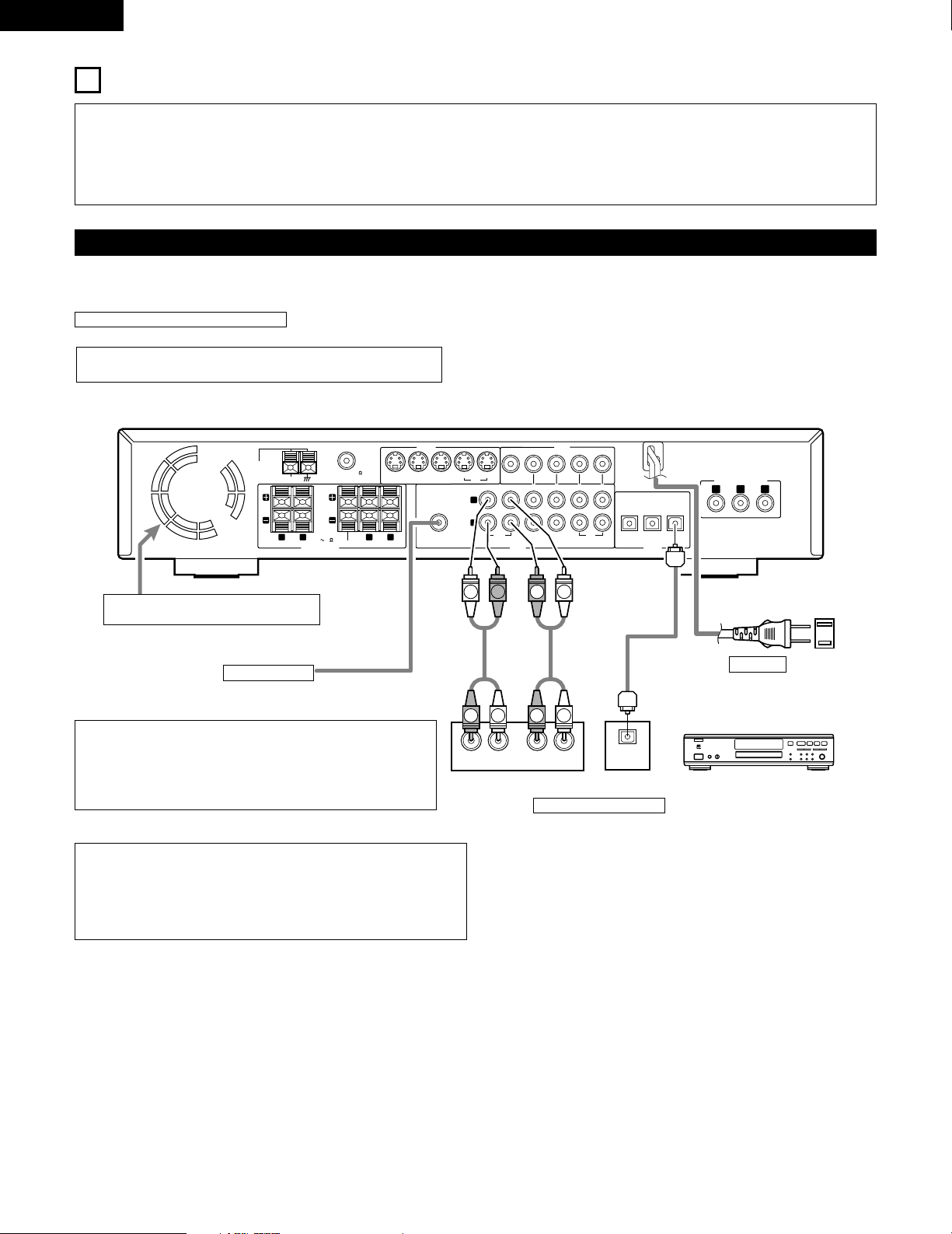
CONNECTIONS
• Do not plug in the AC cord until all connections have been
completed.
• Be sure to connect the left and right channels properly (left with
left, right with right).
• Insert the plugs securely. Incomplete connections will result in the
generation of noise.
• Note that binding pin plug cords together with AC cords or placing
them near a power transformer will result in generating hum or
other noise.
• Noise or humming may be generated if a connected audio
equipment is used independently without turning the power of this
unit on. If this happens, turn on the power of the this unit.
(1) Connecting the audio components
• When making connections, also refer to the operating instructions of the other components.
Subwoofer jack
Connect the internal amplifier’s subwoofer to the
subwoofer terminal. (Refer to page 14.)
•
To conduct digital recording onto a digital recorder (CD recorder, MD recorder, etc.)
while playing Dolby Digital, 96 kHz PCM sources on this DVD player.
•
Set the “AUDIO SETUP” default setting as shown below. (See page 77, 78.)
• “DIGITAL OUT”
→ “PCM”
“LPCM SELECT” → “ON”
Playing DVDs with incorrect settings may result noise that could damage your ears or
the speakers.
AC CORD
AC 120 V, 60 Hz
Connecting a recorder
Connections for recording:
Connect the tape deck’s recording input jacks (LINE IN or REC) to this unit’s tape
recording (CDR/TAPE OUT) jacks using pin plug cords.
Connections for playback:
Connect the tape deck’s playback output jacks (LINE OUT or PB) to this unit’s tape
playback (CDR/TAPE IN) jacks using pin plug cords.
CD recorder, MD recorder or Tape deck
Route the connection cords, etc., in such a way
that they do not obstruct the ventilation holes.
Connecting the DIGITAL (optical) jacks
Use these for connections to audio equipment with digital (optical) output.
NOTES:
• Use optical cables for optical connections, removing the cap before connecting.
NOTE:
•
Track numbers may not be added automatically when making digital
recordings of CDs being played on the ADV-700 onto a connected recorder.
•
When making digital recordings on a CD recorder, set the CD recorder’s
recording setting to manual and add track numbers (track marks) manually as
you record.
•
When making digital recordings on an MD recorder, use the editing function
after the recording is completed to divide the tracks.
Page 9
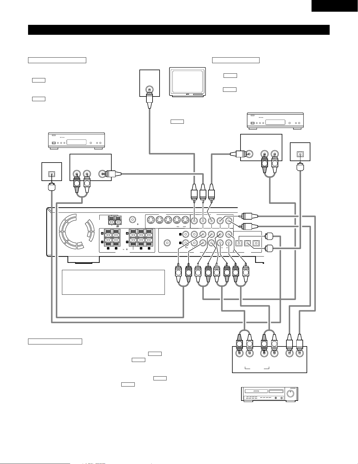
Video input/output connections:
• Connect the video deck’s video output jack (VIDEO OUT) to the (yellow) VCR IN jack, and
the video deck’s video input jack (VIDEO IN) to the (yellow) VCR OUT jack using 75
Ω/ohms video coaxial pin plug cords.
Connecting the audio output jacks
• Connect the video deck’s audio output jacks (AUDIO OUT) to the VCR IN jacks, and the
video deck’s audio input jacks (AUDIO IN) to the VCR OUT jacks using pin plug cords.
AUDIO
AUDIO
VIDEO
VIDEO
MONITOR OUT
• Connect the TV’s video
input jack (VIDEO INPUT) to
the MONITOR
OUT jack using a 75
Ω/ohms video coaxial pin
plug cord.
VIDEO
9
ENGLISH
VIDEO
MON.OUT
S VIDEO
IN IN ININ OUT
TV/DBS
V.AUX
VCR
R
L
AUDIO
IN OUT IN IN ININ OUT
V.AUXTV/DBS VCR
CDR/
TAPE
PRE OUT
SUB WOOFER
IN IN OUT
V.AUXTV/DBS
(OPTICAL)
DIGITAL
SPEAKER SYSTEMS
6 16
R
L
R
L
IMPEDANCE
CENTER SURROUNDFRONT
MON.OUT
YCB CR
AM
FM COAX. 75
LOOP
ANT.
VIDEO
OUT
AUDIO
OUT
L
R
VIDEO
OUT
INLR
OUT IN
L
R
AUDIO
OUT
OPTICAL
VIDEO
OUT
AUDIO
OUT
L
R
OUT
OPTICAL
VIDEO
IN
L
R
R
L
R
L
L
R
L
R
L
R
B
B
L
R
R
L
(2) Connecting video components
• To connect the video signal, connect using a 75 Ω/ohms video signal cable cord. Using an improper cable can result in a drop in video quality.
• When making connections, also refer to the operating instructions of the other components.
TV or DBS tuner
CS tuner
Connecting a TV/DBS tuner
TV/DBS
• Connect the TV’s or DBS tuner’s video
output jack (VIDEO OUTPUT) to the
(yellow) TV/DBS IN jack using a
75 Ω/ohms video coaxial pin plug cord.
• Connect the TV’s or DBS tuner’s audio
output jacks (AUDIO OUTPUT) to the
TV/DBS IN jacks using pin plug
cords.
• For devices with optical digital outputs,
connect the digital output terminal to the
ADV-700’s DIGITAL TV/DBS IN terminal
using an optical transmission cable.
AUDIO
VIDEO
Monitor TV
Connecting a CS tuner
V.AUX
• Connect the CS tuner’s video output jack (VIDEO OUTPUT) to
the (yellow) V.AUX IN jack using a 75 Ω/ohms video
coaxial pin plug cord.
• Connect the CS tuner’s audio output jacks (AUDIO OUTPUT) to
the V.AUX IN jacks using pin plug cords.
• For devices with optical digital outputs, connect the digital
output terminal to the ADV-700’s DIGITAL V.AUX. IN terminal
using an optical transmission cable.
AUDIO
VIDEO
Note on connecting the digital input jacks
• Only audio signals are input to the digital input jacks.
• Use optical cables for optical connections, removing
the cap before connecting.
Video deck
Connecting a video decks
Page 10
10
ENGLISH
VIDEO
MON.OUT
S VIDEO
IN IN ININ OUT
TV/DBS
V.AUX
VCR
R
L
AUDIO
IN OUT IN IN ININ OUT
V.AUXTV/DBS VCR
CDR/
TAPE
PRE OUT
SUB WOOFER
IN IN OUT
V.AUXTV/DBS
(OPTICAL)
DIGITAL
L
MON.OUT
Y CB CR
COMPONENT VIDEO OUT
S-VIDEO
IN
S-VIDEO
OUT
S-VIDEO
OUT
S-VIDEO INS-VIDEO
OUT
B
B
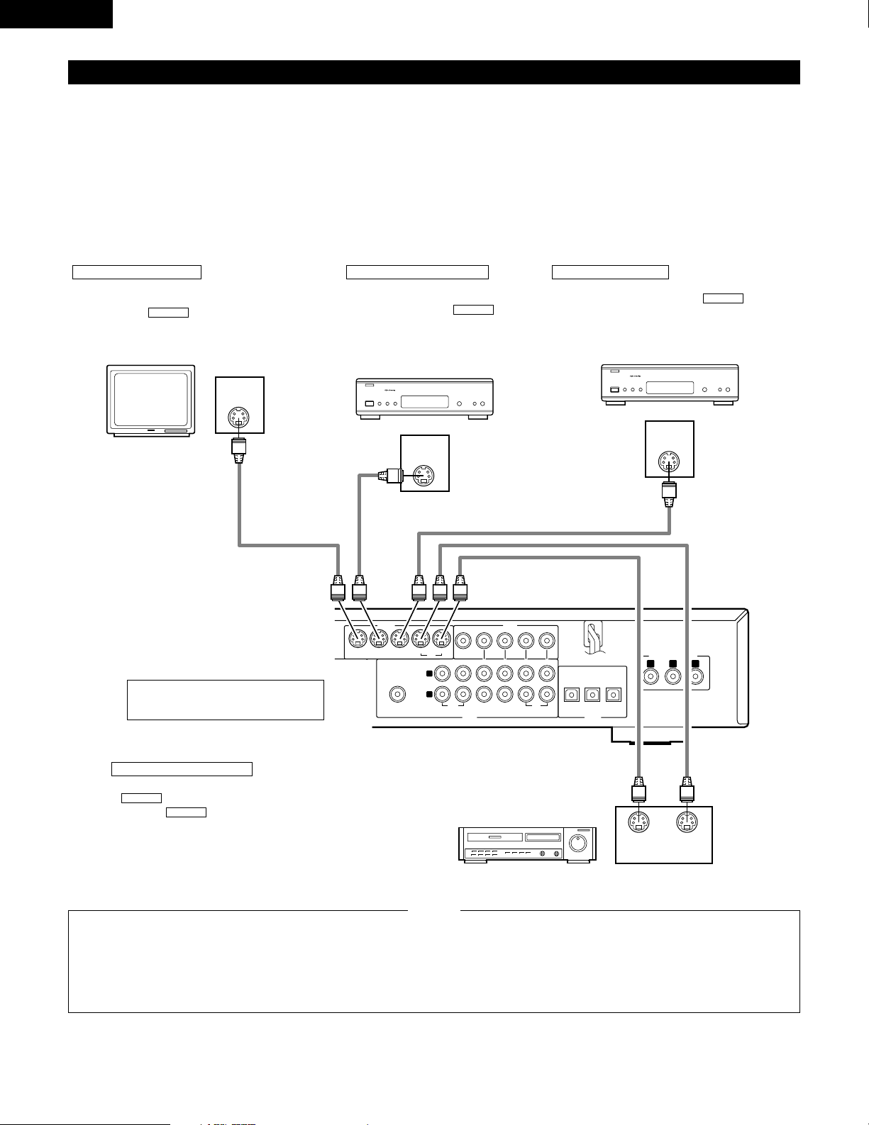
(3) Connecting a video component equipped with S-Video jacks
• When making connections, also refer to the operating instructions of the other components.
• A note on the S input jacks
The input selectors for the S inputs and pin jack inputs work in conjunction with each other.
• Precaution when using S-jacks
This unit’s S-jacks (input and output) and video pin jacks (input and output) have independent circuit structures, so that video signals input from
the S-jacks are only output from the S-jack outputs and video signals input from the pin jacks are only output from the pin jack outputs.
When connecting this unit with equipment that is equipped with S-jacks, keep the above point in mind and make connections according to the
equipment’s instruction manuals.
Connecting a monitor TV
MONITOR OUT
• Connect the TV’s S video input (S-VIDEO
INPUT) to the MONITOR OUT
jack using a S jack connection cord.
S-VIDEO
Monitor TV
Connecting a TV/DBS tuner
• Connect the TV’s or DBS tuner’s
S video output jack (S-VIDEO
OUTPUT) to the
TV/DBS IN jack using an S jack
connection cord.
S-VIDEO
Connecting a CS tuner
• Connect the CS tuner’s S video output
jack (S-VIDEO OUTPUT) to the
V.AUX. IN jack using an S jack connection
cord.
S-VIDEO
TV or DBS tuner
Connecting the video decks
• Connect the video deck’s S output jack (S-OUT) to the
VCR IN jack and the video deck’s S input jack (S-
IN) to the VCR OUT jack using S jack connection
cords.
S-VIDEO
S-VIDEO
Video deck
Connect the components’ audio inputs
and outputs as described on page 9.
• Connect this unit video outputs to the TV either directly. Do
not connect it via a VCR (video cassette recorder). Some
discs contain copy prohibit signals. If such discs are played
via a VCR, the copy prohibit system may cause disturbance
in the picture.
• Set the “TV TYPE” in “VIDEO SETUP” in “DVD SETUP” to
comply with your TV’s video format. When the TV is NTSC
formated set to NTSC.
NOTES:
CS tuner
Page 11
11
ENGLISH
1
4
2
3
R
L
L
R
YCB CR
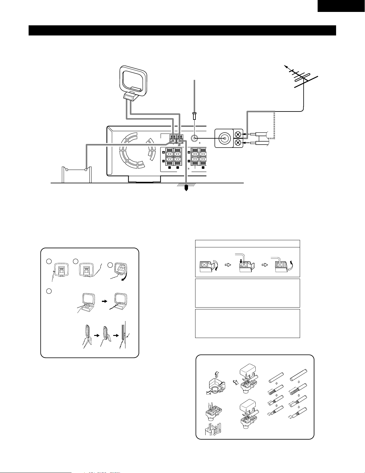
(4) Connecting the antenna terminals
DIRECTION OF
BROADCASTING
STATION
75 Ω/ohms
COAXIAL
CABLE
FM ANTENNA
FM INDOOR
ANTENNA
(Supplied)
AM LOOP
ANTENNA
(Supplied)
AM OUTDOOR
ANTENNA
GROUND
AM loop antenna assembly
Connect to the AM
antenna terminals.
Remove the vinyl tie
and take out the
connection line.
Bend in the reverse
direction.
a. With the antenna
on top any stable
surface.
b. With the antenna
attached to a wall.
Mount
Installation hole
Mount on wall, etc.
Connection of AM antennas
1. Push the lever. 2. Insert the conductor. 3. Return the lever.
Note to CATV system installer:
This reminder is provided to call the CATV system installer’s
attention to Article 820-40 of the NEC which provides guidelines
for proper grounding and, in particular, specifies that the cable
ground shall be connected to the grounding system of the
building, as close to the point of cable entry as practical.
Notes:
• Do not connect two FM antennas simultaneously.
• Even if an external AM antenna is used, do not disconnect the
AM loop antenna.
• Make sure AM loop antenna lead terminals do not touch metal
parts of the panel.
FM ANTENNA
ADAPTER
(Supplied)
• An F-type FM antenna cable plug can be connected directly.
• If the FM antenna cable’s plug is not of the F-type, connect using the included antenna adapter.
14mm
9mm
14mm
19mm
5mm
5mm
5C-2V3C-2V
5C-2V
FM antenna adopter assembly
75 Ω/ohms COAXIAL CABLE
Open the cover
ANTENNA ADAPTER
REMOVE
CLAMP
CLAMP
CLAMP
CLAMP
PULL
PULL
SHUT
SHUT
LOOP
ANT.
R
AM
FRONT
FM COAX. 75
IMPEDANCE
L
6 16
SPEAKER SYSTEMS
CENTER SUR
R
Page 12
12
ENGLISH
VIDEO
MON.OUT
S VIDEO
IN IN ININ OUT
TV/DBS
V.AUX
VCR
R
L
AUDIO
IN OUT IN IN ININ OUT
V.AUXTV/DBS VCR
CDR/
TAPE
PRE OUT
SUB WOOFER
IN IN OUT
V.AUXTV/DBS
(OPTICAL)
DIGITAL
SPEAKER SYSTEMS
6 16
R
L
R
L
IMPEDANCE
CENTER SURROUNDFRONT
MON.OUT
Y CB CR
AM
FM COAX. 75
LOOP
ANT.
COMPONENT VIDEO OUT
COMPONENT VIDEO IN
C
B CRY
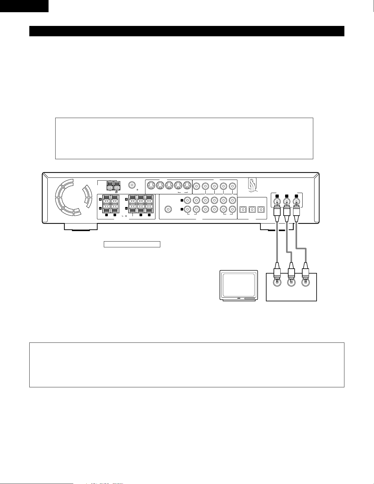
(5) Connecting to a TV or Monitor Equipped with Component Input Connectors.
• When making connections, also refer to the operating instructions of the other components.
• The video signals input to the VIDEO input (yellow) and S-Video input jacks are not output to the color difference (component) video jacks.
Connecting a monitor TV
MONITOR OUT jack
• Connect the TV’s color difference
(component) video input jacks
(COMPONENT VIDEO INPUT) to the
COMPONENT MONITOR OUT jack
using 75 Ω/ohms coaxial video pinplug cords.
Color component output connectors (CR, C
B and Y)
The red (C
R
), blue (CB) and brightness (Y) signals are output independently, achieving more faithful reproduction
of the colors.
• The color component input connectors may be marked differently on some TVs or monitors (P
R, PB and Y/R-
Y, B-Y and Y/C
R, CB and Y, etc.). For details, refer to the TV’s operating instructions.
NOTES:
• Use the three commercially available video cords to connect the ADV-700’s color component output connectors to the TV or
monitor.
• Set the “TV TYPE” in “VIDEO SETUP” in “DVD SETUP” to comply with your TV’s video format. When the TV is NTSC formated
set to NTSC.
Page 13
13
ENGLISH
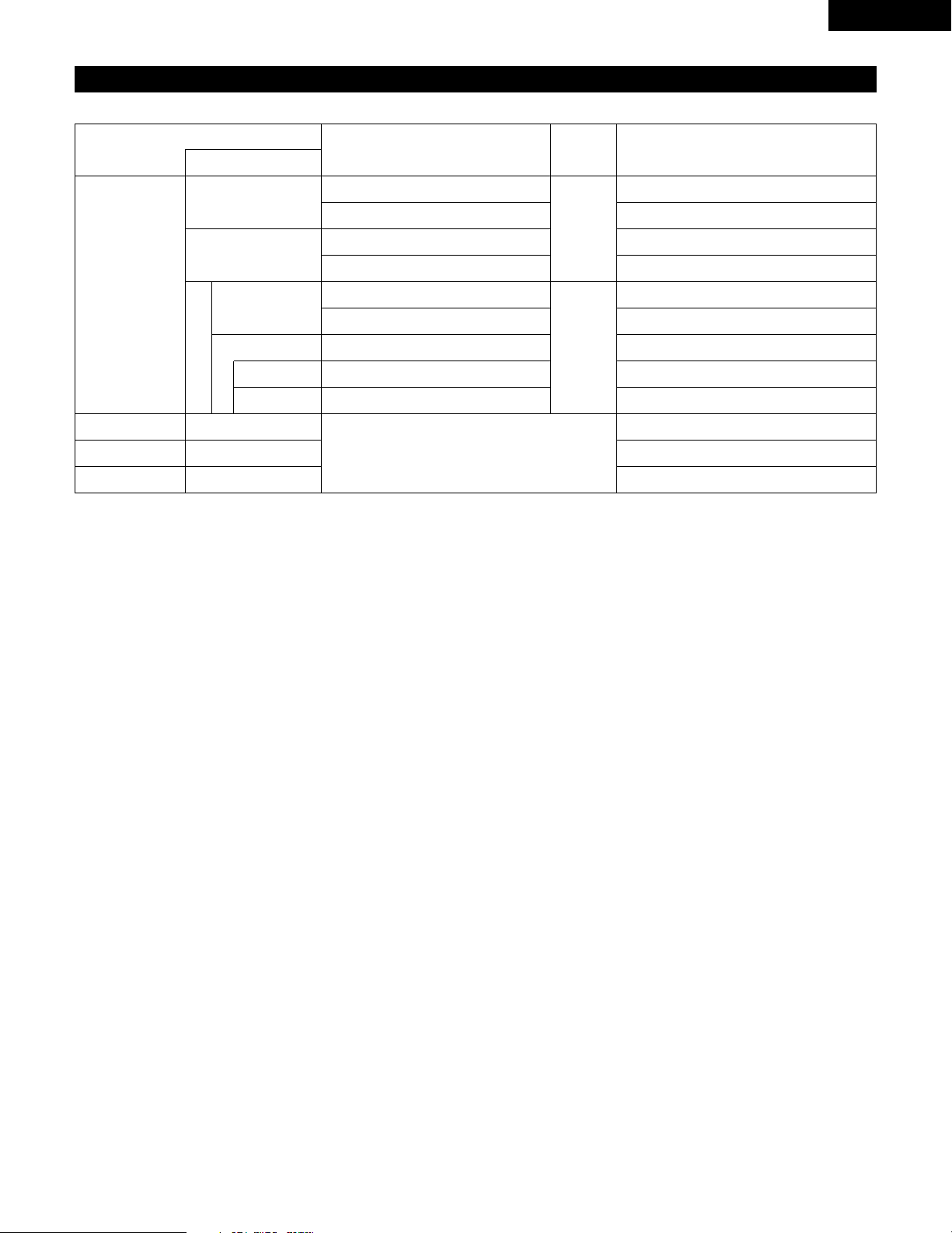
(6) Sound output from this unit digital audio output connectors
2 When a disc is played on the ADV-700
Refer to
page
DVD video
DVD audio
(video part only)
Audio recording format
Dolby Digital
CP : ON
Video CD
CP : OFF
DTS
48 kHz
• Linear PCM audio is the signal recording format used for music CDs.
While the signals are recorded at 44.1 kHz/16 bit for music CDs, for DVDs they are recorded at 48 kHz/16 bit to 96 kHz/24 bit, providing
higher sound quality than music CDs.
Music CD
MP3 CD
Linear PCM
96 kHz
32 ~ 48 kHz/16 bit PCM
44.1 kHz/16 bit PCM
44.1 kHz/16 bit PCM
LPCM conversion mode : OFF
LPCM conversion mode : OFF
MPEG 1
Linear PCM
MP 3
LPCM conversion mode : ON
LPCM conversion mode : ON
LPCM conversion mode : OFF
Digital out : PCM conversion
Digital out : Normal
Digital out : PCM conversion
Digital out : Normal
Settings
96 kHz PCM (when not copy-protected)
48 kHz/16 bit PCM (when copy-protected)
48 kHz/16 bit PCM
48 kHz/16 bit PCM
48 kHz/16 ~24 bit PCM
DTS bitstream
DTS bitstream
2 channels PCM data (48 kHz/16bit)
Dolby Digital bitstream
Digital audio data output
77
78
Page 14
14
ENGLISH
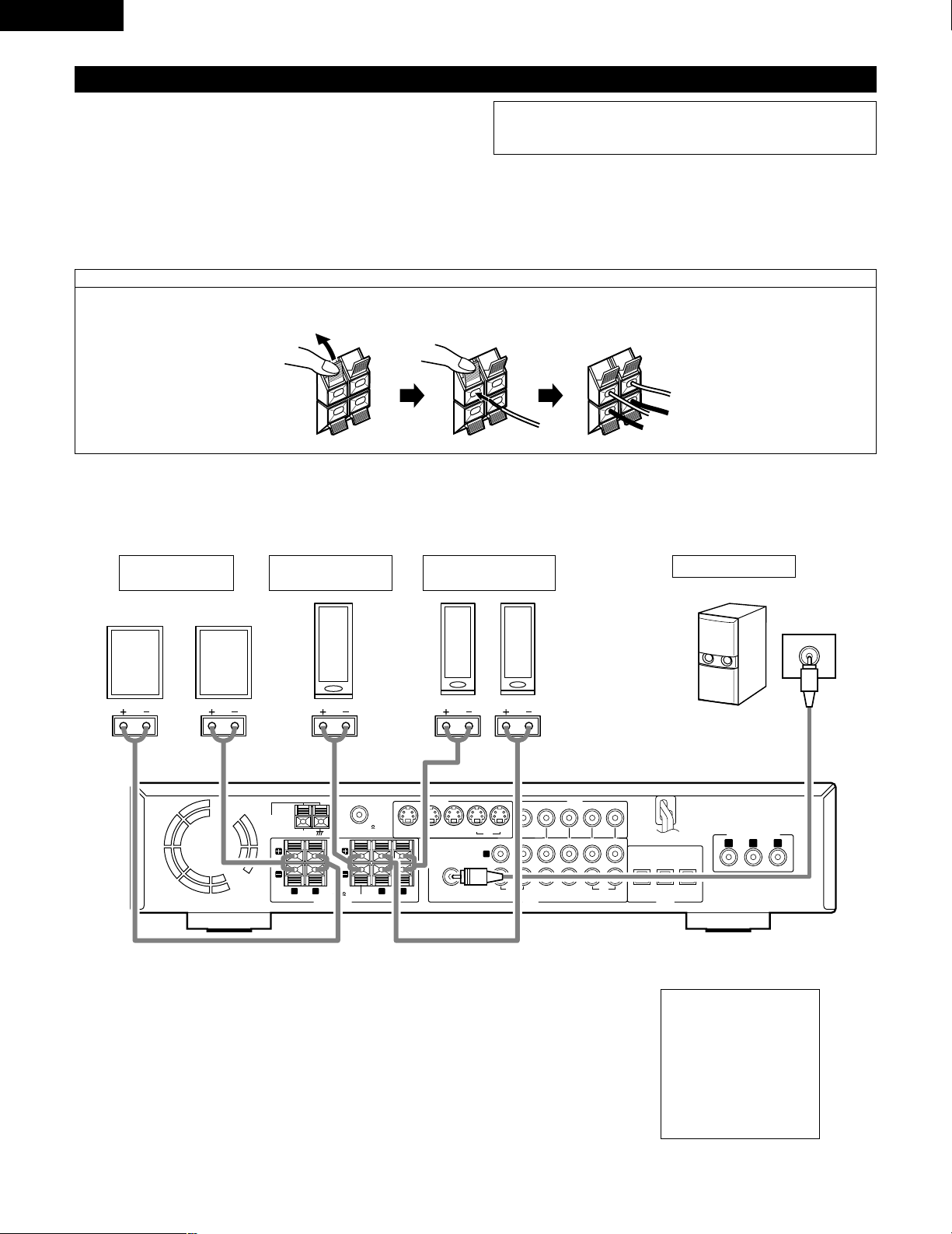
(7) Speaker system connections
• Use speaker cords with twisted wire cores and a diameter of 0.6 to 1.5 mm.
Never use cords thicker than 1.5 mm or single-wire cords, as they may
damage the speaker terminals.
• Be sure to interconnect the polarities of the terminals on the speakers and
main unit (≈ to ≈, √ to √).
• When making connections, be careful that none of the core wires of the
speaker cords stick out and touch neighboring terminals, other speaker cords
or the rear panel.
• Speakers with an impedance of 6 to 16 Ω/ohms can be connected for use as
center and surround speakers.
Connection the speaker terminals
1. Push the lever. 2. Insert the cord. 3. Return the lever.
Connections
• When making connections, also refer to the operating instructions of the other components.
NOTE:
NEVER touch the speaker terminals when the power is on.
Doing so could result in electric shocks.
• The protector circuit may be activated if the set is played for long periods of
time at high volumes when speakers with an impedance lower than the
specified impedance are connected.
• Precautions when
connecting speakers
If a speaker is placed near a
TV or video monitor, the
colors on the screen may
be disturbed by the
speaker’s magnetism. If
this should happen, move
the speaker away to a
position where it does not
have this effect.
VIDEO
MON.OUT
S VIDEO
IN IN ININ OUT
TV/DBS
V.AUX
VCR
R
L
AUDIO
IN OUT IN IN ININ OUT
V.AUXTV/DBS VCR
CDR/
TAPE
PRE OUT
SUB WOOFER
IN IN OUT
V.AUXTV/DBS
(OPTICAL)
DIGITAL
SPEAKER SYSTEMS
6 16
R
L
R
L
IMPEDANCE
CENTER SURROUNDFRONT
MON.OUT
Y CB CR
AM
FM COAX. 75
LOOP
ANT.
COMPONENT VIDEO OUT
(L) (R)
(L) (R)
FRONT SPEAKER
SYSTEMS
CENTER SPEAKER
SYSTEM
SURROUND
SPEAKER SYSTEMS
SUB WOOFER
Connector jack for subwoofer
with bilt-in amplifier (super
woofer), etc.
Page 15

15
ENGLISH
• This unit is equipped with a high-speed protection circuit. The purpose of this circuit is to protect the speakers under
circumstances such as when the output of the power amplifier is inadvertently short-circuited and a large current flows, when
the temperature surrounding the unit becomes unusually high, or when the unit is used at high output over a long period
which results in an extreme temperature rise.
When the protection circuit is activated, the speaker output is cut off and the power supply indicator LED flashes. Should
this occur, please follow these steps: be sure to switch off the power of this unit, check whether there are any faults with
the wiring of the speaker cables or input cables, and wait for the unit to cool down if it is very hot. Improve the ventilation
condition around the unit and switch the power back on.
If the protection circuit is activated again even though there are no problems with the wiring or the ventilation around the
unit, switch off the power and contact a DENON service center.
Protector circuit
• The protector circuit may be activated if the set is played for long periods of time at high volumes when speakers with an
impedance lower than the specified impedance (for example speakers with an impedance of lower than 4 Ω/ohms) are
connected. If the protector circuit is activated, the speaker output is cut off. Turn off the set’s power, wait for the set to cool
down, improve the ventilation around the set, then turn the power back on.
Note on speaker impedance
Page 16
16
ENGLISH
8
PART NAMES AND FUNCTIONS
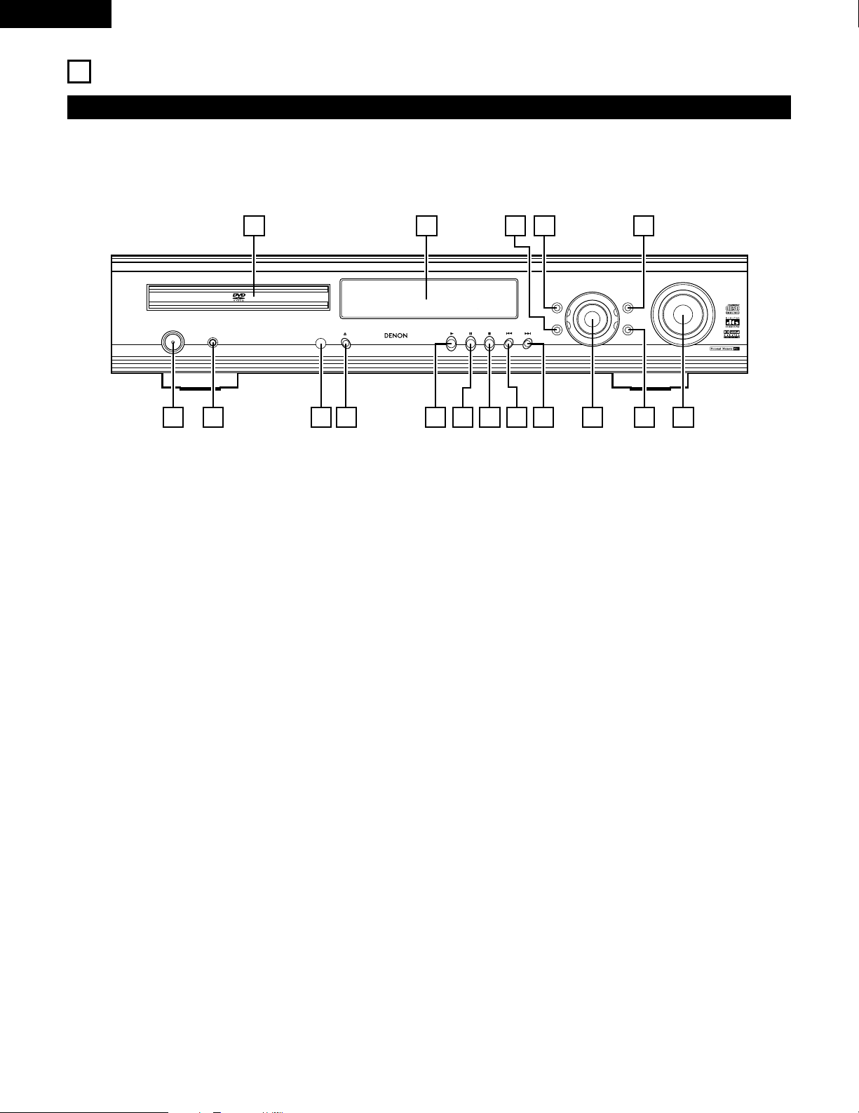
Front Panel
• For details on the functions of these parts, refer to the pages given in parentheses ( ).
FUNCTION
/SELECT
MASTER VOLUME
ON / STANDBY
SURROUND
MODE
SDB/TONE
TIMER/SET
STATUS
OPEN/CLOSE
PHONES
DVD SURROUND
RECEIVER
ADV-700
1
c 8 1:02:46
DVD
TONE
- TUNING +
BAND
1617 1415 13
1 2 3 4 5 6 7
10 11 12
8 9
q
Power button (ON/STANDBY)..................................................(31)
w
Headphones jack (PHONES) ....................................................(37)
e
Remote control signal sensor (REMOTE SENSOR).................(18)
r
OPEN/CLOSE button (5 OPEN/CLOSE)..................................(31)
t
Play button (1) ........................................................................(32)
y
Pause button (3)......................................................................(33)
u
Stop/Tuner band button (2/BAND)......................................(33,52)
i
Skip/Tuner tuning – button (8/TUNING –) .....................(34,52)
o
Skip/Tuner tuning + button (9/TUNING +) ....................(34,52)
!0
Input function switching/select dial ......................(35~37, 67~69)
(FUNCTION/SELECT)
!1
TIMER/SET button .............................................................(67~69)
!2
MASTER VOLUME control ......................................................(36)
!3
SDB/TONE button ....................................................................(37)
!4
SURROUND MODE button......................................................(35)
!5
STATUS button .........................................................................(36)
!6
Display
!7
Disc tray ...................................................................................(31)
Page 17
17
ENGLISH
VOLUME
ENTER
BAND
MODE
MENU
FUNCTION
DISPLAY RETURN INPUT MODE SURROUND
TOP MENU
SETUP
SDB/TONE
MUTE
SURR.PARA
SUB TITLE ANGLE
AUDIO
SHIFT
CH.SELECT
CH
T.TONE
TU
PROG/DIRECT
REPEAT A-B
REPEAT RANDOM
DVD
TV/VCR
CH
VOL
SLEEP
ON
OFF
REMOCON MODE
2
3
4
56
8
9
CLEAR
CALL
0
+10
7
1
STATUS
CDR/MD/TAPE
TUNER/TV/VCR
VCR POWER
TV POWER
TV
VCR
NTSC/PAL
MEMO
POWER
CH
CH
CH
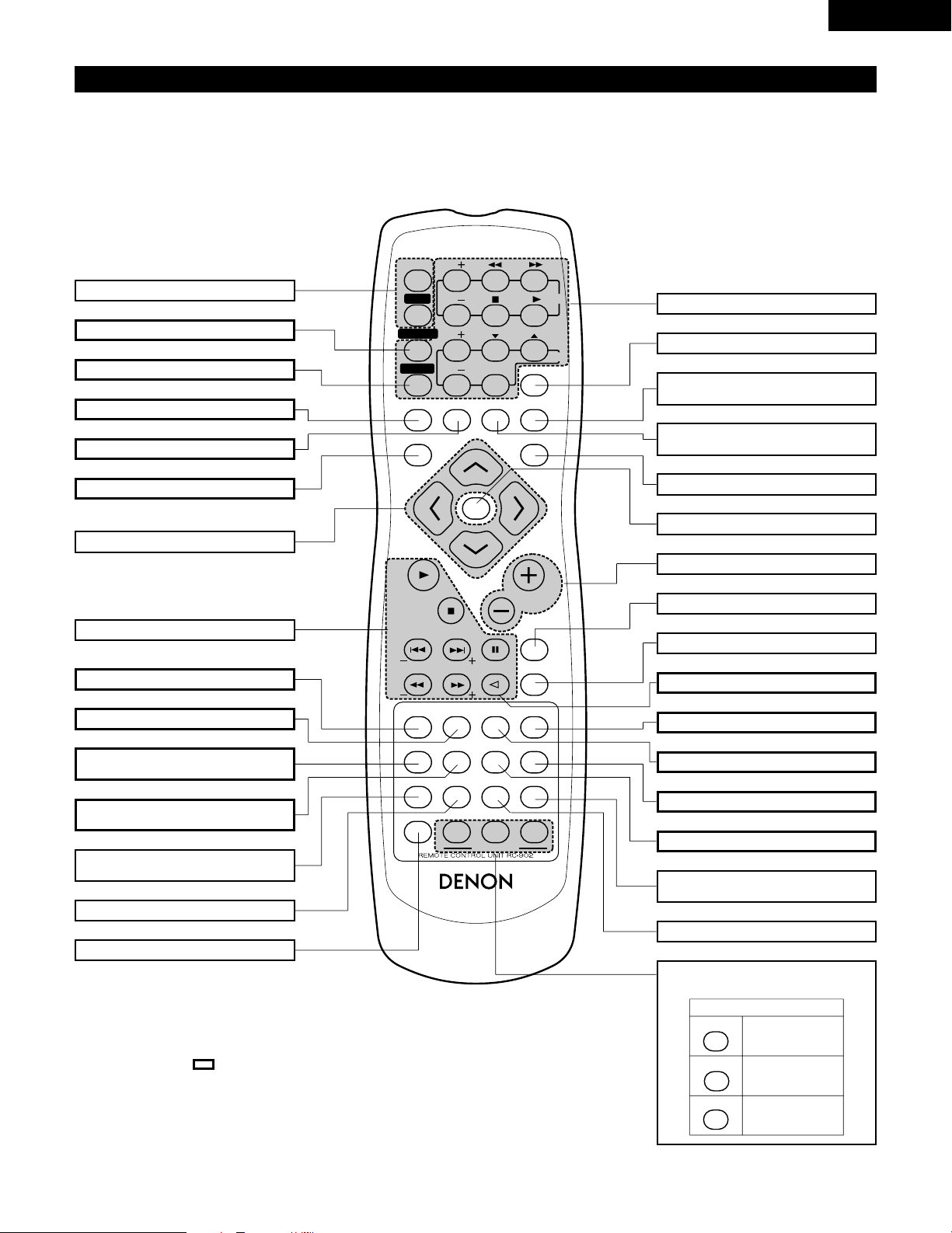
Remote control unit
• For details on the functions of these parts, refer to the pages given in parentheses ( ).
• Some of the buttons on the remote control unit have two functions.
The functions are switched using the remote control mode selector buttons (CDR/MD/TAPE, TUNER/TV/VCR and DVD). After one of these
buttons is pressed, the function will not switch until another remote control mode selector button is pressed. The remote control unit’s mode
switches as described below when the buttons are pressed.
POWER ON/OFF button ........................(31)
CLEAR button.........................................(58)
CALL button ...........................................(58)
ANGLE button ........................................(64)
RANDOM button....................................(59)
REPEAT button.......................................(56)
System buttons................................(20, 21)
SLEEP button .........................................(70)
SURROUND mode selector
button .....................................................(35)
INPUT MODE selector
button .....................................................(35)
FUNCTION selector button ....................(35)
ENTER button.........................................(22)
Main volume control buttons .................(36)
MUTE button..........................................(37)
NTSC/PAL button ...................................(10)
STATUS button .......................................(36)
TOP MENU button .................................(65)
Surround parameter button
(SURR.PARA).......................(41~45, 49~51)
SDB/TONE selector button ....................(37)
Remote control mode
selector buttons
• Buttons indicated are DVD operation buttons. These can be used when the DVD mode is
selected with the remote control mode selector buttons.
• The system buttons (*) are buttons whose functions differ according to which mode is selected
with the remote control mode selector buttons.
• Other buttons are surround amplifier operation buttons that always operate in the same way,
regardless of which mode is set with the remote control mode selector buttons.
DISPLAY button......................................(55)
RETURN button......................................(33)
MENU button .........................................(66)
Cursor buttons........................................(22)
System buttons................................(20, 21)
SUBTITLE button....................................(63)
AUDIO selector button...........................(62)
Program/direct button
(PROG/DIRECT)......................................(58)
A-B repeat button
(REPEAT A-B) .........................................(57)
Channel select button
(CH.SELECT) ..........................................(40)
Test tone button (T.TONE)......................(40)
SETUP button.........................................(22)
Remote control mode
CDR/MD/TAPE
TUNER/TV/VCR
DVD
Audio modes
AV modes
DVD modes
*
*
Page 18
18
ENGLISH
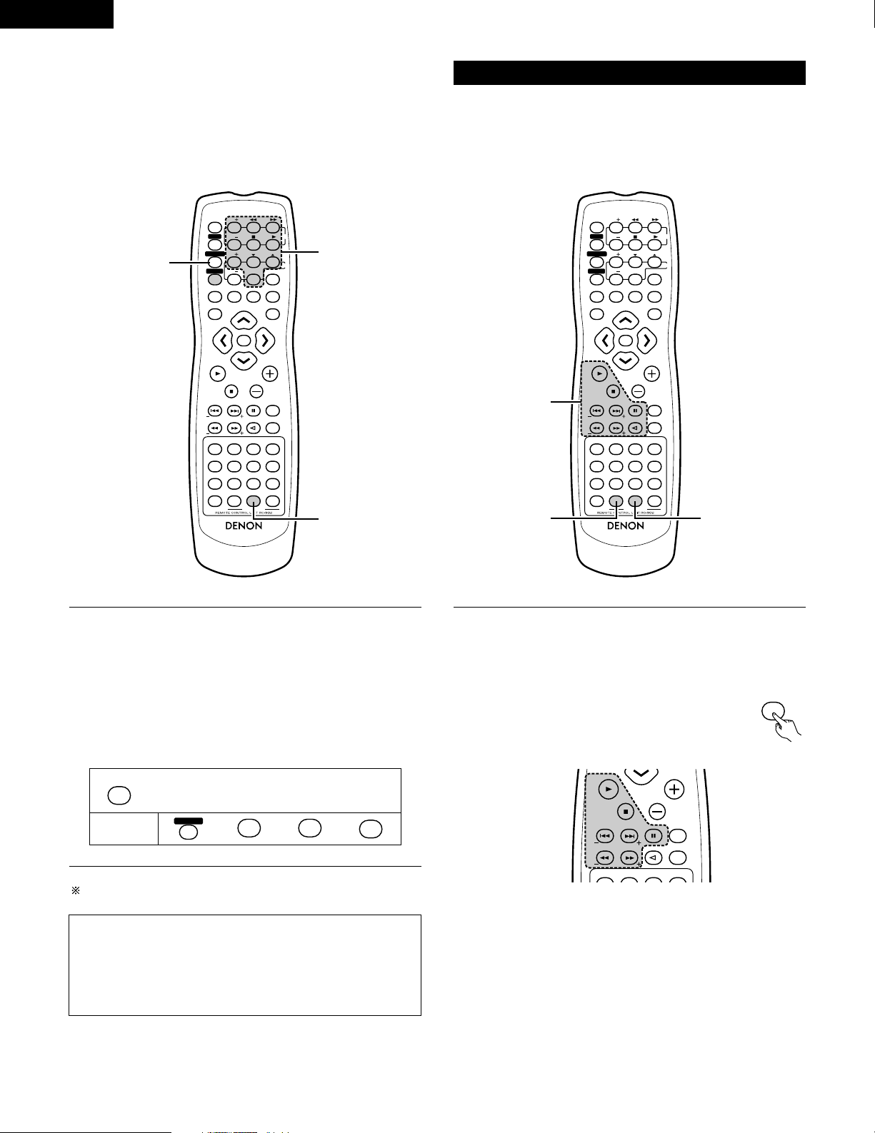
9
REMOTE CONTROL UNIT
• The included remote control unit (RC-902) can be used to operate not only this unit but other remote control compatible DENON components
as well. In addition, the memory contains the control signals for other remote control units, so it can be used to operate non-Denon remote
control compatible products.
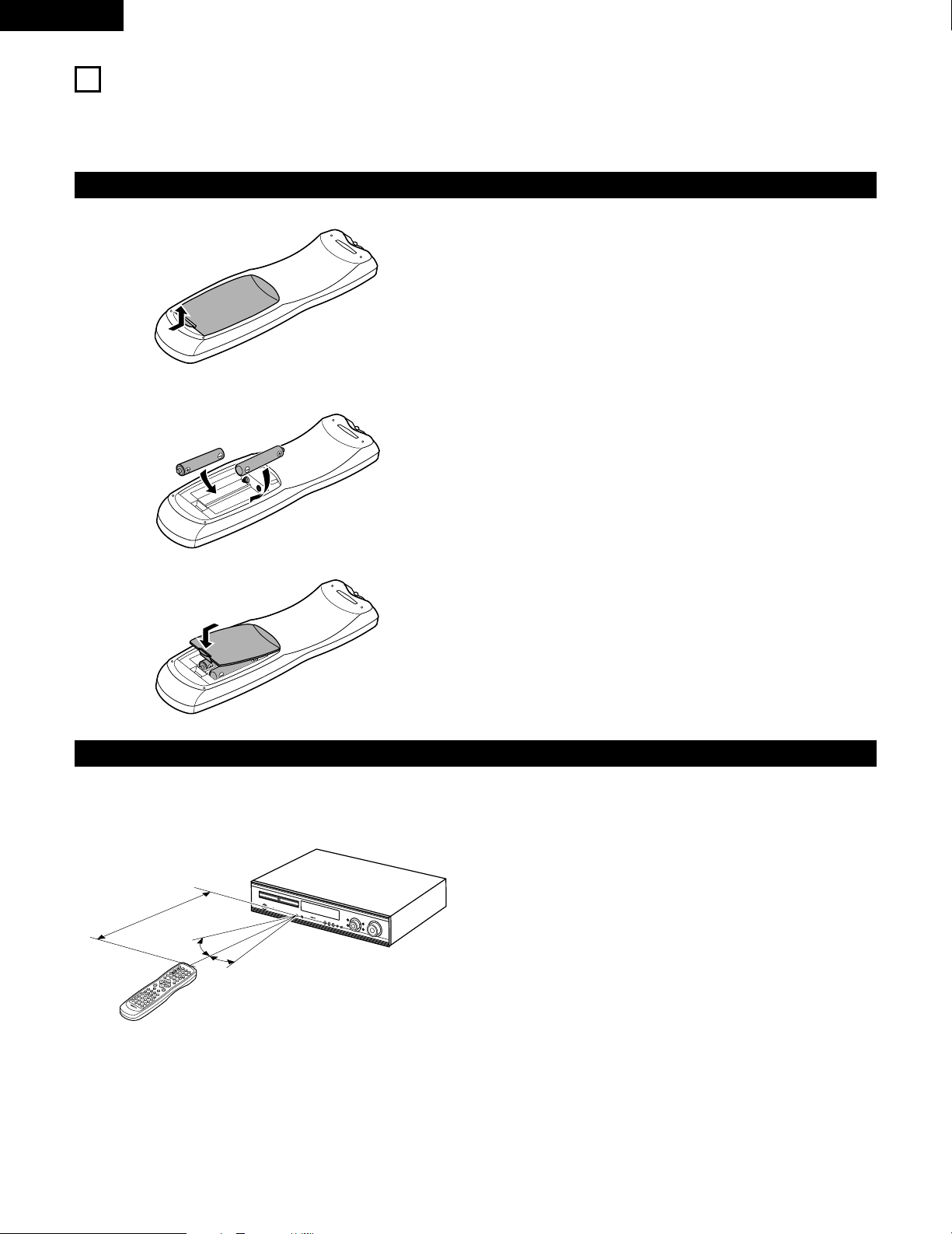
(1) Inserting the batteries
q Remove the remote control unit’s rear cover.
w Set three R6P/AA batteries in the battery compartment in the
indicated direction.
e Put the rear cover back on.
Notes on Batteries
• Use R6P/AA batteries in the remote control unit.
• The batteries should be replaced with new ones approximately
once a year, though this depends on the frequency of usage.
• Even if less than a year has passed, replace the batteries with new
ones if the set does not operate even when the remote control unit
is operated nearby the set. (The included battery is only for verifying
operation. Replace it with a new battery as soon as possible.)
• When inserting the batteries, be sure to do so in the proper
direction, following the “≈” and “√” marks in the battery
compartment.
• To prevent damage or leakage of battery fluid:
• Do not use a new battery together with an old one.
• Do not use two different types of batteries.
• Do not short-circuit, disassemble, heat or dispose of batteries in
flames.
• Remove the batteries from the remote control unit when you do
not plan to use it for an extended period of time.
• If the battery fluid should leak, carefully wipe the fluid off the inside
of the battery compartment and insert new batteries.
• When replacing the batteries, have the new batteries ready and
insert them as quickly as possible.
(2) Using the remote control unit
1
c 8 1:02:46
D
V
D
T
O
N
E
V
O
L
U
M
E
B
A
N
D
M
O
D
E
M
E
N
U
F
U
N
C
T
I
O
N
D
I
S
P
L
A
Y
R
E
T
U
R
N
I
N
P
U
T
M
O
D
E
S
U
R
R
O
U
N
D
T
O
P
M
E
N
U
S
E
T
U
P
S
D
B
/
T
O
N
E
M
U
T
E
S
U
R
R
.
P
A
R
A
S
U
B
T
I
T
L
E
A
N
G
L
E
A
U
D
I
O
S
H
I
F
T
C
H
.
S
E
L
E
C
T
C
H
T
.
T
O
N
E
T
U
P
R
O
G
/D
IR
E
C
T
R
E
P
E
A
T
A
B
R
E
P
E
A
T
R
A
N
D
O
M
D
V
D
T
V
/
V
C
R
C
H
V
O
L
S
L
E
E
P
O
N
O
F
F
R
E
M
O
C
O
N
M
O
D
E
2
3
4
5
6
8
9
0
7
1
S
T
A
T
U
S
C
D
R
/
M
D
/
T
A
P
E
T
U
N
E
R
/
T
V
/
V
C
R
V
C
R
P
O
W
E
R
T
V
P
O
W
E
R
T
V
V
C
R
N
T
S
C
/
P
A
L
E
N
T
E
R
M
U
T
E
O
N
2
3
4
5
6
C
L
E
A
R
C
A
L
L
0
M
E
M
O
P
O
W
E
R
C
H
C
H
C
H
O
F
F
1
8
9
+
1
0
7
30°
30°
• Point the remote control unit at the remote sensor on the main unit
as shown on the diagram.
• The remote control unit can be used from a straight distance of
approximately 7 meters/22 feet from the main unit, but this
distance will be shorter if there are obstacles in the way or if the
remote control unit is not pointed directly at the remote sensor.
• The remote control unit can be operated at a horizontal angle of up
to 30 degrees with respect to the remote sensor.
NOTES:
• It may be difficult to operate the remote control unit if the remote
sensor is exposed to direct sunlight or strong artificial light.
• Do not press buttons on the main unit and remote control unit
simultaneously. Doing so may result in malfunction.
• Neon signs or other devices emitting pulse-type noise nearby may
result in malfunction, so keep the set as far away from such
devices as possible.
Approx. 7m / 22 feat
Page 19
19
ENGLISH
(3) Preset memory
1
While pressing the CDR/MD/TAPE remote control mode
selector button, input the 3-digit number (“000”, “111” and
“222”) corresponding to the device you want to preset (CDR,
MD or TAPE), referring to the table below.
• Release the CDR/MD/TAPE button after inputting three
digits. This completes the presetting operation.
[1] Audio Component
• The signals of your other Denon products can be stored in the
included remote control unit’s preset memory to operate either the
CDR, MD or TAPE function.
Operation is not possible for some models.
Table 1: Combinations of Personal System Codes
Input the 3-digit number while pressing CDR/MD/TAPE.
CDR/MD/TAPE
0
1
2
0
1
2
0
1
2
CDR
MD
TAPE
This is set to CDR by factory default.
NOTE:
• Only one device (CDR, MD or TAPE) can be stored in the preset
memory.
1
Press the CALL button while pressing the TUNER/TV/VCR
remote control mode selector button, then input the threedigit number corresponding to the code of the manufacturer
of the TV whose signals you want to store, referring to the
included list of remote control unit codes.
• Release the TUNER/TV/VCR button after inputting three
digits. This completes the presetting operation.
Example: To preset to “Hitachi 074”
[2] TV
• Other makes of components can be operated by setting the preset
memory for your make of TV.
This remote control unit can be used to operate components of
other manufacturers without using the learning function by
registering the manufacturer of the components as shown on the
List of Preset Codes (attached sheet).
Operation is not possible for some models.
Press the buttons below while pressing TUNER/TV/VCR.
TUNER/TV/VCR
CALL
TV POWERTV POWER
074
HITACHI
“074”
This is set to “Hitachi 074” by factory default.
NOTE:
• Preset codes set upon shipment from the factory and when
reset.
VOLUME
ENTER
BAND
MODE
MENU
FUNCTION
DISPLAY RETURN INPUT MODE SURROUND
TOP MENU
SETUP
SDB/TONE
MUTE
SURR.PARA
SUB TITLE ANGLE
AUDIO
SHIFT
CH.SELECT
CH
T.TONE
TU
PROG/DIRECT
REPEAT A-B
REPEAT RANDOM
DVD
TV/VCR
CH
VOL
SLEEP
ON
OFF
REMOCON MODE
2
3
4
56
8
9
CLEAR
CALL
0
+10
7
1
STATUS
CDR/MD/TAPE
TUNER/TV/VCR
VCR POWERVCR POWER
TV POWERTV POWER
TV
VCR
NTSC/PAL
MEMO
POWERPOWER
CH
CH
CH
1
1
1
Page 20
20
ENGLISH
[3] VCR
• Other makes of components can be operated by setting the preset
memory for your make of video component.
This remote control unit can be used to operate components of
other manufacturers without using the learning function by
registering the manufacturer of the components as shown on the
List of Preset Codes (attached sheet).
Operation is not possible for some models.
1
Press the CLEAR button while pressing the TUNER/TV/VCR
remote control mode selector button,then input the 3-digit
number corresponding to the code of the manufacturer of the
VCR you want to store in the memory, referring to the
included table of remote control codes.
• Release the TUNER/TV/VCR button after inputting three
digits. This completes the presetting operation.
Example: To preset to Hitachi “072”
Press the buttons below while pressing TUNER/TV/VCR.
TUNER/TV/VCR
CLEAR
VCR POWERVCR POWER
0
7
2
HITACHI
“072”
This is set to Hitachi “072” by factory default.
NOTE:
• Some models and years of manufacture of components of the
manufacturers listed on the List of Preset Codes cannot be used.
• The unit is equipped with several types of remote control codes
which depend on the manufacturer. If there is no operation,
please change the preset code (a 3-digit number) and try again.
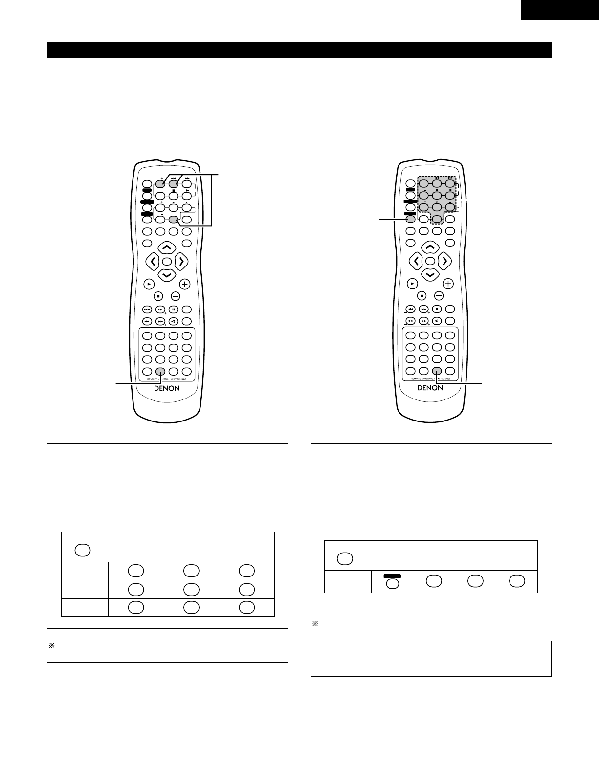
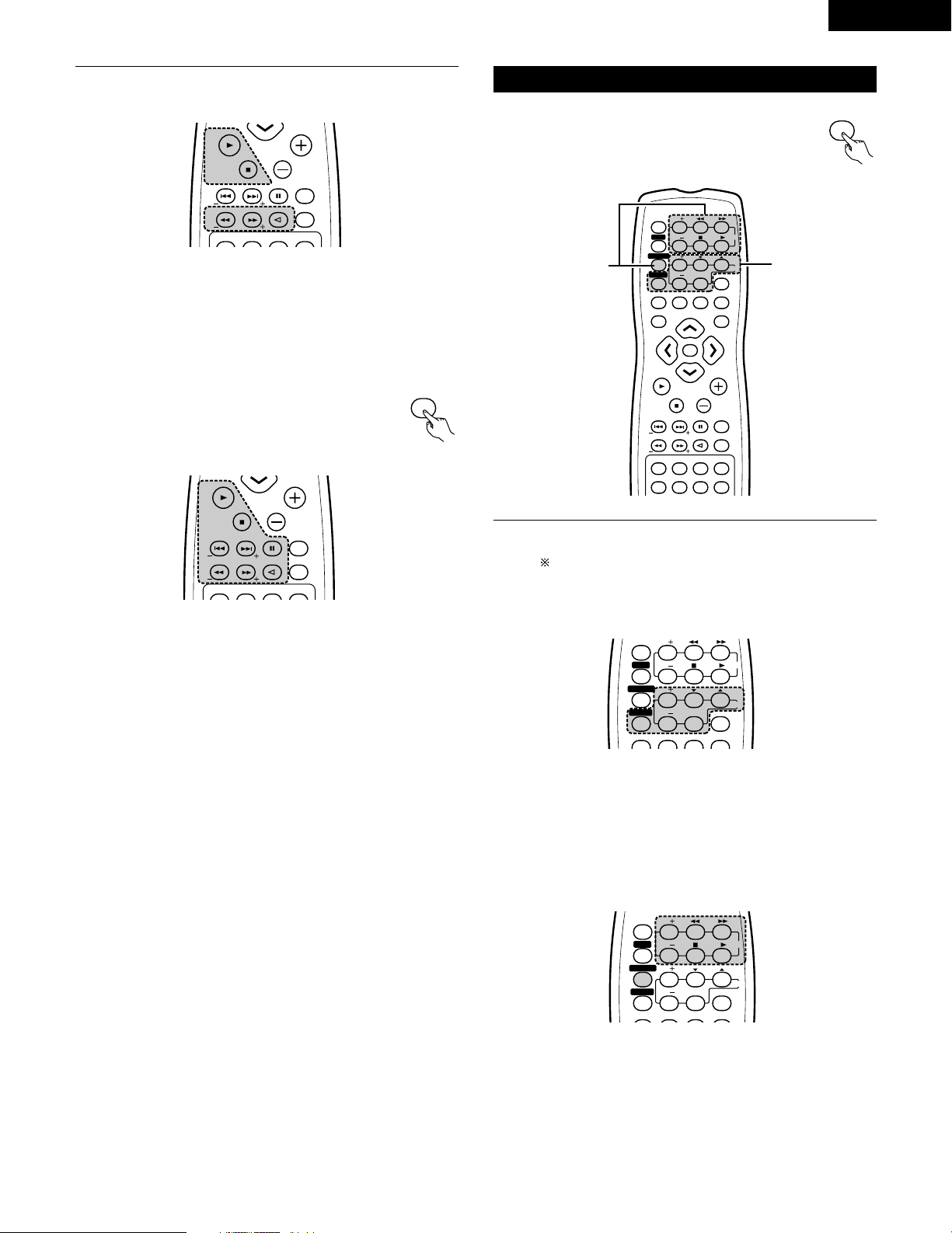
(4) Operating DENON audio components
1
DENON remote-controllable audio components can be
controlled using this unit’s remote control unit.
Note that some components, however, cannot be operated
with this remote control unit.
Before operating the remote control unit!
Be sure to set the audio device mode using the
remote control mode selector buttons.
a. For CDR recorder or MD recorder
6,7 : Manual search (reverse and forward)
2 : Stop
1 :Play
8,9 : Auto search
3 : Pause
VOLUME
ENTER
BAND
MODE
MENU
FUNCTION
DISPLAY RETURN INPUT MODE SURROUND
TOP MENU
SETUP
SDB/TONE
MUTE
SURR.PARA
SUB TITLE ANGLE
AUDIO
SHIFT
CH.SELECT
CH
T.TONE
TU
PROG/DIRECT
REPEAT A-B
REPEAT RANDOM
DVD
TV/VCR
CH
VOL
SLEEP
ON
OFF
REMOCON MODE
2
3
4
56
8
9
CLEAR
CALL
0
+10
7
1
STATUS
CDR/MD/TAPE
TUNER/TV/VCR
VCR POWERVCR POWER
TV POWERTV POWER
TV
VCR
NTSC/PAL
MEMO
POWERPOWER
CH
CH
CH
1
1
1
VOLUME
ENTER
BAND
MODE
MENU
FUNCTION
DISPLAY RETURN INPUT MODE SURROUND
TOP MENU
SETUP
SDB/TONE
MUTE
SURR.PARA
SUB TITLE ANGLE
AUDIO
SHIFT
CH.SELECT
CH
T.TONE
TU
PROG/DIRECT
REPEAT A-B
REPEAT RANDOM
DVD
TV/VCR
CH
VOL
SLEEP
ON
OFF
REMOCON MODE
2
3
4
56
8
9
CLEAR
CALL
0
+10
7
1
STATUS
CDR/MD/TAPE
TUNER/TV/VCR
VCR POWERVCR POWER
TV POWERTV POWER
TV
VCR
NTSC/PAL
MEMO
POWERPOWER
CH
CH
CH
1-a,b
1
1-c,z
CDR/MD/TAPE
VOLUME
BAND
MODE
TOP MENU
MUTE
SUB TITLE ANGLE
AUDIO
SHIFT
CH
TU
STATUS
VCR POWER
TV POWER
NTSC/PAL
MEMO
POWER
Page 21
21
ENGLISH
1
b. For tape deck (TAPE)
6 : Rewind
7 : Fast-forward
2 : Stop
1 : Forward Play
: : Reverse Play
Before operating the remote control unit!
Be sure to press the proper remote control mode
selector button to set the remote control unit to
the AV mode.
c. For TUNER
SHIFT : Switch preset channel range
CHANNEL : Preset channel up/down
(+, –)
TUNING (+, –) : Tuning up/down
BAND : Switch between AM and FM bands
MODE : Switch between AUTO and MONO
MEMORY : Preset memory
(5)
Operating a video component stored in the preset memory
Before operating the remote control unit!
Be sure to press the proper remote control mode
selector button to set the remote control unit to
the AV mode.
1
Operate the TV or VCR.
• For details, refer to the component’s operating instructions.
Some models cannot be operated with this remote control
unit.
a. For monitor TV
TV POWER : Power on/off
CHANNEL : Switch channel
(+, –)
VOLUME : Volume up/down
(
•,ª)
TV/VCR : Switch between TV and VCR
b. For video deck (VCR)
VCR POWER : Power on/off
CHANNEL : Switch channel
(+, –)
6,7 : Forward and reverse
1 :Play
2 : Stop
VOLUME
BAND
MODE
TOP MENU
MUTE
SUB TITLE ANGLE
AUDIO
SHIFT
CH
TU
STATUS
VCR POWER
TV POWER
NTSC/PAL
MEMO
POWER
VOLUME
BAND
MODE
TOP MENU
MUTE
SUB TITLE ANGLE
AUDIO
SHIFT
CH
TU
STATUS
VCR POWER
TV POWER
NTSC/PAL
MEMO
POWER
TUNER/TV/VCR
TUNER/TV/VCR
VOLUME
ENTER
BAND
MODE
MENU
FUNCTION
DISPLAY RETURN INPUT MODE SURROUND
TOP MENU
MUTE
SUB TITLE ANGLE
AUDIO
SHIFT
CH
TU
PROG/DIRECT
REPEAT A-B
REPEAT RANDOM
TV/VCR
CH
VOL
SLEEP
ON
OFF
2
3
4
56
8
9
CLEAR
CALL
0
+10
7
1
STATUS
VCR POWERVCR POWER
TV POWERTV POWER
TV
VCR
NTSC/PAL
MEMO
POWERPOWER
CH
CH
CH
1-a
1-b
DISPLAY RETURN INPUT MODE SURROUND
TV/VCR
CH
VOL
SLEEP
ON
OFF
2
3
4
56
8
9
CLEAR
CALL
0
+10
7
1
VCR POWER
TV POWERTV POWER
TV
VCR
POWER
CH
CH
CH
DISPLAY RETURN INPUT MODE SURROUND
TV/VCR
CH
VOL
SLEEP
ON
OFF
2
3
4
56
8
9
CLEAR
CALL
0
+10
7
1
VCR POWER
TV POWER
TV
VCR
POWER
CH
CH
CH
Page 22
22
ENGLISH
REMOTECONTROLUNITRC-902
VOLUME
ENTER
BAND
MODE
MENU
DISPLAY RETURN INPUT MODE SURROUND
TOP MENU
SETUP
SDB/TONE
MUTE
SURR.PARA
SUB TITLE ANGLE
AUDIO
SHIFT
CH.SELECT
CH
T.TONE
TU
PROG/DIRECT
REPEAT A-B
REPEAT RANDOM
DVD
REMOCON MODE
STATUS
CDR/MD/TAPE
TUNER/TV/VCR
VCR POWER
TV POWER
NTSC/PAL
MEMO
POWER
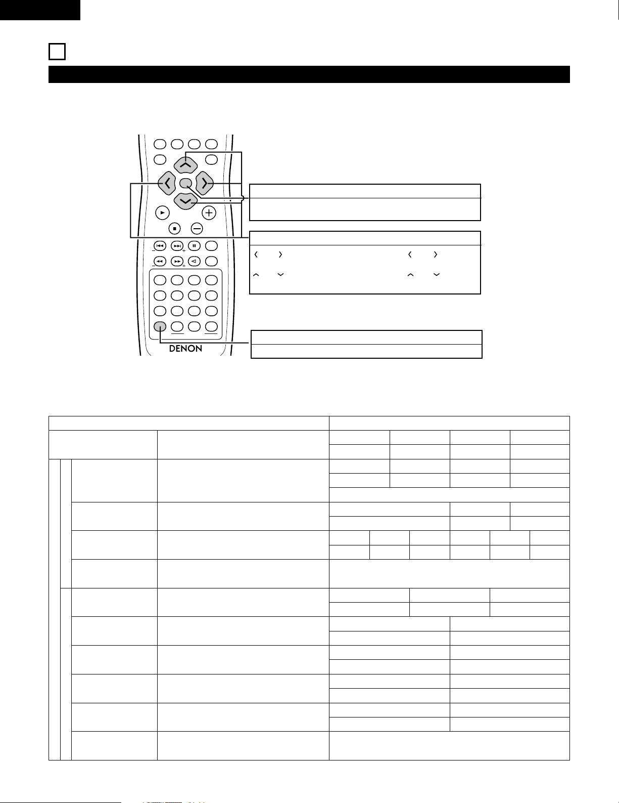
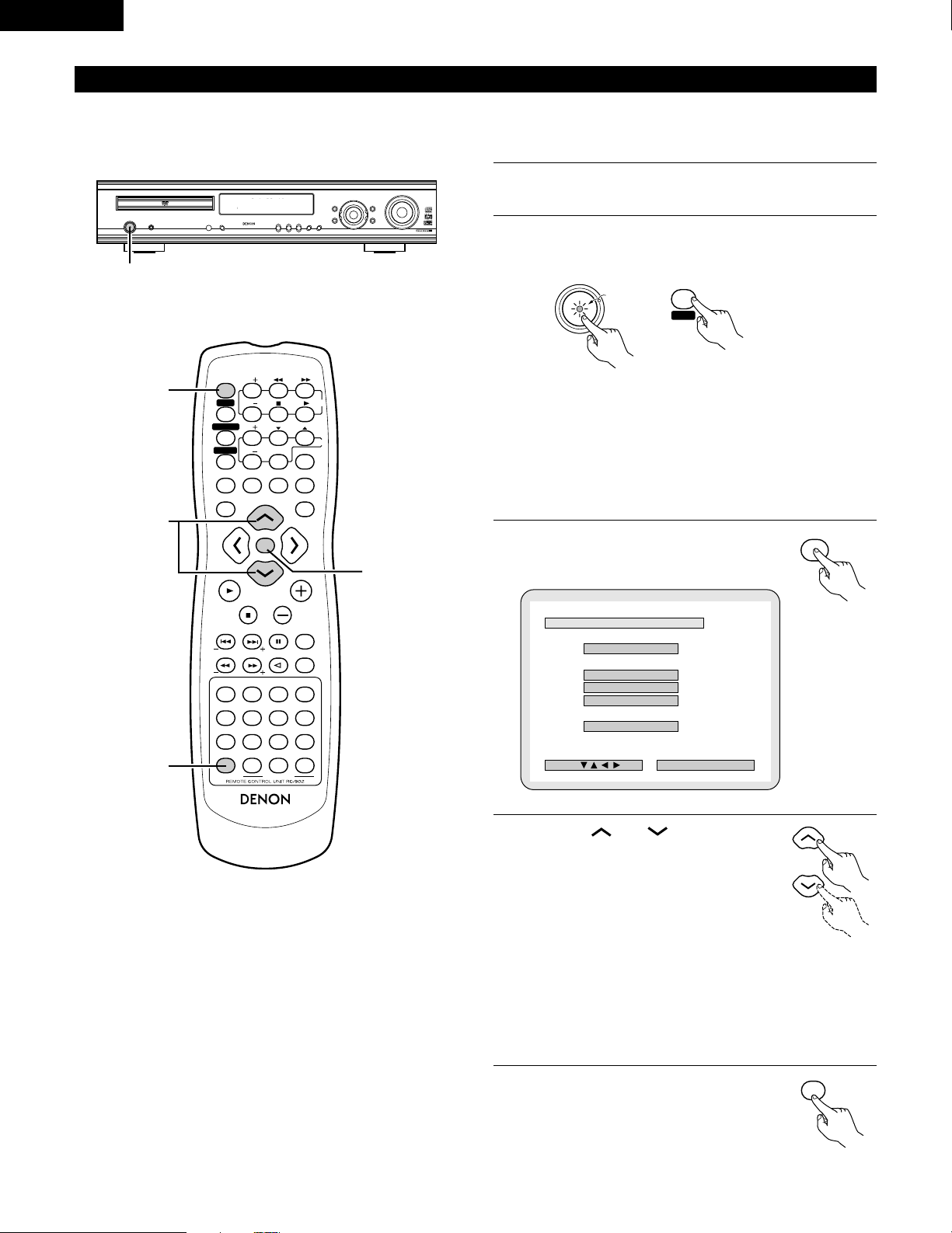
10
SETTING UP THE SYSTEM
• Once all connections with other AV components have been completed as described in “CONNECTIONS” (see pages 8 to 15), make the various
settings described below on the monitor screen using the ADV-700’s on-screen display function.
• Use the following buttons to set up the system:
System setup items and default values (set upon shipment from the factory)
Setup
Quick system
Speaker Configuration
Delay Time
Channel Level
DVD auto power off setting
Disc Setup
OSD Setup
Video Setup
Audio Setup
Ratings
Other Setup
Input the combination of speakers in your system and
their corresponding sizes (SMALL for regular speakers,
LARGE for full-size, full-range) to automatically set the
composition of the signals output from the speakers and the
frequency response.
This parameter is for optimizing the timing with which the
audio signals are produced from the speakers and subwoofer
according to the listening position.
At the listening position, listen to the test tones output
from the different speakers and set so that the playback
level from the different speakers is equal.
The power automatically switches to standby if no
operation is performed for 30 minutes while in the stop
mode with the function set to DVD.
Set the audio language, subtitle language and disc menu
language for when playing discs.
Set the on-screen display language and wallpaper for the
setup and operation screens.
Set the screen size and video system for the TV being used.
Set the digital audio signal format and the linear PCM
sampling frequency and bit conversion.
Make the playback restriction setting for DVDs with
restricted viewing and set the password required for
changing the setting.
Make the closed caption setting for DVDs. (A commercially
available decoder is required to display the closed captions.)
Setup
Default settings
Front Sp.
Small 9ft (2.7m)
Front Sp.
Small
Front & Subwoofer Center
8ft (2.4m)
Surround
7ft (2.1m)9ft (2.7m)
Front L
0 dB
Dialog Subtitle Disc Menu
English
OSD Language Wall Paper
English
TV Aspect
4 : 3 PS
Digital Out
Normal
Rating Level
No Limit
Closed Caption : OFF
Blue
TV Type
NTSC
LPCM Select
OFF
Pass Word Change
0000 (Default)
OFF English
power does not turn off automatically
Center
0 dB
Front R
0 dB
Surround R
0 dB
Surround L
0 dB
Sub Woofer
0 dB
Center Sp.
Small
Surround Sp. A / B
Small
Sub Woofer
Ye s
Sw Freq. = 120 Hz / SW mode = None
Center Sp.
Small 8ft (2.4m)
Surround Sp.
Small 7ft (2.1m)
Sub Woofer
Yes 9ft (2.7m)
System Setup
DVD Setup
(1) System setup items
SYSTEM SETUP button
Press this to display the system setup menu.
ENTER button
Press this to switch the display.
Also use this button to complete the setting.
CURSOR buttons
and
:Use these to move the cursors (
and
) to the
left
and right
on the screen.
and
:Use these to move the cursors (
and
) to the up
and down on the screen.
Page 23
23
ENGLISH
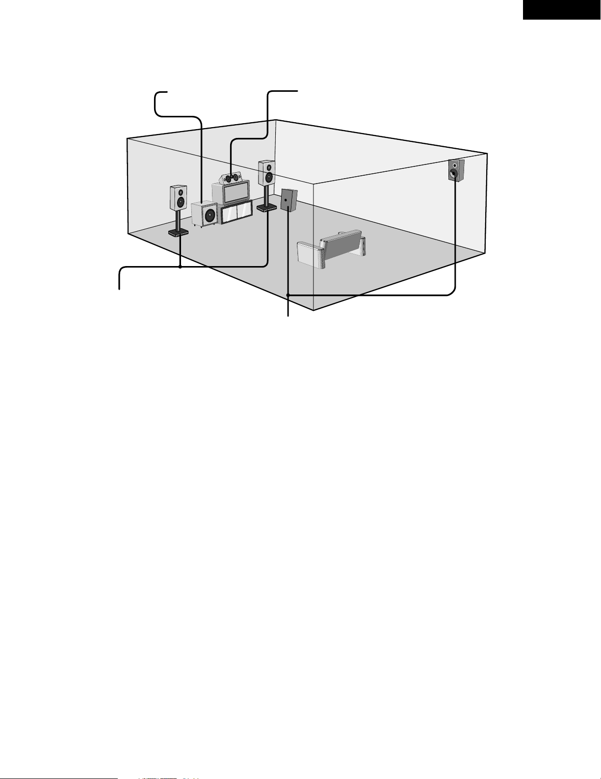
• Speaker system layout
Basic system layout
• The following is an example of the basic layout for a system consisting of eight speaker systems and a television monitor:
Subwoofer
Center speaker system
Surround speaker systems
Front speaker systems
Set these at the sides of the TV or screen with
their front surfaces as flush with the front of the
screen as possible.
Page 24
24
ENGLISH
(2) Before setting up the system
• This section describes surround-related setup operations.
For DVD-related setup operations, see page 71.
• The setup operations cannot be performed while discs are playing. Set the stop mode first.
1
Refer to “CONNECTIONS” (pages 8 to 15) and check that all
connections are correct.
2
Turn on the power.
Press the POWER switch (button).
ON / STANDBY
ON
POWERPOWER
When pressed, the power turns on and the display lights. The sound
is muted for several seconds, after which the unit operates normally.
When pressed again, the power turns off, the standby mode is set
and the display turns off.
Whenever the ON/STANDBY button is in the STANDBY state, the
apparatus is still connected on AC line voltage. Please be sure to
unplug the cord when you leave home for, say, a vacation.
3
Press the SETUP button.
4
Use the and cursor buttons
on the remote control unit to select the
setting menu.
• There are three types of setup
menus.
B Quick system settings: To switch between the 2- and 5.1-channel
modes
B System setting changes: Detailed settings of the AV system
function
B DVD setting changes: Detailed settings of the DVD function
5
Press the ENTER button to display
the setting screen of the respective
menu.
1
c 8 1:02:46
DVD
TONE
2
VOLUME
ENTER
BAND
MODE
MENU
FUNCTION
DISPLAY RETURN INPUT MODE SURROUND
TOP MENU
SETUP
SDB/TONE
MUTE
SURR.PARA
SUB TITLE ANGLE
AUDIO
SHIFT
CH.SELECT
CH
T.TONE
TU
PROG/DIRECT
REPEAT A-B
REPEAT RANDOM
DVD
TV/VCR
CH
VOL
SLEEP
ON
OFF
REMOCON MODE
2
3
4
56
8
9
CLEAR
CALL
0
+10
7
1
STATUS
CDR/MD/TAPE
TUNER/TV/VCR
VCR POWER
TV POWER
TV
VCR
NTSC/PAL
MEMO
POWER
CH
CH
CH
5
3
2
4
B
QUICK SETUPQUICK SETUP
<
ADVANCED SETUPADVANCED SETUP
>
SYSTEM SETUPSYSTEM SETUP
DVD SETUPDVD SETUP
>EXIT SETUPEXIT SETUP
DEC I SI ON: ENTER BUTTON
SETUP MENU
SELECT :
SETUP
ENTER
Light
(green)
Remote control unit
Remote control unit
Remote control unit
Main unit Remote control unit
Page 25
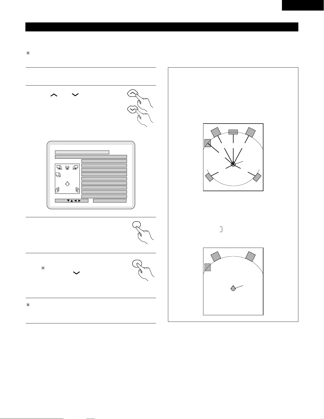
25
ENGLISH
(3) Quick system settings (to switch between the 2- and 5.1-channel modes)
• The ADV-700 is preset with Quick System settings for a 5.1-channel surround system using five small speakers and a subwoofer or a 2-channel
virtual system using two large front speakers with or without a subwoofer.
• The system settings can be made and the ADV-700 used for playing discs simply by choosing the speaker systems you are using.
See “(4) System setting changes” (pages 26 to 30 when using speaker systems other than the ones described below or if you wish to change
the settings.
1
At the setup screen, select “QUICK SETUP”, then press the
ENTER button. (See page 24.)
2
At the quick system setting screen, use
the and cursor buttons to
select the speaker system you are
using.
• The selected speaker name is indicated in
yellow.
• The setting is displayed.
3
Press the ENTER button to enter the setting.
• The setup screen reappears.
4
Press the SETUP button to quit the
setup mode.
You can also quit the setup mode
by using the cursor button
at the setup screen to display
“Quit setup” in yellow then
pressing the ENTER button.
To change the settings
At the setup screen, select “SYSTEM SETUP” from
“<ADVANCED SETUP>”.
Quick system setting parameters
5.1-channel surround system
Low frequency Delay time
playback ability (distance)
Front : Small 9ft (2.7m): L2
Center : Small 8ft (2.4m): L1
Surround : Small 7ft (2.1m): L3
Subwoofer : Yes 9ft (2.7m): L2
2-channel virtual system
Front : Large (2 channels only)
2-channel virtual + subwoofer system
Front : Large
Placed at equal distances
Subwoofer : Yes
B
SELECT YOUR SPEAKER SYSTEMSELECT YOUR SPEAKER SYSTEM
EXITEXIT
5.1CH SURROUND5.1CH SURROUND
2CH VIRTUAL2CH VIRTUAL
2CH VIRTUAL&SW2CH VIRTUAL&SW
<
SETUP VALUESSETUP VALUES
>
FRONTFRONT SMALLSMALL 9 f t9 f t
CENTER CENTER SMALLSMALL 8 f t8 f t
SURROUNDSURROUND SMALL SMALL 7 f t7 f t
SUBWOOFERSUBWOOFER YESYES 9 f t9 f t
DEC I SI ON: ENTER BUTTON
QUICK SETUP MENU
SELECT :
ENTER
SETUP
L1L2 L2
L2
L3 L3
Front L
Subwoofer
Center Front R
Surround L Surround R
Listening
position
Front L Front R
Subwoofer
Listening
position
Remote control unit
Remote control unit
Remote control unit
Page 26
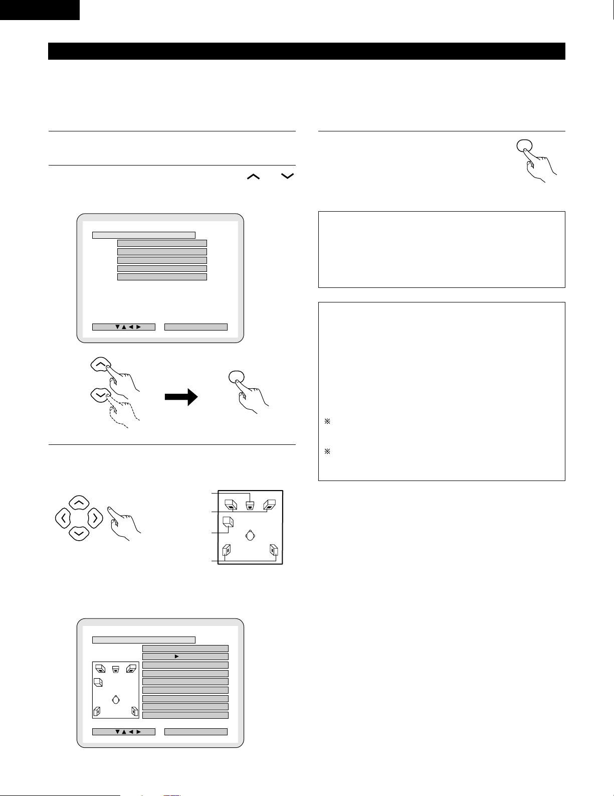
26
ENGLISH
(4) System setting changes
• The quick system settings and factory default settings are changed at the system setting change menu.
• The settings are stored in the memory until they are next changed, even when the power is turned off.
1
At the SETUP MENU, select “SYSTEM SETUP” and press
the ENTER button
2
At the SYSTEM SETUP MENU screen, use the and
cursor buttons to select the speaker system you are using.
“SPEAKER CONFIGURATION” and press the ENTER button.
3
Set whether or not speakers are connected and, if so, their
size parameters.
4
Enter the setting.
• The Setup Menu reappears.
[1] Setting the type of speakers
• The composition of the signals output from the different channels and the frequency response are adjusted automatically according to the
combination of speakers actually being used.
NOTE:
• Select “Large” or “Small” not according to the actual size of the
speaker but according to the speaker’s capacity for playing low
frequency (approximately 100 Hz and below) signals. If you do
not know, try comparing the sound at both settings (setting the
volume to a level low enough so as not to damage the speakers)
to determine the proper setting.
Parameters
Large…… Select this when using speakers that can fully reproduce
low sounds of below 100 Hz.
Small…… Select this when using speakers that do not provide
sufficient volume for playing low frequencies of 100 Hz
and less. When this setting is made, frequencies below
the frequency set at the subwoofer frequency setting
are assigned to the subwoofer.
None…… Select this when no speakers are installed.
Yes/No…. Select “Ye s ” when a subwoofer is installed, “No” when
a subwoofer is not installed.
If the subwoofer has sufficient low frequency playback capacity,
good sound can be achieved even when “Small” is set for the
front, center and surround speakers.
For the majority of speaker system configurations, using the
SMALL setting for all five main speakers and Subwooofer On
with a connected subwoofer will yield the best results.
B
SPEAKER CONFIGURATIONSPEAKER CONFIGURATION
DELAY TIMEDELAY TIME
CHANNEL LEVELCHANNEL LEVEL
DVDDVD AUTOAUTO POWERPOWER OFFOFF
>SETUPSETUP MENUMENU
DEC I SI ON: ENTER BUTTON
SYSTEM SETUP MENU
SELECT :
ENTER
B
FRONTFRONT SP. :SP. :
CENTERCENTER SP. :SP. :
LARGELARGE SMALLSMALL NONENONE
SURROUNDSURROUND SP. :SP. :
LARGELARGE SMALLSMALL NONENONE
SUBWOOFERSUBWOOFER : YESYES NONO
SW SW FREQ.FREQ. : 120Hz120Hz
SW MODE SW MODE : LFELFE LFE LFE
+ +
MAINMAIN
FINISH: ENTER BUTTON
SPEAKER CONFIGURATION
SELECT :
LARGELARGE SMALLSMALL
ENTER
Remote control unit
• The item to be set is displayed in yellow, and the values of the other
items are displayed in green.
CENTER SPEAKER
FRONT SPEAKERS
SUB WOOFER
SURROUND
SPEAKEERS
Remote control unit Remote control unit
Remote control unit
Page 27

27
ENGLISH
Subwoofer (SW FREQ.) frequency
• For the subwoofer frequency at the speaker setting screen, set
the bass crossover frequency for playback from the subwoofer.
• Select “80 Hz”, “120 Hz”, “180 Hz” or “240 Hz” (-6 dB for
each). Bass sound below these frequencies is played from the
subwoofer.
(This is set to “120 Hz” by factory default.)
Assignment of low frequencies
• In the Dolby Digital, Dolby Pro Logic II, DTS, and virtual surround
modes, the low frequency signals for channels whose speaker
settings are set to “Small” are assigned to the subwoofer. The
low frequencies of channels set to “Large” are played from
those channels.
(If set to “120 Hz”, channels set to “Small” play sounds of 120
Hz and greater, while bass frequencies of under 120 Hz are
played from the subwoofer.)
• In surround modes other than the ones listed above, low
frequencies below the frequency set at the subwoofer frequency
setting are played from the subwoofer regardless of whether the
speakers are set to “Large” or “Small”.
• Set the subwoofer frequency according to the low frequency
playback abilities of your speakers and subwoofer.
Subwoofer mode
• The subwoofer mode setting is only valid when “LARGE” is set
for the front speakers and “YES” is set for the subwoofer in the
“SPEAKER CONFIGURATION” settings.
• When the “LFE+MAIN” playback mode is selected, the low
frequency signal range of channels set to “LARGE” are produced
simultaneously from those channels and the subwoofer channel.
In this playback mode, the low frequency range expand more
uniformly through the room, but depending on the size and shape
of the room, interference may result in a decrease of the actual
volume of the low frequency range.
• Selection of the “LFE ” play mode will play the low frequency
signal range of the channel selected with “LARGE” from that
channel only. Therefore, the low frequency signal range that are
played from the subwoofer channel are only the low frequency
signal range of LFE (only during Dolby Digital or DTS signal
playback) and the channel specified as “SMALL” in the setup
menu.
• Select the play mode that provides bass reproduction with body.
• When the subwoofer is set to “YES”, bass sound is output from
the subwoofer regardless of the subwoofer mode setting in
surround modes other than Dolby/DTS.
Page 28
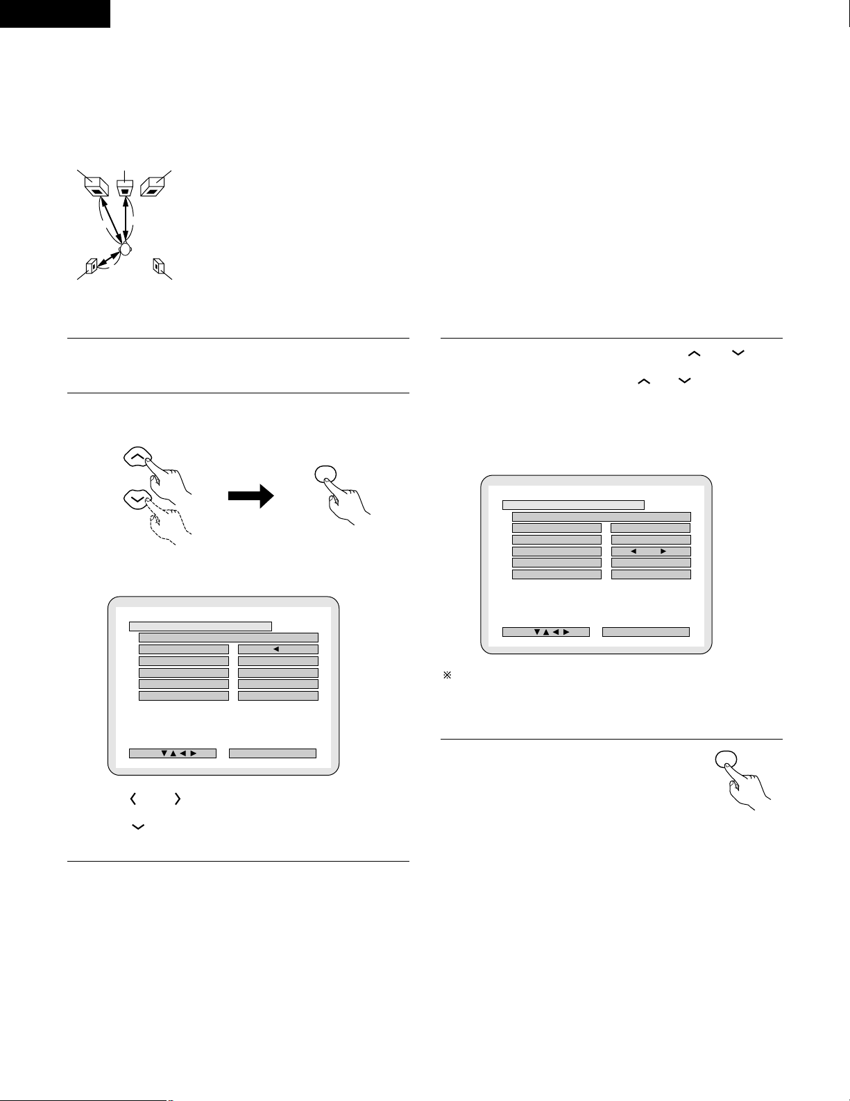
28
ENGLISH
[2] Setting the speaker distance
• Input the distances from the listening position to the speakers and
set the surround delay time.
• The default settings below are set upon shipment from the factory.
Preparations:
Measure the distances from the listening position to the speakers (L1
to L3 on the diagram at the right).
1
To perform these operations from places other than the
system setting change menu, see page 26.
2
At the SYSTEM SETUP MENU select “DELAY TIME”.
• Switch to the DELAY TIME screen.
3
When “YES” is selected for “DEFAULT”, the delay times for
the various speakers are set to the default values.
4
Select the speaker to be set using the and cursor
buttons, then setting the distance between the speakers and
the listening position using the and cursor buttons.
• Set the distance between the center speaker and listening position.
The distance changes in units of 1 foot (0.1 meters) each time the
button is pressed. Select the value closest to the measured
distance.
5
Enter the setting.
• The SYSTEM SETUP MENU reappears.
FRFL
SRSL
Center
L2
L1
L3
B
9 f t 9 f t
8 f t 8 f t
7 f t 7 f t
FINISH: ENTER BUTTON
DELAY TIME
SELECT :
METERSMETERS FEETFEET
SET THE DISTANCE TO EACH SPEAKERSSET THE DISTANCE TO EACH SPEAKERS
DEFAULTDEFAULT
FRONT&SWFRONT&SW
CENTERCENTER
SURROUNDSURROUND
UNITUNIT
B
8 f t8 f t
7 f t7 f t
FINISH: ENTER BUTTON
DELAY TIME
SELECT :
METERSMETERS FEETFEET
SET THE DISTANCE TO EACH SPEAKERSSET THE DISTANCE TO EACH SPEAKERS
DEFAULTDEFAULT
FRONT&SWFRONT&SW
CENTERCENTER
SURROUNDSURROUND
UNITUNIT
9 f t9 f t
ENTER
L1: Distance from center speaker to
listening position
L2: Distance from front speakers to
listening position
L3
: Distance from surround speaker to
listening position
ENTER
• Use the and cursor buttons to select the distance unit,
“METERS” or “FEET”.
Press the cursor button to proceed to the next step if you do
not wish to change this.
B YES: FRONT & SW / 9ft
CENTER / 8ft
SURROUND / 7ft
B NO: The current settings are used.
The difference of the distances set for the different speakers must
be no greater than 10 ft (3.0 m).
If an inapplicable distance is set, “CAUTION: INVALID DISTANCE”
is displayed. Change the speaker position and reset.
Listening
position
Remote control unit Remote control unit
Remote control unit
Page 29
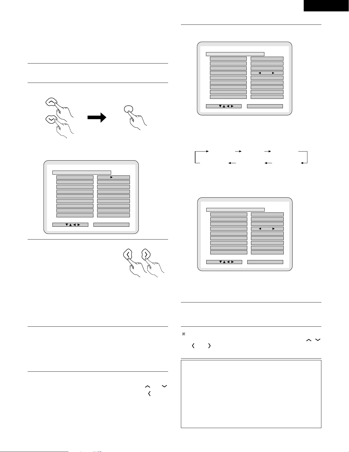
29
ENGLISH
[3] Setting the channel level
• Use this setting to adjust so that the playback level between the
different channels is equal.
• From the listening position, listen to the test tones produced from
the speakers to adjust the level.
• The level can also be adjusted directly from the remote control unit.
(For details, see page 40.)
1
To perform these operations from places other than the
system setting change menu, see page 26.
2
At the SYSTEM SETUP MENU select “CHANNEL LEVEL”.
• Switch to the CHANNEL LEVEL screen.
3
Select “TEST TONE MODE”.
• Select the mode.
Select “AUTO” or “MANUAL”.
• AUTO: Adjust the level while listening to the test tones produced
automatically from the different speakers.
• MANUAL: Select the speaker from which you want to produce the
test tone to adjust the level.
4
If “YES” is selected at “LEVEL CLEAR”, the level settings for
all the speakers are set to 0 dB.
B “YES” : The levels of the different speakers are all set to 0dB.
B “NO” : The speakers stay at their currently set levels.
5
Adjusting the channel levels in the “test tone” mode
• Set the “TEST TONE START” mode using the and
cursor buttons, then select “YES” with the cursor
button to output test tones.
6
q When “AUTO” is selected in the “TEST TONE MODE”
• Test tones are automatically emitted from the different speakers.
• The test tones are emitted from the different speakers in the
following order, at 4-second intervals the first time and second
time around, 2-second intervals the third time around and on:
•
Use the CURSOR buttons to adjust all the speakers to the same volume.
•
The volume can be adjusted between –12 dB and +12 dB in units of 1 dB.
w When the “MANUAL” mode is selected
• Use the CURSOR left and right to select the speaker for which you
want to output test tones, then use the CURSOR up and down to
adjust so that the volume of the test tones from the various
speakers is the same.
7
After the above settings are completed, press the ENTER
button.
• The “SYSTEM SETUP MENU” screen reappears.
To cancel the setting after adjusting
Display the channel level adjustment screen, then use the ,
, and cursor buttons to select “LEVEL CLEAR” and
“YES”. The level settings for all the speakers are set to 0 dB.
NOTE:
• When you adjust the channel levels while in the SYSTEM SETUP
CHANNEL LEVEL mode, the channel level adjustments made
will affect ALL surround modes. Consider this mode a Master
Channel Level adjustment mode.
• After you have completed the SYSTEM SETUP CHANNEL LEVEL
adjustments, you can then activate the individual surround
modes and adjust channel levels that will be remembered for
each of those modes. Then, whenever you activate a particular
surround sound mode, your preferred channel level adjustments
for just that mode will be recalled. Check the instructions for
adjusting channel levels within each surround mode on page 40.
B
0 d B0 d B
0 d B0 d B
0 d B0 d B
0 d B0 d B
0 d B0 d B
FINISH: ENTER BUTTON
CHANNEL LEVEL
SELECT :
AUTOAUTO MANUALMANUAL
TEST TONE MODETEST TONE MODE
TEST TONE STARTTEST TONE START
FRONT LFRONT L
CENTERCENTER
FRONT RFRONT R
SURROUND RSURROUND R
SURROUND LSURROUND L
SUBWOOFERSUBWOOFER
LEVEL CLEARLEVEL CLEAR
0 d B0 d B
B
YESYES
0 d B0 d B
0 d B0 d B
0 d B0 d B
0 d B0 d B
0 d B0 d B
FINISH: ENTER BUTTON
CHANNEL LEVEL
SELECT :
AUTOAUTO MANUALMANUAL
TEST TONE MODETEST TONE MODE
TEST TONE STARTTEST TONE START
FRONT LFRONT L
CENTERCENTER
FRONT RFRONT R
SURROUND RSURROUND R
SURROUND LSURROUND L
SUBWOOFERSUBWOOFER
LEVEL CLEARLEVEL CLEAR
+ +
1 0 d B1 0 d B
B
YESYES
0 d B0 d B
0 d B0 d B
0 d B0 d B
0 d B0 d B
0 d B0 d B
FINISH: ENTER BUTTON
CHANNEL LEVEL
SELECT :
AUTO AUTO MANUALMANUAL
TEST TONE MODETEST TONE MODE
TEST TONE STARTTEST TONE START
FRONT LFRONT L
CENTERCENTER
FRONT RFRONT R
SURROUND RSURROUND R
SURROUND LSURROUND L
SUBWOOFERSUBWOOFER
LEVEL CLEARLEVEL CLEAR
+ +
1 0 d B1 0 d B
ENTER
Front L Center Front R
Surround RSurround LSubwoofer
Remote control unit Remote control unit
Remote control unit
Page 30
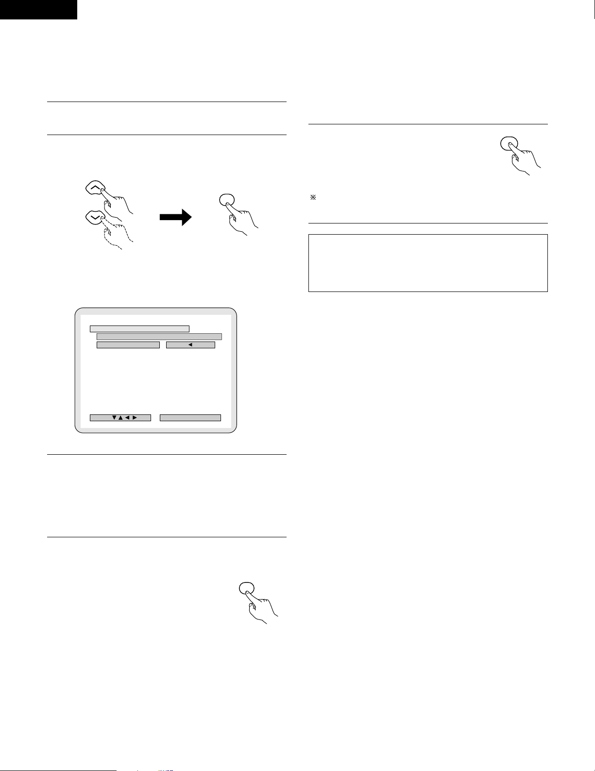
This button can be pressed at any time during the system setup
process to complete the process.
30
ENGLISH
[4] Setting the DVD auto power off
• The ADV-700 is equipped with a function that automatically
switches the power to standby if no operation is performed for 30
minutes while in the stop mode with the function set to DVD. Here,
set whether to turn this function on or off.
• The factory default setting is “NO”.
1
To perform these operations from places other than the
system setting change menu, see page 26.
2
At the “SYSTEM SETUP MENU”.screen, select “DVD AUTO
POWRE OFF”.and press the ENTER button.
• Switch to the “DVD AUTO POWER OFF”.screen.
3
Select “YES” or “NO”.
• YES: The auto power off function is active when the function is set
to DVD.
• NO: The auto power off function does not work.
4
Enter the setting.
• The SYSTEM SETUP MENU reappears.
[5] After completing system setup
• Once the speaker settings, delay time setting and channel level
adjustments are made, there is no need to reset them unless the AV
components or speakers are changed or the speakers are moved to
different positions.
• Change the DVD auto power off settings as necessary.
1
At the SYSTEM SETUP MENU, press
the SETUP button.
• The changed settings are entered and
the on-screen display turns off.
NOTE:
• If the quick system settings are selected after setting up the
system using the system setting change menu, the speaker and
delay time settings are changed to the values preset for the quick
system settings.
B
FINISH: ENTER BUTTON
DVD AUTO POWER OFF
SELECT :
YESYES NONO
(DVD FUNCTION ONLY)(DVD FUNCTION ONLY)
AUTO POWER OFFAUTO POWER OFF
ENTER
SETUP
ENTER
Remote control unit Remote control unit
Remote control unit
Remote control unit
Page 31

31
ENGLISH
1
c 8 1:02:46
D
V
D
T
O
N
E
2
Set discs in the disc tray with the labeled (printed) side facing up.
8 cm disc guide
Disc tray
NOTE:
• Do not move the this unit while a disc is playing. Doing
so may scratch the disc.
(1) Opening and Closing the Disc Tray
q Turn on the power.
w Press the OPEN/CLOSE button.
1
c 8 1:02:46
D
V
D
T
O
N
E
Disc tray
Power button
OPEN/CLOSE button
NOTES:
• Even when the power is in the standby mode, when the
OPEN/CLOSE button is pressed, the ADV-700’s power
turns on and the disc tray operates. (Auto power on
function)
• Even if the function is set to something other than DVD,
when the OPEN/CLOSE button is pressed, the function
switches to DVD and the disc tray operates. (Auto
function select function)
• Do not strike on the button with a pencil, etc.
12 cm disc guide
1
c 8 1:02:46
DVD
TONE
1
(2) Loading Discs
• Pick up the disc carefully so as not to touch the signal surface
and hold it with the labeled side facing up.
• With the disc tray fully open, set the disc in the disc tray.
• Set 12 cm discs in the outer tray guide (Figure 1), 8 cm discs in
the inner tray guide (Figure 2).
• Press the OPEN/CLOSE button. The disc is automatically
loaded.
• The disc tray can also be closed automatically to load the disc
by pressing the PLAY button.
1
c
8
1
:
0
2
:
4
6
D
V
D
T
O
N
E
Figure 1
Outer disc tray
12 cm disc
1
c
8
1
:
0
2
:
4
6
D
V
D
T
O
N
E
Figure 2
Inner disc tray
8 cm disc
NOTES:
• If a foreign object is caught in the disc tray during closing,
simply press the OPEN/CLOSE button again and the tray
will open.
• Do not press the disc tray in by hand when the power is
off. Doing so will damage it.
• Do not place foreign objects in the disc tray. Doing so will
damage it.
TV/VCR
CH
VOL
SLEEP
ON
OFF
2
3
4
56
8
9
CLEAR
CALL
0
+10
7
1
VCR POWERVCR POWER
TV POWERTV POWER
TV
VCR
POWERPOWER
CH
CH
CH
1
(1) Before Operating
(2) Loading Disc
1
Refer to “CONNECTIONS” (pages 8 to 15) and check that all
connections are correct.
2
Turn on the power.
Press the POWER
button.
When pressed, the power turns on and the display lights. The sound
is muted for several seconds, after which the unit operates normally.
When pressed again, the power turns off, the standby mode is set
and the display turns off.
Whenever the ON/STANDBY button is in the STANDBY state, the
apparatus is still connected on AC line voltage. Please be sure to
unplug the cord when you leave home for, say, a vacation.
11
PLAY BACK
ON / STANDBY
ON
POWERPOWER
Light
(green)
Main unit Remote control unit
Page 32

32
ENGLISH
IMPORTANT SETUP INFORMATION
This set has the following presettings: “DISC SETUP”, “OSD SETUP”, “VIDEO SETUP”, “AUDIO SETUP”, “RATINGS”, and “OTHER
SETUP”.
These presettings have been preset upon shipment from the factory. If you wish to change them to suit your specific purposes, refer to pages
71 to 81.
Before operating the remote control unit!
• Be sure to set the DVD mode using the remote
control mode selector buttons.
1
2
3
ON
POWERPOWER
ON / STANDBY
1
c 8 1:02:46
D
V
D
T
O
N
E
Turn on the power.
• Press the power button, the power indicator lights and the
power turns on.
Press the OPEN/CLOSE button to open the disc tray.
Set the disc in the disc tray.
4
OPEN/CLOSE
Press the OPEN/CLOSE button.
5
Press the PLAY button.
• For many interactive DVDs and video CDs with playback
control, a menu screen appears. In this case use the
procedure in step 6 to select the desired item.
✽ Interactive DVDs are DVDs including multiple angles,
stories, etc.
Main unit
Main unit
OPEN/CLOSE
Main unit
Main unit
Remote control unit
Remote control unit
DVD
FUNCTION
/SELECT
MASTER VOLUME
ON / STANDBY
SURROUND
MODE
SDB/TONE
TIMER/SET
STATUS
OPEN/CLOSE
PHONES
DVD SURROUND AMPLIFIER ADV-700
1
c 8 1:02:46
DVD
TONE
(3)-3
(3)-1 (3)-2,(3)-4
(3)-5 (4)-1
(5)-1
VOLUME
ENTER
BAND
MODE
MENU
FUNCTION
DISPLAY RETURN INPUT MODE SURROUND
MUTE
SHIFT
CH
TU
TV/VCR
CH
VOL
SLEEP
ON
OFF
2
3
4
56
8
9
CLEAR
CALL
0
+10
7
1
STATUS
VCR POWERVCR POWER
TV POWERTV POWER
TV
VCR
NTSC/PAL
MEMO
POWERPOWER
CH
CH
CH
(3)-
7
(5)-
1
(3)-
6
(3)-1
(3)-5
(4)-1
(3)-6
Example: For DVDs with menu
screens
Example: For video CDs with
playback control
1. Opening
Banana
Strawberry
Pineapple
TOP MENU
Orange
Peach
Apple
2. 1st movement
3. 2nd movement
4. 3rd movement
5. Ending
(3) Playback
Light
(green)
Page 33

33
ENGLISH
67
Use the cursor buttons ( , , and ) to select the
desired item.
• For some discs there is a second menu screen. If so, press
the 9 button to display the next menu screen. (See the
disc’s jacket.)
✽ The cursor buttons ( , , and ) do not work for
video CDs. Use the number buttons to select the desired
item.
Press the ENTER button.
• The desired item is selected and playback starts.
• You can return to the menu screen by pressing the TOP
MENU button while the DVD is playing, though this
depends on the disc.
• Press the RETURN button during playback of a video CD to
return to the menu screen.
Remote control unit
Remote control unit
Example: When “Apple” is
selected
Apple
ENTER
Banana
Strawberry
Pineapple
TOP MENU
Orange
Peach
Apple
• If appears on the TV screen while buttons are being
operated, that operation is not possible on the ADV-700 or
with that disc.
• Set the disc in the disc guide.
• Only set one disc in the tray.
• The disc keeps turning while the menu screen is displayed on
the TV screen.
NOTES
:
✽ The resume play memory function only works for
discs for which the elapsed time is shown on the
display during playback.
1
1
During playback, press the STOP button on the main unit or
the remote control unit, playback stops and wall paper is
displayed.
<Resume play memory function (DVD only)>
• With the
ADV-700
, when the STOP button is pressed, that
position is stored in the memory. At this time, “1” flashes
on the display. When the PLAY button is pressed after
pressing the STOP button, playback resumes from the
position at which it was stopped.The resume play memory
function is canceled if the disc tray is opened or the STOP
button is pressed a second time.
Auto power off function.
• The ADV-700 is equipped with a function that automatically
switches the power to standby if no operation is performed
for 30 minutes while in the stop mode with the function set
to DVD.
• This function is set to off upon shipment from the factory.
If you wish to turn it on, set the “DVD auto power off
setting” to “YES” as described on page 30.
During playback, press the PAUSE button on the main unit or
the remote control unit.
• Press the PLAY button to resume normal playback.
Main unit
Remote control unit
Main unit
Remote control unit
(4) Stopping Playback
(5) Playing Still Pictures (Pausing)
Page 34

34
ENGLISH
NOTE:
• In some cases the menu screen may reappear when
one of the 6 / 7 buttons is pressed during menu
playback on a video CD.
1
During playback, press one of the 6 / 7 buttons on the
remote control unit.
6 : Reverse direction
7 : Forward direction
• When pressed again, the search speed increases (in four
steps).
• Press the PLAY button to resume normal playback.
Remote control unit
FUNCTION
/SELECT
MASTER VOLUME
ON / STANDBY
SURROUND
MODE
SDB/TONE
TIMER/SET
STATUS
OPEN/CLOSE
PHONES
DVD SURROUND AMPLIFIER ADV-700
1
c 8 1:02:46
DVD
TONE
(8)-1 (7)-1
VOLUME
ENTER
BAND
MODE
MENU
FUNCTION
TOP MENU
SETUP
SDB/TONE
MUTE
SURR.PARA
SUB TITLE ANGLE
AUDIO
SHIFT
CH.SELECT
CH
T.TONE
TU
PROG/DIRECT
REPEAT A-B
REPEAT RANDOM
DVD
REMOCON MODE
STATUS
CDR/MD/TAPE
TUNER/TV/VCR
VCR POWER
TV POWER
NTSC/PAL
MEMO
POWER
(8)-1
(7)-1
(6)-1,(9)-1
1
During playback, press one of the skip buttons on the main
unit or the remote control unit.
8 / : Reverse direction (PREVIOUS)
9 / : Forward direction (NEXT)
• A number of chapters or tracks equal to the number of
times the button is pressed is skipped.
• When the skip back button is pressed once, the pickup
returns to the beginning of the currently playing chapter or
track.
(6) Forward / Reverse Searching
(7) Skipping to the Beginning of Chapters or Tracks
Playing position
Chapter/Track Chapter/Track Chapter/Track Chapter/Track
Reverse direction ,/Forward direction (direction of playback)
CH
NOTE:
• In some cases the menu screen may reappear when
one of the 8 / 9 buttons is pressed during
menu playback on a video CD.
Main unit Remote control unit
1
During playback, press the 3 button on the main unit or the
remote control unit.
• The picture moves forward one frame each time the button
is pressed.
• Press the PLAY button to resume normal playback.
(8) Playing Frame by Frame (for DVDs and video CDs only)
Main unit Remote control unit
1
In the still mode, press one of the 6 / 7 buttons on the
remote control unit.
6 : Reverse direction
7 : Forward direction
• When pressed again, the slow play speed increases.
(Four step) (Three step on video CDs)
• Press the PLAY button to resume normal playback.
(9) Slow Playback (for DVDs and video CDs only)
Remote control unit
NOTE:
• Reverse slow play is not possible on video CDs.
Before operating the remote control unit!
• Be sure to set the DVD mode using the remote
control mode selector buttons.
DVD
Page 35

35
1
c 8 1:02:46
DVD
TONE
1,3 5
3
VOLUME
ENTER
BAND
MODE
MENU
FUNCTION
DISPLAY RETURN INPUT MODE SURROUND
MUTE
SHIFT
CH
TV/VCR
CH
VOL
SLEEP
OFF
4
56
8
9
CLEAR
CALL
0
+10
7
STATUS
VCR POWERVCR POWER
TV POWERTV POWER
TV
VCR
NTSC/PAL
POWERPOWER
CH
CH
1
3
5
2
12
OPERATION
Playing the input source
1
Either turn the FUNCTION/SELECT dial on the main unit or
press the FUNCTION button on the remote control unit to
select the input source you want to play.
The presence or absence of digital signals is detected, the
signals input to the digital input are identified and decoding
and playback are performed automatically in DTS, Dolby
Digital or PCM (2 channel stereo) format. If no digital signal
(TV DRS and V.AUX) is being input, the analog input jacks
are selected.
Use this mode to play Dolby Digital signals.
w PCM (exclusive PCM signal playback mode)
Decoding and playback are only performed when PCM
signals are being input.
Note that noise may be generated when using this mode
to play signals other than PCM signals.
e DTS (exclusive DTS signal playback mode)
Decoding and playback are only performed when DTS
signals are being input.
r ANALOG (exclusive analog audio signal playback mode)
The signals input to the analog input jacks are decoded and
played.
(This cannot be selected in the DVD mode.)
FUNCTION
/SELECT
FUNCTION
• The function switches as shown below.
• The function only changes in the “Æ” direction when
operated from the remote control unit.
• The function switches as shown below.
• The function only changes in the “Æ” direction when
operated from the remote control unit.
TUNER DVD
CDR/TAPE VCR
TV/DBS
V.AUX
2
If “DVD”, “TV/DBS” or “V.AUX” is selected as the input
source, press the INPUT MODE button on the remote
control unit to select the input mode.
Input mode selection function
This can be selected for the “DVD”, “TV/DBS” and
“V.AUX” input sources.
Different input modes can be selected for the different
input sources. The selected input modes for the separate
input sources are stored in the memory.
q AUTO (auto mode)
In this mode, the types of signals being input to the digital
and analog input jacks for the selected input source are
detected and the program in the ADV-700’s surround
decoder is selected automatically upon playback.
INPUT MODE
•“ANALOG” cannot be selected when “DVD” is selected as
the input source.
AUTO PCM DTS ANALOG
Main unit Remote control unit
Remote control unit
3
Either press the SURROUND MODE button on the main unit
then turn the FUNCTION/SELECT dial or press the
SURROUND button on the remote control unit to select the
play mode.
SURROUND
MODE
STEREO
STEREO
AUTO DECODE 5CH STEREO MONO MOVIE
ROCK ARENA
DIRECT
JAZZ CLUB
VIRTUAL
VIDEO GAME
MATRIX
...
Main unit
FUNCTION
/SELECT
Main unit
SURROUND
Remote control unit
NOTE:
• The input mode is automatically set to “AUTO” when the input
is switched to DVD.
ENGLISH
Page 36

36
4
Start playback on the selected component.
• For operating instructions, refer to the component’s
manual.
• The volume can be adjusted within the range of –60 to 0 to
18 dB. However, when the channel level is set as
described, if the volume for any channel is set at +1 dB or
greater, the volume cannot be adjusted up to 18 dB. (In this
case the maximum volume adjustment range is “18 dB —
(Maximum value of channel level)”.)
5
Either turn the MASTER VOLUME dial on the main unit or
use the VOLUME buttons on the remote control unit to
adjust the volume.
M.VOLUME -20
Main unit
VOLUME
Remote control unit
The volume level is displayed
on the display.
NOTE:
• The digital input indicator will light when “DIG” playing CDROMs containing data other than audio signals, but no sound
will be heard.
Input mode when playing DTS sources
• Noise will be output if DTS-compatible CDs or LDs are played in
the “ANALOG” or “PCM” mode.
When playing DTS-compatible sources, be sure to connect the
source component to the digital input jacks (OPTICAL/COAXIAL)
and set the input mode to “DTS”.
• Noise may be generated at the beginning of playback and while
searching during DTS playback in the AUTO mode. If so, play in
the DTS mode.
• The “DIG” lights when digital signals are being input properly. If the
LED does not light, check whether the digital input component
setup and connections are correct and whether the component’s
power is turned on.
PRO LOGIC II
DIG
PCM
DIGITAL
DTS
DIG
PCM
DIGITAL
DTS
DIG
PCM
DIGITAL
DTS
AUTO
ANA
DIG
PCM DTS
ANA
DIG
PCM
AUTO
DTS
ANA
DIG
PCM
AUTO
DTS
ANA
DIG
PCM
AUTO
DTS
Input mode display
• In the AUTO mode
• In the DIGITAL PCM mode
• In the DIGITAL DTS mode
• In the ANALOG mode
One of these lights, depending on
the input signal.
Lit
One of these
lights,
depending on
the input signal.
Input signal display
• DOLBY DIGITAL
• DTS
• PCM
STATUS
Main unit
FUNCTION
/SELECT
Main unit
STATUS
Remote control unit
2 Cheking the currently playing program source, etc.
Either press the STATUS button on the main unit then turn
the FUNCTION / SELECT dial or press the STATUS button
on the remote control unit to check the unit’s operating
status.
ENGLISH
MASTER VOLUME
Page 37

37
1
c 8 1:02:46
DVD
TONE
12
1
c 8 1:02:46
DVD
TONE
1
VOLUME
ENTER
BAND
MODE
TOP MENU
SETUP
SDB/TONE
MUTE
SURR.PARA
SUB TITLE ANGLE
AUDIO
SHIFT
CH.SELECT
CH
T.TONE
TU
PROG/DIRECT
REPEAT A-B
REPEAT RANDOM
DVD
REMOCON MODE
STATUS
CDR/MD/TAPE
TUNER/TV/VCR
VCR POWER
TV POWER
NTSC/PAL
MEMO
POWER
1
2
2
VOLUME
BAND
MODE
TOP MENU
SETUP
SDB/TONE
MUTE
SURR.PARA
SUB TITLE ANGLE
AUDIO
SHIFT
CH.SELECT
CH
T.TONE
TU
PROG/DIRECT
REPEAT A-B
REPEAT RANDOM
DVD
REMOCON MODE
STATUS
CDR/MD/TAPE
TUNER/TV/VCR
VCR POWER
TV POWER
NTSC/PAL
MEMO
POWER
1
After starting playback
[1] Adjusting the sound quality (SDB / TONE)
The SDB/TONE function will not work in the direct mode.
[2] Turning the sound off temporarily (MUTING)
[3] Listening over head phones
1
Press the SDB/TONE button.
• The tone switches as follows each time the SDB/TONE
button is pressed.
DEFEAT
• The signals do not pass through the SDB, bass and treble
adjustment circuits, providing higher quality sound.
SDB
• Either turn the FUNCTION / SELECT dial or use the ( ,
) cursor buttons to select “ON” or “OFF”.
BASS, TREBLE
• To increase the bass or treble: Turn the control clockwise or
press the cursor button. (The bass or treble sound can be
increased to up to +10 dB in steps of 2 dB.)
• To decrease the bass or treble: Turn the control clockwise
or press the cursor button. (The bass or treble sound can be
decreased to up to –10 dB in steps of 2 dB.)
✽ If no operation is performed within 4 seconds, the display
switches back to what was previously displayed.
SDB/TONE
SDB/TONE
1
Use this to turn off the audio output temporarily.
Press the MUTE button.
✽Cancelling MUTE mode.
Press the MUTE button again.
MUTE
DEFEAT SDB
(ON/OFF)
BASS TREBLE
Main unit Remote control unit
Remote control unit
2
With the name of the volume to be adjusted selected, turn
the FUNCTION/SELECT knob or cursor button ( , ) to
adjust the level.
FUNCTION
/SELECT
Main unit Remote control unit
NOTE:
• The setting is canceled if the set’s power is turned off.
1
Connect the headphones to the PHONES jack of the front
panel.
✽The output to the speaker automatically is turned off and
no sound is produced from the speakers.
PHONES
ENGLISH
Page 38

38
ENGLISH
Surround
This unit is equipped with a digital signal processing circuit that lets you play program sources in the surround mode to achieve the same sense
of presence as in a movie theater.
Dolby Surround
(1) Dolby Digital (Dolby Surround AC-3)
Dolby Digital is the multi-channel digital signal format developed by Dolby Laboratories.
Dolby Digital consists of up to “5.1” channels - front left, front right, center, surround left, surround right, and an additional channel exclusively
reserved for additional deep bass sound effects (the Low Frequency Effects – LFE – channel, also called the “.1” channel, containing bass
frequencies of up to 120 Hz).
Unlike the analog Dolby Pro Logic format, Dolby Digital’s main channels can all contain full range sound information, from the lowest bass, up
to the highest frequencies – 22 kHz. The signals within each channel are distinct from the others, allowing pinpoint sound imaging, and Dolby
Digital offers tremendous dynamic range from the most powerful sound effects to the quietest, softest sounds, free from noise and distortion.
2 Dolby Digital and Dolby Pro Logic
Comparison of home surround systems
No. recorded channels (elements)
No. playback channels
Playback channels (max.)
Audio processing
High frequency playback limit of surround
channel
Dolby Digital
5.1 ch
5.1 ch
L, R, C, SL, SR, SW
Digital discrete processing Dolby Digital (AC-3) encoding/decoding
20 kHz
Dolby Pro Logic
2 ch
4 ch
L, R, C, S (SW - recommended)
Analog matrix processing Dolby Surround
7 kHz
2 Dolby Digital compatible media and playback methods
Marks indicating Dolby Digital compatibility: and .
The following are general examples. Also refer to the player’s operating instructions.
Media
LD (VDP)
DVD
Others
(satellite broadcasts, CATV, etc.)
Dolby Digital output jacks
Coaxial Dolby Digital RF output jack
1
Optical or coaxial digital output
(same as for PCM)
2
Optical or coaxial digital output
(same as for PCM)
Playback method (reference page)
Set the input mode to “AUTO”.
(Page 35, 36)
Set the input mode to “AUTO”.
(Page 35, 36)
Set the input mode to “AUTO”.
(Page 35, 36)
1 Use a commercially available adapter to connect Dolby Digital RF (AC-3RF) output signals to the digital input terminals. (Refer to the
adapter’s operating instructions.)
Please refer to the instruction manual of the adapter when making connection.
2 To play in Dolby Digital Surround on the ADV-700, set “DVD setting change” – “Audio setting” – “Digital output” to “Normal” in the setup.
(The factory default is “Normal”.)
(2) Dolby Pro Logic II
• Dolby Pro Logic II is a new multi-channel playback format developed by Dolby Laboratories using feedback logic steering technology and
offering improvements over conventional Dolby Pro Logic circuits.
• Dolby Pro Logic II can be used to decode not only sources recorded in Dolby Surround ( ) but also regular stereo sources into five channels
(front left, front right, center, surround left and surround right) to achieve surround sound.
• Whereas with conventional Dolby Pro Logic the surround channel playback frequency band was limited, Dolby Pro Logic II offers a wider
band range (20 Hz to 20 kHz or greater). In addition, the surround channels were monaural (the surround left and right channels were the
same) with previous Dolby Pro Logic, but Dolby Pro Logic II they are played as stereo signals.
•
Various parameters can be set according to the type of source and the contents, so it is possible to achieve optimum decoding (see page 42).
Sources recorded in Dolby Surround
These are sources in which three or more channels of surround have been recorded as two channels of signals using Dolby Surround
encoding technology.
Dolby Surround is used for the sound tracks of movies recorded on DVDs, LDs and video cassettes to be played on stereo VCRs, as well
as for the stereo broadcast signals of FM radio, TV, satellite broadcasts and cable TV.
Decoding these signals with Dolby Pro Logic makes it possible to achieve multi-channel surround playback. The signals can also be played
on ordinary stereo equipment, in which case they provide normal stereo sound.
There are two types of DVD Dolby surround recording signals.
q 2-channel PCM stereo signals
w 2-channel Dolby Digital signals
Regardless of the signal being played, when the 2-channel decode mode is set to the “Pro Logic II” mode in the “AUTO DECODE” mode,
the surround mode is automatically set to “Dolby Pro Logic II”.
13
DOLBY / DTS SURROUND
Page 39

39
ENGLISH
2 Sources recorded in Dolby Surround are indicated with the logo mark shown below.
Dolby Surround support mark:
Manufactured under license from Dolby Laboratories.
“Dolby”, “Pro Logic” and the double-D symbol are trademarks of Dolby Laboratories.
Confidential Unpublished Works, ©1992-1999 Dolby Laboratories. All rights reserved.
DTS Digital Surround
Digital Theater Surround (also called simply DTS) is a multi-channel digital signal format developed by Digital Theater Systems.
DTS offers the same “5.1” playback channels as Dolby Digital (front left, front right and center, surround left and surround right) as well as the
stereo 2-channel mode. The signals for the different channels are fully independent, eliminating the risk of deterioration of sound quality due to
interference between signals, crosstalk, etc.
DTS features a relatively higher bit rate as compared to Dolby Digital (1234 kbps for CDs and LDs, 1536 kbps for DVDs) so it operates with a
relatively low compression rate. Because of this the amount of data is great, and when DTS playback is used in movie theaters, a separate CDROM synchronized with the film is played.
With LDs and DVDs, there is of course no need for an extra disc; the pictures and sound can be recorded simultaneously on the same disc, so
the discs can be handled in the same way as discs with other formats.
Other media include CDs recorded in DTS. These are the same discs as conventional CDs (recorded in 2 channels) but include 5.1 channel
surround signals. They do not include images, but they do permit surround playback on the ADV-700 and on CD players.DTS surround track
playback offers the same intricate, grand sound as in a movie theater, right in your own listening room.
2 DTS compatible media and playback methods
Marks indicating DTS compatibility: and .
The following are general examples. Also refer to the player’s operating instructions.
Media
CD
LD (VDP)
DVD
DTS Digital output jacks
Optical or coaxial digital output
(same as for PCM) 2
Optical or coaxial digital output
(same as for PCM) 2
Optical or coaxial digital output
(same as for PCM) 3
Playback method (reference page)
Set the input mode to “AUTO” or “DTS” (page 35, 36).
Never set the mode to “ANALOG” or “PCM”. 1
Set the input mode to “AUTO” or “DTS” (page 35, 36).
Never set the mode to “ANALOG” or “PCM”. 1
Set the input mode to “AUTO” or “DTS” (page 35, 36).
1 DTS signals are recorded in the same way on CDs and LDs as PCM signals. Because of this, the un-decoded DTS signals are output as
random “hissy” noise from the CD or LD player’s analog outputs. If this noise is played with the amplifier set at a very high volume, it
may possibly cause damage to the speakers. To avoid this, be sure to switch the input mode to “AUTO” or “DTS” before playing CDs or
LDs recorded in DTS. Also, never switch the input mode to “ANALOG” or “PCM” during playback. The same is true when playing CDs
and LDs recorded in DTS on the ADV-700 or on LD/DVD compatible players. With DVDs, the DTS signals are recorded with a special
recording method so there is no problem. For DVDs, the DTS signals are recorded in a special way so this problem does not occur.
2 The signals provided at the digital outputs of a CD or LD player may undergo some sort of internal signal processing (output level
adjustment, sampling frequency conversion, etc.). In this case the DTS-encoded signals may be processed erroneously, in which case they
cannot be decoded by this unit, or may only produce noise. Before playing DTS signals for the first time, turn down the master volume to
a low level, start playing the DTS disc, then check whether the DTS indicator on this unit (see page 36) lights before turning up the master
volume.
3 To play in DTS Digital Surround on the ADV-700, set “DVD setting change” — “Audio setting” — “Digital output” to “Normal” in the
setup. (The factory default is “Normal”.)
“DTS” and “DTS Digital Surround” are registered trademarks of Digital Theater Systems, Inc.
Page 40

40
ENGLISH
(1)
Before playing with the surround function
• Adjustments using the test tones can only be performed in the
“Auto” mode and are only valid for the Auto decode Surround
modes. The adjusted levels are automatically stored in the memory.
• Even after adjusting using the test tones, the various channels can
be adjusted using the procedure described below to suit the
program source and your preferences.
VOLUME
ENTER
BAND
MODE
MENU
FUNCTION
DISPLAY RETURN INPUT MODE SURROUND
TOP MENU
SETUP
SDB/TONE
MUTE
SURR.PARA
SUB TITLE ANGLE
AUDIO
SHIFT
CH.SELECT
CH
T.TONE
TU
PROG/DIRECT
REPEAT A-B
REPEAT RANDOM
DVD
TV/VCR
SLEEP
REMOCON MODE
8
9
CLEAR
CALL
0
+10
7
STATUS
CDR/MD/TAPE
TUNER/TV/VCR
VCR POWER
TV POWERTV POWER
TV
NTSC/PAL
MEMO
POWER
CH
2
1,3
2
VOLUME
ENTER
BAND
MODE
MENU
FUNCTION
DISPLAY RETURN INPUT MODE SURROUND
TOP MENU
SETUP
SDB/TONE
MUTE
SURR.PARA
SUB TITLE ANGLE
AUDIO
SHIFT
CH.SELECT
CH
T.TONE
TU
PROG/DIRECT
REPEAT A-B
REPEAT RANDOM
DVD
TV/VCR
SLEEP
REMOCON MODE
8
9
CLEAR
CALL
0
+10
7
STATUS
CDR/MD/TAPE
TUNER/TV/VCR
VCR POWER
TV POWERTV POWER
TV
NTSC/PAL
MEMO
POWER
CH
2
1
2
1
Press the TEST TONE button.
T.TONE
Remote control unit
3
After adjusting using the test tones, adjust the channel levels
either according to the playback sources or to suit your tastes,
as described below.
T.TONE
Remote control unit
2
Test tones are output from the different speakers. Use the
channel volume adjust buttons to adjust so that the volume of
the test tones is the same for all the speakers.
• The channel to be adjusted can be changed using the
CH.SELECT button and the ( and ) cursor buttons on
the remote control unit during the adjustments using the
test tones.
Remote control unit
1
Select the speaker whose level you want to adjust.
• The channel switches as shown below each time the
button is pressed.
CH.SELECT
Remote control unit
Remote control unit
2
Adjust the volume level of the selected speaker while the
channel level is displayed.
14
SURROUND PLAYBACK
Page 41

41
ENGLISH
(2)
Auto decode surround mode settings
• The auto decode surround mode can be used for multi-channel and 2-channel stereo playback in the Dolby Digital, Dolby Pro Logic II, and DTS
surround modes, according to the input signal’s format.
• Here we describe the 2-channel decode mode settings for setting whether to play 2-channel sources as such in the 2-channel mode or in the
multi-channel mode, as well as the settings for the Dolby Pro Logic II mode.
[1] 2-channel decode mode settings
• In the auto decode surround mode for the DVD, TV/DBS and V.AUX functions, you can select and set the auto stereo mode for playing 2-channel
sources in 2-channel stereo, or the Pro Logic II mode for using Dolby Pro Logic II processing to achieve multi-channel playback.
1
c 8 1:02:46
DVD
TONE
1 1
VOLUME
ENTER
BAND
MODE
MENU
FUNCTION
DISPLAY RETURN INPUT MODE SURROUND
TOP MENU
SETUP
SDB/TONE
MUTE
SURR.PARA
SUB TITLE ANGLE
AUDIO
SHIFT
CH.SELECT
CH
T.TONE
TU
PROG/DIRECT
REPEAT A-B
REPEAT RANDOM
DVD
CALL
0
+10
STATUS
CDR/MD/TAPE
TUNER/TV/VCR
VCR POWER
TV POWER
NTSC/PAL
MEMO
POWER
2
3
1
3
1
With the function set to DVD, TV/DBS or V.AUX, select the
auto decode surround mode.
•“AUTO decode” is displayed, then the normal display
reappears.
SURROUND
MODE
Main unit
FUNCTION
/SELECT
Main unit
SURROUND
Remote control unit
2
Press the SURR.PARA button on the remote control unit and
select the 2-channel decode mode.
SURR.PARA
Remote control unit
2ch DEC A-ST
✽ This can be selected when the digital input consists of no
signal, PCM signals, Dolby Digital 2-channel signals, as well
as when the analog input is selected.
3
Select the desired 2-channel decode mode using the ( and
) cursor buttons on the remote control unit.
• The mode switches as follows each time one of the
buttons is pressed:
Remote control unit
✽ When making parameter settings, the display will return to
the regular condition several seconds after the last button
was pressed and the setting will be completed.
A-ST PLII
(auto stereo mode) (Pro Logic II mode)
Surround parameters (1)
(2-channel decode mode)
A-ST (auto stereo) mode
• 2-channel sources are played in 2-channel stereo.
When this mode is selected in the auto decode surround
mode, DVD, BS digital and other multi-channel sources are
played as such with multiple channels, while CDs and other
2-channel sources are automatically played in stereo.
✽ For 2-channel Dolby Digital sources decoded in Dolby
Surround, identification signals are used to automatically
process the signals in Dolby Pro Logic II and play them in the
multi-channel mode.
PLII (Pro Logic II) mode
• Even 2-channel sources undergo Dolby Pro Logic II
processing and are played in the multi-channel mode.
When this mode is selected in the auto decode surround
mode, DVD, BS digital and other multi-channel sources are
played as such with multiple channels, and CDs and other 2channel sources also automatically undergo Dolby Pro Logic
II processing and are played in the multi-channel mode.
✽ In the Dolby Pro Logic II mode, “CINEMA”, “MUSIC” or
“DOLBY PL” (Pro Logic) can be selected and set. (See page
42 for setting instructions.)
NOTE:
• The 2-channel decode mode cannot be set when Dolby Digital
5.1-channel signals or DTS signals are being input.
• The 2-channel decode mode is stored separately for the DVD,
TV/DBS and V.AUX modes. (In the Dolby Pro Logic II mode, the
“CINEMA”, “MUSIC” or “DOLBY PL” (Pro Logic) mode is also
stored in the memory.)
Page 42

42
ENGLISH
[2] Dolby Pro Logic II mode settings
• Use the Dolby Pro Logic II mode to play program sources with the mark and CDs and other 2-channel sources
with Dolby Pro Logic II processing.
• One of the following three modes can be selected in the Dolby Pro Logic II mode:
q CINEMA mode: This mode is optimum for movies and other Dolby Surround programs.
w MUSIC mode: This mode is optimum for stereo music programs.
e PRO LOGIC compatible mode: This is the conventional Dolby Surround Pro Logic mode.
1
c 8 1:02:46
DVD
TONE
1
1
VOLUME
ENTER
BAND
MODE
MENU
FUNCTION
DISPLAY RETURN INPUT MODE SURROUND
TOP MENU
SETUP
SDB/TONE
MUTE
SURR.PARA
SUB TITLE ANGLE
AUDIO
SHIFT
CH.SELECT
CH
T.TONE
TU
PROG/DIRECT
REPEAT A-B
REPEAT RANDOM
DVD
TV/VCR
CH
VOL
SLEEP
ON
OFF
REMOCON MODE
2
3
4
56
8
9
CLEAR
CALL
0
+10
7
1
STATUS
CDR/MD/TAPE
TUNER/TV/VCR
VCR POWERVCR POWER
TV POWERTV POWER
TV
VCR
NTSC/PAL
MEMO
POWERPOWER
CH
CH
CH
2,4
3,5
1
3,5
1
Set the surround mode to “AUTO DECODE”.
SURROUND
MODE
Main unit
FUNCTION
/SELECT
Main unit
SURROUND
Remote control unit
✽ This can be selected when the digital input consists of no
signal, PCM signals, Dolby Digital signals, as well as when
the analog input is selected.
(It cannot be set when Dolby Digital or DTS signals are
being input.)
2
Press the SURR.PARA button on the remote control unit to
display the Dolby Pro Logic II mode setting.
SURR.PARA
Remote control unit
PLII CINEMA
3
Select the optimum mode according the source.
Remote control unit
PLII DOLBY PL PLII CINEMA PLII MUSIC
4
Set the surround parameters
according to the selected mode.
• The parameters switch as shown
below each time the button is
pressed.
DEFAULT
DEFAULT PANORAMA
DIMENSION
CENTER WIDTH
DEFAULT
PL
II CINEMA PLII MUSICPLII DOLBY PL
SURR.PARA
Remote control unit
,/
Page 43

43
ENGLISH
5
Set the various surround parameters.
• PANORAMA setting
PANORA ON
OFF
ON OFF
• DIMENSION setting
DIMENSION 3
0 3
,/
6
,/
... ...
• CENTER WIDTH setting
CENTER WIDTH 0
0 4 7
,/
... ...
• DEFAULT setting
DEFAULT Y
N
YES
YN
NO
,/
• If “YES” is selected, the settings are reset to the factory
defaults.
✽ Stop operating buttons once the surround parameter
settings have been completed. After several seconds the
normal display reappears and the settings are automatically
set.
✽ This completes the Dolby Pro Logic II mode settings.
Other parameters can also be input, depending on the input
signal. Refer to page 51 for details.
NOTES:
• The Dolby Pro Logic II mode is stored in the memory individually
for the different functions.
• Dolby Pro Logic II includes four Pro Logic modes: “NORMAL”,
“PHANTOM”, “WIDE” and “3CH.LOGIC”. These are set
automatically by making the “Speaker settings (setting of
speaker type and whether or not that channel is connected)” in
the setup.
• It is not possible to play DTS digital input sources in the Dolby
Pro Logic II mode.
Surround parameters (2)
(Dolby Pro Logic II mode)
CINEMA mode
• This mode is suited for playing movies recorded in Dolby
Surround as well as regular sources recorded in stereo. A
high precision decoder decodes the signals into 5 channels,
resulting in uniform 360 degree surround sound even with
2-channel sources.
The MUSIC mode may be more effective for sources
containing a high ratio of stereo music. Try both and choose
the most effective mode.
MUSIC mode
• This mode is suited for surround playback of stereo music
signals. The inverted phase signals (the reverberation
component of the music signals contains a high ratio of
these) are played from the surround channel, and at the
same time the frequency response of the surround channel
is optimized to achieve a natural sound with a sense of
expansion.
With music signals, the sound field expansion differs greatly
according to the type of music, the recording conditions
(live, etc.) and the contents of the signal source. Because of
this, the MUSIC mode includes optional parameters for
further adjusting the sound field.
PANORAMA
The front stereo sound field image is extended to the
surround channel.
This is effective if under normal conditions the stereo image
is narrow and the surround effect seems weak.
DIMENSION
This shifts the center of the sound field image to the front
or surround side.
The playback balance of the different channels can be
adjusted regardless of the amount of reverberation
component in the source. If the sound field image is biased
towards the front or surround side, this optional parameter
can be used to correct it.
CENTER WIDTH
This adjusts the method of playback of the center signal
component from the center channel only to the front
channel only.
When the center channel is played in a way prioritizing
separation, the position of the front channel sound field is
clearer but the overall sound field image concentrates at the
center and the relationship between the different channels
seems weaker. This parameter can be adjusted to improve
the sense of stability of the sound field image and achieve
natural horizontal expansion.
DOLBY PL (Pro Logic) mode
• This is the conventional Dolby Pro Logic compatible mode.
In this mode sources recorded in Dolby Surround are
decoded with a playback image faithful to the original
recording.
✽ The selected setting (“ON” or “OFF”) flashes.
Page 44

44
ENGLISH
(3) AUTO DECODE mode
• In the auto decode mode, it is possible to play signals in the Dolby Digital, Dolby Pro Logic II or DTS, according to the format of the input signals.
• It is also possible to play 2-channel sources according to the 2-channel decode mode and Dolby Pro Logic II mode settings (pages 42 and 43)
and in the Dolby Pro Logic II Surround mode.
[1] Dolby Digital and DTS playback (digital inputs only)
• Applicable sources
• Digital inputs (TV/DBS and V.AUX functions, including DVD
playback discs)
Dolby Digital multi-channel sources
DTS sources
1
c 8 1:02:46
DVD
TONE
1,3
3
VOLUME
ENTER
BAND
MODE
MENU
FUNCTION
DISPLAY RETURN INPUT MODE SURROUND
TOP MENU
SETUP
SDB/TONE
MUTE
SURR.PARA
SUB TITLE ANGLE
AUDIO
SHIFT
CH.SELECT
CH
T.TONE
TU
PROG/DIRECT
REPEAT A-B
REPEAT RANDOM
DVD
TV/VCR
CH
VOL
SLEEP
ON
OFF
REMOCON MODE
2
3
4
56
8
9
CLEAR
CALL
0
+10
7
1
STATUS
CDR/MD/TAPE
TUNER/TV/VCR
VCR POWERVCR POWER
TV POWERTV POWER
TV
VCR
NTSC/PAL
MEMO
POWERPOWER
CH
CH
CH
5
6
3
1
6
2
1
Select the digital input function. (DVD or TV/DBS or V.AUX
digital input)
FUNCTION
/SELECT
Main unit
FUNCTION
Remote control unit
2
Set the input mode to “AUTO”.
✽ DTS sources can also be played in
the input mode “DTS”.
INPUT MODE
Remote control unit
3
Set the surround mode to “AUTO DECODE”.
SURROUND
MODE
Main unit
FUNCTION
/SELECT
Main unit
SURROUND
Remote control unit
✽ When performing this operation from the main unit, press
the SURROUND MODE button then turn the
FUNCTION/SELECT dial to choose the surround mode.
4
Play a program source containing the or
mark.
• The Dolby Digital indicator lights
when playing a Dolby Digital
source.
• The DTS indicator lights when
playing a DTS source.
DIGITAL
Lit
DTS
Lit
✽ The mode is selected automatically according to the
format of the source being played.
5
Display the surround parameters for
the source.
✽ The surround parameters are also
displayed on the screen when the
function is set to DVD.
SURR.PARA
Remote control unit
6
Select the various surround parameters and set them.
✽ The display returns to normal if no operation is performed
for 4 seconds while the parameters are displayed.
Remote control unit
• D.COMP. setting
D.COMP. OFF
OFF LOW MID HI
,/
✽ This parameter is not displayed when playing DTS source.
Page 45

45
ENGLISH
• LFE level setting
LFE 0dB
,/
✽ The LFE level can be adjusted between –10 dB and 0 dB in
steps of 1 dB.
-10 -5 0
... ...
• DEFAULT setting
DEFAULT Y
N
YES NO
,/
✽ When “YES” is selected, the settings are reset to their
factory default values.
✽ Stop operating buttons once the surround parameter
settings have been completed. After several seconds the
normal display reappears and the settings are automatically
set.
6
NOTES:
• When “DEFAULT” is selected and the cursor button is
pressed (“YES”), “D.COMP.” is automatically set to “OFF” and
“LFE” is reset to the default value.
(“D.COMP.” is not valid for DTS source.)
• Signals encoded in Dolby Digital can only be played in the Auto
decode (Dolby Digital, Dolby Pro Logic II or Auto stereo), Direct,
stereo or virtual modes. Other modes do not work when playing
Dolby Digital signals.
• DTS signals can only be played in the Auto decode (DTS), Direct
or stereo modes. Other modes do not work when playing DTS
signals.
• DTS signals can also be played in the “DTS” input mode. (See
page 35.) In this case, decoding and playback are only
performed when DTS signals are input.
Surround parameters (3)
D.COMP. (Dynamic Range Compression):
• Motion picture soundtracks have tremendous dynamic
range (the contrast between very soft and very loud
sounds). For listening late at night, or whenever the
maximum sound level is lower than usual, the Dynamic
Range Compression allows you to hear all of the sounds in
the soundtrack (but with reduced dynamic range). (This only
works when playing program sources recorded in Dolby
Digital.) Select one of the four parameters (“OFF”, “LOW”,
“MID” (middle) or “HI” (high)). Set to OFF for normal
listening.
LFE (Low Frequency Effect):
• Program source and adjustment range
1. Dolby Digital: –10 dB to 0 dB
2. DTS Surround: –10 dB to 0 dB
• When Dolby Digital encoded software is played, it is
recommended that the LFE LEVEL be set to 0 dB for correct
Dolby Digital playback.
• When DTS encoded movie software is played, it is
recommended that the LFE LEVEL be set to 0 dB for correct
DTS playback.
• When DTS encoded music software is played, it is
recommended that the LFE LEVEL be set to –10 dB for
correct DTS playback.
Page 46

46
ENGLISH
[2] Dolby Surround Pro Logic II mode
....................................................................................................................................................................
(All function)
• The source is played according to the 2-channel decode mode and Dolby Pro Logic II mode settings.
• Applicable sources
• Digital inputs (TV/DBS and V.AUX functions, including DVD
playback discs)
Dolby Digital 2-channel sources (including sources encoded in
Dolby Surround)
PCM 2-channel sources (except 96 kHz PCM)
• 2-channel analog input sources (all functions)
1
c 8 1:02:46
DVD
TONE
1,2
2
VOLUME
ENTER
BAND
MODE
MENU
FUNCTION
DISPLAY RETURN INPUT MODE SURROUND
TOP MENU
SETUP
SDB/TONE
MUTE
SURR.PARA
SUB TITLE ANGLE
AUDIO
SHIFT
CH.SELECT
CH
T.TONE
TU
PROG/DIRECT
REPEAT A-B
REPEAT RANDOM
DVD
TV/VCR
CH
VOL
SLEEP
ON
OFF
REMOCON MODE
2
3
4
56
8
9
CLEAR
CALL
0
+10
7
1
STATUS
CDR/MD/TAPE
TUNER/TV/VCR
VCR POWERVCR POWER
TV POWERTV POWER
TV
VCR
NTSC/PAL
MEMO
POWERPOWER
CH
CH
CH
2
1
4
1
Select the input source.
✽ Dolby Pro Logic II playback is not possible in the digital
input function (DVD, TV/DBS or V.AUX) “DTS” input mode.
FUNCTION
/SELECT
Main unit
FUNCTION
Remote control unit
2
Select the AUTO DECODE Surround mode.
SURROUND
MODE
Main unit
FUNCTION
/SELECT
Main unit
SURROUND
Remote control unit
✽ When performing this operation from the main unit, press
the SURROUND MODE button then turn the
FUNCTION/SELECT dial to choose the surround mode.
3
Play a program source with the
mark or a 2-channel source.
• The source is played according to the Dolby Pro Logic II
mode setting.
• CINEMA/MUSIC mode
PRO LOGIC II
Lit
• PRO LOGIC mode
PRO LOGIC
Lit
✽ The mode can be changed during playback with the
surround parameters.
4
Set the surround parameters
according to the selected mode.
• The parameters switch as shown
below each time the button is
pressed.
DEFAULT
DEFAULT PANORAMA
DIMENSION
CENTER WIDTH
DEFAULT
PL
II CINEMA PLII MUSICPLII DOLBY PL
SURR.PARA
Remote control unit
Page 47

47
ENGLISH
[3] Auto Stereo mode
...................................................................................................................................................
(DVD, TV/DBS and V.AUX function)
• When the function is set to DVD, TV/DBS or V.AUX and the 2-channel decode mode is set to the auto stereo mode, 2-channel sources are
played in 2-channel stereo.
• Applicable sources
• Digital inputs (TV/DBS and V.AUX functions, including DVD
playback discs)
Dolby Digital 2-channel sources (removing sources encoded
in Dolby Surround)
PCM 2-channel sources (include 96 kHz PCM)
• 2-channel analog input sources
1
c 8 1:02:46
DVD
TONE
1,2
2
VOLUME
ENTER
BAND
MODE
MENU
FUNCTION
DISPLAY RETURN INPUT MODE SURROUND
TOP MENU
SETUP
SDB/TONE
MUTE
SURR.PARA
SUB TITLE ANGLE
AUDIO
SHIFT
CH.SELECT
CH
T.TONE
TU
PROG/DIRECT
REPEAT A-B
REPEAT RANDOM
DVD
TV/VCR
CH
VOL
SLEEP
ON
OFF
REMOCON MODE
2
3
4
56
8
9
CLEAR
CALL
0
+10
7
1
STATUS
CDR/MD/TAPE
TUNER/TV/VCR
VCR POWERVCR POWER
TV POWERTV POWER
TV
VCR
NTSC/PAL
MEMO
POWERPOWER
CH
CH
CH
2
1
1
Select the input source.
(DVD, TV/DBS and V.AUX function)
FUNCTION
/SELECT
Main unit
FUNCTION
Remote control unit
2
Select the AUTO DECODE Surround mode.
SURROUND
MODE
Main unit
FUNCTION
/SELECT
Main unit
SURROUND
Remote control unit
✽ When performing this operation from the main unit, press
the SURROUND MODE button then turn the
FUNCTION/SELECT dial to choose the surround mode.
3
Play a 2-channel source.
• The AUTO ST indicator lights.
AUTO ST
Lit
✽ The mode can be changed during playback to the Dolby Pro
Logic II mode with the surround parameters.
NOTES:
• When Dolby Surround encoded signals are detected in Dolby
Digital 2-channel sources, the source is played in the Dolby Pro
Logic II according to the Dolby Pro Logic II mode setting. If the
signals are not encoded the source is played in the auto stereo
mode.
• DTS 2-channel sources are played in two channels in the DTS
mode, not in the auto stereo mode.
Page 48

48
ENGLISH
(1) Surround modes and their features
• This unit is equipped with a high performance DSP (Digital Signal Processor) which uses digital signal processing to synthetically recreate the
sound field. One of 7 preset surround modes can be selected according to the program source and the parameters can be adjusted according
to the conditions in the listening room to achieve a more realistic, powerful sound. These surround modes can also be used for program sources
not recorded in Dolby Surround Pro Logic or Dolby Digital.
15
DSP SURROUND SIMULATION
1
2
3
4
5
6
7 VIRTUAL
ROCK ARENA
JAZZ CLUB
VIDEO GAME
MONO MOVIE
(NOTE 1)
MATRIX
5CH STEREO
Select this mode to enjoy a virtual sound field, produced from the front 2-channel speakers.
Use this mode to achieve the feeling of a live concert in an arena with reflected sounds coming from all directions.
This mode creates the sound field of a live house with a low ceiling and hard walls. This mode gives jazz a very
vivid realism.
Use this to enjoy video game sources.
Select this when watching monaural movies for a greater sense of expansion.
Select this to emphasize the sense of expansion for music sources recorded in stereo. Signals consisting of the
difference component of the input signals (the component that provides the sense of expansion) processed for
delay are output from the surround channel.
In this mode, the signals of the front left channel are output from the left surround channel, the signals of the front
right channel are output from the right surround channel, and the same (in-phase) component of the left and right
channels is output from the center channel. This mode provides all speaker surround sound, but without directional
steering effects, and works with any stereo program source.
✽ Depending on the program source being played, the effect may not be very noticeable.
In this case, try other surround modes, without worrying about their names, to create a sound field suited to your tastes.
NOTE 1: When playing sources recorded in monaural, the sound will be one-sided if signals are only input to one channel (left or right), so input
signals to both channels. If you have a source component with only one audio output (monophonic camcorder, etc.) obtain a “Y” adaptor
cable to split the mono output to two outputs, and connect to the L and R inputs.
NOTES:
• Only the AUTO DECODE (Auto stereo), DIRECT and STEREO modes can be used when playing PCM signals with a sampling frequency of
96 kHz (such as from DVD-Video discs that contain 24 bit, 96 kHz audio). If such signals are input during playback in one of the other surround
modes, the mode automatically switches to AUTO DECODE (Auto stereo).
• When DTS signals are input while playing in the virtual surround mode, the surround mode is automatically set to “STEREO”.
Personal Memory Plus
This set is equipped with a personal memorize function that automatically memorizes the surround modes and input modes selected for the
input different sources. When the input source is switched, the modes set for that source last time it was used are automatically recalled.
• Settings automatically stored in the memory for the individual input functions using the Personal Memory Plus function:
q Surround mode (including 2-channel decode mode and Dolby Pro Logic II mode settings)
w Input mode selection function
✽ The surround parameters, SDB/tone control settings and playback level balance for the different output channels are memorized for each
surround mode.
Page 49

49
ENGLISH
(2) DSP Surround simulation
1
c 8 1:02:46
DVD
TONE
1,2
2
3
VOLUME
ENTER
BAND
MODE
MENU
FUNCTION
DISPLAY RETURN INPUT MODE SURROUND
TOP MENU
SETUP
SDB/TONE
MUTE
SURR.PARA
SUB TITLE ANGLE
AUDIO
SHIFT
CH.SELECT
CH
T.TONE
TU
PROG/DIRECT
REPEAT A-B
REPEAT RANDOM
DVD
TV/VCR
CH
VOL
SLEEP
ON
OFF
REMOCON MODE
2
3
4
56
8
9
CLEAR
CALL
0
+10
7
1
STATUS
CDR/MD/TAPE
TUNER/TV/VCR
VCR POWERVCR POWER
TV POWERTV POWER
TV
VCR
NTSC/PAL
MEMO
POWERPOWER
CH
CH
CH
4
5
2
1
5
1
Select the input source.
FUNCTION
/SELECT
Main unit
FUNCTION
Remote control unit
2
Select the surround mode for the input channel.
SURROUND
MODE
Main unit
FUNCTION
/SELECT
Main unit
SURROUND
Remote control unit
• The surround mode switches in the following order each
time the SURROUND MODE button is pressed:
STEREO
STEREO
AUTO DECODE 5CH STEREO MONO MOVIE
ROCK ARENA
DIRECT
JAZZ CLUB
VIRTUAL
VIDEO GAME
MATRIX
...
3
Play a program source.
• Refer to instruction manual for handling.
4
To enter the surround parameter
setting mode, press the SURROUND
mode.
• The surround parameter switches
in the following order each time the
SURROUND button is pressed for
the different surround modes.
SURR.PARA
Remote control unit
ROOM SIZE
EFFECT
DEFAULT
EFFECT
DEFAULT
DELAY
DEFAULT
MONO MOVIE
ROCK ARENA
JAZZ CLUB
VIDEO GAME
MATRIX
VIRTUAL
✽ There is no 5-channel stereo mode.
✽ Refer to page 51 for the parameters of the “AUTO
DECODE” mode.
5
Display the parameter you want to adjust,
• Use the cursor buttons ( , ) to select the surround
parameter.
Remote control unit
• ROOM SIZE setting
R.SIZE MED
MED-S MED MED-L LARGE
,/
SMALL
• EFFECT LEVEL setting
EFFECT 10
1 10 15
,/
✽ “1” to “10” for the “VIRTUAL” mode.
• DELAY TIME setting
DELAY
30ms
0ms 30ms
,/
110ms
Page 50

50
ENGLISH
5
• DEFAULT setting
DEFAULT Y
N
YES NO
,/
✽ When “YES” is selected, the settings are reset to their
factory default values.
✽ Stop operating buttons once the surround parameter
settings have been completed. After several seconds the
normal display reappears and the settings are automatically
set.
NOTE:
• When playing PCM digital signals or analog signals in the 5CH
STEREO, ROCK ARENA, JAZZ CLUB, VIDEO GAME, MONO
MOVIE or MATRIX surround modes and the input signal
switches to a digital signal encoded in Dolby Digital, the Dolby
surround mode switches automatically. When the input signal
switches to a DTS signal, the mode automatically switches to
DTS surround.
Surround parameters (4)
ROOM SIZE:
• This sets the size of the sound field.
There are five settings: “small”, “med.s” (medium-small),
“medium”, “med.l” (medium-large) and “large”. “small”
recreates a small sound field, “large” a large sound field.
EFFECT LEVEL:
• This sets the strength of the surround effect.
The level can be set in 15 steps from 1 to 15. When the
surround mode is set to “VIRTUAL”, the effect level can be
set in steps from 1 to 10. Lower the level if the sound
seems distorted.
DELAY TIME:
• In the matrix mode only, the delay time can be set within the
range of 0 to 110 ms.
Page 51

51
ENGLISH
2 Surround modes and parameters
Signals and adjustability in the different modes
Mode
STEREO
Input function playing signals and Surround mode
TV/DBS
V.AUX
DVD
Channel output
TV/DBS
V.AUX
VCR
CDR/TAPE
TUNER
FRONT
L/R
C
C
C
C
C
C
C
C
C
C
C
C
C
CENTER
E
B
B
B
E
B
B
B
B
B
B
E
E
SURROUND
L/R
E
B
B
B
E
B
B
B
B
B
B
E
E
SUB-
WOOFER
B
B
B
B
B
B
B
B
B
B
B
B
B
When playing
Dolby Digital
signals
When playing
DTS
signals
When playing
PCM
signals
When playing
Analog
signals
When playing
Analog
signals
2ch
C
E
E
4
4
E
E
E
E
E
E
C
C
C
C
E
E
E
E
E
E
E
E
E
C
C
C
E
C
E
E
E
E
E
E
E
E
E
C
C
E
C
E
E
E
E
E
E
E
E
E
C
C
E
E
4
4
C
C
C
C
C
C
C
C
C
E
E
4
4
C
C
C
C
C
C
C
C
C
E
E
C
E
C
C
C
C
C
C
C
C
Multi ch 2ch Multi ch 2ch 2ch 2ch
AUTO
DECODE
DOLBY DIGITAL
DTS SURROUND
DOLBY PL II
AUTO STEREO
5CH STEREO
MONO MOVIE
ROCK ARENA
JAZZ CLUB
VIDEO GAME
MATRIX
VIRTUAL
DIRECT
C : Signal/adjustable
E : No signal/not adjustable
B : Turned on or off by speaker configuration setting
4
: Turned on or off by 2CH DECODE mode setting
(Default: AUTO STEREO mode)
Signals and adjustability in the different modes
Parameter (default values are shown in parentheses)
Mode
STEREO
SDB
C (OFF)
C (OFF)
C (OFF)
C (OFF)
C (OFF)
C (OFF)
C (OFF)
C (OFF)
C (OFF)
C (OFF)
C (OFF)
C (OFF)
E
TONE
CONTROL
C (OFF)
C (OFF)
C (OFF)
C (OFF)
C (OFF)
C (OFF)
C (OFF)
C (OFF)
C (OFF)
C (OFF)
C (OFF)
C (OFF)
E
2ch
DECODE
MODE
PLII
MODE
PANORAMA DIMENSION
CENTER
WIDTH
ROOM
SIZE
EFFECT
LEVEL
DELAY
TIME
D. COMP LFE LFE
Dolby Digital signal
DTS
signal
EEEEEE EEC(OFF) C (0dB) C (0dB)
C
*1
(AUTO
STEREO)
C
*2
(CINEMA)
E
E
C (OFF)
E
E
E
C (3)
E
E
E
C (0)
E
E
E
E
E
E
E
E
E
E
E
E
E
C (OFF)
E
C (OFF)
C (OFF)
C (0dB)
E
C (0dB)
C (0dB)
E
C (0dB)
E
E
E
E
E
E
E
E
E
E
E
E
E
E
E
E
E
E
E
E
E
E
E
E
E
E
E
E
E
E
E
E
E
E
E
E
E
E
E
E
E
E
E
C (Medium)
C (Medium)
C (Medium)
C (Medium)
E
E
E
E
C (10)
C (10)
C (10)
C (10)
E
C (10)
E
E
E
E
E
E
C (30msec)
E
E
E
E
E
E
E
E
C (OFF)
C (OFF)
E
E
E
E
E
E
C (0dB)
C (0dB)
E
E
E
E
E
E
E
C (0dB)
AUTO
DECODE
DOLBY DIGITAL
DTS SURROUND
DOLBY PL II
AUTO STEREO
5CH STEREO
MONO MOVIE
ROCK ARENA
JAZZ CLUB
VIDEO GAME
MATRIX
VIRTUAL
DIRECT
C : Signal/adjustable
E : No signal/not adjustable
Pro Logic II (MUSIC mode only)
*1 : Can be selected for AUTO STEREO mode and DOLBY PLII mode
*2 : Can be selected for CINEMA mode, MUSIC mode and DOLBY PL mode
Page 52

ENGLISH
52
(1)
Auto tuner presets
16
LISTENING TO THE RADIO
1
Turn the FUNCTION/SELECT knob of the main unit or press
the FUNCTION button of the remote control and select
“TUNER”.
2
Select “FM” or “AM”.
• The selected “FM AUTO”, “FM MONO” or “AM” is
displayed.
• When using the remote control, the mode button is used to
select FM AUTO and MONO.
3
Adjust the receiving frequency.
• When a station
is received, the
“ TUNED”
indication will
light.
NOTES:
A humming sound may be heard when using a TV nearby while
receiving AM programs. If this happens, move the system as far
from the TV as possible.
Auto tuning
• When one of the Tuning +/– button is pressed, the frequency
changes in steps of 0.2 MHz in the FM band, 10 kHz in the AM
band.
• If one of the Tuning +/– button is held for over 1 second, the
frequency continues to change when the button is released
(auto tuning) and stops when a station is tuned in.Tuning will not
stop at stations whose reception is poor.
• To stop the auto tuning function, press the Tuning +/– button
once.
FM Stereo Reception
• When a program being broadcast in “FM AUTO” is received,
the “ST” indicator lights and the program is received in stereo.
• If reception is poor and there is much noise in the stereo signals,
press the BAND or MODE button to set the FM MONO mode.
(2)
Tuning
Example: Tuning in FM/AM stations
Use this to automatically search for FM broadcasts and store up to 40 stations at preset channels 1 to 40.
NOTE:
• If an FM station cannot be preset automatically due to poor reception, use the “Manual tuning” operation to tune in the station, then preset it
using the manual “Preset memory” operation.
1
Using the TUNER function, press and
hold the TUNING + and TUNING –
buttons of the main unit for 2 seconds
or longer.
•“AUTO PRESET?” and “–: NO/+:
START” will alternately appear on the
display of the main unit.
2
Use the TUNING + button to select
“START”.
“SEARCH” flashes on the display and
searching begins.
“COMPLETED” appears once searching is
completed.
• Press the TUNING – button to cancel.
1
c 8 1:02:46
DVD
TONE
1,2
1
c 8 1:02:46
DVD
TONE
132
VOLUME
ENTER
BAND
MODE
MENU
FUNCTION
MUTE
SHIFT
CH
TU
STATUS
VCR POWER
TV POWER
NTSC/PAL
MEMO
POWER
1
2
3
2
FUNCTION
/SELECT
FUNCTION
Main unit Remote control unit
BAND
BAND
Main unit Remote control unit
MODE
– TUNING +
TU
Main unit Remote control unit
– TUNING +
Main unit
Before operating the remote control unit!
Be sure to press the proper remote control mode selector
button to set the remote control unit to the AV mode.
TUNER/TV/VCR
– TUNING +
Main unit
Page 53

ENGLISH
53
(3)
Presetting FM and AM stations
Example: Presetting FM station (currently tuned in) at preset number P03
1
Tune in the broadcast station that is to be preset and press
the Memory button.
• A “P - -” indication flashes for 10 seconds.
2
While the “P - -” indication is flashing, use the shift button and
the channel (CH) buttons (–, +) to display the preset number
“P03”.
3
Press the MEMORY button while the “P03” display is
flashing.
• The “P03” display will light and presetting will be
completed.
Presetting
• Up to 40 AM or FM stations can be preset using this procedure.
• In addition to the reception frequency, the reception mode (monaural or auto) is also preset, so check the display when presetting stations.
• If a station is preset at a number where a station is already preset, the previous station is replaced with the new station.
• The preset memory is not cleared when the power cord is unplugged.
(4)
Listening to preset stations
Example: Listening to the station preset at number P03 (This operation is only possible from the remote control unit.)
1
Press the remote control shift button and the channel (CH)
button (–, +) and select preset number “P03”.
✽ Each press of the shift button adds 10 to the current preset number
in the range of P00 to P40.
Example:
Starting with a P13
setting, each press of
the shift button results
in the changes P13 /
P23 / P33 / P03 /
P13 /...
Example:
Starting with a P00 setting, each press of the shift button results in
the changes P00 / P10 / P20 / P30 / P40 / P10 /...
VOLUME
ENTER
BAND
MODE
TOP MENU
SETUP
SDB/TONE
MUTE
SURR.PARA
SUB TITLE ANGLE
AUDIO
SHIFT
CH.SELECT
CH
T.TONE
TU
PROG/DIRECT
REPEAT A-B
REPEAT RANDOM
DVD
STATUS
CDR/MD/TAPE
TUNER/TV/VCR
VCR POWER
TV POWER
NTSC/PAL
MEMO
POWER
1,3
2
2
VOLUME
ENTER
BAND
MODE
TOP MENU
SETUP
SDB/TONE
MUTE
SURR.PARA
SUB TITLE ANGLE
AUDIO
SHIFT
CH.SELECT
CH
T.TONE
TU
PROG/DIRECT
REPEAT A-B
REPEAT RANDOM
DVD
STATUS
CDR/MD/TAPE
TUNER/TV/VCR
VCR POWER
TV POWER
NTSC/PAL
MEMO
POWER
1
1
NTSC/PAL
MEMO
Remote control unit
CH
Remote control unit
SHIFT
Before operating the remote control unit!
Be sure to press the proper remote control mode selector
button to set the remote control unit to the AV mode.
TUNER/TV/VCR
NTSC/PAL
MEMO
Remote control unit
Before operating the remote control unit!
Be sure to press the proper remote control mode selector
button to set the remote control unit to the AV mode.
TUNER/TV/VCR
CH
Remote control unit
SHIFT
Page 54

ENGLISH
54
• The ADV-700 is equipped with an on-screen display (“OSD”) function that displays various types of information on the surround functions and
the disc on the screen when the function is set to DVD.
q Setup screen
• This is used to select the speaker system being used (quick system setting) and to change the function of the ADV-700 and various settings
when playing discs (system setting change and DVD setting change).
• The setup screen can be used regardless of the currently set function, but it cannot be operated while a disc is playing. Set the stop mode
first.
w Display of disc information
• When the function is set to DVD, the OSD displays information on the disc and appears when various playback functions are operated.
e Display of surround function
• When the function is set to DVD, information on the surround amplifier is also displayed and can be operated.
• The OSD for the surround function (AV OSD) can be turned on and off.
(The OSD for the setup screen and DVD disc information cannot be set to
“
OFF”.) Set to “ON” upon shipment from the factory.
✽ Set to “ON” upon shipment from the factory.
17
ON-SCREEN DISPLAY
1
c 8 1:02:46
DVD
TONE
1 2
VOLUME
ENTER
BAND
MODE
MENU
FUNCTION
DISPLAY RETURN INPUT MODE SURROUND
TOP MENU
SETUP
SDB/TONE
MUTE
SURR.PARA
SUB TITLE ANGLE
AUDIO
SHIFT
CH.SELECT
CH
T.TONE
TU
PROG/DIRECT
REPEAT A-B
REPEAT RANDOM
DVD
TV/VCR
CH
VOL
SLEEP
ON
OFF
REMOCON MODE
2
3
4
56
8
9
CLEAR
CALL
0
+10
7
1
STATUS
CDR/MD/TAPE
TUNER/TV/VCR
VCR POWERVCR POWER
TV POWERTV POWER
TV
VCR
NTSC/PAL
MEMO
POWERPOWER
CH
CH
CH
1
2
2
1
With the function set to DVD, press the STATUS button for at
least 2 seconds.
•“AV OSD ON 0:1 OFF” is displayed.
STATUS
STATUS
Remote control unit Remote control unit
✽ The current setting is displayed in green.
2
Turn the AV OSD on or off.
FUNCTION
/SELECT
Main unit Remote control unit
or :ON
or :OFF
✽ After several seconds, the display turns off and the setting is made.
NOTES:
• Depending on the disc being played, the picture may be
disturbed when the OSD turns on. This is not a malfunction.
If this should happen, set the AV OSD to “OFF”.
• The OSD is also output to the VCR video output terminals.
Do not perform setup or OSD operations while recording with a
video deck.
Page 55

ENGLISH
55
2 Use this function to display and change information on the disc
(titles, chapters, time, etc.)
18
USING THE ON-SCREEN DISPLAY
(1) Operating using the disc information OSD
VOLUME
ENTER
MODE
MENU
FUNCTION
DISPLAY RETURN INPUT MODE SURROUND
TV/VCR
CH
VOL
SLEEP
ON
OFF
2
3
4
56
8
9
CLEAR
CALL
0
+10
7
1
VCR POWERVCR POWER
TV POWERTV POWER
TV
VCR
POWERPOWER
CH
CH
CH
3
2
1
T I T L E 0 1 / 05
CHA PT ER 0 2 / 0 8
T I T L E E L APS ED 0 : 2 6 : 1 1
SUB T I T L E 01 / 0 3 ENG L I SH ON
AUD I O 0 1 / 03 E NG
DOL BY D 3 / 2/.1
1
2
3
In the play mode, press the DISPLAY button.
• The On-Screen Display appears.
• The picture on the TV screen switches each time the button is
pressed.
• The items displayed differ from disc to disc.
Example: For DVDs
Use the and , cursor buttons to select the item you wish to change.
• The selected item is displayed with a yellow frame.
q For DVDs
“TITLE”, “CHAPTER”, “TITLE ELAPSED” can be selected.
w For video and music CDs
“TRACK” can be selected.
q Changing the elapsed time
Input using the number buttons, then press the ENTER button.
Example: For 1 minute 26 seconds / “00126”
w Changing the title, track or chapter
• For DVDs
Input using the number buttons, then press the ENTER button.
(For some discs it is not possible to change the title or chapter.)
• For video and music CDs
Input using the number buttons. Playback starts from that track.
DISPLAY
Remote control unit
Remote control unit
Remote control unit
2
3
4
56
8
9
0
+10
7
1
• Normal playback screen
• Disc information screen
• Disc information screen
Example: For video and music CDs
S I NGL E E LA PS ED 01 : 2 6
P LA Y MOD E NO RMAL
A– B RE PE AT O F F
AUD I O MOD E L / R
REPEAT OFF
TR ACK 0 2 / 1 0
S I NGL E REMA I N 0 3 : 1 7
TO TA L E L APS ED 0 6 : 1 5
TO TA L R EMA I N 3 2 : 0 5
• Normal playback screen
• Disc information screen
• For the on-screen display for video CDs and music
CDs, only the disc time changes.
Before operating the
remote control unit!
• Be sure to set the DVD
mode using the remote
control mode selector
buttons.
DVD
Page 56

ENGLISH
56
2 Use this function to play your favourite audio or video sections repeatedly.
(2) Playing Repeatedly
[1] Playing Repeatedly (Repeat Playback)
VOLUME
BAND
MODE
TOP MENU
SETUP
SDB/TONE
MUTE
SURR.PARA
SUB TITLE ANGLE
AUDIO
SHIFT
CH.SELECT
CH
T.TONE
TU
PROG/DIRECT
REPEAT A-B
REPEAT RANDOM
DVD
REMOCON MODE
STATUS
CDR/MD/TAPE
TUNER/TV/VCR
VCR POWER
TV POWER
NTSC/PAL
MEMO
POWER
-1,2
-1
[2]
[1]
1
In the play mode, press the REPEAT button.
• The display on the TV screen switches each time the button is
pressed, and the corresponding repeat play or stop mode is set.
q For DVDs
• Normal playback
• Title repeated
• Chapter repeated
• Repeat playback
canceled
w For video and music CDs
• Normal playback
• Track repeated
• Entire disc
repeated
• Repeat playback
canceled
✽ To return to normal playback:
Return to normal playback by pressing the REPEAT A-B button until “REPEAT OFF” appears on the TV screen.
REPEAT
Remote control unit
TRACK REPEAT
DISC REPEAT
REPEAT OFF
CHAPTER REPEAT
TITLE REPEAT
REPEAT OFF
Before operating the remote control
unit!
• Be sure to set the DVD mode using
the remote control
mode selector buttons.
DVD
Page 57

ENGLISH
57
[2] Playing a Certain Section Repeatedly (A-B Repeat Playback)
1
2
During playback, press the A-B REPEAT button.
• This sets start point A.
Press the A-B REPEAT button again.
• This sets end point B, and repeat playback of the A-B section
starts.
✽ To return to normal playback:
Press the A-B REPEAT button until “A TO B CANCELED” appears on the TV screen.
Remote control unit
REPEAT A-B
Remote control unit
REPEAT A-B
NOTES:
• Repeat playback may not work for some DVDs.
• The repeat playback and A-B repeat playback functions will not work for DVDs and video CDs for which the elapsed time is not shown
on the display during playback.
• In some cases, subtitles may not be displayed near the A and B points during A-B repeat playback.
REPEAT A—
REPEAT A—B
Page 58

ENGLISH
58
2 Use this function with video and music CDs to play the tracks in the desired order.
2 This function does not affect with DVD.
(3) Playing Tracks in the Desired Order
1
2
3
In the stop mode, press the PROG/DIRECT button once.
• The program selection screen appears.
Use the number buttons to select the track number you want to
program.
EX: To program track 5 and track 12:
Press the PLAY button.
• Playback of the tracks in the programmed order begins.
✽
To return to normal playback:
Press the STOP (
2
) button to stop programmed playback, then press the PROG/DIRECT button.
Now press the PLAY (1) button to start normal playback from the beginning of the disc.
✽
To clear tracks from the program:
Press the STOP (2) button. The program play screen appears. Press the CLEAR button to clear the last track in the program.
✽
To clear the entire program:
The entire program is cleared when the power is turned off, the function is changed or the disc is ejected.
Also, when the STOP (2) button is pressed to stop programmed playback and the PROG/DIRECT button is pressed, the entire program is
cleared.
✽
To check the programmed contents, press the CALL button. The programmed contents are displayed step by step.
✽
Up to 30 tracks can be programmed.
Press 5
(number button)
VOLUME
ENTER
BAND
MODE
MENU
FUNCTION
DISPLAY RETURN INPUT MODE SURROUND
TOP MENU
SDB/TONE
MUTE
SURR.PARA
SUB TITLE ANGLE
AUDIO
SHIFT
CH.SELECT
CH
T.TONE
TU
PROG/DIRECT
REPEAT A-B
REPEAT RANDOM
TV/VCR
CH
VOL
SLEEP
ON
OFF
2
3
4
56
8
9
CLEAR
CALL
0
+10
7
1
STATUS
VCR POWERVCR POWER
TV POWERTV POWER
TV
VCR
NTSC/PAL
MEMO
POWERPOWER
CH
CH
CH
2
3
1
Remote control unit
2
3
4
56
8
9
0
+10
7
1
Main unit Remote control unit
Press +10
(number button)
Press 2
(number button)
PROGRAM P01:05 03:12
PROGRAM P02:1
–
03:12
PROGRAM P02:12 06:32
Remote control unit
PROG/DIRECT
PROGRAM P01:
––
00:00
FUNCTION
/SELECT
MASTER VOLUME
ON / STANDBY
SURROUND
MODE
SDB/TONE
TIMER/SET
STATUS
OPEN/CLOSE
PHONES
DVD SURROUND AMPLIFIER ADV-700
1
c 8 1:02:46
DVD
TONE
3
Before operating the remote control unit!
• Be sure to set the DVD mode using
the remote control mode selector
buttons.
DVD
Page 59

ENGLISH
59
2 Use this function with video and music CDs to play the tracks in random order.
2 This function does not affect with DVD.
(4) Playing Tracks in the Random Order
1
2
In the stop mode, press the RANDOM button.
• The random play screen appears.
Press the PLAY (1) button.
• The tracks start playing in random order.
• Random playback is not possible for some discs.
✽
To return to normal playback:
Press the STOP (
2
) button to stop random playback, then press the RANDOM button once.
RANDOM
Remote control unit
Main unit Remote control unit
RANDOM ON
VOLUME
ENTER
BAND
MODE
MENU
FUNCTION
DISPLAY RETURN INPUT MODE SURROUND
TOP MENU
SETUP
SDB/TONE
MUTE
SURR.PARA
SUB TITLE ANGLE
AUDIO
SHIFT
CH.SELECT
CH
T.TONE
TU
PROG/DIRECT
REPEAT A-B
REPEAT RANDOM
DVD
TV/VCR
SLEEP
REMOCON MODE
8
9
CLEAR
CALL
0
+10
7
STATUS
CDR/MD/TAPE
TUNER/TV/VCR
VCR POWER
TV POWERTV POWER
TV
NTSC/PAL
MEMO
POWER
CH
1
2
FUNCTION
/SELECT
MASTER VOLUME
ON / STANDBY
SURROUND
MODE
SDB/TONE
TIMER/SET
STATUS
OPEN/CLOSE
PHONES
DVD SURROUND AMPLIFIER ADV-700
1
c 8 1:02:46
DVD
TONE
2
Before operating the remote control unit!
• Be sure to set the DVD mode using
the remote control mode selector
buttons.
DVD
Page 60

ENGLISH
60
2 There are many music distribution sites on the internet from which music files in MP3 format can be downloaded. Music downloaded as
instructed on the site and written onto a CD-R/RW disc can be played on the ADV-700.
If music recorded on commercially available music CDs is converted on a computer into MP3 files using an MP3 encoder (conversion software),
the data on a 12 cm CD is reduced into about 1/10 the amount of the original data. Thus, when written in MP3 format, the data of about 10
music CDs can fit onto a single CD-R/RW disc. A single CD-R/RW disc can contain over 100 tracks.
* Values when 5-minute tracks are converted with a standard bit rate of 128 kbps into MP3 files and using a CD-R/RW disc with a capacity of
650 MB.
(5) MP3 Playback
1
Load the CD-R/RW disc on which the MP3 format
music files have been written into this unit. (See page
31.)
• When the disc is loaded in the ADV-700, the disc
information screen appears.
• If there are multiple folders, proceed to step 2.
• If there are no folders on the disc (if the disc only
contains MP3 files), proceed to step 3.
✽
All the folders recorded on the disc are displayed.
(The folders are not displayed by layer.)
B
ROOROO T ROOROO T 0T 0
FO LDER R NAME NAME 1 11 1
FO LDER R NAME NAME 2 22 2
FO LDER R NAME NAME 3 33 3
FO LDER R NAME NAME 4 44 4
FO LDER R NAME NAME 5 55 5
DEC I SI ON: ENTER BUTTON
S INGLE EL APSED : - - : - -
PL AY MODE : NORMAL
SELECT :
D I SC I NFORMA T I ON
B
ROOROO T
FO LDER R NAME NAME 1
FO LDER R NAME NAME 2
FO LDER R NAME NAME 3
FO LDER R NAME NAME 4
FO LDER R NAME NAME 5
ROOROO T 0T 0
MP3 FILE NAME 1 1MP3 FILE NAME 1 1
MP3 FILE NAME 2 2MP3 FILE NAME 2 2
MP3 FILE NAME 3 3MP3 FILE NAME 3 3
MP3 FILE NAME 4 4MP3 FILE NAME 4 4
MP3 FILE NAME 5 5MP3 FILE NAME 5 5
DEC I SI ON: ENTER BUTTON
S INGLE EL APSED : - - : - -
PL AY MODE : NORMAL
SELECT :
D I SC I NFORMA T I ON
ENTER
2
Use the and cursor buttons to select the
folder containing the file(s) you want to play, then press
the ENTER button.
✽
To change the folder
Use the cursor button to select “ROOT” at the
upper right of the screen, then press the ENTER
button. The screen in step 1 reappears. Select the
desired folder.
Remote control unit
Remote control unit
VOLUME
ENTER
BAND
MODE
MENU
FUNCTION
DISPLAY RETURN INPUT MODE SURROUND
MUTE
SHIFT
CH
TU
TV/VCR
CH
VOL
SLEEP
ON
OFF
2
3
4
56
8
9
CLEAR
CALL
0
+10
7
1
STATUS
VCR POWERVCR POWER
TV POWERTV POWER
TV
VCR
NTSC/PAL
MEMO
POWERPOWER
CH
CH
CH
2,3
2,3
3
FUNCTION
/SELECT
MASTER VOLUME
ON / STANDBY
SURROUND
MODE
SDB/TONE
TIMER/SET
STATUS
OPEN/CLOSE
PHONES
DVD SURROUND AMPLIFIER ADV-700
1
c 8 1:02:46
DVD
TONE
1
31
\
Before operating the remote control unit!
• Be sure to set the DVD mode using
the remote control mode selector
buttons.
DVD
Page 61

ENGLISH
61
B
ROOROO T
FO LDER R NAME NAME 1
FO LDER R NAME NAME 2
FO LDER R NAME NAME 3
FO LDER R NAME NAME 4
FO LDER R NAME NAME 5
ROOROO T 0T 0
MP3 FILE NAME 1 1MP3 FILE NAME 1 1
MP3 FILE NAME 2 2MP3 FILE NAME 2 2
MP3 FILE NAME 3 3MP3 FILE NAME 3 3
MP3 FILE NAME 4 4MP3 FILE NAME 4 4
MP3 FILE NAME 5 5MP3 FILE NAME 5 5
S INGLE EL APSED : 0 0: 0 1
PL AY MODE : NORMAL
D I SC I NFORMA T I ON
3
Use the and cursor buttons to select the MP3
file you want to play, then press the PLAY (1) button or
ENTER button.
• Playback starts.
✽
The display can be switched between the single
elapsed time and the single remaining time by
pressing the DISPLAY button.
✽
Programmed playback is not possible with MP3
discs.
✽
To change the MP3 file
Press the STOP button, then use the and
cursor buttons to reselect the desired MP3 file.
✽
To set the random play mode
In the stop mode, press the RANDOM button.
Then press the PLAY (
1
) button or ENTER button.
✽
To set the repeat mode
The repeat mode changes each time the REPEAT
button is pressed.
NORMAL ÆTRACK REPEAT ÆFOLDER REPEAT
≠
✽
To return to the initial disc information screen
Press the STOP (2) button, use the cursor
button to select “ROOT” at the upper right of the
screen, then press the ENTER button.
The screen in step 1 reappears.
Remote control unit
Remote control unit
Main unit
ENTER
NOTES:
• The ADV-700 is compatible with the “MPEG-1 Audio Layer 3” standards (sampling frequency of 32, 44.1 or 48 kHz). It is not compatible
with such other standards as “MPEG-2 Audio Layer 3”, “MPEG-2.5 Audio Layer 3”, MP1, MP2, etc.
• It may not be possible to play some CD-R/RW discs due to disc properties, dirt, warping, etc.
• The digital signals output when playing MP3 files are MP3 signals converted into PCM, regardless of whether the audio output presenting
is set to “normal” or “PCM conversion”. The signals are output with the same sampling frequency as that of the music source.
• In general, the higher an MP3 file’s bit rate, the better the sound quality. On the ADV-700, we recommend using MP3 files recorded with
bit rates of 128 kbps or greater.
• MP3 files may not be played in the expected order, since the writing software may change the position of the folders and the order of
the files when writing them on the CD-R/RW.
• Manual search and programmed playback are not possible with MP3 discs.
• When writing MP3 files on CD-R/RW discs, select “ISO9660 level 1” as the writing software format. This may not be possible with some
types of writing software. For details, refer to the writing software’s usage instructions.
• With the ADV-700 it is possible to display folder names and file names on the screen like titles. The ADV-700 can display up to 11
characters, consisting of numbers, capital letters, and the “_” (underscore) mark.
• If recorded in a format other than “ISO9660 level 1”, normal display and playback may not be possible. In addition, folder and file names
including other symbols will not be displayed properly.
• Be sure to add the extension “.MP3” to MP3 files. Files cannot be played if they have any extension other than “.MP3” or if they have
no extension. (with Macintosh computers, MP3 files can be played by adding the extension “.MP3” after the file name consisting of up
to 8 capital or numbers and recording the files on the CD-R/RW.)
• Do not apply stickers, tape, etc., to either the label side or the signal side of CD-R/RW discs. If adhesive gets on the surface of a disc,
the disc may get stuck inside the ADV-700 and be impossible to eject.
• The ADV-700 is not compatible with packet write software.
• The ADV-700 is not compatible with ID3-Tag.
• The ADV-700 is not compatible with play lists.
\
\
Remote control unit
Page 62

ENGLISH
62
(6) Using the Multiple Audio, Subtitle and Angle Functions
[1] Switching the Audio Language (Multiple Audio Function)
2 With DVDs containing multiple audio language signals, the audio language can be switched during playback.
1
2
During playback, press the AUDIO button.
• The current audio language number is displayed.
Use the and cursor buttons to select the desired
language.
• The display turns off when the AUDIO button is pressed.
Remote control unit
AUDIO
Remote control unit
NOTES:
• With some discs it is not possible to change the audio language during playback. In such cases, select from the DVD menu. (See page
66.)
• If the desired language is not set after pressing the
and
cursor buttons several times, the disc does not include that language.
• The language selected in the default settings is set when the power is turned on and when the disc is replaced.
AUDIO 2/3:DOLBY D3/2/.1 FRA
AUDIO 1/3:DOLBY D3/2/.1 ENG
VOLUME
ENTER
BAND
MODE
MENU
FUNCTION
TOP MENU
SDB/TONE
MUTE
SURR.PARA
SUB TITLE ANGLE
AUDIO
SHIFT
CH.SELECT
CH
T.TONE
TU
PROG/DIRECT
REPEAT A-B
REPEAT RANDOM
STATUS
VCR POWER
TV POWER
NTSC/PAL
MEMO
POWER
2
1
Before operating the remote
control unit!
• Be sure to set the DVD mode
using the remote control mode
selector buttons.
DVD
Page 63

ENGLISH
63
[2] Switching the Subtitle Language (Multiple Subtitle Function)
2 With DVDs containing multiple subtitle language signals, the subtitle language can be switched during playback.
1
2
During playback, press the SUBTITLE button.
• The current subtitle language number is displayed.
Use the and cursor buttons to select the desired
language.
• The display turns off when the SUBTITLE button is
pressed.
Remote control unit
SUB TITLE
Remote control unit
NOTES:
• If the desired language is not set after pressing the
and
cursor buttons several times, the disc does not include that language.
• The subtitle language set with the default settings is set when the power is turned on and when the disc is replaced. If that language is
not included on the disc, the disc’s default language is set.
• When the subtitle language is changed, several seconds may be required for the new language to appear.
• When a disc supporting the closed caption is played, the subtitle and the closed caption may overlap each other on the TV monitor. In
this case, turn the subtitle off.
SUBTITLE 02/03:FRA
SUBTITLE 01/03:ENG
VOLUME
ENTER
BAND
MODE
MENU
FUNCTION
TOP MENU
SDB/TONE
MUTE
SURR.PARA
SUB TITLE ANGLE
AUDIO
SHIFT
CH.SELECT
CH
T.TONE
TU
PROG/DIRECT
REPEAT A-B
REPEAT RANDOM
STATUS
VCR POWER
TV POWER
NTSC/PAL
MEMO
POWER
2
1
Before operating the remote control
unit!
• Be sure to set the DVD mode using
the remote control
mode selector buttons.
DVD
Page 64

ENGLISH
64
[3] Switching the Angle (Multiple Angle Function)
2 With DVDs containing multiple angle signals, the angle can be switched during playback.
VOLUME
ENTER
BAND
MODE
MENU
FUNCTION
DISPLAY RETURN INPUT MODE SURROUND
TOP MENU
SDB/TONE
MUTE
SURR.PARA
SUB TITLE ANGLE
AUDIO
SHIFT
CH.SELECT
CH
T.TONE
TU
PROG/DIRECT
REPEAT A-B
REPEAT RANDOM
TV/VCR
CH
VOL
SLEEP
ON
OFF
2
3
4
56
8
9
CLEAR
CALL
0
+10
7
1
STATUS
VCR POWERVCR POWER
TV POWERTV POWER
TV
VCR
NTSC/PAL
MEMO
POWERPOWER
CH
CH
CH
1
2
1
2
During playback, press the ANGLE button.
• The current angle number is displayed.
Use the and cursor buttons to select the desired angle.
• The display turns off when the ANGLE button is pressed.
3/5
NOTES:
• The multiple angle function only works with discs on which multiple angles are recorded.
• At scenes where multiple angles are recorded, the angle can be switched.
ANGLE
Remote control unit
Remote control unit
4/5
Before operating the remote
control unit!
• Be sure to set the DVD mode
using the remote control mode
selector buttons.
DVD
Page 65

ENGLISH
65
(7) Using the Menus
[1] Using the Top Menu
2 For DVDs containing multiple titles, the desired title can be selected and played from the top menu.
VOLUME
ENTER
BAND
MODE
MENU
FUNCTION
DISPLAY RETURN INPUT MODE SURROUND
TOP MENU
MUTE
SUB TITLE ANGLE
AUDIO
SHIFT
CH
TU
PROG/DIRECT
REPEAT A-B
REPEAT RANDOM
TV/VCR
CH
VOL
SLEEP
ON
OFF
2
3
4
56
8
9
CLEAR
CALL
0
+10
7
1
STATUS
VCR POWERVCR POWER
TV POWERTV POWER
TV
VCR
NTSC/PAL
MEMO
POWERPOWER
CH
CH
CH
2
2
3
1
1
2
During playback, press the TOP MENU button.
• The top menu appears.
Use the cursor or number buttons to select the desired title.
• If you select the title number using the number buttons, skip step
3 below.
Press the ENTER button.
• Playback starts.
• Playback also starts if the PLAY (
1) button is pressed.
3
Example:
Example:
When “Orange” is selected
Banana
Apple
Pineapple
TOP MENU
Orange
Peach
Apple
Banana
Strawberry
Pineapple
TOP MENU
Orange
Peach
Apple
Remote control unit
Remote control unit
ENTER
TOP MENU
Remote control unit
Remote control unit
2
3
4
56
8
9
0
+10
7
1
Before operating the remote
control unit!
• Be sure to set the DVD mode
using the remote control mode
selector buttons.
DVD
Page 66

ENGLISH
66
[2] Using the DVD Menu
2 Some DVDs include special menus called DVD menus.
For example, DVDs with complex contents may contain guide menus, and DVDs with multiple languages may contain audio and subtitle
language menus.
These menus are called “DVD menus”.
Here we describe the general procedure for using DVD menus.
VOLUME
ENTER
BAND
MODE
MENU
FUNCTION
DISPLAY RETURN INPUT MODE SURROUND
TOP MENU
MUTE
SUB TITLE ANGLE
AUDIO
SHIFT
CH
TU
PROG/DIRECT
REPEAT A-B
REPEAT RANDOM
TV/VCR
CH
VOL
SLEEP
ON
OFF
2
3
4
56
8
9
CLEAR
CALL
0
+10
7
1
STATUS
VCR POWERVCR POWER
TV POWERTV POWER
TV
VCR
NTSC/PAL
MEMO
POWERPOWER
CH
CH
CH
2
2
3
1
1
2
During playback, press the MENU button.
• The DVD menu appears.
Use the cursor or number buttons to select the desired item.
• If you select the item using the number buttons, skip step 3
below.
Press the ENTER button.
• The selected item is set.
• If more menus appear, repeat steps 2 and 3.
3
Example:
Example:
“AUDIO” is selected
Remote control unit
ENTER
2. AUDIO
3. ANGLE
1. SUB TITLE
2. AUDIO
3. ANGLE
1. SUB TITLE
DVD MENU
DVD MENU
MENU
Remote control unit
Remote control unit
Remote control unit
2
3
4
56
8
9
0
+10
7
1
Before operating the remote
control unit!
• Be sure to set the DVD mode
using the remote control mode
selector buttons.
DVD
Page 67

ENGLISH
67
(1) Setting the current time (12-hour display)
Example: To set the current time to “7:30 p.m.”
19
USING THE TIMER
1
Turn on the power.
ON / STANDBY
Main unit
2
Press the TIMER/SET button and hold it in for at least 2
seconds.
•“SET TIME” is displayed.
TIMER/SET
Main unit
✽ If the time is already set, “EVERYDAY” is displayed. Turn
the FUNCTION/SELECT dial to display “SET TIME”, then
continue on to step 3.
3
Press the TIMER/SET button.
•“Adj” is displayed and the hours’ place in the time display
flashes.
SET TIME
Adj. AM12:00
TIMER/SET
Main unit
4
Turn FUNCTION/SELECT dial to set the hours’ place to
“PM7”.
• The “PM7” flashes in the hours’ place.
Adj. PM7:00
FUNCTION
/SELECT
Main unit
5
Press the TIMER/SET button.
• The “PM7” in the hours’ place stops flashing, remaining lit,
and the minutes’ place starts flashing.
Adj. PM7:00
TIMER/SET
Main unit
6
Turn the FUNCTION/SELECT dial and set the minutes’ place
to “30”.
• The “30” flashes in the minutes’ place.
Adj. PM7:30
FUNCTION
/SELECT
Main unit
7
Press the TIMER/SET button to start the clock running.
• The time is set and the clock starts counting the time.
Time PM7:30
TIMER/SET
Main unit
✽ To check the current time when something else is
displayed, press the TIMER/SET button once. The current
time appears and remains displayed until another operation
is performed.
✽ When the TIMER/SET button is pressed again while the
time is displayed, after which the normal display reappears.
✽ The time can be displayed by pressing the TIMER/SET
button while the power is in the standby mode. (The power
is now no longer in the energy-saving standby mode.)
When the TIMER/SET button is pressed again while the
time is displayed, after which the display turns off and the
power is set back to the energy-saving standby mode.
1
c 8 1:02:46
DVD
TONE
2,3,5,71
4,6
Green
Page 68

ENGLISH
68
Description of timer
• The timer can be used to switch the power between the ON and
STANDBY (OFF) modes once every day at the same time.
(Everyday timer)
• The timer can be used to play DVDs, CDs or TUNER.
Before setting the timer
• Set the current time.
Be careful to set the right time.
Checking the timer settings
• Use the same procedure as when setting the timer to check the
timer settings.
q Press the TIMER/SET button for at least 2 seconds to set the
timer setting mode.
w Now press the TIMER/SET button again repeatedly to display
the timer start function, the start time and end times.
e After the end time (minutes) is displayed, the timer standby
setting is displayed, and when the TIMER/SET button is pressed
again the display returns to as it was before the timer was set.
Changing the timer settings
• Reset the timer using the new settings.
• The previous settings are cleared when they are replaced with the
new settings.
Clearing the timer settings
• With “Step 4 to 12” displayed, press the TIMER/SET button for at
least 2 seconds. All the timer settings are cleared.
• Press the TIMER/SET button again for a least 2 seconds, the
display returns to as it was before the timer was set.
Turning the timer off
• Press the TIMER/SET button, and when “T.Stdby” is displayed,
turn the FUNCTION/SELECT dial to select “OFF”. (The display’s
mark turns off.)
If there is a power failure
• If there is a power failure or if the power cord has been unplugged,
the clock display flashes once the power comes back on, the clock
resumes counting, and if the timer was set the timer operates
according to the clock. Be sure to correct the current time setting.
(2) Everyday timer (3) Setting the Everyday timer
Example: To listen to a CD from 12:35 p.m. to 12:56 p.m.
1
c 8 1:02:46
DVD
TONE
2,3,5,7,9,11,13,151,16
4,6,8,10,12,14
1
Turn on the power
• Load a CD into the main unit for the
purpose of timer play.
ON / STANDBY
Main unit
• Perform this operation after setting the current time (steps 1 to 7
on page 67).
2
Press the TIMER/SET button for at least 2 seconds.
• If the time is set, “EVERYDAY” is displayed.
TIMER/SET
Main unit
EVERYDAY
5
Press the TIMER/SET button.
• The timer setting mode is set and the timer start time
setting can be made.
TIMER/SET
Main unit
On AM12:00
Green
3
Press the TIMER/SET button.
•“Timer FUNC” is displayed.
TIMER/SET
Main unit
Timer FUNC
4
Setting the timer start function.
Set the function to “DVD”.
Timer DVD
FUNCTION
/SELECT
Main unit
✽ “SET TIME” is displayed when the time setting has not
been made. Perform operations 3 to 7 of Page 67, then
perform the timer setting again
Page 69

ENGLISH
69
11
Press the TIMER/SET button.
• The “PM12” in the hours’ place is stored in the memory.
TIMER/SET
Main unit
Off PM12:00
12
Set the minutes’ place to “56”.
Off PM12:56
FUNCTION
/SELECT
Main unit
13
Press the TIMER/SET button.
• The end time is stored in the
memory
•“T.Stdby” is displayed and the
timer can now be turned on or off.
TIMER/SET
Main unit
14
Set the timer standby mode to on or off.
•“ON” or “OFF” (the one that has been selected) flashes.
Select “ON” if you want the timer to operate. (When set
to “ON”, the mark appears on the display.)
T.StdbyON OFF
FUNCTION
/SELECT
Main unit
15
Press the TIMER/SET button.
• This completes the setting of the
timer.
TIMER/SET
Main unit
16
Turn off the main unit’s power.
• The power is set to the standby
mode.
• If the timer standby mode is set to
“ON”, the power LED is lit orange.
• The disc starts playing when the
timer start time is reached.
ON / STANDBY
Main unit
Orange
✽ When the display’s mark is lit or the power LED is lit orange
when the power is in the standby mode, the timer will operate at
the same times every day. (Everyday timer)
✽ If you do not want the timer to operate, press the TIMER/SET
button to display “T.Stdby” and set to “OFF”.
(The display’s mark turns off.)
✽ If you make a mistake when setting the timer, with steps 5 to 12
press the TIMER/SET button and hold it in for at least 2 seconds to
return to step 3, and start over from there.
NOTES:
• If the current time is not set, the timer standby setting cannot
be set to “ON”. Be sure to set the current time before turning
on the timer.
• The timer will operate as long as it is turned on, even if the time
setting is off due to a power failure. If you want the timer to
operate correctly, be sure the current time is properly set.
• If the timer start time is reached while the power is turned on,
the set operates as set for the timer. (The timer settings are
given priority.)
• Be sure to set the power to the standby mode to operate the
timer.
9
Press the TIMER/SET button.
• The start time is stored in the memory, and the end time
can now be set.
TIMER/SET
Main unit
Off AM12:00
10
Setting the timer end time
Set the hours’ place to “PM12”.
Off PM12:00
FUNCTION
/SELECT
Main unit
✽ Select ON/OFF. If an operation is not performed within 4
seconds, the setting will be made automatically and there
will be a return to the normal display. (Operation 15 is not
necessary.)
7
Press the TIMER/SET button.
• The “PM12” in the hours’ place is
stored in the memory.
TIMER/SET
Main unit
On PM12:00
8
Set the minutes’ place to “35”.
On PM12:35
FUNCTION
/SELECT
Main unit
6
Setting the timer start time
Set the hours’ place to “PM12”.
On PM12:00
FUNCTION
/SELECT
Main unit
2
To Listen to the TUNER with the Everyday Timer
• Set “Timer TUNER” in Step 4, then press the TIMER/SET
button.
•
“”
will be displayed. Use the FUNCTION/SELECT
dial to select the preset channel on which you would like to
receive with the timer, then press the TIMER/SET button.
• Hereafter, the same procedure is performed from Step 6.
P--FM....M
Page 70

ENGLISH
70
• The included remote control unit can be used to turn the power to the standby mode after a maximum of 120 minutes. (Sleep timer)
• Use this function to automatically switch the power to the standby mode after a specific amount of time (minutes).
Example: To set the power to the standby mode in 50 minutesaccording to the clock. Be sure to correct the current time setting.
(4) Setting the sleep timer (remote control unit only)
1
Select and play the desired function.
2
Press the SLEEP button.
•“120” is displayed and the “SLEEP” indicator flashes.
SLEEP
Remote control unit
120
SLEEP
✽ The display switches as follows each time the SLEEP
button is pressed:
90120 60 50 3040 20 10
3
When the “SLEEP” indicator is flashing, press the SLEEP
button again until “50” is displayed.
•“50” is displayed and the “SLEEP” indicator flashes.
SLEEP
Remote control unit
50
SLEEP
• After 4 seconds, the display returns to as it was before the
sleep timer was set, and the “SLEEP” indicator stops
flashing, remaining lit. (This completes the sleep timer
setting.)
4
The power is set to the standby mode 50 minutes later.
✽ To turn the sleep timer off, press the SLEEP button repeatedly until
the “SLEEP” indicator turns off. The sleep timer can also be turned
off by press the power button on the main unit or the remote
control unit to turn the entire system’s power to the standby mode.
NOTES:
• If the SLEEP button is pressed while the sleep timer is
operating, the setting returns to 120 minutes. Make the setting
over.
• If the sleep timer and everyday timer settings overlap, the sleep
timer has priority.
20:00 21:00 22:00
ON OFF
ON OFF
+
20:00 21:00 22:00
ON OFF
20:00 21:00 22:00
ON OFF
ON OFF
+
• Also, the everyday timer will not operate if its start time is set
within the time during which the sleep timer is operating.
“SLEEP” indicator off
Everyday timer
setting
Sleep timer
setting
Timer operation
If the timers overlap like this, the timer operates as follows:
Everyday timer
setting
Sleep timer
setting
Does not operate
• The remaining time of the sleep timer can be checked with the
STATUS button.
Page 71

ENGLISH
71
B
D I SC C SE TUP
OSD D SE TUP
V I DEO SO SE TUP
AU AUD I O SO SE TUP
RA T INGNG S
OT HER R S ETUP
>
SE TUP MENUP MENU
DEC I SI ON: ENTER BUTTON
SELECT :
DVD SE TU P MENU
20
CHANGING THE DEFAULT SETTINGS (DVD)
Remote control unit
ENTER
1
2
In the stop mode, press the SETUP button.
At the Setup Menu, use the and cursor buttons to select
“DVD SETUP” and press the ENTER button.
The setup (default settings) screen “DVD SETUP MENU” appears.
• DISC SETUP
Use this to set the language to be used when playing the disc.
If the set language is not offered on that disc, the discs default
language is set.
• OSD SETUP
Use this to set the language for the default setting screen and
messages displayed on the TV screen (“PLAY”, etc.) and wall
paper color.
• VIDEO SETUP
Use this to set this unit screen mode.
(TV aspect and TV type.)
• AUDIO SETUP
Use this to set this unit audio output mode.
(Digital and LPCM output settings.)
• RATINGS
Use this to disable playback of adult DVDs so that children cannot
watch them. Note that playback of adult DVDs cannot be disabled
if the rating level is not recorded on the DVD, but that it is possible
to disable playback of all DVDs.
• OTHER SETUP
These include special settings CAPTIONS.
Use the and cursor buttons to select the desired setting
item, then press the ENTER button.
• DISC SETUP. (See page 72.)
• OSD SETUP. (See page 74.)
• VIDEO SETUP. (See page 75.)
• AUDIO SETUP. (See page 77.)
• RATINGS. (See page 79.)
• OTHER SETUP. (See page 81.)
✽
To exit the DVD setup mode
At the setup screen in step 1 on page 71, use the and cursor buttons to select “EXIT SETUP”, then press the ENTER button. It is
also possible to quit by pressing the SETUP button on the remote control unit.
\
Remote control unit
ENTER
\
SETUP
\
VOLUME
ENTER
BAND
MODE
MENU
FUNCTION
TOP MENU
SETUP
SDB/TONE
MUTE
SURR.PARA
SUB TITLE ANGLE
AUDIO
SHIFT
CH.SELECT
CH
T.TONE
TU
PROG/DIRECT
REPEAT A-B
REPEAT RANDOM
DVD
REMOCON MODE
STATUS
CDR/MD/TAPE
TUNER/TV/VCR
VCR POWER
TV POWER
NTSC/PAL
MEMO
POWER
1,
2
1,2
1
Before operating the
remote control unit!
• Be sure to set the DVD
mode using the remote
control mode selector
buttons.
2 The initial setting that was set prior to shipping from the
factory can be changed.
The setting contents are maintained until they are next
changed even when the power is switched off.
DVD
Page 72

ENGLISH
72
Use the and cursor buttons to select the desired
setting, then press the ENTER button.
• DIALOG
Use this to set the language of the sound output from
the speakers.
• SUBTITLE
Use this to set the language of the subtitles displayed on
the TV.
• DISC MENUS
Use this to set the language of the menus recorded on
the disc (top menu, etc.).
✽
To exit the disc setup mode
Use the and cursor buttons to select “DVD
SETUP MENU”, then press the
ENTER button.
Use the and cursor buttons to select the desired
setting, then press the ENTER button.
2
When “DIALOG” is selected:
• ENGLISH (Factory default)
Select this when you want to play the DVD with the
sound in English.
• FRENCH
Select this when you want to play the DVD with the
sound in French.
• SPANISH
Select this when you want to play the DVD with the
sound in Spanish.
• GERMAN
Select this when you want to play the DVD with the
sound in German.
• CHINESE
Select this when you want to play the DVD with the
sound in Chinese.
• JAPANESE
Select this when you want to play the DVD with the
sound in Japanese.
B
D I AL OG
SUB T I TL E
D I SC C MENUSUS
ENGNGL I SH
ENGNGL I SH
OFFOFF
>
DVD SETUP MENU DVD SETUP MENU
DEC I SI ON: ENTER BUTTON
SELECT :
D ISC SETUP
VOLUME
ENTER
BAND
MODE
MENU
FUNCTION
TOP MENU
SETUP
SDB/TONE
MUTE
SURR.PARA
SUB TITLE ANGLE
AUDIO
SHIFT
CH.SELECT
CH
T.TONE
TU
PROG/DIRECT
REPEAT A-B
REPEAT RANDOM
DVD
REMOCON MODE
STATUS
CDR/MD/TAPE
TUNER/TV/VCR
VCR POWER
TV POWER
NTSC/PAL
MEMO
POWER
2,3,4
2,3,4
1
Remote control unit
Remote control unit
ENTER
B
D I AL OG ENGNGL I SH
SP AN I SH
GE RMARMAN
CH I NES E
JA PANANE SE
F RENCNCH
DEC I SI ON: ENTER BUTTON
SELECT :
DIALOG
“DISC SETUP” is selected
1
Read page 71.
2
3
4
d
Remote control unit
Remote control unit
ENTER
d
Page 73

ENGLISH
73
✽
To exit the dialog mode
Press the ENTER button, you can go back to the previous
screen.
2
When “SUBTITLE” is selected:
• ENGLISH
Select this when you want to play the DVD with the
subtitles in English.
• FRENCH
Select this when you want to play the DVD with the
subtitles in French.
• SPANISH
Select this when you want to play the DVD with the
subtitles in Spanish.
• GERMAN
Select this when you want to play the DVD with the
subtitles in German.
• CHINESE
Select this when you want to play the DVD with the
subtitles in Chinese.
• JAPANESE
Select this when you want to play the DVD with the
subtitles in Japanese.
• OFF (Factory default)
Select this if you do not want to display the subtitles. (For
some discs it is not possible to turn off the subtitle
display.)
✽
To exit the subtitle mode
Press the ENTER button, you can go back to the previous
screen.
2
When “DISC MENUS” is selected:
• ENGLISH (Factory default)
Select this when you want to display the menus in
English.
• FRENCH
Select this when you want to display the menus in
French.
• SPANISH
Select this when you want to display the menus in
Spanish.
• GERMAN
Select this when you want to display the menus in
German.
• CHINESE
Select this when you want to display the menus in
Chinese.
• JAPANESE
Select this when you want to display the menus in
Japanese.
✽
To exit the disc menus mode
Press the ENTER button, you can go back to the previous
screen.
B
SUB T I TL E
ENGNGL I SH
SP AN I SH
GE RMARMAN
CH I NES E
JA PANANE SE
OF F
F RENCNCH
DEC I SI ON: ENTER BUTTON
SELECT :
SUBT I TL E
B
D I SC C MENUSUS
ENGNGL I SH
SP AN I SH
GE RMARMAN
CH I NES E
JA PANANE SE
F RENCNCH
DEC I SI ON: ENTER BUTTON
SELECT :
D I SC MENUS
4
Remote control unit
Remote control unit
ENTER
d
Remote control unit
Remote control unit
ENTER
d
Page 74

ENGLISH
74
VOLUME
ENTER
BAND
MODE
MENU
FUNCTION
TOP MENU
SETUP
SDB/TONE
MUTE
SURR.PARA
SUB TITLE ANGLE
AUDIO
SHIFT
CH.SELECT
CH
T.TONE
TU
PROG/DIRECT
REPEAT A-B
REPEAT RANDOM
DVD
REMOCON MODE
STATUS
CDR/MD/TAPE
TUNER/TV/VCR
VCR POWER
TV POWER
NTSC/PAL
MEMO
POWER
2,3,4
2,3,4
1
B
WAL L L PAPE R
>
DVD SETUP MENU DVD SETUP MENU
BL UE
DEC I SI ON: ENTER BUTTON
SELECT :
OSD SE TUP
“OSD SETUP” is selected
Use the and cursor buttons to select the desired
setting, then press the ENTER button.
• WALL PAPER
Use this to select the image to be shown on the screen
in the stop mode and CD play mode.
✽
To exit the osd setup mode
Use the and cursor buttons to select “DVD
SETUP MENU”, then press the ENTER button.
• The screen returns to as it was in step 2.
1
Read page 71.
2
3
4
Remote control unit
Remote control unit
ENTER
d
Use the and cursor buttons to select the desired
setting, then press the ENTER button.
2
When “WALL PAPER” is selected:
• BLUE (Factory default)
Select this to display a blue background on the TV display.
• PICTURE
Select this to display the picture on the TV display.
✽
To exit the wall paper mode
Press the ENTER button, you can go back to the previous
screen.
B
WALAL L L P APE R
BL UE
P I C TURE
DEC I SI ON: ENTER BUTTON
SELECT :
WAL L P APE R
Remote control unit
Remote control unit
ENTER
d
Page 75

ENGLISH
75
B
T V V A SPE CT
TV V TYPE
> DVD SETUP MENU> DVD SETUP MENU
NT SC
DEC I SI ON: ENTER BUTTON
SELECT :
V IDEO SETUP
4 : 3 PS4 : 3 PS
B
TV V ASPE CT 4 : 3 P3 P S S
WI DE ( 1 6 : 9 )
4 : 3 L3 LB B
DEC I SI ON: ENTER BUTTON
SELECT :
TV ASPECT
“VIDEO SETUP” is selected
VOLUME
ENTER
BAND
MODE
MENU
FUNCTION
TOP MENU
SETUP
SDB/TONE
MUTE
SURR.PARA
SUB TITLE ANGLE
AUDIO
SHIFT
CH.SELECT
CH
T.TONE
TU
PROG/DIRECT
REPEAT A-B
REPEAT RANDOM
DVD
REMOCON MODE
STATUS
CDR/MD/TAPE
TUNER/TV/VCR
VCR POWER
TV POWER
NTSC/PAL
MEMO
POWER
2,3,4
2,3,4
1
Use the and cursor buttons to select the desired
setting, then press the ENTER button.
• TV ASPECT
Use this to set the shape of your TV’s screen.
• TV TYPE
Use this to set your TV’s video format (NTSC, PAL or
MULTI).
✽
To exit the video setup mode
Use the and cursor buttons to select “DVD
SETUP MENU”, then press the ENTER button.
• The screen returns to as it was in step 2.
1
See page 71.
2
3
Use the and cursor buttons to select the desired
setting, then press the ENTER button.
2
When “TV ASPECT” is selected:
• 4:3 PS (Factory default)
Select this to play wide DVDs in the pan & scan mode
(with the sides of the picture cut off). Discs for which pan
& scan is not specified are played in the letter box mode.
• 4:3 LB
Select this to play wide DVDs in the letter box mode (with
black strips at the top and bottom).
• WIDE (16:9)
Select this to play wide DVDs in the full-screen mode.
✽
To exit the TV aspect mode
Press the ENTER button, you can go back to the previous
screen.
4
Remote control unit
Remote control unit
ENTER
d
Remote control unit
Remote control unit
ENTER
d
Page 76

ENGLISH
76
2
When “TV TYPE” is selected:
• MULTI
Select this when your TV is compatible with both the
NTSC and PAL formats.
NTSC signals are output from the video output jacks
when discs recorded in NTSC format are played, and
PAL signals are output from the video output jacks
when discs recorded in PAL format are played.
• NTSC (Factory default)
Select this when your TV’s video format is NTSC.
If NTSC is selected, output format is fixed to NTSC.
• PAL
Select this when your TV’s video format is PAL.
If PAL is selected, output format is fixed to PAL.
✽
To exit the TV type mode
Press the ENTER button, you can go back to the
previous screen.
4
B
TV V TYPE
MULT I
PA L
NT SC
DEC I SI ON: ENTER BUTTON
SELECT :
TV TYPE
Remote control unit
Remote control unit
ENTER
d
Page 77

ENGLISH
77
(4) “AUDIO SETUP” is selected
1
2
3
See page 71.
Use the and cursor buttons to select the
desired setting, then press the
ENTER button.
• DIGITAL OUT
Use this to select the digital output’s signal format.
• LPCM SELECT (96 kHz /48 kHz)
Use this to set the digital audio output when playing
DVDs recorded in linear PCM audio.
✽
To exit the audio setup mode
Use the and cursor buttons to select
“DVD SETUP MENU”,
then press the ENTER button.
• The screen returns to as it was in step 2.
Use the and cursor buttons to select the
desired setting, then press the ENTER button.
2
When “DIGITAL OUT” is selected.
• NORMAL (Factory default)
Make the selection when playing back in surround
playback a DVD that has been recorded with Dolby
Digital or DTS on this unit.
The Dolby Digital or DTS digital signal is also output
from the digital output jacks.
• PCM
DVDs that were recorded in Dolby Digital are
converted to linear PCM 48 kHz/16 bit (2 channels).
Make the selection when making a digital recording.
DVDs recorded with DTS are not converted and
digital recording is not possible.
✽
To exit the digital out mode
Press the ENTER button, you can go back to the
previous screen.
VOLUME
ENTER
BAND
MODE
MENU
FUNCTION
DISPLAY RETURN INPUT MODE SURROUND
TOP MENU
SETUP
SDB/TONE
MUTE
SURR.PARA
SUB TITLE ANGLE
AUDIO
SHIFT
CH.SELECT
CH
T.TONE
TU
PROG/DIRECT
REPEAT A-B
REPEAT RANDOM
DVD
REMOCON MODE
STATUS
CDR/MD/TAPE
TUNER/TV/VCR
VCR POWER
TV POWER
NTSC/PAL
MEMO
POWER
2,3,4
2,3,4
1
B
D I G I TA L L OUOUT
L PCM M S EL E CT
NORMAORMA L
OFF
> >
DVD SETUP MENU DVD SETUP MENU
DEC I SI ON: ENTER BUTTON
SELECT :
AUDIO SETUP
( 9 6 kH z -- > 48 kHz)
B
D I G I TAL OU OU T
NONORMRMA L
PCM
DEC I SI ON: ENTER BUTTON
SELECT :
DIGI TAL OUT
Remote control unit
Remote control unit
ENTER
Remote control unit
Remote control unit
ENTER
d
d
4
Page 78
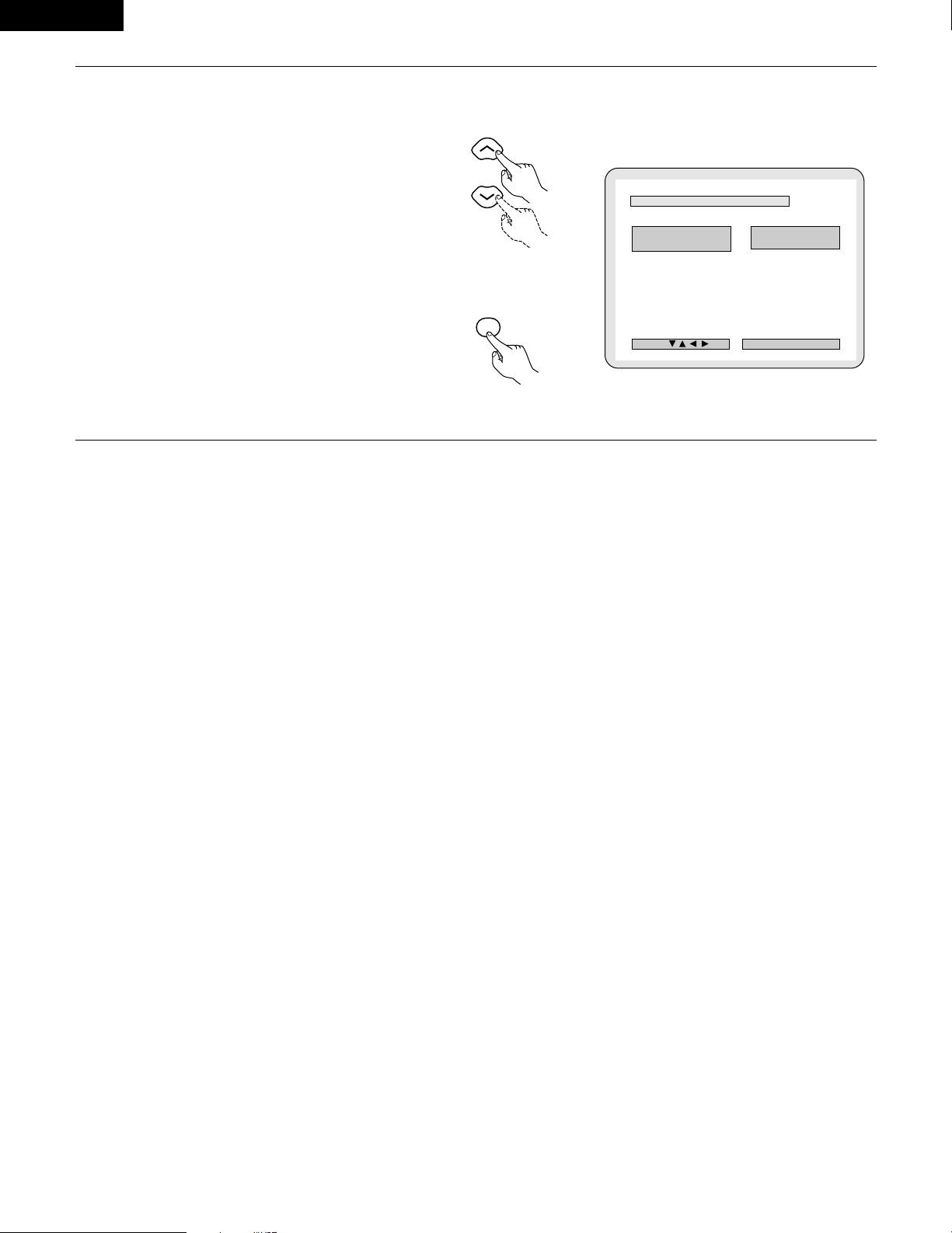
ENGLISH
78
4
2
“LPCM SELECT (96 kHz/48 kHz)” is selected.
• OFF (Factory default)
Make the selection when playing back to a decoder
DVDs that were recorded with this unit using linear
PCM 48 kHz/20/24 bit and 96 kHz modes. Note that
DVDs with Copyright Protection are converted to 48
kHz/16 bits and played back.
The same signal is output from the digital output
jacks.
• ON (96 kHz ÆÆ48 kHz)
DVDs that were recorded with linear PCM 48
kHz/20/24 bit and 96 kHz modes are all converted to
48 kHz/16 bits. Make this selection at the time of
digital recording.
✽
To exit the LPCM select mode
Press the ENTER button, you can go back to the
previous screen.
B
L PCM M SE L EC T
( 9 6 kH z -- > 48 kHz)
O FF
ON
DEC I SI ON: ENTER BUTTON
SELECT :
LPCM SELECT
Remote control unit
ENTER
Remote control unit
d
Page 79

ENGLISH
79
(
5)
“RATINGS” is selected
VOLUME
ENTER
BAND
MODE
MENU
FUNCTION
DISPLAY RETURN INPUT MODE SURROUND
TOP MENU
SETUP
SDB/TONE
MUTE
SURR.PARA
SUB TITLE ANGLE
AUDIO
SHIFT
CH.SELECT
CH
T.TONE
TU
PROG/DIRECT
REPEAT A-B
REPEAT RANDOM
DVD
TV/VCR
VOL
SLEEP
OFF
4
56
8
9
CLEAR
CALL
0
+10
7
STATUS
CDR/MD/TAPE
TUNER/TV/VCR
VCR POWERVCR POWER
TV POWERTV POWER
TV
NTSC/PAL
MEMO
POWER
CH
CH
2,3,4
4
2,3,4
1
3
Use the and cursor buttons to select the
desired setting, then press the
ENTER button.
• RATING LEVEL
Use this to restrict playback of adult DVDs you do not
want children to view. Note that even with adult
DVDs, viewing cannot be restricted unless the
restriction level is recorded on the disc.
It is however possible to disable playback of all DVDs.
• PASSWORD CHANGE
Use this to change the password.
The set’s password is set to “0000” by default.
✽
To exit the rating setup mode
Use the and cursor buttons to select “DVD
SETUP MENU”, then press
B
RA T I NG NG L EV E L
PAS SWOSWORD D CHANHANG E
NO NO L IM I T
XX XX
>
DVD SETUP MENU DVD SETUP MENU
DEC I SI ON: ENTER BUTTON
SELECT :
RAT INGS
Remote control unit
ENTER
Remote control unit
1
2
See page 71.
4
Use the and cursor buttons to select the
desired setting, then press the ENTER button.
2
When “RATING LEVEL” is selected.
• Level 0(LOCK ALL)
Select this to disable playback of all DVDs.
Use this for example to disable playback of adult
DVDs on which the rating level is not recorded.
• Level 1
Select this to play only DVDs for children. (Adult and
general audience DVDs cannot be played.)
• Level 2 to Level 8
Select this to play DVDs for general audiences and
children. Adult DVDs cannot be played.
• NO LIMIT (Factory default)
Select this to play all DVDs.
B
RA T ING NG L EV EL 0 (LOCK ALL)0 (LOCK ALL)
2
3
4
5
6
7
8
NO NO L IMI T
1
DEC I SI ON: ENTER BUTTON
SELECT :
RA T ING LEVEL
B
CUCUR REN T T PAS SWSWO RD
DEC I SI ON: ENTER BUTTON
PL EASE ENTER PASSWOR D
PASSWORD
Remote control unit
ENTER
d
Remote control unit
d
Page 80

ENGLISH
80
4
Use the number buttons to input a 4-digit password,
then press the ENTER button.
✽
Be sure to set the DVD mode using the remote
control mode selector buttons.
✽
The set's password is set to “0000" by default.
✽
Do not forget the password.
✽
The setting cannot be changed without inputting
the correct password.
2
3
4
56
8
9
0
+10
7
1
Remote control unit
Remote control unit
ENTER
B
CUCUR REN T T PAS SWSWO RD
DEC I SI ON: ENTER BUTTON
PASSWORD
XX XX
PRESS EN TER TO CONT INUE
✽
When the password has been forgotten or when a
RATING LEVEL setting change is suspended, press
the ENTER button several times and terminate the
rating setup mode.
2
When “PASSWORD CHANGE” is selected.
Use the number buttons to input a 4-digit
password, then press the ENTER button.
✽
Be sure to set the DVD mode using the remote
control mode selector buttons.
✽
Do not forget the password.
✽
The setting cannot be changed without
inputting the correct password.
✽
The set’s password is set to “0000” by default.
B
OL D D PA SSWSWOR D
NEW NEW PASSWSWO RD
CONCONF I RM M P ASSWSW ORD
DEC I SI ON: ENTER BUTTON
PL EASE ENTER OLD PASS WORD
PA SSWORD
B
OL D D PA SSWSWOR D
NEW NEW PASSWSWO RD
XX XX
CONCONF I RM M P ASSWSW ORD
DEC I SI ON: ENTER BUTTON
PL EASE ENTER NEW PASS WORD
PA SSWORD
B
OL D D PA SSWSWOR D
NEW NEW PASSWSWO RD
XX XX
XX XX
CONCONF I RM M P ASSWSW ORD
DEC I SI ON: ENTER BUTTON
PL EASE RE ENTER PASSWO RD
PA SSWORD
2
3
4
56
8
9
0
+10
7
1
Remote control unit
Remote control unit
ENTER
//
d
d
Page 81

ENGLISH
81
(6) “OTHER SETUP” is selected
1
2
3
See page 71.
Use the and cursor buttons to select the
desired setting, then press the ENTER button.
• CAPTIONS
Use this to set whether or not to display the closed
captions recorded on DVDs.
✽
To exit the other setup mode
Use the and cursor buttons to select “DVD
SETUP MENU”, then press the ENTER button.
• The screen returns to as it was in step 2.
VOLUME
ENTER
BAND
MODE
MENU
FUNCTION
DISPLAY RETURN INPUT MODE SURROUND
TOP MENU
SETUP
SDB/TONE
MUTE
SURR.PARA
SUB TITLE ANGLE
AUDIO
SHIFT
CH.SELECT
CH
T.TONE
TU
PROG/DIRECT
REPEAT A-B
REPEAT RANDOM
DVD
REMOCON MODE
STATUS
CDR/MD/TAPE
TUNER/TV/VCR
VCR POWER
TV POWER
NTSC/PAL
MEMO
POWER
2,3,4
2,3,4
1
B
CA PT I ONSONS OF F
>
DVD SETUP MENU DVD SETUP MENU
DEC I SI ON: ENTER BUTTON
SELECT :
OTHER SETUP
Remote control unit
Remote control unit
ENTER
a
4
Use the and cursor buttons to select the
desired setting, then press the ENTER button.
2
When “CAPTIONS” is selected:
• OFF (Factory default)
Select this when you do not want to display the
captions on the screen when playing DVDs
containing English captions.
• ON
Select this to display the captions on the screen
when playing DVDs containing English captions.
✽
To exit the captions mode
Press the ENTER button, you can go back to the
previous screen.
• The screen returns to as it was in step 2.
B
CAPT I ONS OF F
ON
DEC I SI ON: ENTER BUTTON
SELECT :
CAPT IONS
Remote control unit
Remote control unit
ENTER
a
NOTES:
•
An English caption decoder is required to display English
captions.
• DVDs with caption signals are indicated by the , ,
, mark.
English captions cannot be displayed when playing DVDs which
do not contain caption signals.
• The characters in which the captions are displayed (capital
letters, small letters, italics, etc.) depend on the DVD and cannot
be selected with this unit.
ENGLISH
Page 82

ENGLISH
82
21
LAST FUNCTION MEMORY
• This unit is equipped with a last function memory which stores the input and output setting conditions as they were immediately before the
power is switched off.
This function eliminates the need to perform complicated resettings when the power is switched on.
• The unit is also equipped with a back-up memory. This function provides memory storage when the power switch is off and with the power
cord disconnected.
22
INITIALIZATION OF THE MICROPROCESSOR
When the indication of the display is not normal or when the operation of the unit does not shows the reasonable result, the initialization of the
microprocessor is required by the following procedure.
1
Press the power button to set the
standby mode, then unplug the set’s
power cord from the wall power outlet.
2
Hold the following PLAY (1) button and STOP (2) button, and
plug the AC cord into the outlet.
3
Check that the entire display is flashing with an interval of
about 1 second, and release your fingers from the 2 buttons
and the microprocessor will be initialized.
NOTES:
• If step 3 does not work, start over from step 1.
• If the microprocessor is reset, all the buttons and the setup
settings are reset to the factory default values.
1
c 8 1:02:46
DVD
TONE
1 2 2
ON / STANDBY
Green
Page 83

ENGLISH
83
Check again before assuming the player is malfunctioning
2 Are all the connections correct ?
2 Are you following the instructions in the manual ?
2 Are the speakers and other components operating properly ?
If this unit does not seem to be functioning properly, check the table below. If this does not solve the problem, this unit may be damaged. Turn
off the power, unplug the power cord from the power outlet, and contact your store of purchase or nearest Denon sales office.
23
TROUBLESHOOTING
Symptom Cause Measures Page
DISPLAY not lit and sound not produced
when power switch set to on.
• Power cord not plugged in securely. • Check the insertion of the power cord plug. 8
DISPLAY lit but sound not produced.
• Speaker cords not securely connected.
• Improper position of the audio function
button.
• Volume control set to minimum.
• MUTING is on.
• Digital signals not input Digital input
selected.
• Connect securely.
• Set to a suitable position.
• Turn volume up to suitable level.
• Switch off MUTING.
• Input digital signals or select input jacks to
which digital signals are being input.
14
35
36
37
36
Monitor doesn't display an image.
•
Connections between the video output jack
of this unit and the input connector of the
monitor are incomplete.
•
The input setting of the monitor TV is
different.
•
The video signals of the various devices are
not uniform.
•
Check whether the connections are correct.
•
Set the input switching of the TV to the jack
to which the video input is connected.
•
Make settings uniform for either composite
video or S-video connectors.
9, 10, 12
—
10, 12
The program cannot be copied from DVD
to the VCR.
•
Almost all movie software contains a copy
prevention signal.
•
A copy cannot be made.
—
The subwoofer does not produce sound.
•
Power is not being supplied to the
subwoofer.
•
The subwoofer setting is made to "No" in
the setup.
•
The output of the subwoofer has not been
connected.
•
Switch on the power of the subwoofer.
•
Change the setting to “Subwoofer” in the
setup.
•
Make the proper connections.
—
26
14
The test tone is not output.
•
The surround mode is set to a mode other
than auto decode.
•
Set to auto decode.
40
This unit does not operate properly when
remote control unit is used.
• Batteries dead.
• Remote control unit too far from this unit.
• Obstacle between this unit and remote
control unit.
• Different button is being pressed.
• < and > ends of battery inserted in reverse.
•
The mode selection of the remote control is
not properly selected. The DVD mode, AV
mode, or audio mode is not properly
selected.
• Replace with new batteries.
• Move closer.
• Remove obstacle.
• Press the proper button.
• Insert batteries properly.
•
Press the remote control mode selection
button for the item you wish to operate. To
operate this unit, use with the DVD mode.
18
18
18
17
18
17
Remote control unit
Common problems when listening to the discs, tapes and FM broadcasts, etc.
ENGLISH
Page 84

ENGLISH
84
Symptom PageCheck
DVD operation
Playback does not start when PLAY
button is pressed.
Playback stops immediately.
—
6
7
• Is there condensation on the disc or player ? (Let stand for 1 or 2 hours.)
• Discs other than DVDs, video CDs and music CDs cannot be played.
• Disc is dirty. Wipe off the dirt.
Menu playback of video CD’s is not
possible.
—• Menu playback is not possible with anything but video CDs with playback control.
Picture is disturbed during the search
operation.
—• Some disturbance is normal.
Buttons do not operate. 33• Some operations are disabled for some discs.
No subtitles are displayed.
—
72, 73
• Subtitles are not displayed for DVDs not containing subtitles.
• Subtitles are turned off. Turn the subtitles setting on.
Audio (or subtitle) language does not
switch.
62
66
• The audio (or subtitle) language does not switch for discs which do not include multiple
audio (or subtitle) languages.
• For some discs the audio (or subtitle) language cannot be switched when the operation to
switch it is performed, but can be switched on the menu screens.
Angle does not switch.
64• The angle cannot be switched for DVDs which do not contain multiple angles. In some
cases multiple angles are only recorded for specific scenes.
Playback does not start when the title is
selected.
79, 80• Check the “RATINGS SETUP” setting.
The password for rating level has been
forgotten.
Reset all the DVD setting to Factory
Preset.
79, 80
• While the player is in the stop mode, hold the player's SKIP (
8
) button and the PAUSE
(
3
) button down simultaneously for longer than 3 seconds (until “INITIALIZE” disappears
from the TV monitor).
The lock will be released and the DVD all default settings and picture settings will return to
the default values.
The disc is not played with the audio or
subtitle language set as the default
setting.
62, 63• The disc does not play with the selected audio or subtitle language if that audio or subtitle
language is not included on that DVD.
Picture is not displayed in 4:3 (or 16:9). 75• Set the “TV ASPECT” default setting to the proper setting for the connected TV.
Menu screen messages for the desired
language do not display.
72, 73• Check the default setting for the disc language’s menu language.
Page 85

ENGLISH
85
24
SPECIFICATIONS
2 Audio section
• Power amplifier
Output power: Front: 35 W + 35 W (6 Ω/ohms, 1 kHz with 10% T.H.D.)
Center: 35 W (6 Ω/ohms, 1 kHz with 10% T.H.D.)
Surround: 35 W + 35 W (6 Ω/ohms, 1 kHz with 10% T.H.D.)
Output terminals: Front, Center, Surround: 6 ~ 16 Ω/ohms
• Analog
Input sensitivity / input impedance: 200 mV / 47 kΩ/kohms
Frequency response: 10 Hz ~ 70 kHz: +0, –3 dB (DIRECT mode)
S/N: 98 dB (DIRECT mode)
Rated output: 1.2 V (Subwoofer preout, 20 Hz)
• Digital
Digital input / output: Format — Digital audio interface
2 Video section
• Standard video jacks
Input / output level and impedance: 1 Vp-p, 75 Ω/ohms
• S-video jacks
Input / output level and impedance: Y (brightness) signal — 1 Vp-p, 75 Ω/ohms
C (color) signal — 0.286 Vp-p, 75 Ω/ohms
• Color component video jacks (DVD output)
Input / output level and impedance: Y (brightness) signal — 1 Vp-p, 75 Ω/ohms
C
B (blue) signal — 0.648 Vp-p, 75 Ω/ohms
CR (red) signal — 0.648 Vp-p, 75 Ω/ohms
2 Tuner section
[FM] (note: µV at 75 Ω/ohms, 0 dBf=1 x 10
–15
W) [AM]
Receiving Range: 87.50 MHz ~ 107.90 MHz 520 kHz ~ 1710 kHz
Usable Sensitivity: 1.5 µV (14.8 dBf) 20 µV
2 DVD section
Signal system: NTSC/PAL
Applicable discs: (1) DVD-Video discs
1-layer 12 cm single-sided discs, 2-layer 12 cm single-sided discs,
2-layer 12 cm double-sided discs (1 layer per side)
1-layer 8 cm single-sided discs, 2-layer 8 cm single-sided discs,
2-layer 8 cm double-sided discs (1 layer per side)
(2) Compact discs (CD-DA, Video CD)
12 cm discs, 8 cm discs
Audio output: Fixed output level: 2 Vrms, (CDR/TAPE, VCR OUT)
2 Clock, Timer section
Clock system: Power source synchronous system
Timer functions: Everyday timer (DVD or Tuner) : 1 setting
Sleep timer: maximum 120 min.
2 General
Power supply: AC 120 V, 60 Hz
Power consumption: 135 W (Standby 1.2 W)
Maximum external
dimensions: 434 (width) x 90 (height) x 415 (depth) mm (17.1” x 3.5” x 16.3”)
Mass: 9.4 kg (20.7 lbs)
2 Remote control unit: RC-902
Type: Infrared pulse
Power supply: DC 3 V, 2 “AA” (R06) batteries
ENGLISH
✽ Design and specifications are subject to change without notice in the course of product improvement.
This product incorporates copyright protection technology that is protected by method claims of certain U.S. patents and other intellectual
property rights owned by Macrovision Corporation and other rights owners. Use of this copyright protection technology must be authorized
by Macrovision Corporation, and is intended for home and other limited viewing uses only unless otherwise authorized by Macrovision
Corporation. Reverse engineering or disassembly is prohibited.
Page 86

86
FRANCAIS
2
INTRODUCTION
2
ACCESSORIES
Merci d’avoir porté votre choix sur l’ampli-syntoniseur surround DVD ADV-700 de Denon.
Ce remarquable composant a été fabriqué pour fournir une superbe écoute de sons d’ambiance avec des sources de cinéma domestique telles
que DVD, ainsi que pour assurer une formidable reproduction haute fidélité de vos sources musicales favorites.
Ce produit étant équipé d’une immense foule de caractéristiques, nous vous recommandons avant de commencer l’installation et l’utilisation de
l’appareil de bien lire le contenu de ce manuel avant de procéder.
TABLE OF CONTENTS
Check that the following parts are included in addition to the main unit:
q Mode d’emploi.................1 w
Certificat de garantie (pour l’Amérique du Nord uniquement)
…1 e Liste des centres d’entretien...1 r Télécommande
t Piles R6P/AA ...................2 y Antenne-cadre AM.......1 u Antenne intérieure FM…1 i Adaptateur d’antenne FM….....1 (RC-902)............…......1
o Cordon vidéo ...................1
rtyu
V
O
L
U
M
E
B
A
N
D
MODE
M
E
N
U
F
U
N
C
T
I
O
N
DISPLAY
RETURN
INPUT MODE
SURROUND
TOP MENU
SETUP
SDB/TONE
MUTE
SURR.PARA
SUB TITLE
ANGLE
AUDIO
S
H
I
F
T
CH.SELECT
CH
T.TONE
TU
P
R
O
G
/D
IR
E
C
T
R
E
P
E
A
T
A
B
REPEAT
RANDOM
D
V
D
T
V/VCR
CH
VOL
SLEEP
O
N
O
F
F
R
E
M
O
C
O
N
M
O
D
E
2
3
4
5
6
8
9
0
7
1
S
T
A
T
U
S
C
D
R
/
M
D
/
T
A
P
E
T
U
N
E
R
/
T
V
/V
C
R
VCR POWER
TV
POWER
TV
VCR
N
T
S
C
/
P
A
L
E
N
T
E
R
MUTE
O
N
2
3
4
5
6
C
L
E
A
R
CALL
0
M
E
M
O
POWER
CH
CH
CH
O
F
F
1
8
9
+
1
0
7
io
1
2
AVANT L‘UTILISATION
PRECAUTIONS D’INSTALLATION
Faire attention au points suivants avant d’utiliser cet appareil:
• Déplacement de l’appareil
Pour éviter des court-circuits ou des fils endommagés dans les
câbles de connexion, toujours débrancher le cordon d’alimentation,
et déconnecter les câbles de connexion entre tous les autres
composants audio lors du déplacement de l’appareil.
• Avant de mettre sous tension
Vérifier une nouvelle fois si toutes les connexions sont bonnes et
s’il n’y a pas de problèmes avec les câbles de connexion. Toujours
placer l’interrupteur de mise sous tension en position d’attente
avant de connecter et de déconnecter les câbles de connexion.
L’utilisation simultanée de cet appareil ou d’autres appareils
électroniques à microprocesseur avec un tuner ou un téléviseur peut
produire des parasites dans le son ou l’image.
Si cela se produit, prendre les mesures suivantes:
•
Installer cet appareil aussi loin que possible du tuner ou du téléviseur
.
• Eloigner les câbles d’antenne du tuner ou du téléviseur aussi loin
que possible du cordon d’alimentation et des câbles de connexion
d’entrée/sortie de cet appareil.
• Ce problème est fréquemment rencontré lors de l’utilisation
d’antennes intérieures ou de câbles d’arrivée de 300 Ω/ohms.
L’utilisation d’antennes extérieures et de câbles coaxiaux de 75
Ω/ohms est recommandée.
Pour permettre la dissipation de la chaleur, laisser un espace d’au
moins 10 cm entre le haut, l’arrière et les flancs de cet appareil et
le mur ou d’autres composants.
• Ranger ces instructions dans un endroit sûr
Après les avoir lues, ranger ces instructions en même temps que la
garantie dans un endroit sûr.
• Noter que les illustrations de ces instructions peuvent varier
de l’appareil actuel dans un but d’explication.
1
c 8 1:02:46
DVD
TONE
10 cm ou plus
10 cm ou plus
Mur
z AVANT L’UTILISATION ..............................................................................86
x PRECAUTIONS D’INSTALLATION ............................................................86
c PRECAUTIONS DE MANIPULATION........................................................87
v CARACTERISTIQUES................................................................................87
b DISQUES...................................................................................................88
n PRECATIONS DE MANIPULATION DES DISQUES ..................................89
m CONNEXIONS.....................................................................................90~97
, APPELLATION DES PIECES ET FONCTIONS ....................................98, 99
. UNITE DE TELECOMMANDE ........................................................100~103
⁄0 REGLAGE DU SYSTEME................................................................104~112
⁄1 LECTURE ........................................................................................113~116
⁄2 OPERATION....................................................................................117~119
⁄3 DOLBY / DTS SURROUND.............................................................120, 121
⁄4 LACTURE ACCOUSTIQUE (SURROUND) ......................................122~129
⁄5 SIMULATION DSP SURROUND.....................................................130~133
⁄6 ECOUTER RADIO ...........................................................................134, 135
⁄7 AFFICHAGE A L’ECRAN .........................................................................136
⁄8 UTILISATION DE L’AFFICHAGE A L’ECRAN ..................................137~148
⁄9 UTILISATION DE LA MINUTERIE...................................................149~152
¤0 CHANGER LES REGLAGES PAR DEFAUT (DVD) ..........................153~163
¤1 MEMOIRE DE DERNIERE FONCTION ...................................................164
¤2 INITIALISATION DU MICROPROCESSEUR............................................164
¤3 LOCALISATION DES PANNES........................................................165, 166
¤4 SPECIFICATIONS....................................................................................167
Page 87

87
FRANCAIS
3
PRECAUTIONS DE MANIPULATION
4
CARACTERISTIQUES
• Commutation de la fonction d’entrée lorsque les prises
d’entrée ne sont pas connectées
Un déclic peut être produit si la fonction d’entrée est commutée
lorsque rien n’est connecté aux prises d’entrée. Dans ce cas,
abaisser la commande MASTER VOLUME (volume de la gamme
entière) ou connecter des composants aux prises d’entrée.
• Mise en sourdine des prises PRE OUT, HEADPHONE et de la
borne SPEAKER
Les prises PRE OUT, HEADPHONE et les bornes SPEAKER sont
équipées d’un circuit de sourdine. Pour cette raison, les signaux de
sortie sont fortement réduits pendant plusieurs secondes après
que l’interrupteur de mise sous tension ait été allumé ou après le
changement de fonction d’entrée, de mode d’ambiance ou de toute
autre installation. Si le volume est augmenté pendant cet instant, la
sortie sera très élevée après l’arrêt du circuit de mise en sourdine.
Toujours attendre que le circuit de mise en sourdine se désactive
avant de régler le volume.
• Chaque fois que l’interrupteur de mise sous tension est en
position STANDBY, l’appareil est toujours connecté à une
tension de ligne secteur.
Toujours débrancher le câble pour aller, par exemple, en
vacances.
1. Décodeur Dolby Digital
Le Dolby Digital, un système numérique discret dans lequel les
différents canaux sont complètement indépendants, recrée des
champs acoustiques “en trois dimensions” (sons avec une
sensation de distance, de mouvement et de position) sans
diaphonie entre les canaux pour un effet plus réel. De plus, les 5
canaux (à part le canal 0,1 pour les effets de basse fréquence) ont
une plage de lecture qui s’étend sur 20 kHz, la même que pour les
CD, produisant ainsi un son plus expressif et plus limpide.
2. Décodeur Dolby Pro LogicII
Le Dolby Pro Logic II est un nouveau format pour la lecture de
signaux audio multicanaux et qui offre une amélioration par rapport
au Dolby Pro Logic traditionnel. Il peut être utilisé non seulement
pour décoder des sources enregistrées en Dolby surround mais
également pour des sources stéréo ordinaires en 5 canaux (avant
gauche/droit, centre et surround gauche/droit). De plus, différents
paramètres peuvent être réglés selon le type de source et le
contenu, de sorte à pouvoir régler le champ acoustique avec une
plus grande précision.
3. DTS (Digital Theater Systems)
Le mode DTS fournit jusqu’à 5.1 canaux de son surround haute
fidélité sur une plage étendue, à partir de sources telles que des
disques laser, des DVD et des disques musicaux spécialement
codés.
4. Le DSP haute performance simule 7 champs acoustiques
La lecture est possible dans 7 modes surround : Stéréo à 5 canaux,
Film mono, Arène rock, Club jazz, Jeu vidéo, Matrice et Virtuel.
Vous pouvez bénéficier d’une grande variété d’effets sonores pour
les différentes scènes de film et pour des sources de
programmes, même pour les sources stéréo autres que Dolby
surround.
5. Fonction mémoire personnalisée Plus
Cette fonction est une version perfectionnée de l’ancienne
mémoire personnalisée. Grâce à la mémoire personnalisée Plus,
l’appareil mémorise automatiquement les modes surround et les
modes d’entrée pour chacune des sources d’entrées séparées.
6. Télécommande avec fonction de pré-mémoire
Cet appareil est accompagné d’une télécommande équipée d’une
fonction de pré-mémoire. La télécommande contrôle les codes
pour les composants Denon ainsi que pour les magnétoscopes,
TV, etc. d’autres marques majeures et qui ont été mémorisés.
7. Amplificateur de puissance à 5 canaux
L’ADV-700 est équipé d’un amplificateur de puissance à 5 canaux
35 W + 35 W (6Ω/ohms, 1 kHz. T.H.D. 10%) permettant une
lecture surround à 5.1 canaux lors d’une utilisation avec le super
woofer.
8. De nombreuses fonctions pratiques
(1) Fonction sons multiples
Sélection de 8 langues audio maximum.
(Le nombre de langues proposées varie d’un DVD à l’autre.)
(2) Fonction sous-titres multiples
Sélection de 32 sous-titres maximum.
(Le nombre de langues proposées varie d’un DVD à l’autre.)
(3) Fonction angles multiples
L’angle de vue peut être modifié.
(Pour les DVD sur lesquels des angles multiples ont été
enregistrés.)
(4) Fonction de mise hors service de la lecture
Cette fonction peut être utilisée pour empêcher la lecture de
DVD n’étant pas appropriés pour les enfants.
Page 88

88
FRANCAIS
5
DISQUES
• Les types de disques énumérés dans le tableau ci-dessous peuvent être utilisés sur le ADV-700.
Les marques de disque sont indiquées sur les étiquettes ou boîtiers de disque.
2 La terminologie du disque
• Titres et chapitres (DVD-vídeo)
Les DVD-vídeo sont divisés en plusieurs grandes sections
appelées “Titres” et en sections plus petites appelées
“Chapitres”.
Des numéros sont attribués à ces sections. Ces numéros
sont appelés “Numéros de titre” et “Numéros de chapitre”.
• Les pistes (CD vidéo et audio)
Les CD vidéo et audio sont divisés en sections appelées
“pistes”.
Des numéros sont attribués à ces sections. Ces numéros
sont appelés “numéros de piste”.
Par exemple:
Par exemple:
1
Disques
utilisables
Marque (logo)
Signaux
enregistrés
Dimension
du disque
DVD-vidéo
DVD-audio
(REMARQUE 1)
Audio numérique
+ vidéo
numérique
(MPEG2)
12 cm
8 cm
12 cm
8 cm
12 cm
8 cm
Audio numérique
+ vidéo
numérique
(MPEG1)
Audionumérique
CD Vidéo
CD
CD-R
CD-RW
(REMARQUE 2)
Recordable
ReWritable
Titre 1
Chapitre 1 Chapitre 2 Chapitre 3 Chapitre 1 Chapitre 2
Titre 2
Piste 1 Piste 2 Piste 3 Piste 4 Piste 5
2 Les types de disques suivants ne peuvent pas être lus sur
le ADV-700:
• Les DVD avec des nombres de région autres que “1” ou
“ALL” (TOUS)
• Les disques DVD audio (REMARQUE 1)
• DVD-R/ -RW /+RW
• Les DVD-ROM/RAM
• CVD
• SVCD
• Les CD-ROM (Seul les fichiers MP3 peuvent être joués.)
• Les VSD
• Les CDV (Seule la bande son peut être lue)
• Les CD-G (Seul le son est reproduit)
• Les CD photo (Ne jamais lire ce type de disque sur le ADV-
700.)
✽ Toute tentative de lecture de CD photo risque d’endommager
les données du disque.
REMARQUE 1: Seules les sections vidéo conformes à la norme
vidéo DVD peuvent être jouées.
REMARQUE 2: Suivant la qualité d’enregistrement, certains CD-
R/RW ne peuvent être joués.
• Commande de lecture (CD vidéo)
Les CD vidéo comportant la mention “Menu de commande”
(“playback control”) sur le disque ou le boîtier possèdent
une fonction permettant d’afficher des menus sur l’écran de
télévision pour sélectionner les pistes ou afficher des
informations, etc., en mode interactif.
Dans ce manuel, la lecture de CD vidéo faisant appel à de
tels menus est appelée “Lecture par menus”.
Les CD vidéo avec menus de commande peuvent être
utilisés sur le ADV-700.
REMARQUE:
• Ce lecteur DVD est conçu et fabriqué pour
prendre en compte les informations de
gestion de région (Region Management
Information) enregistrées sur les disques
DVD.
Ce lecteur vidéo DVD ne peut lire que les
disques DVD dont le numéro de région est
identique au sien.
Le numéro de région de ce lecteur vidéo
DVD est le 1.
Page 89

89
FRANCAIS
6
PRECAUTIONS DE MANIPULATION DES DISQUES
Disques
Seuls les disques de marques énumérées page 88 peuvent être
joués sur le ADV-700.
Remarque, les disques de forme particulière (disques en forme
de cœur, disques hexagonaux, etc.) ne peuvent pas être lus sur le
ADV-700. Ne pas tenter leur lecture car ils peuvent endommager
le lecteur.
Précautions de manipulation des disques
• Eviter toute empreinte digitale, graisse ou salissure sur les
disques.
• Prendre particulièrement soin de ne pas rayer les disques en
les sortant de leur boîtier.
• Ne pas tordre les disques.
• Ne pas chauffer les disques.
• Ne pas agrandir le trou central.
• Ne pas écrire sur les étiquettes (imprimées) de disque avec un
stylo à bille ou un crayon.
• Des gouttelettes de l’eau de condensation peuvent se former
sur la surface si le disque est soudainement déplacé d’un
endroit froid à un endroit chaud. Ne pas utiliser de sèchecheveux, etc., pour sécher le disque.
Précautions de rangement des disques
• Toujours éjecter les disques une fois la lecture terminée.
• Remettre les disques dans leur boîtier pour les protéger de la
poussière, des rayures et des déformations.
• Ne pas placer les disques dans les endroits suivants :
1. Exposés longtemps au soleil
2. Exposés à l’humidité ou à la poussière
3. Exposés à la chaleur d’appareils de chauffage, etc.
Précautions lors du chargement des disques
• Charger un seul disque à la fois. L’empilage de disques les uns
sur les autres peut les abîmer ou les rayer.
• Charger les disques de 8 cm de manière sûre dans le guide de
disque, sans adaptateur. Si le disque n’est pas mis en place
correctement, il peut glisser hors du guide et bloquer le tiroir du
disque.
• Faire attention aux doigts quand le tiroir de disque se referme.
• Ne pas mettre autre chose que des disques dans le tiroir de
disque.
• Ne pas charger de disques fêlés, déformés ou réparés avec de
l’adhésif, etc.
• Ne pas utiliser de disques s’ils portent du ruban adhésif, si une
partie de la colle de l’étiquette est exposée, si l’étiquette a été
décollée. De tels disques peuvent rester coincés à l’intérieur du
lecteur et causer des dommages.
Manipulation des disques
Eviter de toucher la surface du disque lors du chargement et
déchargement.
Nettoyage des disques
2
Les empreintes digitales ou salissures sur le disque peuvent
entamer la qualité du son et de l’image ou causer des
coupures lors de la lecture. Enlever toute empreinte de doigt
ou salissures.
2
Utiliser un nécessaire de nettoyage de disque disponible dans
le commerce ou un chiffon doux pour nettoyer toute
empreinte de doigt ou salissures.
Prendre soin de pas laisser
d’empreintes digitales sur
la face des données (le
côté qui brille comme un
arc-en-ciel).
Nettoyer avec précaution à
partir du centre vers l’extérieur.
Ne pas faire de mouvement
circulaire.
REMARQUE:
• Ne pas utiliser d’aérosol pour disque ou antistatique. Ne
pas utiliser non plus de solvant chimique volatile tel que
le benzène ou le dissolvant.
Aérosol
pour
disque
Dissolvant Benzène
Page 90

90
FRANCAIS
VIDEO
MON.OUT
S VIDEO
IN IN ININ OUT
TV/DBS
V.AUX
VCR
R
L
AUDIO
IN OUT IN IN ININ OUT
V.AUXTV/DBS VCR
CDR/
TAPE
PRE OUT
SUB WOOFER
IN IN OUT
V.AUXTV/DBS
(OPTICAL)
DIGITAL
SPEAKER SYSTEMS
6 16
R
L
R
L
IMPEDANCE
CENTER SURROUNDFRONT
MON.OUT
Y CB CR
AM
FM COAX. 75
LOOP
ANT.
COMPONENT VIDEO OUT
OPTICAL
IN
OUTPUT
L
R
INPUT
LR
L
R
R
L
L
R
L
R
B
7
CONNEXIONS
• Ne pas brancher le cordon CA avant d’avoir effectuer toutes les
connexions.
• S’assurer de connecter les canaux gauche et droit correctement (le
gauche à gauche et le droit à droite).
• Insérer fermement les prises. Des connexions inachevées
risquent de générer du bruit.
• Noter que le fait de lier les cordons à fiches de jack mâles
ensemble ou de les placer à proximité d’un transformateur de
puissance entraînera un bourdonnement ou d’autres bruits.
• Du bruit ou un bourdonnement risque de se produire si le matériel
audio connecté est utilisé indépendamment sans que cet appareil
ait été mis sous tension. Le cas échéant, activer cet appareil.
(1) Brancher les composants audio
• Lors des connexions, se référer également aux instructions de fonctionnement des autres composants.
Prise subwoofer
Connecter le subwoofer de l’amplificateur interne à
la borne du subwoofer. (Se reporter à la page 96.)
•
Réaliser des enregistrements numériques avec un enregistreur numérique
(Enregistreur CD, enregistreur MD, etc.) lors de la lecture de sources Dolby Digital
96 kHz et PCM sur ce lecteur de DVD.
•
Choisir le réglage par défaut “AUDIO SETUP” comme indiqué ci-dessous. (Voir
page 159,160.
)
• “DIGITAL OUT” → “PCM”
“LPCM SELECT
”
→ “ON”
Le fait de lire des DVD avec un réglage inapproprié risque de causer un bruit qui
pourrait endommager vos oreilles ou les enceintes.
CORDON CA
CA 120 V, 60 Hz
Brancher un enregistreur
Connexions pour l’enregistrement:
Brancher les prises d’entrée d’enregistrement du magnétophone (LINE IN ou REC)
aux prises d’enregistrement de cassette de cet appareil (CDR/TAPE OUT) à l’aide
des cordons à fiches de jack mâles.
Connexions pour la lecture:
Brancher les prises de sortie de lecture du magnétophone (LINE OUT ou PB) aux
prises de lecture de cassette de cet appareil (CDR/TAPE IN) à l’aide des cordons à
fiches de jack mâles.
Enregistreur CD, enregistreur MD
ou lecteur de cassette
Acheminer les cordons de connexion, etc. de sorte qu’ils
n’obstruent pas les orifices prévus pour la ventilation.
Brancher les prises DIGITAL(optiques)
Les utiliser pour des connexions avec le matériel audio avec sortie numérique (optique).
REMARQUES:
• Utiliser des câbles optiques pour les connexions optiques, en prenant soin de retirer la coiffe avant d’effectuer la connexion.
REMARQUE:
•
Les numéros des plages ne seront peut être pas ajoutés automatiquement lors
de l’enregistrement numérique de CD lus à partir du ADV-700 et vers un
enregistreur connecté.
• Lors d’enregistrements numériques sur un enregistreur CD, choisir le réglage
d’enregistrement manuel de l’enregistreur CD et ajouter les numéros de plages
(signes de plages) manuellement au fur et à mesure de l’enregistrement.
• Lors d’enregistrements numériques sur un enregistreur MD, utiliser la fonction
d’édition une fois que l’enregistrement est terminé afin de séparer les plages.
Page 91

Connexions entrée/sortie vidéo:
• Brancher la prise de sortie vidéo du magnétoscope (VIDEO OUT) à la prise (jaune) VCR IN,
et la prise d’entrée vidéo du magnétoscope (VIDEO IN) à la prise (jaune) VCR OUT à l’aide
des cordons à fiches de jack mâles coaxial vidéo de 75 Ω/ohms..
Brancher les prises de sortie audio
• Brancher les prises de sortie audio du magnétoscope (VIDEO OUT) aux prises VCR IN et
les prises d’entrée audio du magnétoscope (AUDIO IN) aux prises VCR OUT à l’aide des
cordons à fiches de jack mâles
..
AUDIO
AUDIO
VIDEO
VIDEO
MONITOR OUT
•
B
rancher la prise d’entrée
vidéo de la TV (VIDEO
INPUT) sur la prise
MONITOR OUT à l’aide
d’un cordon à fiches de jack
mâles coaxial vidéo de 75
Ω/ohms.
VIDEO
91
FRANCAIS
VIDEO
MON.OUT
S VIDEO
IN IN ININ OUT
TV/DBS
V.AUX
VCR
R
L
AUDIO
IN OUT IN IN ININ OUT
V.AUXTV/DBS VCR
CDR/
TAPE
PRE OUT
SUB WOOFER
IN IN OUT
V.AUXTV/DBS
(OPTICAL)
DIGITAL
SPEAKER SYSTEMS
6 16
R
L
R
L
IMPEDANCE
CENTER SURROUNDFRONT
MON.OUT
YCB CR
AM
FM COAX. 75
LOOP
ANT.
VIDEO
OUT
AUDIO
OUT
L
R
VIDEO
OUT
INLR
OUT IN
L
R
AUDIO
OUT
OPTICAL
VIDEO
OUT
AUDIO
OUT
L
R
OUT
OPTICAL
VIDEO
IN
L
R
R
L
R
L
L
R
L
R
L
R
B
B
L
R
R
L
(2) Brancher les composants vidéo
• Pour connecter le signal vidéo, effectuer le branchement à l’aide d’un câble de signal vidéo de 75 (Ω/ohms. L’utilisation d’un câble inapproprié
pourrait réduire la qualité de la vidéo.
• Lors des connexions, se référer également aux instructions de fonctionnement des autres composants.
Syntoniseur TV ou DBS
Syntoniseur CS
Brancher un syntoniseur TV/DBS
TV/DBS
• CBrancher la prise de sortie vidéo du syntoniseur
TV ou DBS (VIDEO OUTPUT) à la prise)
(jaune) TV/DBS IN en utilisant un cordon à fiches
de jack mâles coaxial vidéo de 75 (Ω/ohms.
• CBrancher les prises de sortie audio du
syntoniseur TV ou DBS (AUDIO OUTPUT) aux
prises d’entrée TV/DBS IN en utilisant la
fiche de jack mâle.
• Pour les dispositifs avec sorties numériques
optiques, brancher la borne de sortie numérique
à la borne DIGITAL TV/DBS IN du ADV-700 à
l’aide d’un câble de transmission optique.
AUDIO
VIDEO
Ecran de TV
Brancher un syntoniseur CS
V.AUX
• Brancher la prise de sortie vidéo du syntoniseur CS (VIDEO
OUTPUT) à la prise (jaune) V.AUX IN à l’aide d’un
cordon à fiches de jack mâles coaxial vidéo de 75 Ω/ohms.
•
Brancher les prises de sortie audio du syntoniseur CS (AUDIO OUTPUT)
aux prises V.AUX IN à l’aide des cordons à fiches de jack mâles.
• Pour les dispositifs avec sorties numériques optiques, brancher
la borne de sortie numérique à la borne DIGITAL V.AUX.IN du
ADV-700 à l’aide d’un câble de transmission optique.
AUDIO
VIDEO
Remarque concernant la connexion des prises
d’entrée numérique
•
Uniquement les signaux audio sont envoyés aux prises
d’entrées numériques.
• Utiliser des câbles optiques pour les connexions
optiques en prenant soin de retirer la coiffe avant
d’effectuer la connexion.
Lecteur de vidéo
Brancher un magnétoscope
Page 92

92
FRANCAIS
VIDEO
MON.OUT
S VIDEO
IN IN ININ OUT
TV/DBS
V.AUX
VCR
R
L
AUDIO
IN OUT IN IN ININ OUT
V.AUXTV/DBS VCR
CDR/
TAPE
PRE OUT
SUB WOOFER
IN IN OUT
V.AUXTV/DBS
(OPTICAL)
DIGITAL
L
MON.OUT
Y CB CR
COMPONENT VIDEO OUT
S-VIDEO
IN
S-VIDEO
OUT
S-VIDEO
OUT
S-VIDEO INS-VIDEO
OUT
B
B
(3) Brancher un composant vidéo équipé de prises S-vidéo
• Lors des connexions, se référer également aux instructions de fonctionnement des autres composants.
• Une remarque concernant les prises d’entrée S
Les sélecteurs d’entrée pour les entrées S et les entrées de prises jack fonctionnent conjointement.
• Précautions à prendre lors de l’utilisation de prises S
Les prises S de cet appareil (entrée et sortie) et les prises jacks vidéo (entrée et sortie) ont des structures de circuit indépendantes, de sorte
que les entrées de signaux vidéo des prises S ne sont envoyés que par les sorties de prises vidéo et les signaux vidéo reçus par les prises jack
ne sont envoyés que par les sortie de prises jack.
Lors de la connexion de cet appareil avec du matériel équipé de prises S, veuillez garder ceci à l’esprit et effectuer les connections selon les
manuels d’instructions du matériel.
Brancher un écran de TV
SORTIE ECRAN
• CBrancher l’entrée S-vidéo de la TV (SVIDEO INPUT) sur la prise
MONITOR OUT à l’aide d’un câble de
connexion S-vidéo.
S-VIDEO
Ecran de TV
Brancher un syntoniseur TV/DBS
• Brancher la prise de sortie Svidéo du syntoniseur TV ou DBS
(S-VIDEO OUTPUT) à la prise
TV/DBS IN à l’aide
d’un câble de connexion Svidéo.
S-VIDEO
Brancher un syntoniseur CS
• Brancher la prise de sortie S-vidéo du
syntoniseur CS (S-VIDEO OUTPUT) à la
prise V.AUX. IN à l’aide d’un
câble de connexion de prise stéréo.
S-VIDEO
Syntoniseur TV ou DBS
Brancher les lecteurs de vidéo
• Brancher la prise de sortie S-vidéo du lecteur de vidéo (SOUT) à la prise VCR IN et la prise d’entrée Svidéo du lecteur vidéo (S-IN) à la prise VCR OUT
à l’aide de câbles de connexion de prises stéréo.
S-VIDEO
S-VIDEO
Lecteur de vidéo
Brancher les entrées et les sorties audio des
composants en suivant les instructions page 91.
• Brancher les sorties vidéo de cet appareil directement sur la
TV. Ne pas les connecter par l’intermédiaire d’un
magnétoscope. Certains disques contiennent des signaux
d’interdiction de reproduction. Si de tels disques sont lus par
un magnétoscope, le système d’interdiction de reproduction
risque de déformer l’image.
•
Régler la fonction “TV TYPE” dans “VIDEO SETUP” dans “
DVD SETUP” afin de correspondre au format vidéo de votre
TV. Lorsque la TV est NTSC, le format est réglé sur NTSC
.
REMARQUES:
Syntoniseur CS
Page 93

93
FRANCAIS
1
4
2
3
R
L
L
R
YCB CR
(4) Brancher les bornes de l’antenne
ANTENNE
INTERIEURE FM
(Fournie)
CABLE
COAXIAL
75 Ω/ohms
ANTENNE FM
ANTENNE
INTERIEURE FM
(Fournie)
CADRE
D’ANTENNE AM
(Fourni)
ANTENNE
EXTERIEURE AM
MASSE
Ensemble d’antenne-cadre AM
Connecter aux
bornes d’antenne AM.
Défaire le noeud en
vinyle et sortir la
ligne de connexion.
Plier dans la
direction inverse.
a. Avec l’antenne sur
le haut de toute
surface stable.
b.Avec l’antenne
fixée au mur.
Monter
Trou d’installation
Monter au mur, etc.
Connexion des antennes AM
1. Appuyer sur
le levier.
2. Insérer le conducteur. 3. Ramener le
levier.
Remarque à l’installateur de système de télédistribution:
Ce rappel est fourni pour attirer l’attention de l’installateur de système
de télédistribution sur l’article 820-40 du NEC qui fournit des directives
sur une bonne mise à la masse et, en particulier, spécifie que la terre
du câble doit être connectée au système de mise à la masse du
bâtiment, aussi près du point d’entrée de câble que possible
.
Remarques:
• Ne pas connecter simultanément deux antennes FM.
• Même si une antenne extérieure AM est utilisée, ne pas
déconnecter l’antenne-cadre AM.
• Vérifier que les bornes de fil d’antenne-cadre AM ne touchent
pas les parties métalliques du panneau.
ADAPTATEUR
D’ANTENNE FM
(Fourni)
• Une prise de câble d’antenne FM de type F peut être connectée directement.
• Si la prise du câble de l’antenne FM n’est pas de type F, effectuer la connexion, à l’aide de l’adaptateur d’antenne fourni.
14mm
9mm
14mm
19mm
5mm
5mm
5C-2V3C-2V
5C-2V
Adaptateur d’antenne FM
75 Ω/ohms COAXIAL CABLE
Ouvrir le couvercle
ADAPTATEUR D’ANTENNE
RETIRER
ATTACHE
ATTACHE
ATTACHE
ATTACHE
TIRER
TIRER
SHUT
SHUT
LOOP
ANT.
R
AM
FRONT
FM COAX. 75
IMPEDANCE
L
6 16
SPEAKER SYSTEMS
CENTER SUR
R
Page 94

94
FRANCAIS
VIDEO
MON.OUT
S VIDEO
IN IN ININ OUT
TV/DBS
V.AUX
VCR
R
L
AUDIO
IN OUT IN IN ININ OUT
V.AUXTV/DBS VCR
CDR/
TAPE
PRE OUT
SUB WOOFER
IN IN OUT
V.AUXTV/DBS
(OPTICAL)
DIGITAL
SPEAKER SYSTEMS
6 16
R
L
R
L
IMPEDANCE
CENTER SURROUNDFRONT
MON.OUT
Y CB CR
AM
FM COAX. 75
LOOP
ANT.
COMPONENT VIDEO OUT
COMPONENT VIDEO IN
C
B CRY
(5) Connexion avec une TV ou un écran équipé de connecteurs d’entrée de composants.
• Lors des connexions, se référer également aux instructions de fonctionnement des autres composants.
• Les signaux vidéo reçus par l’entrée VIDEO (jaune) et les prises d’entrée S-vidéo ne sont pas envoyés vers les prises vidéos de différence des
couleurs (composants).
Brancher un écran TV
Prise MONITOR OUT (sortie écran)
• Brancher les prises d’entrée vidéo
(composant) de différence des couleurs
de la TV (ENTREE VIDEO DES
COMPOSANTS) à la prise COMPONENT
MONITOR OUT à l’aide de cordons à
fiches de jack mâles vidéo coaxial de 75
Ω/ohms.
Connecteurs de sortie des composants couleur (CR, C
B et Y)
Les signaux rouge (C
R), bleu (C
B) et de luminosité (Y) sont transmis séparément pour obtenir une reproduction
plus fidèle des couleurs.
• Les connecteurs d’entrée de composantes couleur peuvent être repérés différemment sur certaines TV ou
certains moniteurs (P
R, PB et Y/R-Y, B-Y et Y/CR, CB et Y, etc.). Pour plus de détails, consulter les manuels
d’utilisation de ces appareils.
REMARQUES:
• Utilisez les trois cordons vidéo (disponibles dans le commerce) pour brancher les connecteurs de sortie par composants de couleur
du ADV-700 sur une télévision ou un moniteur.
• Régler la fonction « TV TYPE» dans « VIDEO SETUP» dans « DVD SETUP» afin de correspondre au format vidéo de votre TV.
Lorsque la TV est NTSC, le format est réglé sur NTSC.
Page 95

95
FRANCAIS
(6) Sortie du son des connecteurs de sorties audio numériques de cet appareil
2 Lorsqu’un disque est lu avec le ADV-700
Se référer
à la page
DVD video
DVD audio
(Partie vidéo
uniquement)
Format d’enregistrement
audio
Dolby Digital
PC : MARCHE
CD vidéo
PC : ARRET
DTS
48 kHz
• Le son MIC linéaire est le signal de format d’enregistrement utilisé pour les CD musicaux.
Alors que les signaux sont enregistrés à 44,1 kHz/16 bits pour les CD musicaux, en ce qui concerne les DVD, ils sont enregistrés de
48 kHz/16 bits à 96 kHz/24 bits, fournissant ainsi une meilleure qualité sonore que les CD musicaux.
CD musical
CD MP3
PCM linéaire
96 kHz
32 ~ 48 kHz/16 bits PCM
44,1 kHz/16 bits PCM
44,1 kHz/16 bits PCM
Mode de conversion LPCM : OFF
Mode de conversion LPCM : OFF
MPEG 1
PCM linéaire
MP 3
Mode de conversion LPCM : ON
Mode de conversion LPCM : ON
Mode de conversion LPCM : OFF
Sortie numérique : Conversion PCM
Sortie numérique : Normal
Sortie numérique : Conversion PCM
Sortie numérique : Normal
Réglages
96 kHz PCM (lorsqu’il n’y a pas protection contre la reproduction)
48 kHz/16 bits PCM (lorsque protégé contre la
reproduction)
48 kHz/16 bits PCM
48 kHz/16 bits PCM
48 kHz/16 ~24 bits PCM
Flux de bits DTS
Flux de bits DTS
2 canaux données PCM (48 kHz/16bits)
Flux de bits Dolby Digital
Sorties de données audio numériques
159
160
Page 96

96
FRANCAIS
(7) Connexions des enceintes
•
Utiliser les cordons d’enceintes avec le centre du fil tortillé et un diamètre de 0,6 à 1,5 mm.
Ne jamais utiliser de cordon plus épais que 1,5mm ou des cordons à fil
unique car ils risqueraient d’abîmer les bornes des enceintes.
• Be sure to interconnect the polarities of the terminals on the speakers and
main unit (≈ to ≈, √ to √).
• Lors des connexions, s’assurer qu’aucun fil central des cordons d’enceintes
ne dépassent ni ne touchent les bornes voisines, les autres cordons
d’enceintes ou la face arrière.
• Les enceintes ayant une impédance de 6 à 16 Ω/ohms peuvent être
connectées pour être utilisées comme des enceintes acoustiques
d’ambiance et centrale.
Connexion des bornes d’enceintes
1. Appuyer sur le levier. 2. Insérer le cordon 3. Ramener le levier.
Connexions
• Lors des connexions, se référer également aux instructions de fonctionnement des autres composants.
REMARQUE:
NE JAMAIS toucher les bornes des enceintes lorsque l’appareil est sous
tension.
Ceci pourrait causer une décharge électrique.
• Le circuit protecteur peut être activé si l’appareil fonctionne pendant de
longues périodes, à un volume élevé et lorsque des enceintes avec une
impédance inférieure à l’impédance spécifiée sont connectées.
• Précautions à prendre lors de
la connexion des enceintes
Si une enceinte est placée près
d’un téléviseur ou d’un moniteur
vidéo, les couleurs de l’écran
peuvent être perturbées par le
magnétisme de l’enceinte. Si
cela se produit, déplacer
l’enceinte vers un endroit où cet
effet ne se produit pas.
VIDEO
MON.OUT
S VIDEO
IN IN ININ OUT
TV/DBS
V.AUX
VCR
R
L
AUDIO
IN OUT IN IN ININ OUT
V.AUXTV/DBS VCR
CDR/
TAPE
PRE OUT
SUB WOOFER
IN IN OUT
V.AUXTV/DBS
(OPTICAL)
DIGITAL
SPEAKER SYSTEMS
6 16
R
L
R
L
IMPEDANCE
CENTER SURROUNDFRONT
MON.OUT
Y CB CR
AM
FM COAX. 75
LOOP
ANT.
COMPONENT VIDEO OUT
(L) (R)
(L) (R)
ENCEINTES AVANT ENCEINTE CENTRALE
ENCEINTES SURROUND
SUBWOOFER
Prise de connecteur pour
subwoofer avec amplificateur
intégré (super woofer), etc.
Page 97

97
FRANCAIS
• Cet appareil est équipé d’un circuit de protection haute vitesse. Le but de ce circuit est de protéger les enceintes contre des
situations telles que lorsque la sortie de l’amplificateur de puissance est accidentellement court-circuitée et qu’un fort
courant passe, lorsque la température avoisinant l’appareil devient anormalement élevée, ou lorsque l’appareil est utilisé à
puissance élevée pendant une longue durée, ce qui entraîne une augmentation de température extrême.
Lorsque le circuit de protection est activé, la sortie des enceintes est coupée, et la DEL du témoin d’alimentation clignote.
Dans ce cas, suivre ces étapes: toujours couper l’alimentation de cet appareil, vérifier s’il y a des défauts de connexion des
cordons d’enceintes ou des câbles d’entrée, et attendre que l’appareil refroidisse, s’il est très chaud. Améliorer la ventilation
autour de l’appareil, et remettre sous tension.
Si le circuit de protection est à nouveau activé bien qu’il n’y ait pas de problème de câblage ou de ventilation autour de
l’appareil, couper l’alimentation, et contacter un centre d’entretien DENON.
Circuit de protection
• Le circuit de protection peut être activé si l’appareil est utilisé pendant une longue durée à un volume élevé lorsque des
enceintes d’une impédance inférieure à celle spécifiée (par exemple, enceintes ayant une impédance inférieure à 4 Ω/ohms)
sont connectées. Si le circuit de protection est activé, la sortie des enceintes est coupée. Couper l’alimentation de l’appareil,
attendre qu’il refroidisse, améliorer la ventilation autour de lui, puis remettre sous tension.
Remarque sur l’impédance des enceintes
Page 98

98
FRANCAIS
8
APPELLATION DES PIECES ET FONCTION
Face avant
• Pour plus de détails sur les fonctions de ces pièces, se référer aux pages indiquées entre parenthèses ( ).
FUNCTION
/SELECT
MASTER VOLUME
ON / STANDBY
SURROUND
MODE
SDB/TONE
TIMER/SET
STATUS
OPEN/CLOSE
PHONES
DVD SURROUND
RECEIVER
ADV-700
1
c 8 1:02:46
DVD
TONE
- TUNING +
BAND
1617 1415 13
1 2 3 4 5 6 7
10 11 12
8 9
q
Touche d’alimentation (ON/STANDBY)...................................(113)
w
Prise écouteurs (PHONES).....................................................(119)
e
Capteur du signal de télécommande (REMOTE SENSOR)....(100)
r
Touche ouverture/fermeture (5 OPEN/CLOSE).....................(113)
t
Touche lecture (1).................................................................(114)
y
Touche pause (3) ...................................................................(115)
u
Touche bande syntoniseur / stop (2/BAND)...................(115,134)
i
Touche de balayage /syntonisation
– (8/TUNING –)....(116,134)
o
Touche de balayage / syntonisation
+(9/TUNING +)..(116,134)
!0
Commutation de la fonction d’entrée/molette de sélection
(FUNCTION/SELECT).....................................(117~119, 149~151)
!1
Touche TIMER/SET (miniterie/réglage) ..........................(149~151)
!2
Commande MASTER VOLUME.............................................(118)
!3
Touche SDB/TONE .................................................................(119)
!4
Touche SURROUND MODE...................................................(117)
!5
Touche STATUS ......................................................................(118)
!6
Affichage
!7
Plateau à disque .....................................................................(113)
Page 99

99
FRANCAIS
VOLUME
ENTER
BAND
MODE
MENU
FUNCTION
DISPLAY RETURN INPUT MODE SURROUND
TOP MENU
SETUP
SDB/TONE
MUTE
SURR.PARA
SUB TITLE ANGLE
AUDIO
SHIFT
CH.SELECT
CH
T.TONE
TU
PROG/DIRECT
REPEAT A-B
REPEAT RANDOM
DVD
TV/VCR
CH
VOL
SLEEP
ON
OFF
REMOCON MODE
2
3
4
56
8
9
CLEAR
CALL
0
+10
7
1
STATUS
CDR/MD/TAPE
TUNER/TV/VCR
VCR POWER
TV POWER
TV
VCR
NTSC/PAL
MEMO
POWER
CH
CH
CH
Télécommande
• Pour plus de détails sur les fonctions de ces pièces, se référer aux pages indiquées entre parenthèses ( ).
• Certaines touches de la télécommande ont deux fonctions.
Les fonctions sont commutées en utilisant les touches de sélecteur de mode de la télécommande (CDR/MD/TAPE, TUNER/TV/VCR et DVD).
Après avoir pressé une de ces touche, la fonction ne sera commutée qu’après avoir appuyé sur une autre touche du sélecteur de mode de la
télécommande. Les modes de la télécommande changent comme décrit ci-dessous lorsque les touches sont activées.
.Touche POWER ON/OFF ....................(113)
Touche éffacer CLEAR. ........................(140)
Touche rappel CALL.............................(140)
Touche ANGLE.....................................(146)
Touche RANDOM.................................(141)
Touche REPEAT....................................(138)
Touches du système.....................(102,103)
Touche SLEEP......................................(152)
Touche de sélection mode
SURROUND .........................................(117)
Touche de sélection
INPUT MODE .......................................(117)
Touche de sélection FUNCTION ..........(117)
Touche ENTER .....................................(104)
Touches de contrôle du volume principal
...(118)
Touche MUTE.......................................(119)
Touche NTSC/PAL ..................................(92)
Touche STATUS....................................(118)
Touche TOP MENU..............................(147)
Touche de paramètre surround
(SURR.PARA)................(123~127,131~133)
Touche de sélection SDB/TONE ..........(119)
Touches de sélection du mode de la
télécommande
• Les touches indiquées avec sont des touches de fonctionnement du DVD. Celles-ci peuvent
être utilisées lorsque le mode DVD est sélectionné à l’aide des touches de sélection de mode de la
télécommande.
• Les touches du système (*) sont des touches dont la fonction varie selon le mode sélectionné à
l’aide des touches de sélection de la télécommande..
• Les autres touches sont les touches de fonctionnement de l’amplificateur surround, lesquelles
fonctionnent toujours de la même manière, sans tenir compte du mode sélectionné à l’aide des
touches de sélection de mode de la télécommande.
Touche DISPLAY...................................(137)
Touche RETURN...................................(115)
Touche MENU......................................(148)
Touches du curseur..............................(104)
Touches du système.....................(102,103)
Touche SUBTITLE ................................(145)
Touche de sélection AUDIO.................(144)
Touche programme/direct
(PROG/DIRECT)....................................(140)
Touche de répétition A-B
(REPEAT A-B) .......................................(139)
Touche de sélection de canaux
(CH.SELECT) ........................................(122)
Touche de tonalité de test (T.TONE) ....(122)
Touche SETUP......................................(104)
Mode de la télécommande
CDR/MD/TAPE
TUNER/TV/VCR
DVD
Modes Audio
Modes AV
Modes DVD
*
*
Page 100

100
FRANCAIS
9
UNITE DE TELECOMMANDE
• L’unité de télécommande comprise (RC-902) peut être utilisée pour actionner non seulement cet appareil, mais également d’autres composants
DENON compatibles avec télécommande. En addition, la mémoire contient les signaux de commande pour d'autres télcommandes, alors elle
peut être utilisée pour faire fonctionner des produits non de Danon mais compatibles avec la télécommande.
(1) Inserting the batteries
q Déposer le couvercle arrière de l’unité de télécommande.
w Placer les trois piles R6P/AA dans le compartiment à piles dans la
direction indiquée.
e Remettre le couvercle arrière en place.
Remarques sur les piles
• Utiliser des piles R6P/AA dans l’unité de télécommande.
• Les piles doivent être remplacées par des neuves
approximativement une fois par an, bien que cela dépende de la
fréquence d’utilisation.
• Même si moins d’un an s’est écoulé, remplacer les piles par des
neuves si l’appareil ne fonctionne pas lorsque l’unité de
télécommande est actionnée à proximité. (La pile fournie ne sert
que pour la vérification du fonctionnement. La remplacer par une
neuve le plus tôt possible.)
• Lors de l’insertion des piles, toujours procéder dans la bonne
direction, en suivant les marques “<” et“>” du compartiment à
piles.
• Pour éviter des dommages ou une fuite du liquide de pile:
• Ne pas utiliser de pile neuve avec une ancienne.
• Ne pas utiliser deux types de pile différents.
• Ne pas court-circuiter, démonter, chauffer ou jeter les piles dans
des flammes.
• Enlever les piles de l’unité de télécommande chaque fois que vous
prévoyez de ne pas l’utiliser pendant une longue durée.
• Si le liquide de pile devait fuir, essuyer soigneusement le liquide de
l’intérieur du compartiment à piles, et insérer de nouvelles piles.
• Lors du remplacement des piles, avoir les piles neuves à portée de
la main, et les insérer aussi rapidement que possible.
Utilisation de l’unité de télécommande
1
c 8 1:02:46
D
V
D
T
O
N
E
V
O
L
U
M
E
B
A
N
D
M
O
D
E
M
E
N
U
F
U
N
C
T
I
O
N
D
I
S
P
L
A
Y
R
E
T
U
R
N
I
N
P
U
T
M
O
D
E
S
U
R
R
O
U
N
D
T
O
P
M
E
N
U
S
E
T
U
P
S
D
B
/
T
O
N
E
M
U
T
E
S
U
R
R
.
P
A
R
A
S
U
B
T
I
T
L
E
A
N
G
L
E
A
U
D
I
O
S
H
I
F
T
C
H
.
S
E
L
E
C
T
C
H
T
.
T
O
N
E
T
U
P
R
O
G
/D
IR
E
C
T
R
E
P
E
A
T
A
B
R
E
P
E
A
T
R
A
N
D
O
M
D
V
D
T
V
/
V
C
R
C
H
V
O
L
S
L
E
E
P
O
N
O
F
F
R
E
M
O
C
O
N
M
O
D
E
2
3
4
5
6
8
9
0
7
1
S
T
A
T
U
S
C
D
R
/
M
D
/
T
A
P
E
T
U
N
E
R
/
T
V
/
V
C
R
V
C
R
P
O
W
E
R
T
V
P
O
W
E
R
T
V
V
C
R
N
T
S
C
/
P
A
L
E
N
T
E
R
M
U
T
E
O
N
2
3
4
5
6
C
L
E
A
R
C
A
L
L
0
M
E
M
O
P
O
W
E
R
C
H
C
H
C
H
O
F
F
1
8
9
+
1
0
7
30°
30°
• Diriger l’unité de télécommande vers le capteur de télécommande
situé sur l’unité principale de la manière indiquée dans le
diagramme.
• L’unité de télécommande peut être utilisée d’une distance droite
d’environ 7 mètres/23 pieds de l’unité principale, mais cette
distance sera raccourcie s’il y a un obstacle dans le chemin ou si
l’unité de télécommande n’est pas directement pointée vers le
capteur de télécommande.
• L’unité de télécommande peut être actionnée à un angle horizontal
d’un maximum de 30 degrés par rapport au capteur de
télécommande.
REMARQUES:
• Il peut être difficile d’actionner l’unité de télécommande si le
capteur de télécommande est exposé aux rayons directs du soleil
ou à une forte lumière artificielle.
• Ne pas appuyer simultanément sur les touches de l’unité principale
et de l’unité de télécommande pour ne pas entraîner de mauvais
fonctionnement.
• Des enseignes au néon ou autres appareils qui génèrent des
parasites de type impulsionnel peuvent entraîner des erreurs de
fonctionnement, par conséquent, garder l’appareil aussi loin que
possible de tels tubes au néon.
Approx. 7m / 22 pieds
 Loading...