

High Dynamic Range 70CM Transverter Kit
DEM Part Number 432-28K or CK
Operating Specifications:
Operating Voltage: 11.0 - 16.5 VDC, 13.8 nominal
Current Drain: 4 amps maximum on Transmit, 600 mA on Receive
Output Power: Maximum 10 W linear. Output has 25 dB of adjustable range.
TX Drive level -20 dBm to 10 watts depending on the IF configuration used
Receive Noise Figure and gain: >1.0 dB NF @ 17dB nominal conversion gain
Operational Overview:
The DEM 432-28CK and K is a 70cm to 28 MHz transverter with a new list of features that
has increased its performance over the past models. The most noticeable improvement in the
transverter is in the receive section. The addition of a High IP3 PHEMT LNA design followed by
two separate helical filters and an improved high-level mixer (+17 dBm Local Oscillator), provide a
sensitive, yet over-load proof front end with superior out of band rejection. This is the best receive
converter on the market today! The transverter will operate with all 28 MHz. transceivers with
transverter ports or at 10 M power levels of up to 10 watts. The 432-28 has a maximum linear
output power of 10 watts and can be limited with an adjustable attenuator to preset the output
power if you chose to use an additional power amplifier. The 432-28 has a built in transmit / receive
relay but provisions have been made to allow separating the transmit and receive ports to add a
high power amplifier or to interface the transverters additional receive filtering with an external or
mast-mounted preamplifiers. Additional options have been included to custom tune your receive
gain requirements for the best performance (sensitivity and IMD) possible.
Dual oscillators are provided for operation in the satellite portion of the band. Keying
options for +1 to + 15 VDC, PTT-H or a closure to ground, PTT-L, have been provided. Auxiliary
relay contacts to control external transmit and receive functions are available. If you have the CK
version, the control, power, and auxiliary connections are RCA jacks, all IF connections are BNC
connectors, and the 70cm connectors are Type ‘N’ (2 supplied). The 432-28CK is housed in an
8.7” x 5.7” x 2.2” aluminum die cast enclosure.
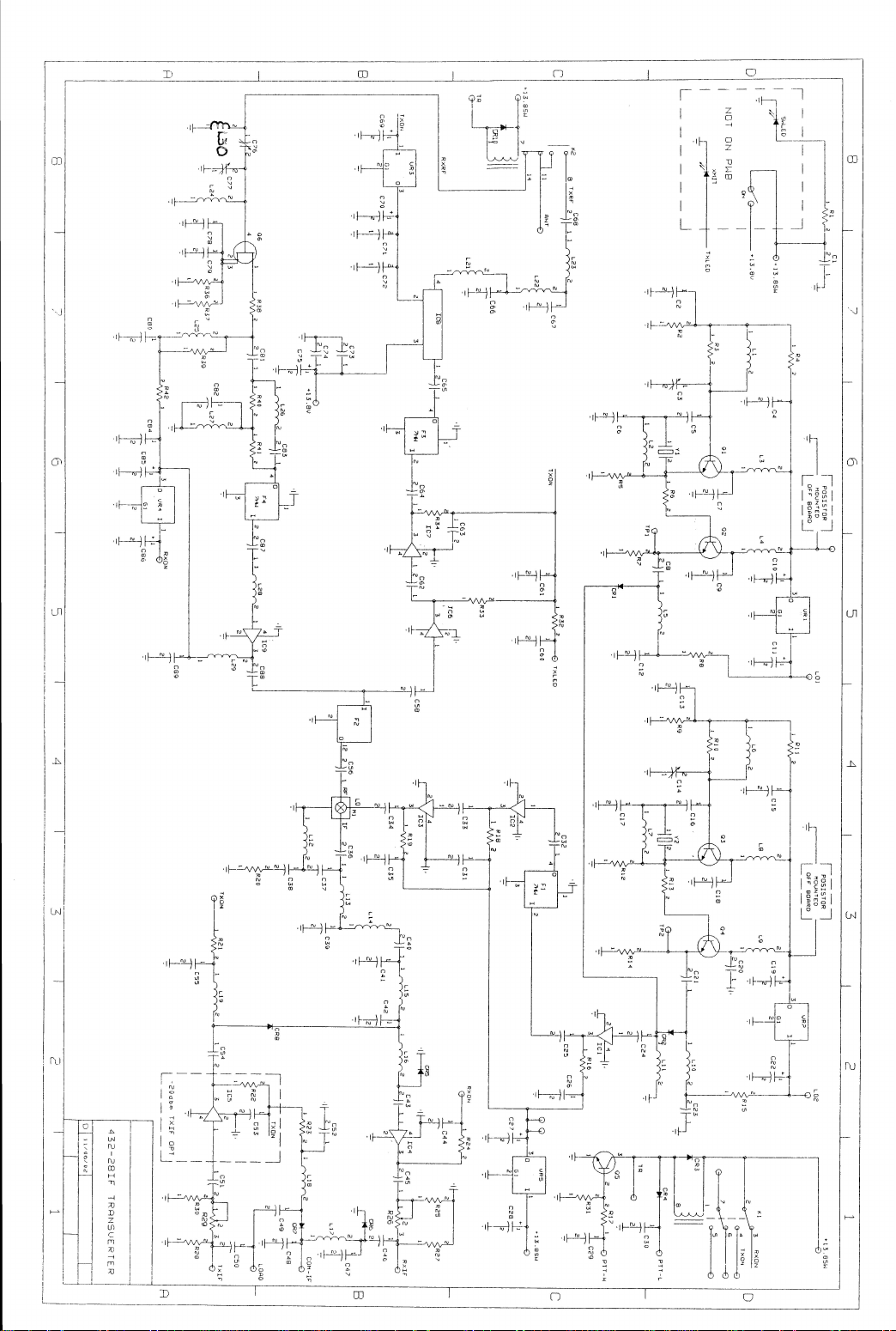
General Instructions:
Before starting assembly, read the complete document. Then inventory the components and
review the component placements and schematic. All of this “prep work” is the best way to
determine what tools will be required and to properly identify the components used. It will help to
understand important alignments of the active components or any other component such as a
relay or filter that are difficult to remove from the circuit board after installation. This is also the time
to decide which option or options you will want to install if any. Take time to review the suggested
assembly tips and practice if necessary winding coils or soldering surface mount components.
Some of the components will be the smallest size you may have ever seen! Some may be the
strangest shapes! Take time to look at them all so you are not surprised when it comes time to
install it! If you have any questions about the assembly of this kit now is the time to consult us at
Down East Microwave. If you are ready, get started and have fun!
/Kits/432-28k_RevE.doc 1 Rev. E 12/27/2007

General Assembly Tips
Soldering surface mounted active components (transistors etc.):
• The DOTS on the MMICs (IC1 - IC7) determine their orientation (See Figure 1A) and must
be observed and positioned correctly prior to soldering. IC 9 is configured by its tab. The
PHEMT (Q6) orientation is determined by it’s lead formation (See Figure 1B) which
corresponds to the assembly diagram. Leads on all active surface mounted components
should be somewhat flat against the mounting surface, if they are not, a tool such as a small
bladed screw driver can be used to flatten them.
• Align the component in place based on the diagram.
• While holding the component in place, solder one lead to hold the component in place and
observe the alignment of all leads.
• If the alignment is acceptable, solder the remaining leads. You need enough solder to cover
the lead and mounting surface for the entire lead length. Additional amounts results in a
smaller solder roll! (See Figure 2 shaded areas)
Input Lead is
angle cut
S D
FPD750
03
G
Figure 1A Figure 1B
Leads flat to trace, 4 places
Some spring back is OK
Solder shown in shaded areas
Solder full length of lead, 4 places
PCB Trace
S
Typical side view of four leaded surface mounted device, lead bending close to body
Figure 2
Soldering surface mounted passive components (chip resistors, capacitors and inductors):
• Determine the component mounting position based on the assembly diagram.
• Without the component in place, heat one side of the mounting area and flow a small
amount of solder on it. (Tin the pad)
• Place the component in the correct position per the assembly diagram, it should now have
one end over the previously melted solder.
• Holding the component in place with tweezers or other soldering aid, heat the pad with the
previously melted solder and allow the component to flow into the solder. Remove the heat
and when the solder has solidified, remove holding tool.
• Now heat and flow solder to the other side of the component and your done!
/Kits/432-28k_RevE.doc 2 Rev. E 12/27/2007

Soldering leaded components (resistors, capacitors, diodes, etc.):
Depending on your available tools, you can solder your transverter’s components from either
the top or bottom of the PCB. It is suggested for the home assembler to use a method that is
comfortable. A simple holding vise can be utilized to allow the components to be ‘dropped in’
from the topside and soldered on this side without flipping over the assembly. As an alternate
method, you can insert one component at a time in the correct mounting location and gently
push down to the circuit board, while holding the component, flip over the circuit board and
bend the leads over in opposite direction to hold the component in place. Although this is the
most reliable method, there are some drawbacks if the component must be removed when the
PCB is installed in the enclosure.
Rework of soldered components if needed:
The easiest method to rework soldered components is to employ a de-soldering braid that is
specifically designed for this purpose. It can be purchased at any electronics store. Place the desoldering braid on the lead that you are removing and apply heat to it. Without excessive pressure,
the solder will melt and flow into the braid leaving the lead or component ready to be removed. The
DEM 432-28K or CK is easy and fun to assemble even for the first time kit builder and can be
completed in any order that is comfortable, however DEM Inc. suggests the following assembly
procedure to minimize errors and possible frustration.
Printed Circuit Assembly Notes:
Your kit is provided with easy to read component placement diagrams that show the
component placement and the reference designators that correspond to the provided component
list (Bag 1 - Bag 4). Each side of the printed circuit board (PCB) is also shown to eliminate mirror
image assembly errors. The Top and Bottom side assembly operation should always begin by
aligning the PCB outline with the out line of the component placement diagrams. Use the notches
on the longer sides of the PCB board as a key. You may also use the printed lettering on the
topside of the PCB board for an indicator. You will also notice on the assembly diagram that there
are circles, double circles, and “X” shown. These are shown to provide locating help when
installing components. Components are mounted in the single holes. Double Circles are
Mounting Holes and Holes with “X” are for Wire installation only!
Surface Mount Component Suggested Assembly:
Referring to the PCB assembly diagrams, you will see that there are five (5) surface mounted
MMIC’s on the bottom side and three (3) MMIC’s and a FET on the Top side. All four of the Top
side active components may be installed as options depending on whether your application
requires them or not. The details of these options start on page 13.
The assembly operation should begin by orienting the PCB with the topside assembly diagram.
Orientation can be determined by observing the notches on the long sides of the PCB. Observed
polarity using either the DOTS or lead configuration as explained in the Assembly Tips section.
Surface Mount Component Suggested Assembly:
1. On the TOP side, depending on your requirements, install and solder Q6 and IC9. They
both have very specific orientations. Q6 has only one wide lead.
2. On the bottom side, install and solder the balance of the bottom side active components IC1
- IC3, IC6-IC7.
3. Recheck orientation of all active devices installed with component placement diagram.
/Kits/432-28k_RevE.doc 3 Rev. E 12/27/2007

General Assembly:
Start by installing all surface mount resistors, capacitors and inductors. Install as shown on
the topside component placement. Most of them are located by Q6 and IC9. Follow the surface
mounted passive component assembly tips presented earlier in this document if required.
L1, L6, L21, L22 and L23 must be formed prior to installation. The coils should be wound
around the supplied 1/8” wooden mandrel. Winding coils is not an exact science and you should
not be intimidated by it. Using the supplied specified enamel wire size, extend about ¼” in a
perpendicular direction off the mandrel and wind the wire around it, counting each evolution as
one turn. When the total number of turns is completed (BAG 3 component list) cut the wire an
additional ¼” beyond the mandrel. Form the two leads so they are pointing in the directions shown
in the forming side view details below.
~1/8"
Solder Coat
~1/8"
Solder Coat
Solder Coat
~1/8" 2 places
L21, L22 & L23 L1 & L6
Dress the turns together if they are out of shape from winding, remove the coil from the drill bit.
The coil forming is complete! To ensure a positive solder connection, the 1/8” leads should have
the enamel insulation removed prior to soldering. This can be accomplished by applying solder to
a hot soldering iron tip and placing the lead in the molten solder, you will see the insulation bubble
indicating that it has melted (The tinned lead should be a silver color indicating that the insulation
has been removed and the solder has tinned the base metal, if not repeat the process). As an
alternative, the enamel can be removed by scraping the 1/8” leads with a razor blade until the base
metal is exposed. Solder coat the exposed base metal, do not allow the outside diameter to
increase so that the coil will not fit in the mounting hole. Install and solder all prepped inductors as
shown on the component placement diagram, surface mount or through hole.
Now assemble and solder the components in the following suggested order as shown on
the component placement diagram.
STEP OPERATION and NOTES
1
2 Form, install and solder L2 - L5, L7 - L16, L19 molded Chokes
3 Install and solder C3 ,C14, C76, and C77.
4 Form, install, and solder all leaded resistors
5
6
7 Install M1. Align all pins and be careful of the solder flow.
8 Install Filters F1 - F4. Do not bend over the case tabs. Solder all leads on the bottom side
9 Install Relays K1, K2
10 Install Y1 and if 2nd oscillator option is required. Install Y2.
11 Install VR2- VR5
Form, install and solder CR1 - CR5, CR8 and CR10 (7 total) Note: Ensure proper polarity
Form, install, and solder all leaded capacitors. Note: Ensure proper polarity on all Electrolytic
capacitors as shown on the assembly document.
Install and solder Q1 - Q5, Note: Ensure proper polarity by following component placement
Install and solder wires in the shown areas on the component placement diagram (holes with an
“X”) per the table below. Do not lay wires directly on the board or route underneath the PCB!
Even though this makes for a neater assembly, doing either will cause undesired oscillations and
spurious responses.
/Kits/432-28k_RevE.doc 4 Rev. E 12/27/2007

Strip ≈ ¼” from each end and solder tin the end prior to installing the wires. NOTE: Flying leads
are wires that will be connected later in the assembly process.
WIRE FROM TO SIZE in
Inches
#26 Teflon TXON near R21 TXON near C69 6”
#26 Teflon +13.8 SW bus near R1 Flying Lead (for Power Switch) 2”
#26 Teflon +13.8 SW bus near R1 Flying Lead (for LO switch) 4”
#26 Teflon +13.8 SW near CR3 +13.8 SW near K2 3 “
#26 Teflon +13.8 SW bus near R1 +13.8 SW middle of K1 3½”
#26 Teflon +13.8 SW bus near R1 +13.8 SW near C28 3½”
#26 Teflon TXLED Flying lead 2”
#26 Teflon LO1 Flying lead 2”
#26 Teflon LO2 Flying lead 3”
#22 Teflon RXIF Flying Lead 1¼”
#22 Teflon TXIF Flying Lead 1¼”
#26 Teflon RXON near R24 RXON near VR4 3½”
#26 Teflon TR near Q5 TR near K2 3”
#26 Teflon +13.8V near C75 Flying Lead 4 1/2”
#18 Teflon +13.8V Solder to pad near C75. Flying Lead 4 “
Select either a PTT- High (+1 to +15 VDC) transmit keying or a PTT - Low (Push To Talk to
ground) keying function for the transverter. This input is required for keying the transverter and will
depend on your transceiver. Consult your transceiver’s manual for details if you are not sure.
Install and solder a 4” #26 Teflon wire in the desired connection and leave it as a flying lead. If you
plan to use an external amplifier or preamp that requires a transmit key line, the extra set of
contacts in relay K1 may be utilized. The contacts are marked C (Common) NO (normally open)
and NC (normally closed) and are referenced to Receive. You may connect the C to either
ground, (any via hole) or a voltage (+13.8SW) if required. Use the supplied #26 Teflon wire. Then
depending on your requirements, either the NO or NC may be connected to the AUX jack on the
back wall of the transverter after the PCB is installed.
Post soldering:
All leads including wires extending through to the bottom side of the PCB should be trimmed as
short as possible to eliminate possible shorting to the enclosure when installed. Check your work
for solder bridging to adjacent traces, incorrectly installed components, and missing components.
Now refer to the bottom side component placement diagram and review the positioning of
the brass angle. Position it as shown and solder it to the ground plane. It is suggested to re-flow
the solder under the F2 and F4 filter. This may be a high spot on the board and it is important to
not have any gaps between the brass angle and the ground plane but also have the brass as flush
to the ground plane as possible. The printed circuit is now ready for testing.
PCB assembly into the enclosure:
The enclosure is machined at the factory for your convenience. Notice that the enclosure
and the PCB have corresponding holes, which are directional and must be aligned correctly. The
PCB installation in the enclosure is easy if the suggested assembly steps are followed.
If not already done, remove the cover from the enclosure and wipe the inside clean to remove any
remaining metal particles that may have been trapped during machining. Install the 4-40 x 3/8”
mounting screws that correspond with the PCB in the enclosure. There are twelve total. Install the
screws through the outside of the enclosure and attach a 4-40 nut to them on the inside of the
enclosure. Make the nuts snug but do not tighten. Then trial fit the PCB. If one or more screws do
/Kits/432-28k_RevE.doc 5 Rev. E 12/27/2007

not line up with the PCB, loosen the nut slightly, and re-position the screw, then fit the PCB again.
AUX
A
A
When all mounting screws are aligned, tighten the nuts.
Now install all of the connectors in the enclosure. Using Figure 3A and 3B, install the type
“N” connectors as shown. Cut the center pins to 1/8” in length. The coaxial cable will be installed
on the connector after it is attached to the PCB. Now install the remaining rear wall mounted
connectors, per the location in Figure 4.
Prepare the solder lug as shown prior to installing
NUT
Top View of Solder Lug,
Bend at Dotted Line
Side View of formed
Solder Lug
Figure 3A
Solder coax center conductor
to connector pin
Solder coax shield
to formed lug
Connector
Solder lug
RG/188 coax from
PWB "ANT"
PCB MOUNTNG AREA
Figure 3B Inside View of Enclosure, Solder Lug Installation on the ‘N’ or UHF Connector
IIF
TX RX PTT L - H
NTENNA
XMIT RECEIVE 13.8 VDC
NTENNA
Figure 4 Connector Mounting Positions, Outside View
2 - BNC connectors at the RXIF and TXIF positions using the supplied 3/8” nuts. If washers
are supplied, install them on the inside of the enclosure. Do not install solder lugs. If you
have difficulty tightening the connector, connect an adapter or cable connector and hold this
while tightening to keep it from spinning.
3 - RCA connectors for AUX, PTT-H-L and 13.8 VDC using the supplied hardware. The flat
washer should be installed under the solder lug on the inside of the enclosure. After
tightening, the lug should be bent away from the wall.
/Kits/432-28k_RevE.doc 6 Rev. E 12/27/2007

PCB assembly into the enclosure, continued.
Place the circuit board over the mounting screws and place two nuts on opposite corners on the
screws extending through the PCB and tighten evenly. Now install VR1 by first trial fitting it into
position. Cut the leads to fit using a 4-40 x3/8 screw in the enclosure mounting hole as a depth
guide. Bend the leads slightly so that the body of VR1 will fit flush on the enclosure. Place a nut on
the 4-40 screw and tighten. Then tack solder one or two leads of VR1. Remove the PCB from the
enclosure and solder VR1 correctly and trim the excess leads. Now re-install the circuit board as
before with VR1 attached to the enclosure.
1 - Mount the POWER switch using the supplied hardware. Mounting of the switch should be so it
is toggled per Figure 5.
2 -Mount the LO2-432 switch using the supplied hardware. Mounting of the switch should be so it
is toggled per Figure 5.
At this point, some of the flying wires will need to be connected in the enclosure to allow
preliminary electrical testing. Refer to Figures 4 and 5 for correct connectors.
Connect the #26 Teflon (PTT-L or PTT-H) wire to the wall mounted RCA jack, then connect a
1000pF capacitor (labeled “102”) to the center pin and solder lug and solder (See Figure 4).
Connect and solder the #26 Teflon wire from LO2 on the PCB to the lower terminal on the LO
switch. This terminal will be closest to the printed circuit board.
Connect and solder the longest #26 Teflon wire from the +13.8SW bus near R1 to the middle
terminal on the LO switch.
Connect and solder the #26 Teflon wire from LO1 on the PCB to the terminal closest to the
opening on the wall mounted LO switch.
Connect and solder the #26 Teflon wire from the +13.8V on the PCB (near C75) to the middle
terminal on the wall mounted POWER switch and solder.
Connect and solder the last #26 Teflon wire from the +13.8SW bus (near R1) to the terminal on the
wall mounted POWER switch that is closest to the opening in the enclosure.
Connect the #18 Teflon wire from the 13.8V connection and solder it to the center of the wall
mounted DC power jack (13.8 VDC). Then Connect and solder the 100µF capacitor to the DC
power jack, observed polarity, positive lead to the center pin of the jack, negative to the ground
terminal.
432
LO 2
Switch Toggle Direction
POWER ON XMIT
Figure 5 Switch / LED Mounting Positions
/Kits/432-28k_RevE.doc 7 Rev. E 12/27/2007

Electrical Test Verification of PCB. Receive only: Apply 13.8 volt, current limited supply (0.5
amps) to the RCA DC Power jack. The center pin is positive. Turn on the power switch. The
transverter will now be in the receive mode. Check the voltages in the order shown, on the test
table then continue by checking the oscillator section. Voltages are referenced to ground, which is
the enclosure. Use the component placement diagram for test point location.
TEST Test Point Location VOLTAGE
RX1 +13.8SW Power supply Voltage
RX2 Junction of C84 & R42
RX3 Junction of R42 & R39 3.5 - 4.5 VDC v
RX4 Junction of IC9 & L29
RX5 Junction of R19 & C34
RX6 Lead of C33 closest to R19
RX7 Junction of R18 and C33
RX8 Lead of C32, closest to R18
RX9 Junction of R16 and C25 2.0 - 7.5 VDC
RX10 Leg of C24, closest to VR5
RX11 Verify LO1 and LO2 correspond to Switch Power supply voltage
RX12 Junction of R24 and IC4 (if installed)
RX13 Junction of C43 and IC4 (if installed)
5.0 ± 0.5VDC
5.0 ± .5VDC
5.0 ± 1VDC
1.5 ± .5VDC
5.0 ±1VDC
2.5 ±. 5VDC
1.5 ± 1.0VDC
5.0 ± 1VDC
1.8 ±. 5VDC
Due to variances in GaAs FET devices, voltages will vary. Optimal performance occurs between
37 - 43 mA as measured across R42. I in mA =E (voltage drop across R42)
÷ the value in Ohms of
R42. The current may be adjusted by changing the value of source resistance. Higher source
resistance, lower drain current. There is no need to adjust the values if it is in tolerance.
RX Test Trouble shooting
Failed
TEST
RX1 +13.8SW shorted to Ground, Power supply in current limit, Missing wire.
RX2 Output on VR4 shorted to ground, Q6 or IC9 installed incorrectly.
RX3 If voltage is 5.0V, Q6 is damaged, not installed correctly or R38 is open. If it is < 3.o volts, Q6
not installed correctly or damaged
RX4 Check L29. Open or shorted to ground. IC6 shorted to ground, defective, or installed incorrectly.
RX5 Missing +13.8SW wire to VR5. R19 wrong value or shorted. IC3 shorted to ground, defective, or
installed incorrectly.
RX6 If >2.5 VDC, and RX5 test passes, replace IC3. If < 1.0 VDC, C33 is shorted or the input of IC3
is shorted to ground.
RX7 R18 wrong value or shorted. IC2 shorted to ground, defective, or installed incorrectly.
RX8 If >3.0 VDC, and RX7 test passes, replace IC3. If <2.0 VDC, C32 is shorted or the input of IC2
is shorted to ground
RX9 R16 wrong value or shorted. IC1 shorted to ground, defective, or installed incorrectly.
RX10 If >2.5 VDC, and RX9 test passes, replace IC3. If < 1.0 VDC, C24 is shorted or the input of IC1
is shorted to ground.
RX11 Switch wired wrong. If low voltage, wire, capacitor or regulator shorted to ground on the LO
input on PCB.
RX12 R24 wrong value or shorted. IC4 shorted to ground, defective, or installed incorrectly.
RX13 If >2.5 VDC, and RX12 test passes, replace IC4. If < 1.0 VDC, C43 is shorted or the input of IC4
is shorted to ground.
Probable causes
/Kits/432-28k_RevE.doc 8 Rev. E 12/27/2007

If any of the RX tests fail, repair or consult Down East Microwave before proceeding with the
oscillator testing.
Local Oscillator 1 (432) Testing:
Verify that there is a 101.000 MHz. crystal in the Y1 position. If there is only one crystal installed, it
should be in the LO1 oscillator position. This test will not work if a crystal is not installed. Switch
the LO switch to the 432 position. Probe TP1 with the positive lead of a Voltmeter. Adjust C3 for
maximum voltage, note where the capacitor is positioned. A midrange position is preferred. If the
capacitor is at the maximum (bottomed out clockwise), spread coil L1, 1 to 2 turns and readjust C3
so it comes off of the bottom. If the capacitor is at minimum position (top maximum counter clockwise), compress coil L1 and if necessary, you may need to wind a new coil with an extra turn and
replace it. The final voltage at TP1 should be approximately 1.0 - 1.5 volts. If a frequency counter
is available probe TP1 and adjust C3 for 101.00000MHz. If your frequency counter is capable of
measuring up to 500Mhz., you can probe the junction of C34 and M1 to verify that four (4) times
the fundamental frequency of the crystal (404.00000 MHz.) is present. If the specified voltage at
TP1 cannot be obtained please start the Local Oscillator trouble shooting section on the next page.
If the frequency cannot be obtained, skip to step #8 of the Local Oscillator trouble section. If the LO
1 is working correctly, skip to the TX testing section. If you have the install the 2
nd
Xtal, repeat the
above steps noting that you now adjust C14, stretch and compress L6, and probe TP2. C14 is
different and midrange is indicated in the next figure. Your final frequency will be the frequency
marked on your 2
nd
Xtal x 4. Again, if the specified voltage at TP2 cannot be obtained please start
the Local Oscillator trouble shooting section on the next page. If the frequency cannot be
obtained, skip to step #8 of the Local Oscillator trouble section.
Midrange
Solder Joint
Maximum
Minimum
C14 Capacitance Position
Local Oscillator Trouble Shooting Section:
All circuit values used in this trouble shooting section assumes the LO1 is the problem. LO1 and
LO2 are the same except for the type of capacitor use for C3 and C14. If you are trouble-shooting
LO2, substitute the component designators. Also, understand that it is possible that the voltage at
TP1 may be low and the oscillator could be working perfectly. But, this should be verified.
The crystals used in this circuit are 5
th
overtone design. If L1 is distorted enough or the
components tolerances are out, you can cause the oscillator to operate on a different overtone.
Crystal failure is a very rare occurrence! If there is any voltage peek at TP1 while adjusting C3,
and L1 does not vary much from its specifications, it should be assumed that the oscillator circuit is
correct. For verification of this, perform the following tests 1 - 8. If the oscillator is on or close to
frequency, (404.00000) skip to test #8.
/Kits/432-28k_RevE.doc 9 Rev. E 12/27/2007

1.
Verify voltage at the junction of L5 and CR1. This should be 0.7VDC ± 0.3 VDC. If it is high,
CR1 is missing, installed backwards, damaged, or L11 is missing or open. If it is 0VDC, check for
a short in the circuit after R8. Use schematic and component placement diagram. If you find an
error in assembly, correct it and restart the oscillator test.
2. If the voltage is correct at the junction of L5 and CR1, probe the junction of R16 and C25 with a
voltmeter while adjusting C3. The voltage should vary. Adjust C3 for a
minimum
voltage at this
point. If less than 4 volts can be achieved, the multiplier section of the oscillator is working
correctly. If the voltage stays high (6 - 7 volts) and doesn’t vary downward during the adjustment,
the problem is in the main oscillator circuit.
3. With the voltmeter, probe the junction of R6 and Q2. This voltage should vary when C3 is
adjusted. If it does not vary, then the problem is in the Q1 circuitry. If it does vary and there is no
change of voltage on TP1, then the problem is either a defective Q2 or its bias circuitry. Verify the
suspected transistor by following step 4.
4. To verify the bias voltages of transistors Q1 and Q2, you need to measure these voltages at the
transistors leads. Remove the PCB from the enclosure and keep the +12 volts connected. Be sure
that there is a ground connection between the enclosure and the PCB. Examine the schematic
and component placement diagram for exposed leads of other components that are connected to
the desired test points. Start by verifying the output of the 9 Volt regulator, VR 1. Then check Q1.
Collector = 9 volts. Base =1.5 - 2.5 volts. Emitter =1.3 -2.2 volts. For Q2, collector = 9 volts.
Base = 1.3 - 2.2 volts. The Emitter is TP1.
5. If these voltages do not check out correctly, you need to make the determination if the bias
resistors, chokes and L1 are installed correctly. They may also have a solder bridge on the bottom
side of the PCB. All of the resistors should check out with a ohm meter except R2 which is
shorted with L1. Also, verify the placement of Q1 and Q2. If the transistors are installed
incorrectly, or a solder bridge caused a wrong bias voltage (higher than specified) assume that the
transistor is destroyed. You may still try it after repair, but it is unlikely!
6. If the voltages check out OK, verify that C6, C5 and C2 are installed correctly and do not have
any solder shorts. Measure with an ohmmeter.
7. If they check out OK, its time for the final test. Remove the Y1 crystal and L2 inductor. Be
careful with L2. It is brittle! Now install a 51-ohm (36 - 75 ohm will work) resistor in the Y1
position. Apply power to the circuit and probe TP1. If you can obtain a voltage swing by varying
C3, then verify what frequency it is operating on with a frequency meter or a FM broadcast radio.
You should be able to adjust C3 for 101 MHz. If not, stretch and /or compress L1. If you cannot
obtain any oscillation or if the frequency cannot be obtained with the specified L1 size, then the
oscillator circuit is assembled wrong or Q1 is defective. If you can adjust the frequency, set L1
(stretch and/or compress) so that C3 is in the mid position. Leaving everything adjusted correctly,
power down the circuit and remove the resistor in the Y1 position and re-install Y1 and L2. Power
the circuit up. If it doesn’t oscillate, you have a defective crystal or open L2.
8. If the oscillator is operating but the frequency cannot be netted, verify that C3 is in mid position.
If not re-adjust L1 to do so. If the oscillator shuts down when the frequency gets close, and C3 is
in mid position, allow the oscillator to run at any frequency for 24 hr. before attempting readjustment again. You may continue the testing and assembly of your transverter. Just don’t do
the final assembly. If after re-adjustment, and you are sure of your frequency calibration (do not
use a FM radio or HT for calibration!!!) and the L1 and C3 circuitry adjustment is correct, return the
crystal for replacement.
After the oscillator is performing to specification, re-install the PCB in the enclosure and continue
with the Transmit Electrical Test.
/Kits/432-28k_RevE.doc 10 Rev. E 12/27/2007

Transmit Electrical Test:
The voltage checks listed are for the transverter in the TX mode with any oscillator enabled.
After verifying that the DC power is connected to the transverter and the power switch is in the on
position, place the transverter in the Transmit mode. This is done by keying the PTT-L or PTT-H
circuit. Either ground or the +13.8V supply will work. This will also depend on how you have
configured your transverter. As you enable the TX mode, a “click” may be heard from the relays
on the PCB. All voltages are referenced to ground (the enclosure).
TEST Test Point Location Correct Test Results
TX1 TR connection near Relay K1
TX2 ANT connection near K2 and K2 side of C68 Measure short with Ohm meter
TX3 TXON connections - All Positions Power supply voltage
TX4 RXON connections - All positions 0 VDC
TX5 TXLED connection Power supply voltage
TX6 Junction of C70 - C72
TX7 Junction of R34 and C64
TX8 Leg of C62 closest to R34
TX9 Junction of R33 and C62
TX10 Leg of C58 closest to R33
TX11 Junction of L16 and CR5
TX12 Junction of R22 and IC5 (if installed)
TX13 Junction of C51 and IC7 (if installed)
0.7 VDC ±0.5VDC
5.0± 0.5VDC
5.0 ± 1VDC
2.0 ± .5VDC
3.5 ± .5VDC
2.5± 0.5VDC
0.8 ± .3VDC
3.5 ± 1VDC
1.5 ± 0.5VDC
TX Test Trouble shooting:
Failed
TEST
TX1 Missing +13.8SW or TR jumper wires. Missing or defective Q7, R29, or CR8
TX2 Defective K2 or not soldered correctly
TX3 Defective K1, shorted TXON voltage to ground, If defective all other tests will fail.
TX4 Defective K1 or PTT circuit not working correctly
TX5 R32 missing or shorted
TX6 VR3 Missing or shorted to ground. C70 installed backwards
TX7 If low, IC7, R34 installed incorrectly or shorted. If high IC7 defective of installed incorrectly
TX8 If low, IC7 shorted. If high, defective IC7
TX9 If low, IC6 , R33 installed incorrectly or shorted. If high, IC6 defective or installed incorrectly
TX10 If low, IC6 shorted. If high, defective IC6
TX11 If low, R21missing,CR8 or CR5 shorted. If High, CR8, CR5 is backwards, damaged or missing.
TX12 If high, IC5 defective. If low, missing jumper wire, defective IC5, solder short, wrong value R33
TX13 If low defective IC5 or installed incorrectly. If high IC5 defective
Probable causes
**If any of the Transmit tests fail, repair or consult Down East Microwave before proceeding
with the Kit!!!**
If all of the tests pass, you may mount the PTC-50 Thermistor next. The Thermistor is used
for frequency stability and does not need to be installed at this time but it is convenient. If you are
unsure of the Xtal’s performance or question the oscillators performance, it may be installed later.
If so, install the rest of the 4-40 nuts on the top side of the PCB and repeat a few of the electrical
tests to verify that nothing was shorted on the PCB after assembly. Then proceed to the power
module installation section. If you wish to install the PTC-50 now, continue to the next page.
/Kits/432-28k_RevE.doc 11 Rev. E 12/27/2007

PTC-50 Thermistor installation
The installation of the PTC-50 Thermistor may be done at any time but it is most convenient
to do it before the final wiring is completed. Because it is important to determine if the oscillator
circuit is 100% functional before installing the Thermistor, some double work is required. We, at the
Down East Microwave factory, install the Thermistor after complete assembly and the oscillator
has aged for 24 hours (a burn in period). You may do the same but it is not required. Just expect
to see some frequency drift for the first 24 hours of operation.
To install the Thermistor correctly, remove the PCB from the enclosure. To do this, unsolder the PTT wire, and the 3”, #18 wire from their RCA jacks. Then remove both the LO and the
Power switches from the enclosure. Next remove the 2, 4-40 nuts and the VR1 mounting screw.
The PCB should come out of the enclosure.
Locate the Thermistor and remove one of the attached wires with some heat from a solder
iron. Then review the diagram below. Note that the Thermistor is attached by solder to the crystal.
Start by tinning the case of the crystal. Heat the case with an iron and flow some solder on it.
Then while still heating the case, place the side of the Thermistor without the wire, in the molten
pool of solder and remove the iron. Now before the crystal / Thermistor assembly cools, note
where the crystal and Q1 almost touch. Heat the case of Q1 with your iron and flow a bead of
solder so that it attaches to the crystal. Allow it to cool and then inspect for a good solid
connection. If in doubt, re-flow and add more solder. Now attach the lead of the Thermistor to the
via hole by VR1. This via is the output of the VR1, which is 9VDC. If the second local oscillator is
used, a Thermistor may be installed to that crystal if desired but is not included in the kit. It would
also be recommended to exchange VR2 for a higher wattage regulator unless it is tied to 13.8VDC.
IF the second oscillator is used for satellite operation, the frequency stability may not be that
important because of the Doppler shift. You may now re-install the PC board in the enclosure and
continue the assembly on the next page.
Some important notes about the PTC-50, Crystal heater installation. The crystal needs to be
attached to the Q1 or Q3 transistor for two reasons. One is to provide a DC path for the Thermistor
through the case ground of the transistor. The other is to maintain a constant temperature of the
oscillator transistor. We have found that this is best for frequency stability. The theory is that the
internal air temperature of enclosure will be less than the crystal and oscillator transistor with the
Thermistor attached. If that is always the case, the temperature remains constant on the most
temperature sensitive components.
If the solder bead is not attached to the transistor, the Thermistor will not heat up unless a
wire is attached from the crystal case to ground. This is not as effective as the total attachment.
Proper Attachment of Thermistor to Crystal
/Kits/432-28k_RevE.doc 12 Rev. E 12/27/2007

Power Module Installation:
Place the power module (IC8) on the enclosure floor in its mounting location and trim the
leads so they do not extend past the mounting pads. They should be approximately 3/8” long
once trimmed. Now find the tin plate shield and trial fit it over the power module. You will need
to trim some of the openings in the shield to clear the power module leads. Wipe the mounting
surfaces of the enclosure floor and flange of IC8 to verify the surfaces are free any foreign
matter and deep scratches before applying a thin even coating of thermal compound to the
mounting flange. Then place IC8 on the enclosure floor while lining up the leads with the traces
of the circuit board. Install two 6-32 x 3/8” screws through the outside of the enclosure up
through the mounting flange of the module and through the shield mounting holes. Install two 632 nuts and verify that the leads of the module do not touch the shield. Then position the
module and shield so that the shield touches the PCB and tighten the 6-32 screws. Solder the
module’s leads o the traces then tack solder any part of the shield to the ground plane of the
PCB. Make as many connections as possible. This shield provides the lowest possible
inductive path between the PCB and the module. This is important for stability.
LED Installation:
Note: The longer lead on the LED is positive.
• Prepare the “XMIT” LED by supporting the SHORT lead (negative) at the LED body, bend
the lead 90º away from the longer lead.
• Place the “XMIT”LED in the wall mounting hole (see Figure 5) and place the previously
formed lead on the ground plane circuit close to the edge of board and solder.
• Cut the positive lead of the “XMIT” LED to approximately 3/8”. Form a “J” in the lead by
bending with pliers.
• Connect the #26 Teflon wire from the hole in the PCB near labeled TXLED, to the “J”
formed positive lead on the “XMIT” LED.
• Place the positive lead of the “ON” LED in the hole by R1 labeled ON LED.
• Form the “ON” LED so that the body fits into the hole in the enclosure.
• Tack solder the ground side of the “On” LED to the ground plane
Final PCB assembly into the enclosure
• Connect the #18 Blue Teflon wire from the wall mounted DC power jack (13.8VDC) and
solder., Connect and solder the 100µF capacitor to the DC power jack, observed polarity,
positive lead to the center pin of the jack, negative to the ring ground terminal.
• Connect the #22 Teflon wire from the stand alone hole in the PCB labeled RXIF to the BNC
RX jack and solder.
• Connect the #22 Teflon wire from the stand alone hole in the PCB labeled TXIF to the BNC
TX jack and solder.
DEM 432 - 28 User Options:
The following final assembly instructions cover all of the options that are available for this
kit. This list of suggestions will help you decide which options you will want to install.
Common Antenna for both transmit and receive. If you plan to connect an antenna directly to
the transverter or use a solid-state amplifier with antenna switching built in, do this assembly.
Add an external preamplifier and bypass the internal GaAs-FET. If you plan to use an external
or mast mounted preamplifier, this option is suggested. Any additional gain in front of the stock
transverter will degrade the IMD performance, and reduce the dynamic range of the transverter by
the amount of additional gain.
/Kits/432-28k_RevE.doc 13 Rev. E 12/27/2007
Common IF option. If you use and transceiver with a single transverter port or a transceiver with
A
a power level up to 10 watts.
Split RX / TX Ports for high power amplifier use. If you plan to use a tube type amplifier with
external preamplifier and sequenced switching schemes, such as an EME station, assemble this
option.
Auxiliary switching contacts. Used for external switching circuits or to hard key a solid state
amplifier.
Install the TXIF or RXIF gain stages. Only if the TX drive is low from the transceiver. Only if RX
IF gain is desired.
Common Antenna for both transmit and receive:
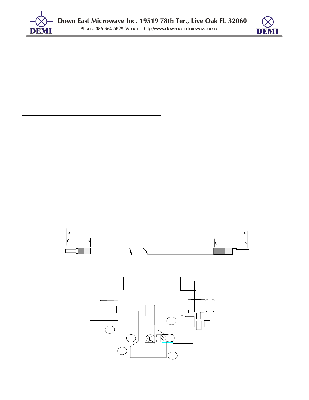
Prepare the common output coaxial cable as follows: (See Figure 6)
Cut the coax 2” - 2 1/32” long.
Remove the outer insulation ½” from one end and ¼” from the other.
Remove the braided shield ¼” from the ½” stripped side.
Remove the braided shield 1/8” from the other side.
Remove the center conductor insulation from each end allowing an extension out of the
remaining shield. Cut the center conductor wire to ~1/16” to prevent shorting.
Solder tin the center conductor on both ends and solder tin the shield on the ½” end.
Bend the center conductor on the longer stripped end 90º
Position the ½” stripped end on the circuit board by placing the center conductor in the hole on
the board labeled “ANT”. This hole is located near relay labeled K2. See figure 7.
Solder the shield to the ground area adjacent to the “ANT” hole for the center conductor, then
solder the center conductor in the “ANT” hole.
Route the coaxial cable around the relay to the solder lug on the wall mounted ‘N’ connector
Solder the shield to the solder lug, then solder the center conductor to the ‘N’ connector center
pin as in figure 3A.
~2.0 - 2 1/32"
1/4"
<=Shield
"AN T " E N D = >
1/2"
Figure 6 Cable shown broken for clarity
K2
RG/188 COAX
CABLE
COMMON “N”
NT
Figure 7 Coaxial Cable mounting on PCB shaded areas are solder points
/Kits/432-28k_RevE.doc 14 Rev. E 12/27/2007

Add an external preamplifier and bypass the internal GaAs-FET
On the following page is block diagram of the receive converter. It shows the standard and an
option of using an external preamplifier. It is recommended that if you use an external or mast
mount preamplifier, you should bypass the internal one. The transverter may be configured this
way at any time.
1. If you do not wish to have the receive signal routed through the T/R relay in the transverter,
refer to the component placement diagram and remove R38, L25, and R39. The pad that is the
junction of C81, L25 and R39 is the new RX input. The RX signal will pass through the diplexer
and then into the F4 filter.
2. If you wish to still use the T/R relay in the transverter, remove R35 and C76 from the PCB after
performing the modification in step 1. Then run a jumper coax from the R35 pad to the new RX
input.
Common IF option:
A common IF option is available for this transverter. If interested, it can be supplied as a kit.
Please consult Down East Microwave Inc. for details. Options with up to 10 watts input power are
available. It is easily installed at any time and comes complete with a new component placement
diagram.
Split RX / TX Ports for high power amplifier use:
1. Remove chip capacitor C68 from original position and place were shown on the diagram.
2. Prepare a 2” piece of RG/188 coax or similar and attach it to the new C68 placement as shown.
3. Attach the other end of the coax to the spare type “N” connector.
The RX input can be left assembled the way it is. This will provide additional receiver
isolation during transmit. The K2 relay will function normally and will open the circuit to the RX
input. This will not protect an external preamplifier. IF you decide to remove the K2 relay from the
circuit, remove and replace C76 and R35 as shown in diagram below then remove the coax from
the ANT connection on the PCB and attach it to the new position shown.
/Kits/432-28k_RevE.doc 15 Rev. E 12/27/2007

X
A
RX
RG /1 88 CO A
TX
RG/188 COAX
CABLE
L19
C 68
R35
K2
C76
CABLE
NT
Split Transmit and Receive diagram
Auxiliary Switching contacts:
The auxiliary contacts in K1 are labeled C (common) NO (normally open) and NC (normally
closed). The C connection can be wired to ground or +13.8 VDC. This will then be connected or
dis-connected depending on the transverter is in transmit or receive. The contacts are marked for
the receive mode. The NO or NC can be wired to the AUX connector on the enclosure.
Install the TXIF or RXIF gain stages:
You may require additional gain on either the TXIF or RXIF and want to install either IC4 or
IC5. If your transceiver has less than 1 mW output on its transverter port, installing IC5 will enable
the transverter to produce full output power. All of the associated bias components are installed
and tested. Refer to the component placement diagram and locate IC5. Then remove the ribs as
shown below. Cut them with a razor knife and heat with a solder iron. They will jump off the
board! Then form the leads of the IC5 so that it lays flat on the circuit board. Solder it into place
as shown on the comp placement.
The same thing may be done with RXIF. Note the dot on the IC before installing. Caution!
Installing this gain stage will increase your IF gain, decrease the systems dynamic range, and will
not improve your system’s noise figure. Refer to the circuit description.
Rem ove all
R ib s P rior to
IC In s ta llatio n
IC4 & IC5 Installation
/Kits/432-28k_RevE.doc 16 Rev. E 12/27/2007

Transverter Final Tune Up:
Connect your transceiver to the transverter. Interfacing the transverter to the transceiver is easy. If
your transceiver requires a DEM TIB or AOS, follow their instructions for interfacing. If the
transverter was assembled for direct connection to your transceiver, follow the steps listed below.
1. Depending on the make and model of your transceiver, it may or may not be necessary to
enable the transverter ports. Follow whatever instructions you have in your transceiver’s
operation manual to enable transverter operation. If it requires a special connector or cable
assembly, it should be made now or contact Down East Microwave for assistance.
2. Connect all IF cables. Both receive and transmit are BNC connections on the transverter. Use
good quality coax cable to connect the 28 MHz. transverter ports from your transceiver to the
TXIF and RXIF connectors on the transverter.
3. Connect the Push to Talk line out of your transceiver to the transverter. It is labeled PTT-H or
PTT-L on the transverter and uses a RCA connector. The correct keying type should have
been configured for your transceiver during assembly.
4. Connect the 70cm antenna system or a dummy load with a power meter to the transverter. If
you chose to assemble split transmit and receive sections one of the “N” connectors is the
transmit side. Put the power meter or load there. Place a signal generator or an antenna on
the receive connector.
5. Connect the DC power to the transverter. It uses a RCA type connector. 13.8 volts is optimum
but the transverter will operate normally from 12 to 15 volts.
6. Preset the TXIF and RXIF gain controls. Turn the TXIF counter-clockwise (maximum
attenuation) and the RXIF clockwise ( minimum attenuation).
7. Power your transceiver on and leave it in the Receive mode on 28.100 MHz.
8. Apply power to the transverter and turn on the power switch. The power LED should light and
the transmit LED should not. Set the local oscillator switch to 432MHz.
9. Adjust the RXIF gain control counter-clockwise until a slight noise increase is heard in the
transceiver or just a slight movement in the “S” meter is detected. Power the transverter on
and off to verify the change in noise. The RXIF gain may be increased beyond this point, but it
will start to degrade the dynamic range of your transceiver. Find a signal on the band or use a
signal generator to determine correct frequency, or minimum detected signal level. Out of band
signals such as local repeaters will be attenuated if their output frequency is above 438 MHz or
below 430 MHz.
10. To test the transmit section, place your transceiver in the CW mode. It is recommended to test
the transverter in the CW mode because most transceivers have carrier level controls in this
mode only. If your transceiver has FM, it may be use to test the transverter if it has a power
output control. Do not use SSB or AM because it is not possible to obtain maximum output
power with a transceiver in these modes. Set the carrier/output power control to minimum or
“0” output power. Place the transceiver into transmit. Note the transmit LED on the transverter.
It should be on. While observing the power meter on the 70cm system, slowly increase the
carrier control (with key down) or power output control to maximum on the transceiver. If the
transverter is configured correctly for your transceiver, minimal power may be detected on the
70 cm power meter. Now slowly adjust the TXIF control in the transverter in a clockwise
direction while observing the power meter. Set it to obtain a maximum of 10 watts maximum. If
a power meter is not available, you may use a current meter on the DC power line to determine
if the transverter is transmitting. A maximum of 4 amps should be obtained and it should vary
as the TXIF control is varied. If 10 watts cannot be obtained with 4 amps of current drain, then
with an insulated tool, stretch or compress the L21, L22, an L23 inductors in the output low
pass filter. This will also help efficiency. After proper power is obtained, switch the transceiver
/Kits/432-28k_RevE.doc 17 Rev. E 12/27/2007

to USB and make a transmission. The power output and current drain should correlate to your
speech pattern. If a minimum of 10 watts cannot be obtained, it could be a IF drive problem.
Please consult Down East Microwave Inc.
11. You may re-adjust both RXIF and TXIF again if desired. The adjustments of the receive
preamplifier and local oscillator frequency do not need to be touched but you may if you wish.
Do not adjust any of the helical filters unless you have access to a spectrum analyzer at
minimum.
12. Put the top on the enclosure and install the screws. Your transverter system is ready to use.
Connect as you wish to use it in your 70cm system and have fun!
DEM 432-28 Component List
Resistors values are in Ohms and are ¼W unless otherwise specified. All chips are 1206.
BAG 1
R1 1K R9 470 R17 5.1K R26 1K pot R34 150 ½ W
R2 470 R10 680 R18 120 R27 220 R36 12 chip
R3 680 R11 1.5K R19 56 ½ W R28 220 R37 12 chip
R4 1.5K R12 100 R20 47 R29 1K pot R38 12 chip
R5 100 R13 47 R21 1K R30 220 R39 300 chip
R6 47 R14 100 R22 330 R31 5.1K R40 51 chip
R7 100 R15 1K R24 150 ½ W R32 470 R41 51 chip
R8 1K R16 150 R25 220 R33 330 R42 24 chip
All capacitors are disc ceramic and are pF unless otherwise specified. “E”= Electrolytic . “TH” =
Thru Hole Variable Trimmer “SMD” Surface Mount Variable Trimmer “PT” = Piston trimmer. “C” =
Surface mount Chips. “ATC” = Ceramic Chips .
BAG 2
C1 1000 (102)
C2 0.1 µF C19 2.2 µF “E” C35 0.1 µF
C3 1-8 Piston
C4 0.1 µF
C5 15
C6 39
C7 0.1 µF
C8 120 C25 120 C41 270 C65 120 C81 100 “C”
C9 0 .1 µF C26 0.1 µF
C10 2.2 µF “E” C27 2.2 µF “E”
C11 0.1 µF C28 0.1 µF C44 0 .1 µF
C12 0.1 µF C29 0.1 µF
C13 0.1 µF C30 0.1 µF
C14 1-6 “TH”
C15 0 .1 µF
C16 15 C33 120
C17 39
C18 0.1 µF
C20 0.1 µF
C21 120 C37 39
C22 0.1 µF
C23 0.1 µF
C24 120 C40 1000 C64 120 C80 100 “C”
C31 0.1 µF C53 0.1 µF C71 0.1µF “C”
C32 120 C54 1000 C72 100 “C” C88 120
C34 1000 “C” C56 100 “C”
C58 120
C36 1000 “C”
C38 18 C62 120
C39 120
C42 270 C66 6.8 “ATC” C82 12 “C”
C43 1000 C67 6.8 “ATC” C83 4 “C”
C45 1000
C51 1000
C55 0.1µF
C60 0.1 µF
C61 0.1 µF
C63 0.1 µF C79 0.1 µF “C” (1008)
C68 100 “C”
C69 0.1 µF C85 2.2µF “E”
C70 100µF “E” C86 0.1 µF
C73 100 “C”
C74 0.1 µF “C”
C75 100 µF “E”
C76 1-6 “SMD”
C77 1-6 “SMD”
C78 0.1 µF “C” (1008)
C84 0.1 µF “C”
C87 100 “C”
C89 0.1 µF “C”
/Kits/432-28k_RevE.doc 18 Rev. E 12/27/2007

DEM 432-28 Component List continued
All molded chokes have GOLD or SILVER multiplier and tolerance bands. Identify molded choke
value by the significant color band combination. “C” = 0603 chips. “HW” are tightly wound enamel
wire inductors.
BAG 3
L1 9 Turns 1/8" ID #24 “HW”
L2 0.33µH (Orange/Orange) L11 1.0µH (Brown/Black)
L3 1.0 µH (Brown/Black) L12 0.22µH (Red/Red)
L4 1.0 µH (Brown/Black) L13 0.33µH (Orange/Orange) L25 39 ηH “C”
L5 1.0 µH (Brown/Black) L14 0.22µH (Red/Red) L26 39 ηH “C”
L6 9 Turns 1/8" ID #24 “HW”
L7 0.33µH (Orange/Orange) L16 0.33µH (Orange/Orange) L28 39 ηH “C”
L8 1.0µH (Brown/Black) L19 1.0µH (Brown/Black)
L9 1.0µH (Brown/Black)
L10 1.0µH (Brown/Black)
L15 0.22µH (Red/Red) L27 8.2 ηH “C”
L21 2 Turns 1/8" ID # 24 “HW”
BAG 4
M1 SYM-14H CR8 MPN3404 VR3 78L05
Q1 2N5179 Metal can CR10 1N4000 type VR4 7805
Q2 MPS5179 IC1 ERA-3 VR5 78S09
Q3 2N5179 Metal can IC2 ERA-2 F1 TOKO 1547
Q4 MPS5179 IC3 MAV11 F2 TOKO 1354
Q5 PN2222 IC4 MAV11 (RXIF Gain, optional) F3 TOKO 2537
Q6 FPD750 GaAsFET IC5 MAR6 (TXIF Gain, optional) F4 TOKO 2537
CR1 MPN3404 IC6 MAR3 K1 G5V-2
CR2 MPN3404 IC7 MAV11 K2 G6Y
CR3 1N4000 type IC9 AH-31 Y1 Crystal 101 MHz 5th OVR
CR4 1N914 or (GLASS BODY) VR1 78S09 PTC-50
CR5 MPN3404 VR2 78L09
HARDWARE KIT
(2) 1000pF Capacitor (4) Adhesive Backed Rubber Feet
(1) 100µF Capacitor
(2) LED, RED and holder #18 Teflon Wire 4”
(2) Switch SPST RG/188U Mini Coax 6”
(2) BNC Female UG1094/U Connectors (1) Machined Die cast enclosure
(3) RCA Jacks - Control, Aux., Power (13) 4-40 x 3/8” Screws
(2) Type “N” Connector and hardware (26) 4-40 Nuts
(2) 6-32 x 3/8” Machine Screws for Power Module (1) Label Set
(2) 6-32 nuts (1) Thermal Grease
(1) Module Shield (when applicable) (4) Cover screws
(1) Brass angle
#22 Teflon Wire 4’
Miscellaneous Parts: (1) RF Power Module RA13H4047M, IC8, (1) Printed Circuit Board
L22 3 Turns 1/8" ID # 24 “HW”
L23 2 Turns 1/8" ID # 24 “HW”
L24 4T 1/16” Blue “HW”
L29 4T 1/16” Blue “HW”
L30 56 ηH “C”
/Kits/432-28k_RevE.doc 19 Rev. E 12/27/2007

432-28 Common IF Input Circuit Option
This option is used for common IF input for the 432-28 transverter. There are two versions
of this option. It is a pin switch designed for High (up to 10 Watts) and Low (less than 250 mW)
Power. The Low Power version is used with a transceiver that has a single transverter port. Most
of these types of transceivers do require the extra gain stage (TXIF) to be installed in the
transverter to increase the 28 MHz output level of the transceiver. This option should not be used
if drive level is over 1mW. The High Power version should be used with transceivers that have up
to 10 Watts of output. It has a 50 ohm termination mounted on the case for power dissipation.
There are 2 parts lists for each version. The components designators are the same for both and
only the parts required for the pin switches are listed. Assemble after the transverter PC board is
completed using the component placement diagram.
Components Parts List - Add to Standard PCB Parts Placement Diagram
Low Power Option
For transceivers with 250mW or less drive.
C46 1000pF C50 1000pF CR6 MPN3404
C47 100pF C52 1000pF CR7 MPN3404
C48 100pF C COM-IF 1000pF
C49 1000pF
For transceivers with greater than 250mW but not to exceed 10 Watts of drive.
C46 1000pF C50 4.7 pF CR6 MA4P1200
C47 100pF C52 1000pF CR7 MA4P1200
C48 100pF C COM-IF 1000pF
C49 1000pF
Load 50 ohm THC
1. Assemble version required by installing components on PCB per component placement
diagram. Do not install C COM-IF or 50 ohm THC load
2. Test Transverter PCB per instructions and add the following:
Junction of R23 and C52. 0 volts on Receive
3. Install the C COM-IF capacitor to common IF input connector (labeled RXIF on standard
installation) and solder to the position on PC Board between L17 and C48.
4. High power option- Install 50 ohm load by soldering one lead between C50, C49, and the
other to ground. Bolt flange to case. Unit is ready to test.
R23 1KΩ
High Power Option
R23 150Ω 1W
1.5volts +/- .5 volts on Transmit
L18 1.0µH
L17 10T #28 T25-10
L18 1.0µH
L17 10T #28 T25-10
/Kits/432-28k_RevE.doc 20 Rev. E 12/27/2007


 Loading...