

Page 1
01-04
AS20004, Rev.3
Dethmers Manufacturing CompanyDethmers Manufacturing Company
Dethmers Manufacturing Company
Dethmers Manufacturing CompanyDethmers Manufacturing Company
DOING OUR BEST TO PROVIDE YOU THE BEST
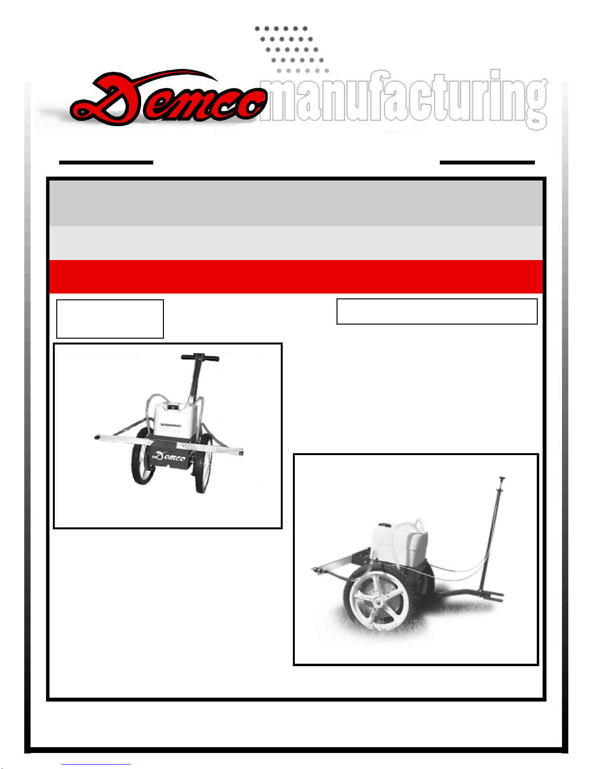
LA WN WIZARD
5 GALLON LA WN & GARDEN SPRAYER
OPERA TORS MANUAL
ASSEMBLY
CALIBRATION
OPERATION
REPLACEMENT PARTS
READ complete manual CAREFULLY
BEFORE attempting operation.
DEMCO Dethmers Mfg. Co. 4010 320th St. P.O. Box 189 Boyden, IA 51234
PH: (712) 725-2311 or (712) 725-2302 Toll Free: 1-800-543-3626 FAX: 1-800-845-6420
www.demco-products.com
Page 1
Page 2

Page 2
Page 3

Thank you for purchasing a Demco sprayer. We feel you have made a wise choice and hope you are
completely satisfied with your new sprayer. If you have any questions regarding the applications of
certain solutions or chemicals, contact your chemical supplier and follow chemical manufacturer
recommendations as well as all licensing and use restrictions or regulations.
W ARNING: TO AVOID PERSONAL INJURY OR PROPERTY DAMAGE, OBSERV E
FOLLOWING INSTRUCTIONS:
Chemicals are dangerous. Know exactly what you're going to do and what is
going to happen before attempting to work with these products. Improper
selection or use can injure people, animals, plants and soil.
Always wear protective clothing such as coveralls, goggles and gloves when
working with chemicals or sprayer.
Be sure to dispose of all unused chemicals or solutions in a proper and
ecologically sound manner.
GENERAL INFORMATION
1. Whenever terms "LEFT" and "RIGHT" are used in
this manual it means from a position behind sprayer
and facing forward.
2. When placing a parts order, refer to this manual for
proper part numbers and place order by PART NO.
and DESCRIPTION.
T able of Contents
General information............................................................................................................3
Safety Sign Location ..........................................................................................................4
Assembly and Maintenance Instructions for Lawn Wizard ................................................5
Lawn Wizard (5 gallon) Parts Breakdown (Models PSL51 and PSL52).............................6
Lawn Wizard (5 gallon Push Type) Parts List ....................................................................7
Lawn Wizard (5 gallon) Parts Breakdown (Models TRL51 and TRL52) .............................8
Lawn Wizard (5 gallon Pull Type) Parts List ...................................................................... 9
Important Care Instruction ................................................................................................ 10
Notes.................................................................................................................................11
Page 3
Page 4

SAFETY SIGN LOCATIONS
Types of safety sign and locations on equipment are shown in illustration below. Good safety
requires that you familiarize yourself with various safety signs, type of warning, and area or
particular function related to that area, that requires your SAFETY AWARENESS.
WARNING
To prevent serious injury or death
ï Refer to chemical supplier and manufacturer recommendations as well as all
licensing restrictions or regulations.
ï Always wear recommended protective clothing when working with chemicals or
sprayer.
ï Be sure to dispose of all unused chemicals or solutions in proper and ecologically
sound manner. Improper use can injure people, animals, plants and soil.
04/99 AB21014
Replacement part number for
Chemical Safety Sticker is
AB21014
Page 4
Page 5

ASSEMBLY AND MAINTENANCE INSTRUCTIONS FOR LAWN WIZARD
1. Remove all parts from the shipping container
Push Sprayer Handle Assembly (See page 6)
2. Assemble the top handle (#6) and bottom handle (#37) using the handle splicer (#38). four 1/4" x 1-1/2" bolts (#7)
and four 1/4" locknuts (#2).
3. Fasten the handle assembly into the frame channel on the main frame (#27) using two 1/4" x 1-1/2" bolts
(#7) and two 1/4" locknuts (#2).
Trailer Sprayer Tongue Assembly (See page 8)
2. Assemble pull tongue (#4) into the frame channel on the main frame (#27) opposite the brass control valves
(#12) using two 1/4" x 1-1/2" bolts (#7) and two 1/4" locknuts (#2).
3. Attach pull sprayer cable mount (#3) to the pull tongue (#4) using a 1/4" square u-bolt (#5) and two 1/4"
locknuts (#2). (Model TRL52 only)
4. For the double nozzle boom, attach boom mount (#31) and boom wings (#30) to the end of the main frame (#27)
opposite the brass valves (#12) using two 1/4" x 1/2" bolts (#34), two 1/4" nylon flatwashers (#44) and two
1/4"nylon locknuts (#2). Push the 3/8" vinyl hose (#26) onto the 3/8" hose barb (#28).
5. For the single nozzle boom, attach the single nozzle boom (#31) to the main frame using two 1/4" nylon
flat washers (#44), two 1/4" x 1/2" bolts (#34) and two 1/4" locknuts (#2).
6. On model PSL52 and TRL52 tie the control cables to the handle using plastic hose tie (Not Shown).
7. Sprayer is shipped with the pump hoses removed from wheel rollers. Before attempting to use sprayer
be sure to reinstall pump hoses (#18) by stretching them over the wheel rollers (#21). (See Photo below)
8. Make sure the suction hoses (#8) are in the holes provided in the top of the tank (#10).
9. Fill the sprayer tank (#10) with water.
10. All sprayers are equipped with AN10 nozzles (#32) for application at approximately one gallon per 1000 sq. ft.
11. The latex pump hoses (#18) should be checked periodically for signs of excessive stretching and wear.
NOTE: For correct spray pattern the sprayer
must be pushed or pulled at 2 to 2-1/2 MPH.
12.00
72.00
84.00
Page 5
Page 6

LA WN WIZARD (5 GALLON) SPRAYER P ARTS BREAKDOWN
FOR MODELS PSL51 AND PSL52
8
1
4
3
25
24
24
2
1
4
2
24
43
39
5
6
2
38
7
7
37
7
20
21
2
21
22
MODELS PSL51 AND PSL52
8
2
17
15
33
13
29
40
36
2
16
17
18
20
19
11
12
2
14
2
40
16
18
WHEEL ASSEMBLY
11
12
9
27
36
28
13
33
29
10
26
19
29
34
2
24
32
33
39
24
44
44
44
30
24
25
31
24
24
29
25
32
33
24
2
44
34
26
44
35
44
43
28
30
35
19
20
21
22
39
2
2
43
PART NO. 5368
Page 6
Page 7

LA WN WIZARD (5 GALLON) PUSH TYPE SPRAYER PARTS LIST
REF. PART QTY. REQ'D
NO. NO. SGL. DBL. DESCRIPTION
1. 05513 - 2 Push Pull Control Cable Assembly (w/ washers and nuts)
2. 02772 8 14 1/4" Nylon Insert Lock Nut
3. 05523-70 - 1 Push Sprayer Cable Mount
4. 05514 2 2 1-1/4" x 4-1/2" Black PVC Handle Grip (not shown)
5. 04822 - 1 1/4"- UNC x 1" Square U-bolt
6. 05518-70 1 1 Top Handle
7 00684 6 6 1/4-20 UNC x 1-1/2 Hex Head Bolt
8. G380 2.67ft 5.34ft 3/8" EVA Tubing (sold by foot)
9. PL2 1 1 Cap
10. P5 10 1 1 Tank - 5 Gallon w/ Cap
11. A3838 1 2 3/8" MPT x 3/8" Hose Barb
12. 05516 1 2 3/8" FPT x 3/8" FPT Brass Valve
13. K8400 3/8 1 2 3/8" Metering Barb
14. 05378 - 2 Control Cable Clamp
15. 00516 - 2 1/4" - 20 UNC 3/4" Flat Head Slotted Machine Screw
16. A3812 1 2 3/8" MPT x 1/2" Hose Barb
17. B8PH 2 4 #6 (0.500) Hose Clamp (Nylon)
26. 380 1.67ft 3.34ft 3/8" x 1/8" Wall Vinyl Hose (sold by foot)
27. 05860 1 1 Main Frame
28. NTL38 1 2 3/8" Elbow Spray Nozzle Fitting w/ Lock Nut
29. B12 2 4 Nozzle Lock Nut
30. 05750 - 2 Boom Wings - Lexan
31. 05751-70 1 1 Boom Mount/Single Nozzle Boom
32. AN10 1 2 AN10 Nozzle
33. 8027 2 4 11/16" FPS Swivel Nut
34. 00092 2 2 1/4" - 20 UNC x 1/2" Bolt
35. 01076 - 2 1/4" - 20 UNC x 3/4" Hex Head Bolt
36. 3812D 1 2 1/2" Hose Barb Straight Nozzle Fitting (Special Fitting)
37. 05862-70 1 1 Bottom Handle for PSL51 or PSL52
38. 05520-70 1 1 Handle Splicer
40. 07609 1 2 16mm Flatwasher
43. 10172 1 - Solid Rubber Tire
44. 05376 2 6 1/4" Nylon Flatwasher
- NHT11 - 1 Plastic Hose Tie
- 5368 1 2 Wheel Assembly-16" Wheel
2. 02772 7 14 1/4" Nylon Insert Lock Nut
18. 05515 1 2 1/2" x 1/8" Wall Black Latex x 17-1/4" Lg.
19. 05325-95 1 2 Wheel - Frame Spacer Bushing for 16" Wheel
20. 02004 4 8 1/4"- 10 UNC x 2-1/4" Stainless Steel Bolt
21. 05511 8 16 Nylatron Pump Hose Roller
22. 02000 4 8 1/4"- 20 UNC Stainless Steel Nut
24. 01906 3 6 1/4" - 3/4" Slotted Head Truss Bolt
25. 04993 1 2 1/2" Push Nut Washer Cap Type
39. 05509-95 1 2 Pump Roller Disk
43. 10172 1 2 Solid Rubber Tire
Please order replacement parts by PART NO.and DESCRIPTION
NOTE: Wheel Assembly Number 5368 includes only one wheel, and all other
quantities as listed in single nozzle column.
Page 7
Page 8

LA WN WIZARD (5 GALLON) SPRAYER P ARTS BREAKDOWN
FOR MODELS TRL51 AND TRL52
8
8
9
25
24
24
24
1
1
29
13
2
18
36
17
10
33
11
12
27
40
16
28
26
19
29
34
24
39
44
30
44
2
31
44
34
35
26
44
44
35
2
44
32
33
30
28
24
24
25
29
32
33
3
2
33
4
5
7
2
20
21
39
2
2
22
19
20
21
11
13
12
29
2
15
14
36
40
16
17
18
WHEEL ASSEMBLY
MODELS TRL51 AND TRL52
43
24
25
24
24
21
19
20
2
22
39
2
PART NO. 5368
Page 8
43
Page 9

LA WN WIZARD (5 GALLON) PULL TYPE SPRAYER PARTS LIST
REF. PART QTY. REQ'D
NO. NO. SGL. DBL. DESCRIPTION
1. 05513 - 2 Push Pull Control Cable Assembly (w/ washers and nuts)
2. 02772 4 10 1/4" Nylon Insert Lock Nut
3. 05524-70 - 1 Trailer Cable Mount
4. 04751-70 1 1 Pull Tongue
5. 04822 - 1 1/4"- UNC x 1" Square U-bolt
7 00684 2 2 1/4-20 UNC x 1-1/2 Hex Head Bolt
8. G380 2.67ft 5.34ft 3/8" EVA Tubing (sold by foot)
9. PL2 1 1 Cap
10. P5 10 1 1 Tank - 5 Gallon w/ Cap
11. A3838 1 2 3/8" MPT x 3/8" Hose Barb
12. 05516 1 2 3/8" FPT x 3/8" FPT Brass Valve
13. K8400 3/8 1 2 3/8" Metering Barb
14. 05378 - 2 Control Cable Clamp
15. 00516 - 2 1/4" - 20 UNC 3/4" Flat Head Slotted Machine Screw
16. A3812 1 2 3/8" MPT x 1/2" Hose Barb
17. B8PH 2 4 #6 Hose Clamp (Nylon)
26. 380 1.67ft 3.34ft 3/8" x 1/8" Wall Vinyl Hose (sold by foot)
27. 05860 1 1 Main Frame
28. NTL38 1 2 3/8" Elbow Spray Nozzle Fitting w/ Lock Nut
29. B12 2 4 Nozzle Lock Nut
30. 05750 - 2 Boom Wings - Lexan
31. 05751-70 1 1 Boom Mount/Single Nozzle Boom
32. AN10 1 2 AN10 Nozzle
33. 8027 2 4 11/16" FPS Swivel Nut
34. 00092 2 2 1/4" - 20 UNC x 1/2" Bolt
35. 01076 - 2 1/4" - 20 UNC x 3/4" Hex Head Bolt
36. 3812D 1 2 1/2" Hose Barb Straight Nozzle Fitting (Special Fitting)
40. 07609 1 2 16mm Flatwasher
43. 10172 1 - Solid Rubber Tire
44. 05376 2 6 1/4" Nylon Flatwasher
- NHT11 - 1 Plastic Hose Tie
- 5368 1 2 Wheel Assembly-16" Wheel
2. 02772 7 14 1/4" Nylon Insert Lock Nut
18. 05515 1 2 1/2" x 1/8" Wall Black Latex x 17-1/4" Lg.
19. 05325-95 1 2 Wheel - Frame Spacer Bushing for 16" Wheel
20. 02004 4 8 1/4"- 10 UNC x 2-1/4" Stainless Steel Bolt
21. 05511 8 16 Nylatron Pump Hose Roller
22. 02000 4 8 1/4"- 20 UNC Stainless Steel Nut
24. 01906 3 6 1/4" - 3/4" Slotted Head Truss Bolt
25. 04993 1 2 1/2" Push Nut Washer Cap Type
39. 05509-95 1 2 Pump Roller Disk
43. 10172 1 2 Solid Rubber Tire
Please order replacement parts by PART NO.and DESCRIPTION
NOTE: Wheel Assembly Number 5368 includes only one wheel, and all other
quantities as listed in single nozzle column.
Page 9
Page 10

IMPORTANT CARE INSTRUCTION
FOR PUSH AND PULL TYPE SPRAYER
A. Always clean the unit thoroughly after each use. Push at least two gallons of clean
water through the sprayer after cleaning out the chemicals.
B. After each use make sure the valves and nozzle assemblies are flushed clean of
chemicals both inside and outside.
C. After flushing and washing the valve, place a drop of oil (#10 or equivalent) on the
control cable wire where it is attached to control valve and on the wire at the control
cable mount.
D. Remove pump hoses from the wheel rollers when the sprayer is not in use.
CAUTION IS NECESSARY WHEN APPLYING CHEMICALS: Always ask your
dealer or chemical supplier how to mix and apply chemicals. Always follow
chemical manufacturer instructions as well as all licensing and use restrictions
and regulations. Be sure to dispose of all unused chemicals or solutions in a
proper and ecological sound manner. Keep sprayer and chemicals away from
children and pets. Dethmers Manufacturing Company will not be responsible for
applications results or misapplication of chemicals. The User shall determine the
suitability of the product for his intended use and assume all risk and liability.
Page 10
Page 11

NOTES
Page 11
Page 12

TOLL FREE: 1-800-54DEMCO (1-800-543-3626)
DETHMERS MFG. COMPANY
P.O. BOX 189
4010 320th St., BOYDEN, IA. 51234
PH: (712) 725-2311 or (712) 725-2302
FAX: (712) 725-2380
Page 12
 Loading...