

Page 1
7-06
RD20010,Rev 6
1
Page 2

Introduction
Thank you for purchasing a Demco Kar-Kaddy. We feel you have made a wise choice and hope you
are completely satisfied with your new piece of equipment.
GENERAL INFORMATION
1. Unless otherwise specified, high-strength (grade 5)
(3 radial-line head markings) hex head bolts are
used throughout assembly of this piece of equipment.
2. Whenever the terms "LEFT" and "RIGHT" are
used in this manual it means from a position behind
the
Kar-Kaddy and facing forward.
TABLE OF CONTENTS
General Information ................................................................................................................................ Page 2
Safety, You can Live With.................................................................................................................... Page 3-7
Decal Location ........................................................................................................................................ Page 8
Bolt Torque ............................................................................................................................................. Page 9
Tongue and Ramp Assembly ............................................................................................................... Page 10
Fender Assembly .................................................................................................................................. Page 11
Wiring Diagram ..................................................................................................................................... Page 12
Testing Lights........................................................................................................................................ Page 12
Tongue Folding ..................................................................................................................................... Page 13
Folding Ramps................................................................................................................................. Page 14-15
Loading Angle Clearance Guide........................................................................................................... Page 15
Safety, Maintenance, & Important Loading Instructions ....................................................................... Page 16
Loading Instructions...................................................................................................................... Pages 17-19
Toe-In Adjustment................................................................................................................................ Page 20
DA91 Brake Actuator Parts Breakdown and List.................................................................................. Page 21
10" Self-Adjusting Brake Cluster Parts Breakdown and List ................................................................ Page 22
Brakes Line Parts Breakdown and List................................................................................................. Page 23
Kar-Kaddy Breakdown Parts Assembly Instructions .................................................................... Pages 24-25
Winch and Tilt-Bed Parts Breakdown................................................................................................... Page 26
Ramp Latch and License Plate Bracket Parts Breakdown ................................................................... Page 27
Fender Parts Breakdown ...................................................................................................................... Page 28
Winch, Tool Box, & Spare Tire w/Mounting Bracket (optional) Parts Breakdown and List .................. Page 29
Deflector, & Light Bar (optional) Parts Breakdown and List .................................................................. Page30
Product Warranty .................................................................................................................................. Page 31
Warranty Registration ...................................................................................................................... Page 33-34
3. When placing a parts order, refer to this manual for
proper part numbers and place order by PART NO.
and DESCRIPTION.
"Reporting Safety Defects"
If you believe that your vehicle has a defect
which could cause a crash or could cause injury or
death, you should immediately inform the National
Highway Traffic Safety Administration (NHTSA) in
addition to notifying Dethmers Manufacturing Company (DEMCO).
If NHTSA receives similar complaints, it may
open an investigation, and if it finds that a safety
defect exists in a group of vehicles, it may order a
recall and remedy campaign. However, NHTSA
cannot become involved in individual problems between you, your dealer, or Dethmers Manufacturing
Company (DEMCO).
To contact NHTSA, you may either call the
Auto Safety Hotline toll-free at
1-800-424-9393 (or 366-0129 in
Washington, D.C. area) or write to:
NHTSA,
U.S. Department of Transportation
Washington, D.C. 20590.
You can also obtain other information about
motor vehicle safety from the Hotline.
2
Page 3

SAFETY
T AKE NOTE! THIS SAFETY ALERT SYMBOL FOUND THROUGHOUT THIS MANUAL IS USED TO
CALL YOUR ATTENTION TO INSTRUCTIONS INVOLVING YOUR PERSONAL SAFETY AND THE
SAFETY OF OTHERS. FAILURE TO FOLLOW THESE INSTRUCTIONS CAN RESULT IN INJURY
OR DEATH.
THIS SYMBOL MEANS
ATTENTION
BECOME ALERT
YOUR SAFETY IS INVOLVED!
SIGNAL WORDS
Note the use of the signal words DANGER, WARNING and
CAUTION with the safety messages . The appropriate signal
word for each has been selected using the following
guidelines:
DANGER:
Indicates an imminently hazardous situation that, if not
avoided, will result in death or serious injury.
If you have questions not answered in this manual, or require additional copies, please contact your dealer or Dethmers
Mfg. Co., P.O. Box 189, 4010 320th Street, Boyden, IA 51234
ph: (712) 725-2311 Toll Free: 1-800-543-3626 Fax: (712) 725-2380 or 1-800-845-6420
http://www.demco-products.com
WARNING:
Indicates a potentially hazardous situation that, if not avoided,
could result in death or serious injury. It may also be used to
alert against unsafe practices.
CA UTION:
Indicates a potentially hazardous situation that, if not avoided,
may result in minor or moderate injury . It ma y also be used to
alert against unsafe practices.
REMEMBER
Your best assurance against accidents is a careful and responsible operator. If there is any portion of this manual
or method of operation you do not understand, contact your local authorized dealer or manufacturer.
3
Page 4

SAFETY...YOU CAN LIVE WITH IT
EQUIPMENT SAFETY GUIDELINES
Every year many accidents occur which could have been avoided by a few seconds of thought and a more
careful approach to handling equipment. You, the operator , can av oid many accidents by observing the following
precautions in this section. To avoid personal injury, study the following precautions and insist those working
with you, or you yourself, follow them.
Replace any caution, warning, danger or instruction safety decal that is not readable or is missing. Location of
such decals is indicated in this booklet.
Do not attempt to operate this KK460SS under the influence of alcohol or drugs.
Review the safety instructions with all users.
Operator should be a responsible adult. DO NOT ALLOW PERSONS TO OPERATE OR ASSEMBLE THIS
UNIT UNTIL THEY HA VE DEVELOPED A THOROUGH UNDERST ANDING OF THE SAFETY PRECA UTIONS
AND HOW IT WORKS.
Do not paint over , remov e, or def ace any safety signs or w arning decals on your KK460SS . Observe all safety
signs and practice the instructions on them.
Never exceed the limits of a Kar Kaddy SS If its ability to do a job safely is in question
DON'T TRY IT.
LIGHTING AND MARKING
It is the responsibility of owner to know lighting and marking requirements of local highway authorities and to
install and maintain equipment to provide compliance with regulations.
Light bar kits are available from your dealer or from manufacturer.
TIRE SAFETY
• Failure to follow proper procedures when mounting a tire on a rim can produce an explosion which may result
in serious injury or death.
• Do not attempt to mount a tire unless you have proper equipment and experience to do the job.
• Inflating or servicing tires can be dangerous. Whenever possible, trained personnel should be called to
service and/or mount tires.
• KK460SS tires must be inflated to recommended P.S.I. . See decal on KK460SS for correct pressure.
• Always order and install tires and wheels with appropriate type and load capacity to meet or exceed gross
weight of unit.
SAFETY SIGN CARE
• Keep safety signs clean and legible at all times.
• Replace safety signs that are missing or have become illegible.
4
Page 5

• Replacement parts that displayed a safety sign should also display current sign.
• Safety signs are available from your distributor, dealer parts department, or factory.
How to install safety signs:
• Be sure installation surface is clean and dry.
• Decide on exact position before you remove backing paper.
• Remove smallest portion of split backing paper.
• Align decal over specified area and carefully press small portion with exposed sticky backing in place.
• Slowly peel back remaining paper and carefully smooth remaining portion of decal into place.
• Small air pockets can be pierced with a pin and smoothed out using piece of decal backing paper.
BEFORE OPERATION:
• Carefully study and understand this manual.
• Keep wheel and lug nuts tightened to specified torque.
• Assure tires are inflated evenly.
• Give unit a visual inspection for any loose bolts, worn parts, or cracked welds, and make necessary repairs.
Follow maintenance safety instructions included in this manual.
• Be sure there are no tools lying on or in KK460SS
• Do not use unit until you are sure that area is clear, especially around children and animals.
• Don't hurry learning process or take unit for granted. Ease into it and become familiar with your new KK460SS
• Practice operation of your KK460SS and its attachments. Completely familiarize yourself and other
operators with its operation before using.
• Make sure that brakes are evenly adjusted (if equipped with brakes)
• Securely attach to towing vehicle. Use an appropriately sized and rated hitch ball and attach safety chains.
• Do not allow anyone to stand between tongue or hitch and towing vehicle when backing up to unit.
• Make sure tow rating on vehicle is high enough for what it is towing.
DURING OPERATION
• SAFETY CHAIN - Always follow state and local regulations regarding safety chains and auxiliary lighting
when towing. Be sure to check with local law enforcement agencies for your own particular regulations. Only
safety chains (not elastic or nylon/plastic tow straps) should be used to retain connection between towing
vehicle and towed unit in event of separation.
• Do not load towed vehicle with cargo. Towed vehicles exceeding weight limits will overload KK460SS and
may cause serious injury and damage.
• Criss cross safety chains under tongue, secure to mounting loops on towing vehicle.
5
Page 6
• Secure emergency brake actuator cable to mounting loop on towing vehicle.
• Beware of bystanders, PARTICULARLY CHILDREN! Always look around to make sure it is safe to start engine
of towing vehicle or move unit. This is particularly important with higher noise levels, as you may not hear people
shouting.
• NO PASSENGERS ALLOWED- Do not carry passengers anywhere on or in towed unit.
• When halting operation, even periodically, set towing vehicle parking brake, shut off engine, and remove ignition
key.
• Be extra careful on inclines.
• MANEUVER TOWING VEHICLE AT SAFE SPEEDS. Do not exceed 55 M.P.H.
• Avoid overhead wires or other obstacles. Contact with overhead lines could cause serious injury or death.
• Avoid loose gravel, rocks, and holes; they can be dangerous for unit operation or movement.
• Allow for unit length when making turns.
• Do not work under raised components or attachments unless securely positioned and blocked.
• Keep all bystanders and pets clear of work area.
• Operate towing vehicle from operators seat only.
• As a precaution, recheck hardware on KK460SS every 50 miles, and correct all problems. Follow
maintenance safety procedures.
FOLLOWING OPERATION
• Following operation, or when unhitching, stop towing vehicle, set parking brake, shut off
engine and remove ignition key.
• Store KK460SS in area away from human activity.
• Do not permit children to play on or around stored KK460SS.
• Make sure parked KK460SS is on hard, level surface.
• Wheel chocks may be needed to prevent unit from rolling.
HIGHW AY AND TRANSPORT OPERATIONS
• Adopt safe driving practices:
- Always drive at safe speed relative to local conditions and ensure that your speed is low enough for an emergency
stop. Do not exceed 55 M.P.H.
- Reduce speed prior to turns to avoid risk of overturning.
- Always keep towing vehicle in gear to provide engine braking when going downhill. Do not coast.
- Do not drink and drive!
• Comply with state and local laws governing highway safety.
6
Page 7

• Local laws should be checked for all highway lighting and marking requirements.
• Plan your route to avoid heavy traffic.
• Be a safe and courteous driver. Always yield to oncoming traffic in all situations, including narrow bridges,
intersections, etc.
• Watch for obstructions overhead and to both sides while transporting.
• Operate with maximum visibility at all times. Make allowances for increased length and weight of KK460SS when
making turns and stopping.
PERFORMING MAINTENANCE
• Good maintenance is your responsibility. Poor maintenance is an invitation to trouble.
• Make sure there is plenty of ventilation. Never operate engine of towing vehicle in a closed
building. Exhaust fumes may cause asphyxiation.
• Before working on KK460SS, stop towing vehicle, set parking brake, tur n off engine and remove ignition key.
• Always block wheels and never use a jack as sole support.
• Always use proper tools or equipment for job at hand.
• Use extreme caution when making adjustments.
• Follow torque chart in this manual when tightening bolts and nuts.
• Openings in skin and minor cuts are susceptible to infection from brake fluid.
Without immediate medical treatment, serious infection and reactions can occur.
• After servicing, be sure all tools, par ts and service equipment are removed.
• Do not allow grease or oil to build up on any step or platform.
• When replacing bolts, refer to owners manual for proper size and grade.
• Refer to bolt torque chart for head identification marking.
• Where replacement parts are necessar y for periodic maintenance and servicing, genuine factor y replacement
parts must be used to restore your KK460SS to original specifications. Manufacturer will not claim
responsibility for use of unapproved parts and/or accessories or other damages as a result of their use.
• If KK460SS has been altered in any way from original design, manufacturer does not accept any liability for
injury or warranty.
• A fire extinguisher and first aid kit should be kept readily accessible while perf orming maintenance on this KK460SS
7
Page 8
PINCH POINT
REV 0 DD21018
A. DD21018
WARNING
To prevent serious
injury or death.
Make sure tongue is in
forward locked position with
locking pin and retainer clip
properly installed before
hooking up or loading.
REV 0 DD21019
B. DD21019 QTY. 1
F. RD21008 QTY. 2
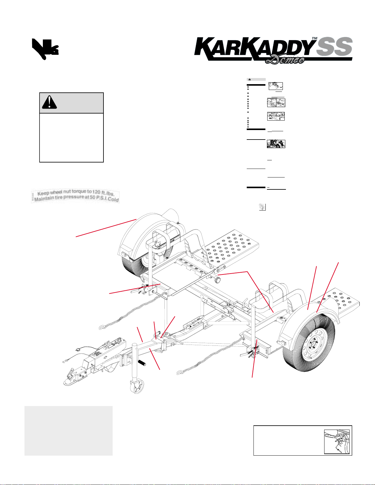
Decal Location
D. DD21017 QTY. 4
Loading Towed VehicleE
WARNING
Read towing instructions in towed vehicle
owners manual.
Use 2” 5000 lb. (or greater) capacity ball for Kar
Kaddy without surge brakes and 2” 6000 lb. (or
greater) capacity ball for Kar Kaddy with surge
brakes.
Assure towing vehicle parking brake is fully
engaged before starting hookup, loading,
unloading or unhooking Kar Kaddy.
Don’t load towed vehicle onto Kar Kaddy until Kar
Kaddy is completely and properly hooked up to
towing vehicle and setting on level surface.
Always drive front wheels of towed vehicle onto
Kar Kaddy. Don’t load backwards.
Tail lights and stop lights must be hooked up and
operating properly at all times.
Don’t load towed vehicle that exceeds weight or
size limits onto Kar Kaddy.
Always have someone safely guide you
when driving towed vehicle onto Kar Kaddy.
Assure tires of towed vehicle and Kar Kaddy are in
good condition and properly inflated. Tire pressure
may increase during travel, Do not bleed off this
increase in pressure.
Don’t back towing vehicle with Kar Kaddy
attached. Kar Kaddy swivels both at coupler and at
car platform. If you must back up, unload towed
vehicle first, disconnect Kar Kaddy and move
vehicle and Kar Kaddy separately. Play it safe...
park where you can pull ahead when leaving.
Braking distance increases when using Kar Kaddy.
Use caution and always allow sufficient braking
distance.
Avoid sharp turns or swerves.
Descend hills in lower gear. Avoid sudden braking
or lane changes when descending a hill.
Don’t transport passengers or cargo in vehicle
being towed.
Don’t unhook Kar Kaddy from towing vehicle
until towed vehicle is completely unloaded
from Kar Kaddy.
42” min.
42” min.
good condition and not rusted, loose or
stripped. Both hitch and hitch ball must
be securely attached to towing vehicle.
under tongue and attach
to mounting loops on
towing vehicle. If Kar Kaddy
is equipped with brakes
attach emergency brake
cable to one of these loops.
Allow some slack in chains
and cable for movement during turning.
Failure to follow these instructions could
result in serious injury or death.
1.Assure towing vehicle and Kar Kaddy are
straight, on level ground, and properly
hooked up before loading towed vehicle.
C
B
#2
A
2.Remove winch lock pins (A) from strap winches
on front of Kar Kaddy. RELEASE WINCH: Grasp
handle (B) squeeze trigger (C) push down and
pull all excess strap from winch. Lay tire strap
to outside of Kar Kaddy.
3. Remove STEERING LOCK PIN before loading
vehicle onto Kar Kaddy to allow AUTO STEER
WHEN KAR KADDY IS EMPTY, THIS
to operate.
PIN MUST BE REINSERTED
#3
4. Loosen wing nut on back of license plate holder,
turn clip on front to horizontal position and
put license in “down” position. Turn clip back
so it rests against back of light to hold license
“down” and tighten wing nut. (License must be
“up” with Kar Kaddy empty).
#5
5. Grasp bed release handle on tongue and
pull toward coupler. This releases tilt bed.
6. Before loading (and unloading) towed vehicle
make sure platform and towed vehicle are in
straight alignment. Don’t load towed vehicle
onto KAR KADDY until completely and properly
hooked up to towing vehicle and setting on
level surface.
7.With someone safely guiding you, center
vehicle to Kar Kaddy. Slowly drive vehicle
forward, until tires touch wheel stops at front
of platform. DO NOT BACK VEHICLE ONTO
KAR KADDY. Assure that towed vehicle is
centered on Kar Kaddy platform and tires fit in
wheel pans without hanging over sides.
8.Place towed vehicle in park (low gear if it has
standard transmission), engage parking brake,
shut off engine, remove ignition key, lock
steering wheel of towed vehicle with tires in a
straight forward position. If towed vehicle does
not have a locking steering column, steering
wheel must be securely tied.
#9
9.Place tire straps over tires centering straps and
winches to tires, avoiding contact with
suspension components. Short side of hook
must face rear of Kar Kaddy. While tightening
straps, pull cross straps forward to ensure even
tightening. Tighten straps until each tire starts
to flatten against tire stop. After strap is tight
and with ratchet handle in down (horizontal)
position insert lock pin through hole in ratchet
pawl arm
and ratchet frame then attach retainer
clip.
Hook safety chains to frame of towed
vehicle directly above area where chains are
mounted on Kar Kaddy.
IMPORTANT: Chains must not attach to or go
over steering or brake parts. Leave enough
slack in chains for suspension movement.
Check tire straps after first 5 miles of travel and
every 50 miles thereafter to ensure they are
tight and not rubbing or fraying on suspension
components of towed vehicle.
10. If towed vehicle is rear wheel or four wheel
drive, disconnect drive shaft. (Simply placing
transmission in neutral is not sufficient to
prevent damage to transmission). You must
disconnect drive shaft at rear axle and remove
it. With the drive shaft removed it will be
necessary to cap the transmission tail shaft to
prevent transmission fluid loss.
Rear engine/transaxle vehicle cannot be towed
with Kar Kaddy. (All vehicles loaded on Kar
Kaddy must be loaded with front of vehicle
facing forward). Consult your vehicle owner’s
manual to help determine if and how your
vehicle is suitable to be towed.
RELEASE
PARKING BRAKE ON TOWED VEHICLE.
11.
Ensure that steering wheel is locked in straight
forward position, remove ignition keys and
lock doors of towed vehicle.
12. Release parking brake on towing vehicle and
drive forward 100 feet. Stop and perform safety
check. Check hitch, hitch ball, ball coupler,
safety chains, tire straps, bolts and other items
to ensure they are tight and in correct position.
Check all lights to make sure they are operating
properly. Repeat safety check after first 5 miles
and every 50 miles thereafter.
NOTE: Do not unhook Kar Kaddy from towing
vehicle until towed vehicle is completely
unloaded from Kar Kaddy.
Unloading Towed Vehicle
1.Assure towing vehicle and Kar Kaddy are
straight, on level ground, and properly hooked
up before unloading towed vehicle.
2.Fully engage parking brake of towing and
towed vehicles.
3.If removed, reinstall drive shaft of towed
vehicle.
4.Straps may be “quick released” by removing
locking pin, grasping ratchet pawl and ratchet
handle simultaneously and pushing down
sharply. This process will permit easy removal
of strap from winch.
5.Remove tire straps and safety chains from
towed vehicle. Also release tilt bed as shown in
illustration #5.
6.Release parking brake of towed vehicle and
slowly back towed vehicle off Kar Kaddy.
7.On level ground check the transmission fluid
level of towed vehicle. Fluid may have leaked
out during towing.
8.Store safety chains and straps in
their storage position on each side.
9.Return tilt bed to locked position and reinsert
steering lock pin. As shown in illustration #3
#4
Read following information before hooking up,
loading, using, unloading or unhooking Kar
Kaddy to prevent property damage, serious
injury, or death.
IMPORTANT DO’S & DON’TS
IMPORTANT INFORMATION
Customer Responsibilities
Customer assumes all risks inherent in
operation, use, or possession of Kar Kaddy.
Towing a vehicle is owners responsibility and it
is the owner who must ensure that weight and
size limits of Kar Kaddy will not be exceeded by
vehicle being towed. Any injury or damage that
results from improper use or exceeding weight
or size limits is sole responsibility of owner.
Towing Vehicle Requirements
Owner assumes all responsibility for towing
vehicle’s fitness and suitability to perform
towing task in safe, legal, and reliable manner.
These responsibilities may include, but are not
limited to:
Towing vehicle weight being substantially
greater (at least 1000 lbs.) than weight of
Kar Kaddy and towed vehicle combined.
Compliance with towing restrictions as stated
by towing vehicle owner’s manual or
manufacturer.
Towing vehicle having minimum of 5000 lb.
hitch and hitch ball for Kar Kaddy without surge
brakes, or 6000 lb. hitch and hitch ball for Kar
Kaddy with surge brakes. Hitch ball must be 2”.
Do not use any other size hitch ball.
Towing vehicle’s hitch being approximately 18
inches to top of hitch ball. Make sure that hitch
and hitch ball are in good condition and not
rusted, loose or stripped. Both hitch and hitch
ball must be securely attached to towing
vehicle.
Towing vehicle must be in good condition.
Towing vehicle having a current federal or state
inspection where applicable, and complying
with any applicable laws.
Assure all lights are properly hooked up and
operating at all times.
Load Weight and Size Limits
Load weight is total weight of towed vehicle.
Overloading Kar Kaddy may cause serious injury
or damage to both towed vehicle and Kar Kaddy.
Maximum Towed Vehicle Weight.
KK260 KK260SB KK360 KK360SB
4400 lbs. 4700 lbs. 4400lbs. 4700lbs.
Size limit is overall width. Towed vehicle
exceeding size limit will obstruct platform’s
turning action when towing and could damage
towed vehicle’s tires and fenders.
KK260: 70” max.
KK360 76” max.
INSTRUCTIONS
Kar Kaddy Hook-Up
1.Assure towing vehicle parking brake is
fully engaged.
2.Loosen coupler lock, place coupler of Kar
Kaddy over 2” hitch ball on towing vehicle.
Assure coupler is fully seated on ball then
completely tighten coupler lock. Pull up on Kar
Kaddy tongue to assure it is properly secured.
NOTE: Assure that hitch and hitch ball are in
3.Connect Kar Kaddy wire harness to connector
on towing vehicle and check lights for proper
operation.
4. Criss cross safety chains
REV 1 RD21002
E. RD21002 QTY. 1
F
F
C
E
D
A
B
D
D
D
PULL & LIFT
TO
FOLD RAMP
Rev 0 DD21020
C. DD21020 QTY. 2
Remove winch lock pins (A) from strap winches on front of tow dolly.
Release winch: Grasp handle (B) squeeze trigger (C) push down and pull all
excess strap from winch. Lay tire strap to outside of tow dolly.
Tighten straps: Place tire straps over tires centering straps and winches to
tires. While tightening straps, pull cross straps forward to ensure even tightening.
Tighten straps until each tire starts to flatten against tire stop. After strap is tight,
insert lock pin into winch.
REV 1 DD21016
WINCH OPERATING INSTRUCTIONS
B
C
A
F. DD21016 QTY. 2
8
Page 9
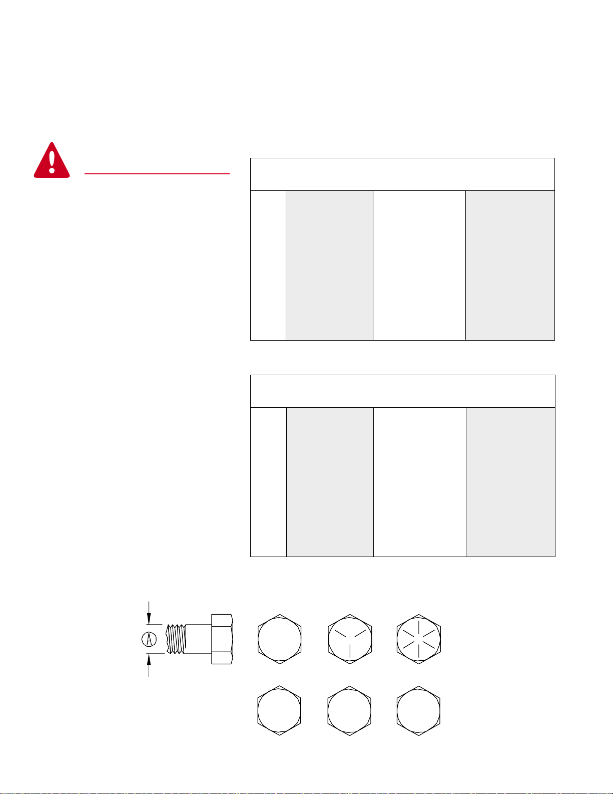
BOLT TORQUE
TORQUE DATA FOR STANDARD NUTS, BOLTS, AND CAPSCREWS.
Tighten all bolts to torques specified in chart unless otherwise noted. Check tightness of bolts
periodically, using bolt char t as guide. Replace hardware with same grade bolt.
NOTE: Unless otherwise specified, high-strength Grade 5 hex bolts are used throughout
assembly of equipment.
Bolt Torque for Standard bolts *
Torque Specifications
Torque Lug Nuts to 120 FT/LBS
Torque figures indicated are valid for
non-greased or non-oiled threads and
heads unless otherwise specified.
Therefore, do not grease or oil bolts or
capscrews unless otherwise specified
in this manual. When using locking
elements, increase torque values
by 5%.
* GRADE or CLASS value for bolts
and capscrews are identified by their
head markings.
GRADE 2 GRADE 5 GRADE 8
“A” lb-ft (N.m) lb-ft (N.m) lb-ft (N.m)
1/4” 6 (8) 9 (12) 12 (16)
5/16” 10 (13) 18 (25) 25 (35)
3/8” 20 (27) 30 (40) 45 (60)
7/16” 30 (40) 50 (70) 80 (110)
1/2” 45 (60) 75 (100) 115 (155)
9/16” 70 (95) 115 (155) 165 (220)
5/8” 95 (130) 150 (200) 225 (300)
3/4” 165 (225) 290 (390) 400 (540)
7/8” 170 (230) 420 (570) 650 (880)
1” 225 (300) 630 (850) 970 (1310)
Bolt Torque for Metric bolts *
CLASS 8.8 CLASS 9.8 CLASS 10.9
“A” lb-ft (N.m) lb-ft (N.m) lb-ft (N.m)
6 9 (13) 10 (14) 13 (17)
7 15 (21) 18 (24) 21 (29)
8 23 (31) 25 (34) 31 (42)
10 45 (61) 50 (68) 61 (83)
12 78 (106) 88 (118) 106 (144)
14 125 (169) 140 (189) 170 (230)
16 194 (263) 216 (293) 263 (357)
18 268 (363) -- -- 364 (493)
20 378 (513) -- -- 515 (689)
22 516 (699) -- -- 702 (952)
24 654 (886) -- -- 890 (1206)
GRADE-2 GRADE-5 GRADE-8
CLASS 8.8 CLASS 9.8 CLASS 10.9
8.8
9.8
9
10.9
Page 10
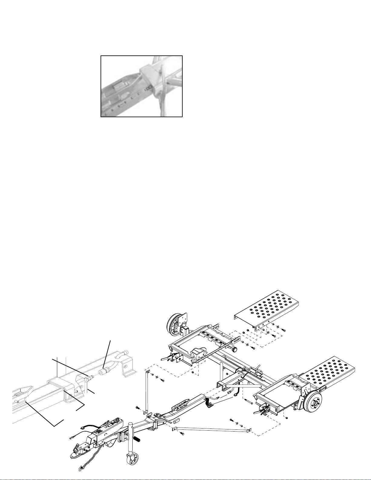
Tongue and Ramp Assembly Instructions
1. Place the main frame (#1) on blocks or some other sturdy
support so that the frame rests approximately 8" - 10" off
the ground.
2. With an assistant, place
tongue assembly (#2)
into main frame channel
and position latch on
tongue approximately 3”
from front of channel.
Clamp tongue to main
frame and support front
of tongue.
3. Locate the four bullet connectors extending out the back
of the tongue and plug into the connector protruding from
under the main frame channel. Plug into the flat four
connector by matching the colors. Do not cross colors
when making this connection. Make sure that the two
pigtails for the license plate bracket are out.
4. Using the open end of a 9/16” wrench to support the back
of the male coupler, (as shown below) push drip free quick
couplers together. (Factory setup units will not havequick
couplers)
5. With an assistant, mount the tongue assembly (#2) to the
front of the Kar Kaddy main frame and use a 5/8" x 4-1/2"
grade 5 bolt (#3) and lock nut (#4)(torque to 50 ft. lbs). Do
not torque over 50 ft. lbs. or bed will not tilt.
NOTE: Brake line and wiring must be above bolt also
coupler assembly must be ahead of bolt. Do this by
opening tongue about half way.
6. Lay the bracing struts (#5) out along the tow dolly tongue
with the back end (the end with the larger hole in it) of the
bracing strut toward the main frame. Loosely bolt the back
of each bracing strut to the trailer frame as shown using 1/
2" x 1-1/2" grade 5 bolt (#6), flatwasher (#7), pivot bushing
(#8) and locknut (#9). Hold up the front end (the end with
the smaller hole) of each bracing strut to the tongue and
secure with two 5/8" x 1-1/4" epoxied hex head bolts (#10)
and nut plate (#14). Torque the 1/2" x 1-1/2" bolt with the
pivot bushing to 75 ft. lbs. Torque the two 5/8" x 1-1/4"
epoxied hex head bolts to 100 ft. lbs.
7. On the main unit, pull ramp latch (#11) out and up in
unlatched position.
8. Use four 1/2” x 1-1/2” bolts (#6), 1/2” flat washers (#7) and
yellow plated bushings (#12) and place in the front slotted
hole and the rear slotted hole on both sides of ramp (#13).
Use four 1/2” nylon lock nuts (#9) and snug these bolts so
they can slide up and down in slot.
9. Place ramp (#13) in main frame (#1). Front bolts and
bushings go in front open slot of ramp mount. Lift ramp
up and push forward until rear bolts and bushings go into
rear half slot.
10. Engage Ramp latch (#11) and move ramp around so
latch can engage through ramp. With the use of two
clamps, secure ramp to main frame. Install the remaining
1/2” x 1-1/2” bolts (#6), flatwashers (#7), yellow bushings
(#12), and nylon lock nuts (#9) into the remaining slotted
holes.
11. Tighten all six bolts. Pull and lift ramp latch (#11) and pull
ramp back and fold up. If ramp is too tight when pulling
back, reclamp ramp as in previous step and loosen bolts
so ramp lowers away from main frame. Tighten bolts and
retry.
12. Repeat steps 7-11 for other side.
Connecting Drip Free Quick Coupler
brake couplers.
Not needed for factory setup units.
Female Coupler
Male Coupler
9/16 Wrench
5
10
3”
13
7
9
12
7
11
8
7
6
9
2
14
10
1
Connector
5
4
67
3
8
12
7
6
6
6
9
10
Page 11
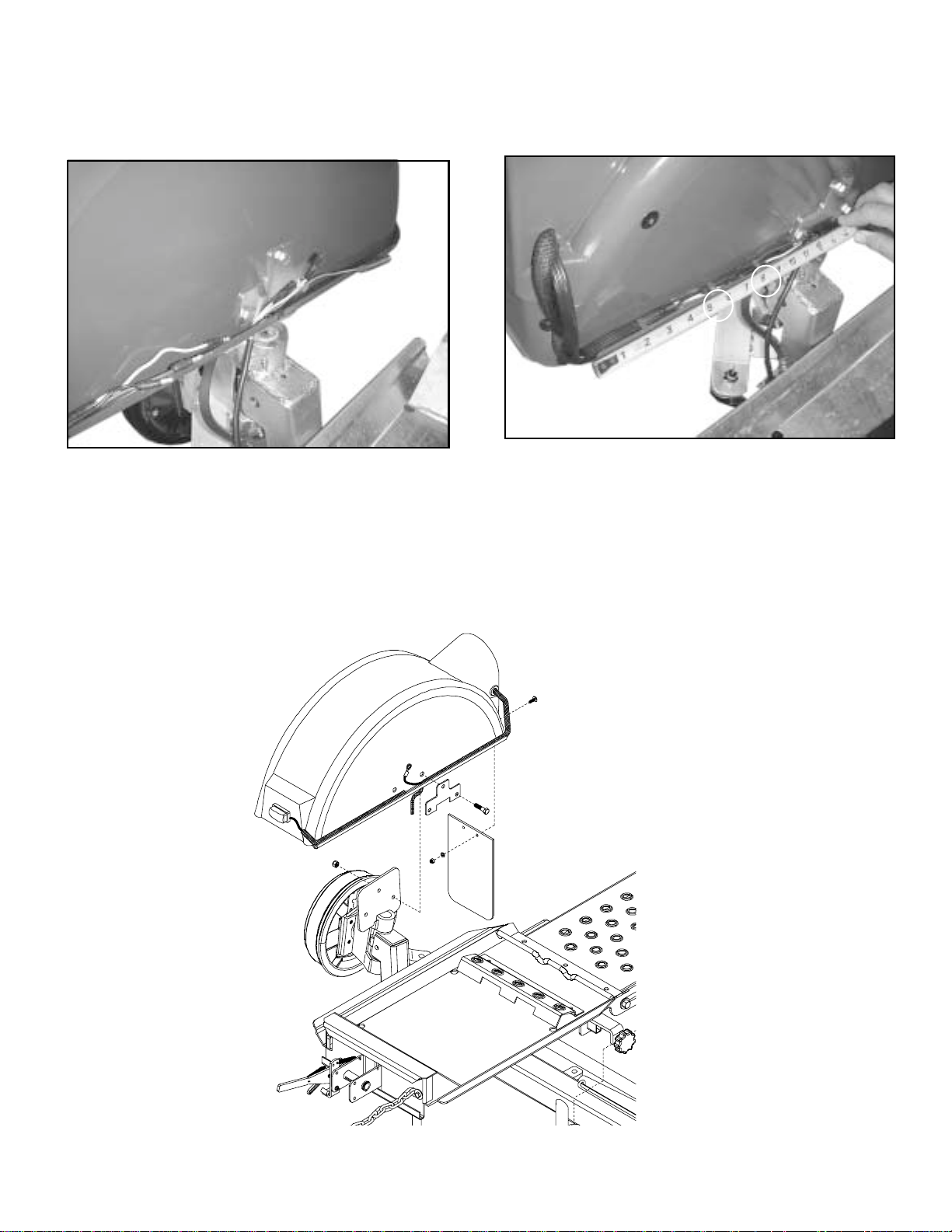
Fender Assembly Instructions
1. Install fender with fender backup plate (#1) and three 3/8”
x 1-1/2” bolts (#2). Put 3/8” nylon lock nuts (#3) inside of
fender and tighten.
2. Cut nylon wire tie from wiring to brake hose on main frame,
(used for shipping purposes only). Fish the three wires
from main unit through the hole in fender.
3. On the left side, plug in bullet plugs with white to white,
black to brown and yellow to red. On the right side, plug
white to white, black to brown and green to red.
4. With a pliers, install two wire clamps on fender. From rear
of fender lip, install one clamp at 5-1/2” and one at 8”.
5. Mount the mud flaps (#4) to the inside back of the fender
using two 1/4" x 3/4" truss head bolts (#5) with flat washers
(#6) and lock nuts (#7). Make sure the Kar Kaddy logo on
the flap faces the rear.
5
1
2
6
3
7
4
11
Page 12

Wiring Diagram
1
PARTS LIST
REF.
NO. PART NO. QTY. DESCRIPTION
1. 11590 1 Tongue Wiring Harness
2. 11591 1 Main Frame Wiring Harness
3. 01863 1 Rubber Grommet (not shown)
2
Please order replacement parts by PART NO. and DESCRIPTION.
TESTING LIGHTS BEFORE USE
1. Make sure that the WHITE ground wire is connected to the
frame of both the Kar Kaddy and the towing vehicle.
2. With headlights in "ON" position, the tail lights, the light
cluster bar, the license plate light, and the clearance lights
should be lighted.
3. Start engine and have someone depress brake pedal.
Brake lights of tow dolly and towing vehicle should come
"on" and "off" simultaneously with each application.
4. Turn left turn signal on. Left turn light of Kar Kaddy and
towing vehicle should flash simultaneously. If turn signal
light of the trailer function opposite to those of the towing
vehicle, it is probable that the YELLOW (Driver side) and
GREEN (Passenger side) wires have been reversed.
Check the plug connection under the tongue of the Kar
Kaddy to make sure wire colors are not crossed at that
point. If wires are crossed change them to match color for
color.
White
White
Brown
Yellow
Brown
Yellow
Green
Green
COLOR CODE FOR WIRING HARNESS
WHITE Ground
BROWN Tail Lights, License Plate Lights,
Light Cluster Bar & Clearance Lights
YELLOW Left Turn and Stop
GREEN Right Turn and Stop
WIRING OF THE TOWING VEHICLE
Connect wiring to towing vehicle, keeping in mind the color
code indicated below.
1. Make certain towing vehicle lights are "OFF".
2. Connect YELLOW wire to left turn signal and stop wire in
the left rear of towing vehicle with the wire splicer (01883)
supplied.
3. Connect GREEN wire to the right turn signal and stop
wire.
4. Connect BROWN wire to tail light wire.
5. VERY IMPORTANT - connect WHITE wire to frame body
of towing vehicle. This is the common ground, and a clean
metal - to - metal contact must be made.
CAUTION: Many flashers for vehicle turn signals will not
carry the additional load of Kar Kaddy turn signals. If
normal operation does not occur when connected to the
Kar Kaddy, a heavy duty replacement flasher may be
obtained through auto parts outlets.
12
Page 13

Tongue folding and storage
NOTE:
Tow Dolly must be empty and unhooked
to perform any and all of these steps. Do not
attempt while tow dolly is loaded or hooked up.
1. Pull retainer clip from bottom of tongue locking
pin. Lift locking pin out of tongue pivot.
2. With tongue wheel jack turned to its lowest
position, push/pull tongue to the left.
3. Push/pull tongue until it comes to a stop by
the left fender. It is recommended to place
lock pin and retainer clip back in tongue pivot
for storage.
13
Page 14

Folding Ramp Lock
NOTE:
Tow Dolly must be empty and unhooked
to perform any and all of these steps. Do not
attempt while tow dolly is loaded or hooked up.
1. Locate ramp locks at inside center of ramps.
2. Pull ramp lock straight out as far as it will go.
3. Lift ramp lock up as far as it will go and allow
lock to slide in until it stops.
4. If lock has been pulled and lifted properly the
ramp lock will extend out from it’s holder.
This will mean that the ramp is unlocked and
ramp may be folded up.
14
Page 15

Folding Ramp
NOTE:
Tow Dolly must be empty and unhooked
to perform any and all of these steps. Do
not attempt while tow dolly is loaded or
hooked up.
1. Pull ramp back as far as it will go. Bolt must be past
notch before attempting the next step.
2. Lift ramp until it is past center and resting on it stops.
IMPORTANT:
When taking this tow dolly out of storage it is very important to check all pins and retainers for damage. If damage is found
replace. Do not use damaged pins or retainers. Make sure that
tongue pin and retainer clip is replaced after tongue is folded back
to the forward and lock ed position. Fold ramps down as far as they
will go and push forward until you hear or see retainer handles
snap into their locked positions. Check to make sure they all fully
seated. Make sure that all pins and locking devices are double
checked before returning this unit to service.
Loading Angle Clearance Guide
NOTE: User’s responsibility for checking clearance
IMPORTANT:
Using this guideline will reduce the chance of the towed
vehicles air dam, or bottom of facia from interf ering with
tow dolly platform and or tire stop. “X” must be less
than 3-1/2 x “Y”.
Example: If Y measures 6”
3-1/2 x 6 = 21
X must measure less than 21”
15
Page 16

WARNING:
!
FAILURE TO FOLLOW THESE INSTRUCTIONS CAN RESULT IN LOSS OF TOWING VEHICLE CONTROL, SEPARATION
OF THE TOW DOLLY FROM THE TOWING VEHICLE, SEPARATION OF THE TOWED VEHICLE FROM THE TOW DOLLY,
CAUSING SEVERE PERSONAL INJURY, DEATH, OR PROPERTY DAMAGE.
!
Safety is of utmost importance at all times. There are several
items that must be checked each time before using and while
using the Kar Kaddy.
Make sure all bolts are properly tightened and those requiring
a set torque are up to specifications:
Tie Rod Castle Nut - 75 ft./lbs.
SAFETY
Lug Nuts - 120 ft./lbs.
Check Lug Nut tension after the first 5 miles and
periodically thereafter.
The ball hitch must latch securely around the ball and the
safety lock pin or lever must be in position to lock the hitch on
the ball.
RECOMMENDED BALL HEIGHT: 18 inches to the top of the
ball on the towing vehicle.
Hook the towed vehicle safety chains to the frame of the
vehicle directly above the area where the chain is mounted on
the Kar Kaddy. Leave some slack in the chain to allow
suspension movement.
Check to make sure that all lights are in proper working order.
Examine the winches and straps, making sure they are in
good conditon.
Rear Wheel Drive: Disconnect the towed vehicle driveshaft for
rear wheel drive vehicles with automatic transmission.
For manual transmission: Consult your vehicle owners manual
for towing suitability with the drive shaft connected.
MAINTENANCE
Periodically check all bolts and nuts to insure proper tension or
torque.
Grease the king pin and tie rod end grease zerks every 2500
miles.
An occasional drop of oil may be required on the moving parts
of the tie down winches.
A light film of oil should periodically be applied to steering
stabilizer arm to prevent rust.
NOTE: Proper toe-in is 1/32". This is preset at the factory.
The operator should periodically have the toe-in checked and
adjusted if needed at a qualified alignment shop. Improper toein can result in irregular tire wear.
Wheel:
This tow dolly comes equipped with chrome wheels. To
maintain a high gloss to the chrome, clean and wax with a
soft cloth regularly. Do not use an abrasive to clean chrome,
this will cause scratches and this will lead to rust.
IMPORTANT LOADING INSTRUCTION
Be certain the safety lock pins are locking the strap winches.
Retighten straps over the tires after the first 5 miles and every
50 miles thereafter. Ensure that they are tight.
The Kar-Kaddy tires must be inflated to the recommended 50
PSI.
The strap on the optional tongue winch must be in good
condition and should be stored neatly on winch when not in
use.
NOTE: The winch strap must not be left connected to the
towed vehicle after it is loaded and strapped down.
Make sure the optional light bar is fastened securely at the
rear of the towed vehicle.
The wires to the optional light bar should be run along the car
and fastened so as not to damage the finish of the towed
vehicle.
NOTE: This unit cannot be backed up, when loaded or with
the steering lock pin removed.
All vehicles mounted on the Kar Kaddy must be mounted with
the front of the vehicle facing forward.
Check your wheel tie-down straps.
Your Kar Kaddy is equipped with custom made wheel tie-down
straps of a standard size that will fit most tires, however if your
tires are too large or too small you will want to exchange these
new straps for the proper size straps.
1. Tire too large - This is very obvious the strap will not basket
over the tire properly, call us, we will provide at NO Charge
on an exchange basis, the proper size strap. You must
return your new unused straps and provide us with the
Make and Model car and the tire size.
2. Tire too small - This is not as obvious, the basket will fit
down over the tire very well, the problems cannot be
readily seen. You must tighten the straps down solid and
then check on the inside of the tire and be sure the strap,
when tightened does not come in contact with any metal
that may cause wear or cutting such as strut mounts. If
there is contact, you need a smaller strap, call us, we will
provide on a NO Charge, exchange basis, the proper size
strap. You must return your new unused straps and
provide us with the Make and Model car and tire size.
Thank you for Purchasing
Products.
16
Page 17

LOADING INSTRUCTIONS
.
Step 1. Secure ball coupler to 2" (5,000 lb. capacity) towing
vehicle ball only. Make sure that the hitch and the hitch ball
are in good condition and not rusted, loose or stripped.
Recommended ball height is 18" to the top of the ball.
Make sure hitch is locked down and secured with safety clip.
Criss-cross safety chains under tongue and secure to towing
vehicle frame.
Step 2. Remove black locking pin BEFORE loading vehicle
onto the Kar Kaddy. The removal of the locking pin allows
"Auto Steer" to operate. When towing the dolly empty, this pin
must be in place.
Step 4. Before loading (and unloading) towed vehicle make
sure platform and towed vehicle are in straight alignment.
Tow dolly must be completely and properly hooked up to the
towing vehicle. Towing vehicle must be larger and at least
1000 lbs. heavier than the tow dolly and towed vehicle
combined.
IMPORTANT: Over all width of towed vehicle must not
exceed:
76" max. (outside to outside),
42" min. (inside to inside),
78" max. (body width).
Step 3. Loosen wing nut on back of license plate holder, turn
the clip on the front to a horizontal position and put license in the
"down" position. Turn the clip back so it rests against the back
of the light bar to hold the license down and tighten wing nut.
(License must be "UP" with the tow dolly empty).
17
Page 18

Step 5. Grasp bed release handle on tongue and pull
toward coupler. This releases the tilt bed to permit loading.
Step 7. Drive vehicle onto the platform - front forward - until
tires touch the wheel stops at the front of each side of the
platform and the platform tilts to a flat position. Make sure the
car is centered on the platform. Towed vehicle tires must fit in
wheel troughs without overhanging sides. Engage towed
vehicle parking brake. Shift loaded car into "park" and lock
steering wheel with front tires in a straight position. If the
car does not have a locking steering column the steering
wheel must be tied securely with front tires in a straight
position.
Rear Wheel Drive: Disconnect towed vehicle driveshaft for
rear wheel drive vehicles with automatic transmission.
For manual transmission: Consult your vehicle owners
manual for towing suitability with the drive shaft connected.
Step 6. With someone safely guiding you, slowly drive vehicle onto platform FRONT FORWARD. (Any vehicle mounted
on tow dolly must be mounted with front of the vehicle facing
forward.) Drive the car forward until the tires touch the ramps.
Make sure the tire is aligned to ascend onto the ramps.
Step 8. Place one tie-down strap over each tire and secure
hooks to rods located at the rear of each wheel platform. The
short side of the hook must face the rear of the Kar Kaddy.
Step 9. Be sure tie-down winch is centered with the tire
before tightening straps.
18
Page 19

A
B
Step 10. Thread tie-down strap through the slotted tube on
the tie-down winch. Pull approx. 6" of strap through this slot.
Begin tightening strap making sure the tail becomes enclosed
by the strap coming over the tire. Tighten the straps ensuring
that the strap fed through the slot binds between the shaft and
the strap being wound onto the winch shaft. While tightening
straps, pull cross strap forward to ensure even tightening.
NOTE: Be sure to tighten straps until each tire starts to
flatten against tire stop. After each strap is tight, insert a
safety pin in each winch. Disengage towed vehicle parking
brake.
Straps must be retightened after first 5 miles of travel.
Check straps every 50 miles thereafter to ensure they are
tight and not rubbing or fraying.
Step 11. Make sure the tie-down strap is the correct size for
the auto tire. See page 4 of this instruction for proper fit and
exchange instructions.
Step 13. TO UNLOAD towed vehicle. Never unhook tow
dolly coupler from towing vehicle, before unloading
todolly. Make sure that platform and vehicle are straight.
Reinstall driveshaft. Ensure that towed vehicle parking brake
is fully engaged, then unhook the towed vehicle safety chains,
and release the tie-down straps. NOTE: Tie down straps
must be "quick -released" by grasping ratchet pawl (A) and
ratchet handle (B) simultaneously and pushing down sharply.
This process will permit easy removal of strap from winch.
Grasp bed release handle on tongue and pull toward coupler.
This releases the tilt bed to permit unloading. This will allow
the platform to tilt as you slowly drive off. Make sure the winch
ratchet handles are horizontal. Replace the "Auto Steer"
locking pin (for towing empty).
Step 14. To pull the Kar Kaddy empty, make sure "AutoSteer" LOCKING PIN IS IN PLACE and towing vehicle
safety chains are up and hooked. Tie-down winch handles
should be left in a down postion (horizontal position) with
safety pins in place when towing loaded or empty. DO NOT
ATTEMPT TO PULL KAR KADDY WITH WHEEL PLATFORM IN LOADING (tilted) POSITION.
DAMAGE PREVENTION
Check your vehicle manual or registration for vehicle weight.
Towing vehicle must be larger and at least 1,000 lbs. heavier
than the towed vehicle and tow dolly combined.
Do not pack goods in car that is being towed. Overloading the
Kar Kaddy or exceeding the width limit may result in damage
to both car and Kar Kaddy.
Step 12. Hook the towed vehicle safety chains to frame of
vehicle directly above the area where the chains are mounted
on the Kar Kaddy. Leave some slack in the chains to allow
suspension movement of the towed vehicle.
REAR WHEEL DRIVE PRECAUTIONS
Disconnect towed vehicle driveshaft for rear wheel drive
vehicles with automatic transmission. Simply placing transmission in neutral is not sufficient to prevent damage to
transmisssion.
For manual transmission: Consult your vehicle owners
manual for towing suitability with the drive shaft connected.
ALL VEHICLES MOUNTED ON THE KAR KADDY MUST BE
WITH THE FRONT OF THE VEHICLE FACING FORWARD.
SAFETY
• Examine winches and straps to make sure they are in
good condition.
• Check wheel nuts every trip.
• Tires must be inflated to recommended pressure by
tire manufacturer.
• Be certain the safety lock pins lock the strap winches.
• Retighten the straps over the tires after the first 5 miles
of travel. Check straps every 50 miles there after to
ensure they are tight and not rubbing or fraying.
19
Page 20

KAR-KADDY TOE-IN ADJUSTMENT
FRONT MEASUREMENT
(1/32" to 1/16" less than back measurement)
BACK MEASUREMENT
LOCKING
CLAMP
12"
18"
Ground
MEASURING THE TOE-IN
Have the tongue in a "hooked-up” position with the ball
coupler 18" off the ground. Jack up the axle just enough to
allow you to take the wheels off and put blocks under the axle.
Take the wheels off.
Find two 24" long bars. These could be a level, a square
or a straight piece of iron bar. Clamp one bar tight to the face
of each hub/Brake Drum with 12" extending forward and
backward of the center of the spindle. The bars must be
parallel to the platform the car sits on. Measure across the
back end of the bars and then across the front end. The front
measurement should be 1/32" to 1/16" less than the back
measurement. If the unit needs to be adjusted, this must be
done by adjusting the tie rod.
12"
C
L
TOE-IN ADJUSTMENT
1.
Put a mark on each side of the locking clamp on the tie rod.
2. Loosen the locking nuts on each end of the tie rod and
then the six bolts on the tie rod locking clamp.
3. Turn the tie rod whichever direction is needed until you
have a front measurement of 1/32" to 1/16" less than the
back measurement.
4. Hold the tie rod and tighten the locknuts on each end.
5. Measure again to make sure the toe-in measurement has
not moved.
6. Tighten the locking clamp bolts while holding clamp
between the marks you previously put on the tie rod.
7. Reassemble the rest of the Kar Kaddy unit.
20
Page 21

MODEL DA91 ACTUATOR PARTS BREAKDOWN
8
23
**12
**10
13
8
14
17
14
18
5398 Master Cylinder Repair Kit
(gasket included)
not included
28
4
5696
Coupler Repair Kit
2
9
2
1
3
2” Lever Lock Coupler
RATED AT 6000#
BLEEDING THE SYSTEM
The first requirement for safe, sure hydraulic braking is the use
of quality brake fluid. Use only DOT-3 or DOT-4 brake fluid
from a sealed container.
If pressure bleeding equipment is available, follow the
manufacturer’s instruction in bleeding the system.
If system must be bled manually, proceed as follows: Fill
master cylinder with fluid. Install bleeder hose on first wheel
cylinder to be bled.
Have loose end of hose submerged in brake fluid in glass
container to observe bubbling.
By loosening the bleeder screw located in the wheel cylinder
one turn, the system is open to the atmosphere through the
passage drilled in the screw. Pump actuator with long steady
strokes. The bleeding operation is completed when bubbles no
longer rise to the surface of the fluid. Be sure to close bleeder
screw securely.
Repeat bleeding operation at each wheel cylinder. During the
bleeding process, replenish the brake fluid, so the level does
not fall below the 1/2 full level in the master cylinder reservoir.
After bleeding is complete, make sure master cylinder reservoir
is filled and filler cap is securely in place.
After the bleeding operation has been completed, apply pressure to the system and check the whole brake system for leaks.
28
27
**16
15
15
25
9
26
6
7
9
20
21
5
24
19
Model 91 ACTUATOR PARTS LIST
REF.
NO. PART NO. QTY. DESCRIPTION
1. 09417 1 6000# 2" Lever Lock Coupler (zinc plated)
2. 01896 3 1/2"-13UNC x 4" Hex Head Bolt (gr.5)
3. 02178 3 1/2"-13UNC Nylon Insert Lock Nut
4. 05426 1 Front Shock Pin (drop tube actuators)
5. 11079-95 1 Drop Tube Actuator Slider (plated)
6. SB12426 1 Damper/ Shock
7. 11164-95 1 3 Bolt Mount Outer Case (plated)
8. 05424 2 5/16" External Tooth Lock Washer
9. 02363 2 5/32" x 1 1/4 Cotter Pin(Qty 3 w/drop tube)
**10. 05408 1 3/32" Cable with hooks
**12. 05693-95 1 Emergency Lever Spring (plated)
13. 05961 2 5/16"-18UNC x 5/8" Hex Head Bolt (gr.5)
14. 00618 4 1/4-20UNC x 2" Hex Head Bolt (gr.5)
15. 00057 4 1/4" Lock Washer
**16. 05951 1 Emergency Lever Assembly
17. 03876 1 Master Cylinder Cap w/ Diaphragm & O-ring
- 05849 1 O-Ring Only (not shown)
18. 05977 1 Push Rod Assembly
19. 00062 4 1/4”-20 UNC Hex Nut
20. 09153 - Plastic Master Cyl. Gasket ONLY
21. 10616 1 Master Cylinder
22. SB12098 1 .018 Connector Orifice (Drum Brakes)
23. 03866-95 1 Lever Guide (plated)
24. 05687 1 Master Cylinder Protective Boot
25. 05986-95 1 Connecting Pin (plated)
26. 10965 1 Upper Slider
27. 10966 1 Lower Slider
28. 10967 2 Side Spacers
- 5401 - Lever Replacement Kit (incl. items w/**)
- 5650 - Master Cyl. Replacement Kit (drum)
- 5696 - Coupler Repair Kit
Please order replacement parts by PART NO. and DESCRIPTION
22
19
21
Page 22

10" SELF-ADJUSTING BRAKE CLUSTER and DRUM PARTS BREAKDOWN
4
5
5
7
16
1
6
4
16
2
3
2
8
11
13
10
3
12
19
9
10
17
18
15
17
BRAKE CLUSTER PARTS LIST
REF. PART
NO. NO. QTY. DESCRIPTION
- SB24429M - Left Hand Cluster (shown above)
- SB24428M - Right Hand Cluster
1. SB23871 1 Back Plate Assembly
2. SB9254 2 Cover Plate - Adjusting Hole
3. SB10954 1 Brake Shoe Kit (includes 2 Primary & 2 Secondary)
4. 04305 2 5/16"-18UNC-Gr5 x 1/2" Hex Hd Bolt
5. 05424 2 5/16" External Tooth Washer
6. SB9776 1 Wheel Cylinder Assembly - Right
- SB9777 1 Wheel Cylinder Assembly - Left
7. 05431 1 Bleeder - replacement
8. SB9783 1 Push Rod
9. SB24047 1 Adjusting Screw Assembly - "R" (for LEFT cluster)
- SB24048 1 Adjusting Screw Assembly - "L" (for RIGHT cluster)
10. SB10958 2 Spring - Shoe
11. SB10961-95 1 Shoe Guide
12. SB23937 1 Cable
13. SB23936 1 Cable Guide
14. SB23724 1 Spring - Adjusting Screw
15. 05415-95 1 Lever - Right
- 05414-95 1 Lever - Left
16. SB10959 2 Pin - Shoe Hold Down
17. SB9789 4 Cup Shoe Hold Down
18. 05983 2 Spring - Shoe Hold Down
19. 03380 1 Spring
14
17
18
17
- SB15845 1 Wheel Cylinder Repair Kit
- SB40929 2 10" Brake Drum
Please order replacement parts by PART NO. and DESCRIPTION.
Brake shoe kit can be ordered for one complete axle only.
(includes spring, cup and boot)
22
Page 23

SURGE BRAKES PARTS BREAKDOWN
13
12
11
11
8
10
17
4
5
4
3
13
1
9
7
6
10
11
11
18
2
Model DA91
Brake Actuator
SURGE BRAKES FIELD SETUP PARTS LIST
REF. PART
NO. NO. QTY. DESCRIPTION
1. 11968 1 6" Brake Line
2. 02034 1 45” Brake Hose
3. SB512 1 12” Brake Line
4. 05679 2 Brake Fitting
5. 11617 1 Male Coupler
6. 11618 1 Female Coupler
7.
11643
8. SB7785 1 Brake Line Tee
9. 05960 1 5/16” x 1/2” Self-threading Bolt
10. SB541 2 41” Brake Line
11. 02549 6 Rubber Protector
12. 02032 2 12” Brake Hose
13. SB7764 3 Brake Line Clip
14. SB24429 1 Left Brake Cluster
-- SB24428 1 Right Brake Cluster
15. SB40929 2 10” Brake Drum
16. 04174 4 Retainer Washer
17. 01863 1 Rubber Grommet
18. 12445-30 1 Spring Return System
Please order replacement parts by PART NO. and DESCRIPTION.
1 7" Brake Hose Swival Male/Solid Male
14
16
15
SURGE BRAKES FACTORY SETUP PARTS LIST
REF. PART
NO. NO. QTY. DESCRIPTION
1. 11968 1 6" Brake Line
2. 02034 1 45” Brake Hose
3. 12449 1 15” Brake Line
4. N/A 2 Brake Fitting
5. N/A 1 Male Coupler
6. N/A 1 Female Coupler
7.
SB7H67
8. SB7785 1 Brake Line Tee
9. 05960 1 5/16” x 1/2” Self-threading Bolt
10. SB541 2 41” Brake Line
11. 02549 6 Rubber Protector
12. 02032 2 12” Brake Hose
13. SB7764 3 Brake Line Clip
14. SB24429 1 Left Brake Cluster
-- SB24428 1 Right Brake Cluster
15. SB40929 2 10” Brake Drum
16. 04174 4 Retainer Washer
17. 01863 1 Rubber Grommet
18. 12445-30 1 Spring Return System
Please order replacement parts by PART NO. and DESCRIPTION.
1 7" Brake Hose, Swival Male/Solid Female
BLEEDING THE SYSTEM
The first requirement for safe, sure hydraulic braking is the use
of quality brake fluid. Use only DOT-3 or DOT-4 brake fluid
from a sealed container.
Only use pressure bleeding equipment and follow the
manufacturer’s instruction in bleeding the system.
23
Page 24

KK460SS PARTS BREAKDOWN
2
1
4
5
60
6
50
55
56
57
54
58
24
7
11
6
10
41
13
9
20
23
12
19
21
22
75
46
47
48
45
46
26
23
26
52
28
22
27
53
41
25
21
43
52
39
29
38
40
53
36
37
20
19
19
21
60
71
76
59
21
49
61
58
56
64
63
62
65
26
32
24
37
24
51
32
Page 25

REF. PART
NO. NO. QTY. DESCRIPTION
1. 03528 2 Tie-down Strap assembly, Black
2. 5737 1 Right Fender Assembly with Lights
3. 5736 1 Left Fender Assembly with Lights
4. 04424-95 2 Fender Backing Plate
5. 00914 6 3/8”-16UNC x 1-1/2” Hex Head Bolt (gr.5)
6. 02592 18 3/8”-16UNC Nylon Lock Nut
7. 04165-80 1 Right Wheel Carrier
8. 04166-80 1 Left Wheel Carrier
9. 01732 4 1"I.D. x 1-1/4"O.D. x 1-1/2"lg. Bushing (brnz)
10. 11588 2 King Pin (1” x 6-1/2”)
35
27
33
32
31
26
6
30
6
34
21
15
18
16
19
14
17
3
8
72
67
22
19
66
35
73
44
34
21
74
22
34
21
42
68
22
REF. PART
NO. NO. QTY. DESCRIPTION
11. 01731 4 1-1/4" Dust Cap
12. 05587 2 1" I.D.x 14 GA Narrow Rim Machine Washer
13. 11566-80 1 Right Drop Axle Mount
14. 11550-80 1 Left Drop Axle Mount
15. 11551 2 King Pin Retainer Bolt
16. 03724 2 7/16”-20UNF Center Punched Nut
17. 02377 8 7/16”-20UNF x 1-1/2” Epoxy Bolt (gr.8)
18. 04168 8 7/16”-20UNF Nylon Lock Nut
19. 02178 18 1/2”-13UNC Nylon Lock Nut
20. 02579-95 2 Pivot Bushing
21. 00085 15 1/2" Flatwasher
22. 01254 15 1/2"-13UNC x 1-1/2" Hex Head Bolt (gr.5)
23. 02747-96 2 Bracing Strut
24. 03503 2 5/8”-11UNC x 1-1/4” Epoxy Bolt (gr.5)
25. 02434 1 5/8”-13UNC x 4-1/2” Hex Head Bolt (gr.5)
26. 02587 4 5/8”-13UNC Nylon Lock Nut
27. 02696 2 5/8"-11UNC x 2-3/4" lg. Hex Head Bolt (gr.5)
28. 00477 1 5/8" Flatwasher
29. 01729-30 1 Steering Stabilizer Shock
30. 11553-80 1 Tie Rod Clamp, Bottom
31. 11554-80 1 Tie Rod Clamp, Top
32. 00907 6 3/8”-16UNC x 1” Hex Head Bolt (gr.5)
33. 02494 2 3/8”-16UNC x 2-1/4” Hex Head Bolt (gr.5)
34. 11659-91 12 Ramp Bushing
35. 11529-96 2 Ramp
36. 01718-95 1 Tie Rod Locking Pin
- 02189 1 Replacement Black Handle Grip for Locking Pin
37. 00182 1 Hair pin
38. 11540-96 1 KK460SS Main Frame
39. 5740 1 License Plate Bracket Assembly
40. 04771-80 1 Tie Rod
41. 5179 1 Right Tie Rod End w\Right Hand Threads
42. 5178 1 Left Side Tie Rod End with Left Hand Threads
43. 01905 1 9/16"-18UNF Jam Nut w/Right Hand Threads
44. 01904 1 9/16"-18UNF Jam Nut w/Left Hand Threads
45. 04773-96 2 Rear tire Stop
46. 00523 4 3/8"-16UNC x 1-1/4" lg. Hex Head Bolt (gr.5)
47. 02243 1 Black Vinyl Hand Grip
48. 11978-96 1 Rear Tongue Half
49. 11969-96 1 Front Tongue Half
50. 5433 1 Right Winch assembly
51. 5432 1 Left Winch Assembly
52. 02772 2 1/4”-20UNC Nylon Lock Nut
53. 04176 2 1/4”-20UNC x 3/4" Carriage Bolt
54. 11967-95 1 5/8”-13UNC x 5 1/4” Hex Head Bolt (gr.5) Hinge Bolt
55. 11795 1 Pin, 5/8” x 4-7/8”
56. 01898 4 7/16”-14UNC x 1-1/4” Hex Head Bolt (gr.5)
57. 00078 2 7/16" Lockwasher
58. 00059 8 3/8” Flat Washer
59. 02771 2 7/16”-14UNC Nylon Lock Nut
60. 02383 4 36” Safety Chain
61. 02288-95 1 Bolt on Handle
62. 02189 1 Rubber Handle Grip
63. 01338 1 1/2"-12UNC x 4-1/2" lg. Hex Head Bolt (gr.5)
64. 01975 2 1/2"-12UNC x 5" lg. Hex Head Bolt (gr.5)
65. 11683 1 Wheel Jack
66. 04369 2 Hub and Spindle
- 02917 - Replacement 12mm x 1.50mm Stud Bolt
67. 02210 8 7/16”-20UNF x 1-1/4” Epoxy Bolt (gr.8)
68. 11913 2 ST205/75R14 "C"Range Radial Tire
69. 11574 2 Rim, 14 x 5.5, 5 on 115mm B.C.
70. 02933 10 Chrome Lug Nut
71. 5607 1 DA91 Actuator
72. SB24428 1 10” Brake Cluster, RH
- SB24429 1 10” Brake Cluster, LH
73. SB40929-30 2 10” Brake Drum
74. 04174 4 Retainer Washer
75. 11971-95 2 Nut Plate
76. 12445-30 1 Spring Return System
Please order replacement parts by PART NO. and DESCRIPTION.
25
70
69
Page 26

WINCH ASSEMBLY
5
1
2
Left Winch 5432 (Shown)
Right Winch 5433
14
18
3
4
- 5432 - Left Winch Assembly
- 5433 - Right Winch Assembly
1. 00214 11/4”Flat Washer
2. 01076 11/4”-20 UNC x 3/4” Hex Head Bolt
3. 01864 2 Spring
4. 02772 21/4”-20 UNC Nylon Insert Locknut
5. 05337 1 Lock Pin w/ Cable
6. 00004 2 5/16” Flat Washer
7. 02243 1 Black Vinyl Hand Grip
8. 05444 13/8”-16 UNC x 3/4” Hex Head Bolt w/ Epoxy
9. 05449 1 Winch Pawl Bushing (Stainless Steel)
10. 05450 1 Winch Pawl
11. 03572-95 1 Left Ratchet Pawl Arm
- 03573-95 1 Right Ratchet Pawl Arm
12. 03574-95 1 Ratchet Handle
13. 03575-95 1 Left Outer Ratchet Gear
- 03576-95 1 Right Outer Ratchet Gear
14. 03666 1 5/16” x 1-1/4” Roll Pin
15. 03668 11” x 18 Gauge Machine Washer
16. 03578 1 5/16”-18 UNC x 1/2” Socket Head Shoulder Bolt
17. 01998 1 5/16” Flat Washer (Stainless Steel)
18. 02002 11/4” Flat Washer (Stainless Steel)
11
7
12
17
16
3
9
6
8
10
15
13
TILT-BED LATCH ASSEMBLY
16
REF. PART
NO. NO. QTY. DESCRIPTION
5511 - Tilt-Bed Latch Kit
1*. 03434 1 5/16"-18 UNC x 4" Eye Bolt
2*. 04221 1 5/16"-18 UNC x 2-1/2 Hex Head Bolt (Gr 5)
3*. 00004 1 5/16" Flatwasher
4*. 00007 1 5/16"-18 UNC Hex Nut
5*. 03379-95 1 Latch Block
6*. 03435 1 Roll Pin (5/16" x 2-1/4")
7*. 03499 1 Latch Spring - Stainless Steel
8. 03382-95 1 Latch Handle Pivot Bushing
9. 03574-95 1 Latch Handle
10. 03381-95 1 Latch Catch
11. 03433 1 Latch Cable
12. 02802 1 5/16-18 UNC Nylon Insert Locknut
13. 00967 1 1/2"-13UNC x 1-1/4" lg. Hex Head Bolt (gr.5)
14. 00085 2 1/2" Flatwasher
15. 00059 1 3/8" Flat Washer
16. 02178 1 1/2"-13UNC Nylon Insert Locknut
17. 05449 1 Spacer Bushing - Stainless Steel
18. 05444 1 3/8"-16 UNC x 3/4" Epoxied Hex Bolt (Gr 5)
Please order replacement parts by PART NO. and DESCRIPTION.
* Items included in 5511 kit
14
11
2
10
13
18
12
15
8
17
1
6
5
4
3
7
9
KIT #5511
TILT-BED LATCH
14
ASSEMBLY
26
Page 27

RAMP LATCH ASSEMBLY
REF. PART
NO. NO. QTY. DESCRIPTION
5763 - Ramp Latch Kit
1. 11622-95 1 5/16"-18 UNC Latch Rod
2. 00007 2 5/16"-18 UNC Hex Nut
3. 00004 1 5/16" Flatwasher
4. 00059 1 3/8” Flatwasher
5
1
6
4
2
3
7
2
8
9
5. 11570-95 1 Latch Block
6. 11623-95 1 Threaded Bushing
7. 03499 1 Latch Spring - Stainless Steel
8. 02384 1 1/2” Narrow Machine Washer
9. 11621 1 Handle/Knob
Please order replacement parts by PART NO. and DESCRIPTION.
LICENSE PLATE BRACKET ASSEMBLY
REF. PART
NO. NO. QTY. DESCRIPTION
(not available)
4
5
3
2
2
3
1
10
4
7
8
6
6
9
10
7
10
5740
License Plate Mount
and Light Cluster
Please order replacement parts by PART NO. and DESCRIPTION.
5740 - License Plate Bracket and Light Assembly
1. 04505-95 1 License Plate and Light Cluster Bracket
2. 04176 2 1/4”-20UNC X 3/4” Carriage Bolt
3. 02214 2 #10 NC X 1/2” Slotted Truss Head Screw
4. 02163 1 Square License Plate Light w/Washer and Nut
- 02164 - Clear License Plate Light Lens Only
5. 02580-95 1 License Plate Clip
6. 02770 2 1/4”-20UNC Nylon Insert Wing Nut
7. 02205 2 #10 NC Nylon Lock Nut
8. 00214 1 1/4”-20UNC Flat Washer
9. 11687* 1 3 Cluster Light Bar Only (No Lights)
10. 11688* 3 Red LED Light
- 11655* 1 3 Cluster LED Wiring Harness
- 11616 1 Gromment, 5/8” OD x 3/8” x 1/8” Thick
- 5765 - 3 Cluster LED Light Assembly (* Included)
27
Page 28

Fender Assembly
8
6
1
11
14
9
2
2
2
2
2
3
10
4
13
15
19
17
12
16
PARTS LIST
REF.
NO. PART NO. QTY. DESCRIPTION
5736 - Left Fender Assembly
5737 - Right Fender Assembly
1. 01883 2 Wire Splicer
2. 04425 5 Tinnerman U-clamp
3. 04515 1 17-1/2” Wire Loom
4. 04643 2 9/16” x 5/8” Pop Rivet
5. 05443 1 Nylon Cable Hanger
6. 05447 1 4” Light Grommet
7. 11206 1 Tail Light Wire Harness
8. 11209 1 4” LED Tail Light
9. 11595 1 Left Fender Assembly
- 11596 1 Right Fender Assembly
10. 11604 1 Chrome LED Marker Base Mount
11. 11605 1 Yellow LED Marker Light
12. 11619 1 12” Wire Loom
13. 11654 1 Front Marker Wiring Harness
14. 04508 1 Amber Reflector
- 04804 1 Red Reflector
15. 07490 2 3/16” Washer
16. 01769 1 Kar Kaddy Mud Flap
17. 02772 2 1/4” Nylon Lock Nut
18. 05338 2 1/4” Slotted Truss Head Bolt
19. 00214 2 1/4” Flat Washer
Please order replacement parts by PART NO. and DESCRIPTION.
7
18
5
28
Page 29

OPTIONAL SPARE TIRE and MOUNT PARTS BREAKDOWN
Drive in stud here for
tire with rim #11574
(115mm bolt circle).
6
4
1
- 5734 1 Optional Spare Tire and Rim
1. N/A 1 ST205/75R 14"x"C" ROWL RadialTire
2. 11574 1 6" x 14" Chrome Rim 115mm Bolt Circle
PARTS LIST
3
7
8
2
5
* All options may not mount on tow dolly simultaneously.*
OPTIONAL TOOL BOX
RKSTM 1 Spare Tire Mounting Bracket
3. 02193-30 1 Spare Tire Bracket
4. 02917 1 Stud Bolt (12mm x 1.5)
5. 02933 2 Wheel Nut (12mm) Chrome
6. 02759 2 3/8"-16UNC Square U-Bolt
7. 00059 2 3/8" Flatwasher
8. 02592 4 3/8"-16UNC Nylon Insert Locknut
- KK6TC Optional Spare Tire Cover
Please order replacement parts by PART NO. & DESCRIPTION.
PARTS LIST
RKTB 1 Optional Tool Box
1. 00059 4 3/8" Flatwasher
2. 02592 8 3/8"-16UNC Nylon Insert Locknut
3. 01888-30 1 Tool Box
4. 00182 1 Small Hair Pin
5. 02742-30 2 Mounting "Z" Bracket
6. 00907 4 3/8"-16UNC x 1" Hex Head Bolt (gr.5)
7. 02759 2 3/8"-16UNC x 3" Square U-Bolt
Please order replacement parts by PART NO. and DESCRIPTION.
* All options may not mount on tow dolly simultaneously.*
29
7
7
2
1
6
5
2
4
3
Page 30

OPTIONAL LIGHT BAR PARTS BREAKDOWN
LIGHT BAR PARTS LIST
REF. PART
NO. NO. QTY. DESCRIPTION
RKLB Kar Kaddy Light Bar (complete)
1. 01772 2 Nylon Security Strap with hooks & tightener
2. 01857 1 Left Tail/ Brake and Signal Light w/Lenses
3. 01773 1 Brown Jumper Wire
4. 01886 4 Wire Holder (metal)
5. 02385-50 1 Light Bar Framework
6. 02386.50 2 Adjustable Light Bracket
7. 01856 1 Right Tail/ Brake and Signal Light w/Lenses
8. 02772 10 1/4"-20UNC Nylon Insert Locknut
9. 00092 6 1/4"-20UNC x 1/2" Hex Head Bolt
10. 01777-50 2 Light Bar "Z" Bracket
11. 01778 4 3" Suction Cup w/Bolt (#13)
12. 02198 1 Light Bar Wiring Harness (new style)
13. 00068 4 1/4"-20UNC x 3/4" Hex Head Bolt
14. 01911 - Large Red Lens
15. 01912 - Small Red Lens
16. 01890 - Clear Lens
Please order replacement parts by PART NO. and DESCRIPTION.
6
1
8
9
8
9
1
4
8
12
7
14
9
8
5
4
9
1
13
10
11
2
3
15
16
13
1
11
COLOR CODE FOR WIRING HARNESS
WHITE Ground
BROWN Tail Lights, License Plate Lights,
Light Cluster Bar & Clearance Lights
YELLOW Left Turn and Stop
GREEN Right Turn and Stop
OPTIONAL DEFLECTOR
REF. PART
NO. NO. QTY. DESCRIPTION
1. 02055-30 2 Deflector Framework
2. 02592 4 3/8"-16UNC Nylon Insert Lock Nut
3. 02759 2 3/8"-16UNC Square U-Bolt (fits around 3" tube)
4. 00161-95 2 Lock Handle
5. 02054-30 1 Deflector Slide Mount
6. 00095 4 3/8"-16UNC x 3/4" lg. Square Head Set Screw
7. 02743-30 1 Deflector Upright Post
8
9
7
6
4
5
4
8. 02165 1 Deflector Lacing Cord (1/8" x 25 ft.)
9. 11710 1 Deflector Fabric
Please order replacement parts by PART NO. and DESCRIPTION.
1
OPTIONAL DEFLECTOR PARTS LIST
5762 Optional Deflector
2
3
30
Page 31

DEMCO PRODUCTS - KAR KADDY
ORIGINAL PURCHASER’S LIMITED WARRANTY
1. Extent and Duration of this Warranty:
Your Demco Kar Kaddy is warranted to be free from defects in
materials and workmanship under normal use and service for a
period of one year after date of purchase by the original (first)
retail owner, or until it is resold or transferred by the original
owner. Hubs used on the Kar Kaddy are warranted for a period
of three years after the date of purchase by the original (first) retail
owner or until it’s resold or transferred by the original owner. Tires
and lights are not included in this warranty.
Tires are warranted by the manufacturer against defects in
materials and workmanship, but not against road hazards.
Any part of the Demco Kar Kaddy, except tires and lights, found,
in the judgement of the manufacturer to be defective in materials
or workmanship will be repaired or replaced at the manufacturer’s
option without charge for parts or labor to the original owner.
2. Manufacturer and Warrantor of Tow Dolly:
Dethmers Manufacturing Co.
4010 320th Street
P.O. Box 189
Boyden, IA 51234
(712) 725-2311
The manufacturer and warrantor of the tires has his name
permanently molded into the tires. Tire warranty questions and
claims can be taken directly to an authorized dealer of the tire
manufacturer.
3. Repair or Replacement Procedure:
If your Demco Kar Kaddy develops a defect (except for tires or
lights) during the warranty period, promptly notify Dethmers
Manufacturing Co. customer service department. Until such
notice is received, Warrantor will not be responsible for any repair
or replacement.
Upon receipt of notice from you, Warrantor will have a choice of
options in replacing any part it determines to be defective:
a) Warrantor may require you at your own expense to deliver
or ship the part to its factory or authorized dealer. Any
defective part will be repaired or replaced and returned to
you free of charge. Any part returned to Warrantor and
found not to be defective will be returned to you freight
collect with an explanation.
b) Warrantor may elect to ship a new part to its dealer to be
exchanged free of charge for the defective part returned by
you to the dealer.
c) Warrantor may elect to ship or deliver a replacement part
to your address.
Warranty claims on tires should be presented to a local authorized dealer of the tire manufacturer. Provide proof of purchase
when making a tire warranty claim.
4. Limitations on Warranty Coverage:
Coverage under this warranty will be effective only when a copy
of the original invoice, showing the date and location of purchase,
accompanies any claim for warranty.
Warrantor has no liability whatsoever and this warranty is null and
void if any Demco Kar Kaddy has been misassembled or subjected
to neglect, negligence, misuse, accident or operated in any way
contrary to the operating and maintenance instructions as specified in the Demco Owner’s Manual for that model tow dolly.
This warranty does not cover any tow dolly that has been altered
or modified so as to affect the tow dolly’s operation, performance or durability, or that has been modified to change the
intended use of the tow dolly.
In addition, the warranty does not extend to repairs made
necessary by normal use of parts, accessories or other equipment which in the judgment of Warrantor, are either incompatible with the Demco Kar Kaddy, or affect its operation, performance or durability.
This warranty does not cover:
1) normal wear and tear
2) road film or gravel damage to paint or galvanizing
3) paint or galvanizing
4) rust damage
5) Any Demco Kar Kaddy that has been loaded in excess of the
load capacity stated on the tow dolly identification label.
Warrantor has a policy of continuous product improvement. We
reserve the right to change or improve the design of any Demco
Kar Kaddy model, including but not limited to state of the art
changes, without assuming any obligation to modify any tow
dolly previously manufactured.
Warrantor assumes no responsibility to the owner for loss of use
of the tow dolly, loss of time, inconvenience or other damage
consequential or otherwise, including, but not limited to expense for gasoline, expense of transporting the tow dolly to the
dealer and expense of returning the tow dolly, mechanic’s travel
time, telephone or telegram charges, road service/towing
charges, rental of another tow dolly during the time warranty
repairs are being performed, travel, lodging, loss or damage to
personal property or loss of revenue or earnings.
5. Limitations of Implied Warranties:
All implied warranties, if any, expire and terminate upon expiration of this warranty. Some states do not allow limitation on how
long an implied warranty lasts, so this limitation may not apply
to you.
6. Limitation of Consequential Damages:
Warrantor’s responsibility under this warranty extends solely to
repair or replacement of your Demco Kar Kaddy and its component parts.
Warrantor does not assume responsibility for, nor shall it be
liable for, any special, incidental or consequential damages.
Some states do not allow the exclusion or limitation on incidental or consequential damages, so the above exclusion or
limitation may not apply to you.
7. Use of Vehicle Identification Number (VIN):
The VIN is a 17 digit number located in the lower left corner of
the tow dolly identification label. The label is located on the left
side of the tow dolly frame. Be sure to include the VIN number
in all communications with Warrantor or its dealers concerning
the warranty.
8. Purchaser’s Rights:
This warranty gives you specific legal rights, and you may also
have other rights which vary from state to state.
31
Page 32

NOTES:
32
Page 33

Ag ❍
Warranty Registration
RV ❍
Rental ❍
Dethmers Manufacturing Company
4010 320th Street • Box 189 • Boyden, Iowa 51234
Toll Free 800-54DEMCO (800-543-3626) • FAX 800-845-6420
www.demco-products.com
Very
Satisfied
Satisfied
Dissatisfied
How satisfied are you with our product? ❍❍❍❍
How satisfied are you with the dealership/distributor sales staff? ❍❍❍❍
Dealer/Distributor Name
City
State
How satisfied are you with the company sales staff? ❍❍❍❍
How satisfied are you with the delivery? ❍❍❍❍
Did you have any contact with a Demco Representative? YES NO
If YES, how satisfied were you? ❍❍❍❍
I would recommend this product to my family and friends. YES NO
Brakes ❍
Marine ❍
Very
Dissatisfied
Would you purchase again from DEMCO? YES NO
Since taking delivery, have you been contacted by the dealer? YES NO
Did you have any problems with this DEMCO product? YES NO
If YES, are you satisfied with the company’s resolution of your problem? ❍❍❍❍
Why did you purchase this product?
Please list the specific source of information prompting this purchase.
After purchasing this product, do you see any needed product improvement? If yes, what improvement?
What other products would you like to see DEMCO offer?
Comments
Owner’s Name: Mailing Address:
City: State: Zip Code:
Model#:
Serial #:
Purchase Date:
Owner’s Signature:
Please return to DETHMERS MFG. CO. By FAX or tri-folding this form to the backside, it is pre-addressed.
33
Page 34

Dethmers Manufacturing Company
4010 320th Street, Box 189
Boyden, Iowa 51234
Postage
34
Page 35

NOTES:
35
Page 36

DETHMERS MFG. COMPANY
P.O. BOX 189
4010 320th St., BOYDEN, IA. 51234
PH: (712) 725-2311 FAX: (800) 845-6420
TOLL FREE: 1-800-54DEMCO (1-800-543-3626)
www.demco-products.com
36
 Loading...