

Page 1

4-06
RD20011,Rev 1
Page 1
Page 2

Introduction
Thank you for purchasing a Demco Kar-Kaddy. We feel you have made a wise choice and hope you
are completely satisfied with your new piece of equipment.
GENERAL INFORMATION
1. Unless otherwise specified, high-strength (grade 5)
(3 radial-line head markings) hex head bolts are
used throughout assembly of this piece of equipment.
2. Whenever the terms "LEFT" and "RIGHT" are
used in this manual it means from a position behind
the
Kar-Kaddy and facing forward.
TABLE OF CONTENTS
General Information .................................................................................................................................................... Page 2
Tow Dolly safety guide ...........................................................................................................................................Page 3-10
Bolt Torque ................................................................................................................................................................ Page 11
Tongue & Ramp Installation ..................................................................................................................................... Page 12
Fender Assembly Installation .................................................................................................................................... Page 13
Safety, Maintenance, & Important Loading Instructions ..........................................................................................Page 14
Loading Angle Clearance Guide ............................................................................................................................... Page 14
Loading Instructions .............................................................................................................................................Page 15-17
Kar-Kaddy KK370SB Parts Breakdown and List ................................................................................................ Page 18-19
Winch Assembly ........................................................................................................................................................ Page 20
Latch Assembly ......................................................................................................................................................... Page 20
License Plate Bracket Assembly .............................................................................................................................. Page 21
Fender Assembly ...................................................................................................................................................... Page 21
Limited Warranty Information .................................................................................................................................... Page 22
DA91 Brake Actuator Parts Breakdown and List ..................................................................................................... Page 23
10" Self-Adjusting Brake Cluster Parts Breakdown and List ................................................................................... Page 24
Surge Brakes Parts Breakdown and List.................................................................................................................. Page 25
Testing Lights Before Use ......................................................................................................................................... Page 26
Wiring Diagram .......................................................................................................................................................... Page 26
Kar-Kaddy Toe-In Adjustment .................................................................................................................................. Page 27
Wheel Jack, Deflector, & Light Bar (optional) Parts Breakdown and List ............................................................... Page 28
Winch, Tool Box, & Spare Tire w/Mounting Bracket (optional) Parts Breakdown and List .................................... Page 31
3. When placing a parts order, refer to this manual for
proper part numbers and place order by PART NO.
and DESCRIPTION.
"Reporting Safety Defects"
If you believe that your vehicle has a defect
which could cause a crash or could cause injury or
death, you should immediately inform the National
Highway Traffic Safety Administration (NHTSA) in
addition to notifying Dethmers Manufacturing Company (DEMCO).
If NHTSA receives similar complaints, it may
open an investigation, and if it finds that a safety
defect exists in a group of vehicles, it may order a
recall and remedy campaign. However, NHTSA
cannot become involved in individual problems between you, your dealer, or Dethmers Manufacturing
Company (DEMCO).
Page 2
To contact NHTSA, you may either call the
Auto Safety Hotline toll-free at
1-800-424-9393 (or 366-0129 in
Washington, D.C. area) or write to:
NHTSA,
U.S. Department of Transportation
Washington, D.C. 20590.
You can also obtain other information about
motor vehicle safety from the Hotline.
Page 3

NOTE: This is one of a tow-manual set. The other manual is titled “Owner’s Manual” and contains technical
information concerning the specific product that you purchased. Be sure to review both manuals.
SAFETY
TAKE NOTE! THIS SAFETY ALERT SYMBOL FOUND THROUGHOUT THIS
MANUAL IS USED TO CALL YOUR ATTENTION TO INSTRUCTIONS INVOLVING
YOUR PERSONAL SAFETY AND THE SAFETY OF OTHERS. FAILURE TO
FOLLOW THESE INSTRUCTIONS CAN RESULT IN INJURY OR DEATH.
!
THIS SYMBOL MEANS
-ATTENTION
-BECOME ALERT
-YOUR SAFETY IS INVOLVED!
SIGNAL WORDS
This manual uses the following signal words-DANGER, WARNING, and CAUTION-- with safety
messages. The appropriate signal word has been
selected using the following guidelines.
DANGER:
Indicates an imminently hazardous situation that,
if not avoided, will result in death or serious injury.
This signal word is to be limited to the most extreme
situations typically for tow dolly components which,
for functional purposes, cannot be guarded.
WARNING:
Indicates a potentially hazardous situation that, if
not avoided, could result in death or serious injury,
and includes hazards that are exposed when
guards are removed. It may also be used to alert
against unsafe practices.
CA UTION:
Indicates a potentially hazardous situation that, if
not avoided, ma y result in minor or moderate injury .
It may also be used to alert against unsafe
practices.
If you have questions not answered in this manual, or require additional copies, please contact your
dealer or Dethmers Mfg. Co., P.O. Box 189, 4010 320th Street, Boyden, IA 51234
ph: (712) 725-2311 Toll Free: 1-800-543-3626 Fax: (712) 725-2380 http://www .demco-products .com
Page 3
Page 4

TOW DOLLY USER GUIDE
WARNING
Read the following information completely before hooking up, loading, using unloading or
unhooking this Tow Dolly.
FAILURE TO FOLLOW THESE SAFETY INSTRUCTIONS
MAY LEAD TO DAMAGE TO PROPERTY, SEVERE PERSONAL INJURY, AND/OR DEATH.
• Read towing instructions in towed vehicle’s owner’s manual.
• Read towing instructions in towing vehicle’s owner’s manual. Be certain that your towing
vehicle has the capacity to tow a tow dolly and towed vehicle combination. IF YOU HAVE
ANY QUESTIONS ABOUT THIS, DO NOT TOW. CONSULT YOUR DEALER OR CALL
DEMCO.
• Use a 2", 5000 lb. (or greater) capacity ball for a tow dolly without surge brakes and a 2", 6000
lb. (or greater) capacity ball for a tow dolly with surge brakes.
• Make sure towing vehicle’s parking brake is fully engaged before starting hookup, loading,
unloading, or unhooking of tow dolly.
• Do not load towed vehicle onto tow dolly until tow dolly is completely and properly hooked up
to towing vehicle and setting on a level surface.
• Tail lights and stop lights must be hooked up and operating properly at all times.
• Do not load a towed vehicle that exceeds weight or size limits of tow dolly.
• Always have someone safely guide you when driving towed vehicle onto tow dolly.
• Be sure tires of your towed vehicle and tow dolly are in good condition and inflated to proper
pressures. Tire pressure may increase during travel—do not bleed off extra pressure.
• Do not back up your towing vehicle when a tow dolly is attached. A tow dolly swivels both at
the coupler and at car platform. If you must back up, unload towed vehicle first, disconnect
tow dolly and move vehicle and tow dolly separately. Park where you can pull ahead when
leaving.
• Do not exceed 55 miles per hour, or any lower posted speed limit.
• Avoid sharp turns or swerves.
• Braking distance increases when using a tow dolly. Use caution and always allow sufficient
distance for braking.
• Do not transport passengers or cargo in vehicle being towed.
• Do not unhook tow dolly from towing vehicle until towed vehicle is completely unloaded from
tow dolly.
Page 4
Page 5

• Allow one tow-vehicle/tow dolly/vehicle-in-tow length for each 10 m.p.h. behind another
vehicle.
• ALWAYS check the hitch, tow dolly and vehicle-in-tow at each stop to insure that coupling,
chains and tie down equipment remain tight and properly attached. Use tow dolly checklist
as an aid.
• NEVER tow without properly installed tire straps and security chains properly attached to
frame or other structural member of vehicle-in-tow.
• ALWAYS slow down—40 miles per hour or less—for curves, wet or rough roads, and
downgrades. On downgrades, shift into a lower gear and allow engine to help hold speed
down.
• ALWAYS be rested. NEVER drive when fatigued.
• AVOID driving at night. Night drivers have three times the fatality rate of day drivers.
• NEVER continue to operate an unstable (swaying or whipping) combination. If this occurs,
slowly pull over, reducing speed through your engine rather than braking. When stopped in
an off the road location check hitch, tire straps, and chains.
• NEVER pass on hills or curves. Beware of cross winds and wind gusts from passing vehicles.
• NEVER transport passengers or cargo in towed vehicle.
• ALWAYS load vehicle-in-tow facing forward. NEVER back onto tow dolly. For maximum
stability steering axle must be on tow dolly.
• ALWAYS disconnect drive shaft of a rear wheel drive/front engine vehicle-in-tow at differential
to avoid transmission damage. Secure disconnected parts.
• ALWAYS ensure vehicle-in-tow parking brake is disengaged before towing.
• ALWAYS keep children, pets, and bystanders clear of area while loading and unloading.
THE MOST IMPORTANT PART - IS YOU
Will you read and follow these instructions on how to safely operate this Dethmers Tow
Dolly?
If your answer is YES, we thank you for your attitude and believe your towing experience
will be a safe and pleasant one.
SAFETY CHECKLIST
While Stopped Check
• That Hitch is Tight
• That Hitch Ball is Tight
• Coupler Lever Lock
• Are Tire Tie Down Straps Tight
• Are Hitch Safety Chains and Vehicle-in-Tow Frame Security Chains Properly Attached
• Are Tire Pressures OK
• Vehicle-in-Tow for Working Lights
• Are Drive Shaft and Battery Cable Disconnected and Secured If Required
Page 5
Page 6

When On the Road:
• Reduce Speed
• Think Ahead
• Allow for extra length when turning
• Anticipate Stops/Brake Early
• Stop Often for Rest
• Use Safety Checklist at Each Stop
TOWING VEHICLE SIZE AND TOWING CAPACITY
Towing vehicle must weigh at least 750 lbs. more than weight of vehicle-in-tow. Example: A
2,750 lb. car may tow no more than a 2,000 lb. car.
Suspension
Your tow vehicle’s rear springs must be of sufficient strength to support the added loaded tow
dolly tongue weight while maintaining tow vehicle in approximately a level position. If rear springs,
shock absorbers, or struts, are weak or broken, they must be replaced. In some cases, it may be
necessary to add helper springs or air shocks to help support weight properly. Poor wheel
alignment, loose steering or worn suspension components can also adversely affect vehicle
handling and stability.
Sport Utility Vehicles
Exercise caution when towing with a sports utility (e.g., Jeep or Bronco) type vehicle. Some of
these vehicles have a higher than normal center of gravity, and a short wheelbase. This gives them
different handling characteristics than the average car or truck.
Tires
You must increase pressure in rear tires of tow vehicle to accommodate extra weight of tow dolly.
When cold, inflate rear tires to approximately 6 pounds above their normal operating pressure, but
DO NOT exceed pressure limit molded into tire sidewall. Normal pressure should be maintained
in tow vehicle’s front tires.
Tow dolly tires should be inflated to pressure recommended on operational decal on fender (45
or 50 psi). These are COLD pressures, and will increase when tires are hot from running. DO NOT
bleed off this pressure increase. Incorrect tire pressure can adversely affect vehicle handling and
gas mileage.
Mirrors
State laws require vehicles towing a tow dolly to be equipped with mirrors on both sides.
Inadequate side mirrors create a hazard by limiting rearward vision. If your vehicle is not already
so equipped, you should put right and left hand full view, detachable mirrors on. Ask dealer if it has
any available for rent if you do not want to purchase them.
Page 6
Page 7

Engine and Transmission Cooling
Towing a loaded tow dolly can be quite demanding on engine and transmission cooling
systems of tow vehicle, especially if towing Iong distance or in hilly terrain. Be sure your
cooling system is in top shape, and adequate for towing anticipated load. Engine oil should be
fresh and of maximum viscosity recommended for your particular engine. Engine cooling may
be enhanced by flushing system and installing fresh coolant. Automatic transmissions may
need an external oil cooler installed for unusually difficult or extended towing.
Engine and transmission heat increase as vehicle speed increases. To maintain proper
cooling, do not exceed 55 m.p.h. regardless of engine size or load.
Hitch
Be certain that hitch and hitch ball are securely attached and that hitch ball is 2" in diameter. A
minimum rating of class II (3500 lbs) is required for both hitch and hitch ball.
Some sports utility vehicles are equipped with a bumper type hitch from the factory. DO NOT
USE THESE HITCHES, since bumper may not have sufficient structural capacity to handle the
load. Equip your vehicle with a hitch attached to the undercarriage of your vehicle.
Lights
Lights are required on tow dollies in every state. If your vehicle is not already equipped for tow dolly
light hook-up, it will be necessary to install connections now. Your dealer will let you know exactly
what is needed for your particular vehicle.
Tow Vehicle Loading
A loaded tow dolly tongue weight (approximately 200 lbs.) contributes to total cargo weight of tow
vehicle. Tow vehicle manufacturer’s recommended maximum passenger/cargo load must not be
exceeded.
VEHICLE-IN-TOW
Limitations/Cautions
1. Vehicle-in-tow must Not be wider than 76 inches at front doors to prevent damage to doors from
contact with tow dolly fenders on turns.
2. Vehicle-in-tow must Weigh no more than 4,400 lbs.
Exceeding these limits may cause damage to tow dolly or vehicles.
Vehicle-in-tow tire tread must fit on ramps without overhanging sides. Track width (distance from
left front tire center to right front tire center) must be between 49 and 59 inches.
Low hanging spoilers and air dams may be damaged by contact with tow dolly ramps when loading
and unloading. Be sure there is adequate clearance for these. If not, they must be removed before
loading.
Page 7
Page 8

Vehicle-in-Tow Facing Forward
Vehicle-in-tow must always be facing forward (front wheels on tow dolly).
Transmission Damage to Towed Vehicles
When towing a rear axle driven front engine vehicle, the drive shaft must be disconnected to
prevent transmission damage. Simply placing transmission in neutral is not sufficient and will not
prevent damage due to a lack of internal lubrication. You must disconnect drive shaft at rear axle
and tie or wire it up. The universal joint bearing caps must be taped on to prevent loss of bearings.
If you choose to remove drive shaft entirely, it may be necessary to cap transmission tail shaft to
prevent fluid loss and possible future damage. Consult your vehicle owner’s manual.
Front wheel drive vehicles need not have drive shafts disconnected because the drive wheels
are loaded on tow dolly.
Towing damages many rear engine vehicle with transaxles. Consult owner’s manual for tow
suitability.
Passengers And Cargo Prohibited in the Vehicle-in-Tow
Never transport any passengers or cargo in towed vehicle. In addition to being illegal in most
states, carrying passengers in a towed vehicle exposes those passengers to risk of exhaust gas
asphyxiation.
Lighting Requirements
Even though tow dollies have operating lights, law requires that a vehicle-in-tow be equipped
with functioning stop, turn and running lights. Detachable vehicle-in-tow towing lights can be
purchased at many rental locations. They can also be purchased at auto supply shops. Follow
instructions carefully when installing.
TOW DOLLY HOOK UP
Double Check
After rental company has “hooked up” your tow dolly, it is wise for you to double-check
connections both before and during trip.
ALWAYS FOLLOW HOOK-UP, LOADING, AND UNLOADING INSTRUCTIONS ON FENDER
DECALS OF TOW DOLLY. IF YOUR TOW DOLLY DOES NOT HAVE INSTRUCTIONS OR IF
THEY ARE ILLEGIBLE, ASK COMPANY FOR A LEGIBLE COPY.
Page 8
Page 9

TOWING
55 Miles Per Hour
All vehicle combinations have a speed beyond which adequate emergency control cannot be
assured. Maximum recommended speed for all tow dolly combinations is 55 m.p.h. under good
road conditions. As road conditions deteriorate you must reduce the maximum recommended
speed.
Posted speed limit is usually the same for trucks and car-trailer combinations. Observe this limit
even if it is less than 55 m.p.h.
Please do not be lulled into a false sense of security because your tow dolly tows easily at higher
speeds. A road hazard that would be avoidable at 55 m.p.h. can become unavoidable at 65 m.p.h.
If you drop any wheel(s) off the pavement, don’t attempt any sharp steering corrections.
Remain off the pavement, decrease your speed until you have regained control, then drive
slowly back onto pavement.
Never Operate An Unstable Combination
Instability (swaying or whipping) of a tow vehicle/ tow dolly combination at low speeds usually
increases at higher speeds. If combination begins to whip or sway, steer straight ahead, take your
foot OFF the throttle, but do not brake until combination has stabilized. Stop in an off the road
location and check tow vehicle and tow dolly as soon as possible.
• Review all instructions and be sure you have complied.
• Check that vehicle on tow dolly is loaded with front wheels on tow dolly. Reload if necessary.
• Check that all chains and tie down equipment remain tight and properly attached.
• Check for proper tire inflation all around combination.
• Make sure trunk or bed of towing and towed vehicles are not loaded with cargo.
• Check wheel bearings and lug nuts on both tow vehicle and tow dolly to be sure a wheel has
not become loose.
• Check tow vehicle’s wheel alignment.
• Finally, be sure you are not exceeding maximum recommended speed (55 MPH).
If you have followed preceding instructions, any instability should be corrected. If situation
persists, stop and call for professional assistance from a tow truck operator.
Page 9
Page 10

BREAKDOWNS
Get Off The Road
Immediately park tow vehicle-tow dolly combination in a safe place completely off the highway.
Get all occupants out of vehicle and away from roadway.
If you must continue on the highway to reach a safe place off the road, turn on emergency
flashers and proceed with caution.
Do not hesitate to proceed on a flat tire if necessary to reach a safe place completely off the
highway. Proceed slowly, for road friction could ignite a flat tire and cause a fire.
Rough Roads
To prevent damage to tow vehicle or tow dolly, reduce speed when towing tow dolly over rough
roads.
Turning
Avoid U-turns. Avoid turning too sharply. Turning too sharply may cause side of vehicle-intow to come in contact with rear of dolly fender and cause damage to both vehicles.
“Pro” Driving Tips
Accidents occur more frequently at night with a tired driver exceeding recommended speed on
a downgrade, wet road, or curve. Don’t attempt to drive “straight through.” Be rested. Slow down
for down-grades, wet roads or curves. Night drivers have three times the fatality rate of day drivers.
Avoid driving at night.
ACCIDENTS
Move all vehicles completely off the road.
Get everyone out of the vehicle and off the road. Call police.
Dethmers Manufacturing Company wants you
to have a safe towing experience.
Read these instructions carefully,
read fender decals on tow dolly,
and follow all instructions.
Page 10
Page 11

BOLT TORQUE
TORQUE DATA FOR STANDARD NUTS, BOLTS, AND CAPSCREWS.
Tighten all bolts to torques specified in chart unless otherwise noted. Check tightness of bolts
periodically, using bolt char t as guide. Replace hardware with same grade bolt.
NOTE: Unless otherwise specified, high-strength Grade 5 hex bolts are used throughout
assembly of equipment.
Bolt Torque for Standard bolts *
Torque Specifications
Torgue wheel nuts to 120 ft/lbs
Torque figures indicated are valid for
non-greased or non-oiled threads and
heads unless otherwise specfied.
Therefore, do not grease or oil bolts or
capscrews unless otherwise specified
in this manual. When using locking
elements, increase torque values
by 5%.
* GRADE or CLASS value for bolts
and capscrews are identified by their
head markings.
GRADE 2 GRADE 5 GRADE 8
“A” lb-ft (N.m) lb-ft (N.m) lb-ft (N.m)
1/4” 6 (8) 9 (12) 12 (16)
5/16” 10 (13) 18 (25) 25 (35)
3/8” 20 (27) 30 (40) 45 (60)
7/16” 30 (40) 50 (70) 80 (110)
1/2” 45 (60) 75 (100) 115 (155)
9/16” 70 (95) 115 (155) 165 (220)
5/8” 95 (130) 150 (200) 225 (300)
3/4” 165 (225) 290 (390) 400 (540)
7/8” 170 (230) 420 (570) 650 (880)
1” 225 (300) 630 (850) 970 (1310)
Bolt Torque for Metric bolts *
CLASS 8.8 CLASS 9.8 CLASS 10.9
“A” lb-ft (N.m) lb-ft (N.m) lb-ft (N.m)
6 9 (13) 10 (14) 13 (17)
7 15 (21) 18 (24) 21 (29)
8 23 (31) 25 (34) 31 (42)
10 45 (61) 50 (68) 61 (83)
12 78 (106) 88 (118) 106 (144)
14 125 (169) 140 (189) 170 (230)
16 194 (263) 216 (293) 263 (357)
18 268 (363) -- -- 364 (493)
20 378 (513) -- -- 515 (689)
22 516 (699) -- -- 702 (952)
24 654 (886) -- -- 890 (1206)
GRADE-2 GRADE-5 GRADE-8
CLASS 8.8 CLASS 9.8 CLASS 10.9
8.8
Page 11
9.8
10.9
Page 12

Tongue and Ramp Assembly Instructions
1. Place the main frame (#1) on blocks or some other sturdy
support so that the frame rests approximately 8" - 10" off
the ground.
2. With an assistant, place tongue assembly (#2) into main
frame channel and position latch on tongue approximately
3” from front of channel. Clamp tongue to main frame and
support front of tongue.
3. Locate the four bullet connectors extending out the back
of the tongue and plug into the connector protruding from
under the main frame channel. Plug into the flat four
connector by matching the colors. Do not cross colors
when making this connection. Make sure that the two
pigtails for the license plate bracket are out.
4. With an assistant, mount the tongue assembly (#2) to the
front of the Kar Kaddy main frame and use a 5/8" x 4-1/2"
grade 5 bolt (#3) and lock nut (#4)(torque to 50 ft. lbs). Do
not torque over 50 ft. lbs. or bed will not tilt.
NOTE: Brake line and wiring must be above bolt also
coupler assembly must be ahead of bolt. Do this by
opening tongue about half way.
5. Lay the bracing struts (#5) out along the tow dolly tongue
with the back end (the end with the larger hole in it) of the
bracing strut toward the main frame. Loosely bolt the
back of each bracing strut to the trailer frame as shown
using 1/2" x 1-1/2" grade 5 bolt (#6), flatwasher (#7), pivot
bushing (#8) and locknut (#9). Hold up the front end (the
end with the smaller hole) of each bracing strut to the
tongue and secure with two 5/8" x 1-1/4" epoxied hex
head bolts (#10). Torque the 1/2" x 1-1/2" bolt with the
pivot bushing to 75 ft. lbs. Torque the two 5/8" x 1-1/4"
epoxied hex head bolts to 100 ft. lbs.
6. Attach the tilt bed ramps (#11) as shown using four 1/2"
x 1-1/4" grade 5 bolts (#12), flat washer (#7) and lock nuts
(#9), two on each side of each ramp, and then three 7/16"
x 1" grade 8 bolts (#13) and lock nuts (#14) on the top of
each ramp. Torque 7/16" bolts to 80 ft. lbs. and torque 1/
2" bolts to 75 ft. lbs.
7. Attach rear tire stop (#15) as shown using two 3/8" x 1-1/
4" grade 5 bolts (#16), flat washers (#17) and lock nuts
(#118). These 3/8" x 1-1/4" bolts will also go through the
tilt bed ramps. Torque 3/8" x 1-1/4" bolts to 35 ft. lbs.
8. Repeat steps 6-7 for other side.
10
16
15
13
17
18
12
9
8
7
5
6
2
4
6
5
78
14
9
7
1
3
11
10
Page 12
Page 13

Fender Assembly Instructions
1. Install fender with fender backup plate (#1) and three 3/8”
x 1-1/2” bolts (#2). Put 3/8” nylon lock nuts (#3) inside of
fender and tighten.
2. Cut nylon wire tie from wiring to brake hose on main frame,
(used for shipping purposes only). Fish the three wires
from main unit through the hole in fender.
3. On the left side, plug in bullet plugs with white to white,
black to brown and yellow to red. On the right side, plug
white to white, black to brown and green to red.
4. With a pliers, install two wire clamps on fender. From rear
of fender lip, install one clamp at 5-1/2” and one at 8”.
5. Mount the mud flaps (#4) to the inside back of the fender
using two 1/4" x 3/4" truss head bolts (#5) with flat washers
(#6) and lock nuts (#7). Make sure the Kar Kaddy logo on
the flap faces the rear.
5
1
2
6
3
7
4
Page 13
Page 14

WARNING: FAILURE TO FOLLOW THESE INSTRUCTIONS CAN RESULT IN LOSS OF TOWING VEHICLE CONTROL, SEPERATION
!
OF THE TOW DOLLY FROM THE TOWING VEHICLE, SEPERATION OF THE TOWED VEHICLE FROM THE TOW DOLLY,
CAUSING SEVERE PERSONAL INJURY, DEATH, OR PROPERTY DAMAGE.
SAFETY
Safety is of utmost importance at all times. There are several items
that must be checked each time
Kar Kaddy.
Make sure all bolts are properly tightened and those requiring a set
torque are up to specifications:
Tie Rod Castle Nut - 75 ft./lbs.
Lug Nuts - 120 ft./lbs.
Check Lug Nut tension after the first 5 miles and periodically
thereafter.
The ball hitch must latch securely around the ball and the safety lock
pin or lever must be in position to lock the hitch on the ball.
RECOMMENDED BALL HEIGHT: 18 inches to the top of the ball on
the towing vehicle.
Hook the towed vehicle safety chains to the frame of the vehicle
directly above the area where the chain is mounted on the Kar
Kaddy. Leave some slack in the chain to allow suspension
movement.
Check to make sure that all lights are in proper working order.
Examine the winches and straps, making sure they are in good
conditon.
Be certain the safety lock pins are locking the strap winches.
Retighten straps over the tires after the first 5 miles and every 50
miles thereafter. Ensure that they are tight.
The tires must be inflated to the recommended 50 PSI.
The strap on the optional tongue winch must be in good condition
and should be stored neatly on winch when not in use.
!
before using and while using the
Rear Wheel Drive: Disconnect the towed vehicle driveshaft for rear
wheel drive vehicles with automatic transmission.
For manual transmission: Consult your vehicle owners manual for
towing suitability with the drive shaft connected.
MAINTENANCE
Periodically check all bolts and nuts to insure proper tension or
torque.
Grease the king pin and tie rod end grease zerks every 2500 miles.
An occasional drop of oil may be required on the moving parts of the
tie down winches.
A light film of oil should periodically be applied to steering stabilizer
arm to prevent rust.
NOTE: Proper toe-in is 1/32". This is preset at the factory.
The operator should periodically have the toe-in checked and
adjusted if needed at a qualified alignment shop. Improper toe-in
can result in irregular tire wear.
IMPORTANT LOADING INSTRUCTION
Check your wheel tie-down straps.
Your Kar Kaddy is equipped with custom made wheel tie-down
straps of a standard size that will fit most tires, however if your tires
are too large or too small you will want to exchange these new straps
for the proper size straps.
1. Tire too large - This is very obvious the strap will not basket
over the tire properly,
on an exchange basis, the proper size strap. You must return
your new unused straps and provide us with the Make and
Model car and the tire size.
call us, we will provide at NO Charge
NOTE: The winch strap must not be left connected to the towed
vehicle after it is loaded and strapped down.
Make sure the optional light bar is fastened
the towed vehicle.
The wires to the optional light bar should be run along the car and
fastened so as not to damage the finish of the towed vehicle.
NOTE: This unit cannot be backed up, when loaded or with the
steering lock pin removed.
All vehicles mounted on the Kar Kaddy must be mounted with the
front of the vehicle facing forward.
securely at the rear of
Loading Angle Clearance Guide
NOTE: User’s responsibility for checking clearance
IMPORTANT:
Using this guideline will reduce the chance of the towed vehicles air dam, or bottom of facia from interfering with tow
dolly platform and or tire stop. “X” must be less than 3-1/2 x
“Y”.
Example: If Y measures 6”
3-1/2 x 6 = 21
X must measure less than 21”
Page 14
2. Tire too small - This is not as obvious, the basket will fit down
over the tire very well, the problems cannot be readily seen.
You must tighten the straps down solid and then check on the
inside of the tire and be sure the strap, when tightened does
not come in contact with any metal that may cause wear or
cutting such as strut mounts. If there is contact, you need a
smaller strap,
exchange basis, the proper size strap. You must
new unused straps and provide us with the Make and Model
car and tire size.
Thank you for Purchasing
call us, we will provide on a NO Charge,
return your
Products.
Page 15

LOADING INSTRUCTIONS
Step 1. Secure ball coupler to 2" (6,000 lb. capacity) towing
vehicle ball only. Make sure that the hitch and the hitch ball
are in good condition and not rusted, loose or stripped.
Recommended ball height is 18" to the top of the ball.
Make sure hitch is locked down and secured with safety clip.
Criss-cross safety chains under tongue and secure to towing
vehicle frame.
Step 2. Remove black locking pin BEFORE loading vehicle
onto the Kar Kaddy. The removal of the locking pin allows
"Auto Steer" to operate. When towing the dolly empty, this pin
must be in place.
Step 3. Loosen wing nut on back of license plate holder, turn
the clip on the front to a horizontal position and put license in
the "down" position. Turn the clip back so it rests against the
back of the light bar to hold the license down and tighten wing
nut.
(License must be "UP" with the tow dolly empty).
Step 4. Before loading (and unloading) towed vehicle make
sure platform and towed vehicle are in straight alignment.
Tow dolly must be completely and properly hooked up to the
towing vehicle. Towing vehicle must be larger and at least
1000 lbs. heavier than the tow dolly and towed vehicle
combined.
IMPORTANT: Tire tread width or body width of towed vehicle
must not exceed:
76" max. (outside to outside),
42" min. (inside to inside),
78" max. (body width).
Page 15
Step 5. Grasp bed release handle on tongue and pull
toward coupler. This releases the tilt bed to permit loading.
Page 16
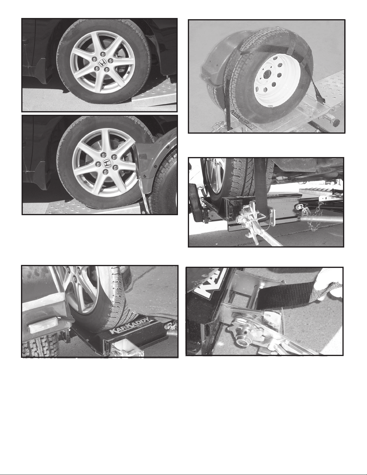
Step 6. With someone safely guiding you, slowly drive vehicle onto platform FRONT FORWARD. (Any vehicle mounted
on tow dolly must be mounted with front of the vehicle facing
forward.) Drive the car forward until the tires touch the ramps.
Make sure the tire is aligned to ascend onto the ramps.
Step 8. Place one tie-down strap over each tire and secure
hooks to rods located at the rear of each wheel platform. The
short side of the hook must face the rear of the Kar Kaddy.
Step 9. Be sure tie-down winch is centered with the tire
before tightening straps.
Step 7. Drive vehicle onto the platform - front forward - until
tires touch the wheel stops at the front of each side of the
platform and the platform tilts to a flat position. Make sure the
car is centered on the platform. Towed vehicle tires must fit in
wheel troughs without overhanging sides. Engage towed
vehicle parking brake. Shift loaded car into "park" and lock
steering wheel with front tires in a straight position. If the car
does not have a locking steering column the steering wheel
must be tied securely with front tires in a straight position.
Rear Wheel Drive: Disconnect towed vehicle driveshaft for
rear wheel drive vehicles with automatic transmission.
For manual transmission: Consult your vehicle owners
manual for towing suitability with the drive shaft connected.
Page 16
Step 10. Thread tie-down strap through the slotted tube on
the tie-down winch. Pull approx. 6" of strap through this slot.
Begin tightening strap making sure the tail becomes enclosed
by the strap coming over the tire. Tighten the straps ensuring
that the strap fed through the slot binds between the shaft and
the strap being wound onto the winch shaft. While tightening
straps, pull cross strap forward to ensure even tightening.
NOTE: Be sure to tighten straps until each tire starts to
flatten against tire stop. After each strap is tight, insert a
safety pin in each winch. Disengage towed vehicle parking
brake.
Straps must be retightened after first 5 miles of travel.
Check straps every 50 miles thereafter to ensure they are
tight and not rubbing or fraying.
Page 17
Step 11. Make sure the tie-down strap is the correct size for
the auto tire. See page 11 of this instruction for proper fit and
exchange instructions.
Step 12. Hook the towed vehicle safety chains to frame of
vehicle directly above the area where the chains are mounted
on the Kar Kaddy. Leave some slack in the chains to allow
suspension movement of the towed vehicle.
B
Step 14. To pull the Kar Kaddy empty, make sure "AutoSteer" LOCKING PIN IS IN PLACE and towing vehicle
safety chains are up and hooked. Tie-down winch handles
should be left in a down postion (horizontal) position with
safety pins in place when towing loaded or empty. DO NOT
ATTEMPT TO PULL KAR KADDY WITH WHEEL PLATFORM IN LOADING (tilted) POSITION.
DAMAGE PREVENTION
Check your vehicle manual or registration for vehicle weight.
Towing vehicle must be larger and at least 1,000 lbs. heavier
than the towed vehicle and tow dolly combined.
Do not pack goods in car that is being towed. Overloading
the Kar Kaddy or exceeding the width limit may result in
damage to both car and Kar Kaddy.
REAR WHEEL DRIVE PRECAUTIONS
Disconnect towed vehicle driveshaft for rear wheel drive
vehicles with automatic transmission. Simply placing transmission in neutral is not sufficient to prevent damage to
transmisssion.
For manual transmission: Consult your vehicle owners
manual for towing suitability with the drive shaft connected.
ALL VEHICLES MOUNTED ON THE KAR KADDY MUST BE
WITH THE FRONT OF THE VEHICLE FACING FORWARD.
A
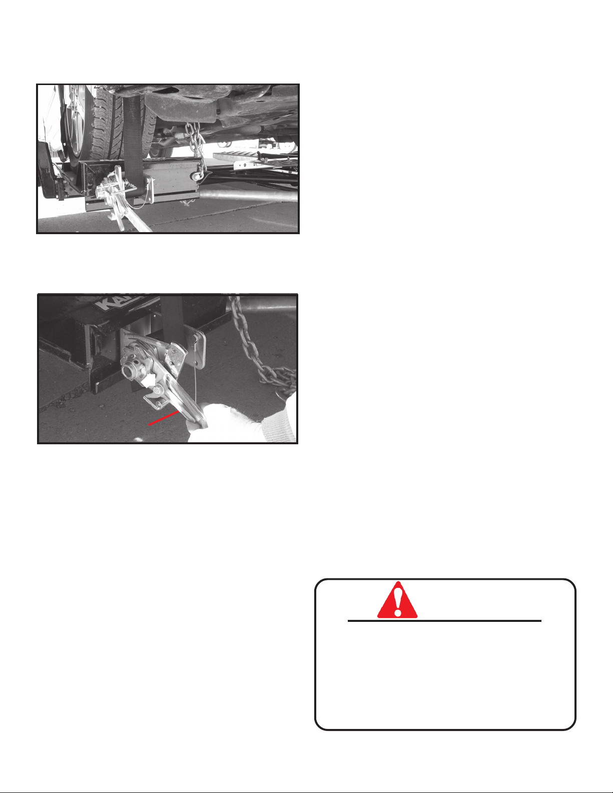
Step 13. TO UNLOAD towed vehicle. Make sure that plat-
form and vehicle are straight. Reinstall driveshaft. Ensure
that towed vehicle parking brake is fully engaged, then
unhook the towed vehicle safety chains, and release the tiedown straps. NOTE: Tie down straps must be "quick released" by grasping ratchet pawl (A) and ratchet handle (B)
simultaneously and pushing down sharply. This process will
permit easy removal of strap from winch.Swing the wheel
platform locking latch handle forward, towards the coupler.
This will allow the platform to tilt as you slowly drive off. Make
sure the winch ratchet handles are horizontal. Replace the
"Auto Steer" locking pin (for towing empty).
SAFETY
• Examine winches and straps to make sure they are in
good condition.
• Check wheel nuts every trip.
• Tires must be inflated to recommended pressure by
tire manufacturer.
• Be certain the safety lock pins lock the strap winches.
• Retighten the straps over the tires after the first 5 miles
of travel. Check straps every 50 miles therafter to
ensure they are tight and not rubbing or fraying.
Page 17
Page 18

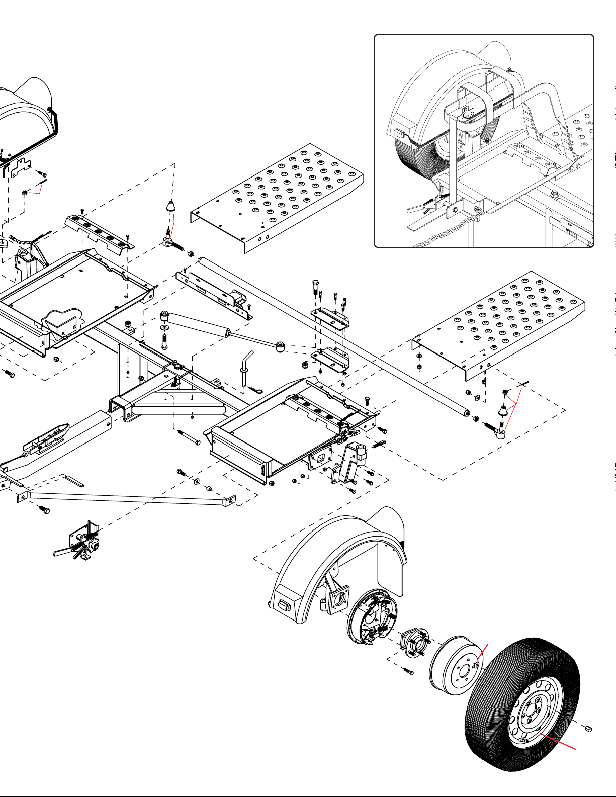
KK370SB PARTS BREAKDOWN
REF. PART
NO. NO. QTY. DESCRIPTION
1. 03528 2 Tie-down Strap assembly, Black
2. 5809 1 Right Fender Assembly with Lights
3. 5808 1 Left Fender Assembly with Lights
4. 04424-95 2 Fender Backing Plate
5. 00914 6 3/8”-16UNC x 1-1/2” Hex Head Bolt (gr.5)
6. 02592 18 3/8”-16UNC Nylon Lock Nut
7. 04165-81 1 Right Wheel Carrier
8. 04166-81 1 Left Wheel Carrier
9. 01732 4 1"I.D. x 1-1/4"O.D. x 1-1/2"lg. Bushing (brnz)
10. 11588 2 King Pin (1” x 6-1/2”)
11. 01731 4 1-1/4" Dust Cap
12. 05587 2 1" I.D.x 14 GA Narrow Rim Machine Washer
13. 11566-81 1 Right Drop Axle Mount
14. 11550-81 1 Left Drop Axle Mount
15. 11551 2 King Pin Retainer Bolt
16. 03724 2 7/16”-20UNF Center Punched Nut
17. 02377 8 7/16”-20UNF x 1-1/2” Epoxy Bolt (gr.8)
18. 04168 8 7/16”-20UNF Nylon Lock Nut
19. 02178 18 1/2”-13UNC Nylon Lock Nut
20. 02579-95 2 Pivot Bushing
21. 00085 15 1/2" Flatwasher
22. 01254 15 1/2"-13UNC x 1-1/2" Hex Head Bolt (gr.5)
23. 02747-96 2 Bracing Strut
24. 03503 2 5/8”-11UNC x 1-1/4” Epoxy Bolt (gr.5)
25. 02434 1 5/8”-13UNC x 4-1/2” Hex Head Bolt (gr.5)
26. 02587 4 5/8”-13UNC Nylon Lock Nut
27. 02696 2 5/8"-11UNC x 2-3/4" lg. Hex Head Bolt (gr.5)
28. 00477 1 5/8" Flatwasher
29. 01729-35 1 Steering Stabilizer Shock
30. 11553-81 1 Tie Rod Clamp, Bottom
31. 11554-81 1 Tie Rod Clamp, Top
32. 00907 12 3/8”-16UNC x 1” Hex Head Bolt (gr.5)
33. 02494 2 3/8”-16UNC x 2-1/4” Hex Head Bolt (gr.5)
34. 00967 8 1/2"-13UNC x 1-1/4" Hex Head Bolt (gr.5)
35. 04772-96 2 Ramp
36. 01718-95 1 Tie Rod Locking Pin
- 02189 1 Replacement Black Handle Grip for Locking Pin
37. 00182 1 Hair pin
38. 11933-81 1 KK370SB Main Frame
39. 5806 1 License Plate Bracket Assembly
40. 04771-81 1 Tie Rod
41. 5179 1 Right Tie Rod End w\Right Hand Threads
42. 5178 1 Left Side Tie Rod End with Left Hand Threads
43. 01905 1 9/16"-18UNF Jam Nut w/Right Hand Threads
44. 01904 1 9/16"-18UNF Jam Nut w/Left Hand Threads
45. 04773-96 2 Rear tire Stop
46. 00523 4 3/8"-16UNC x 1-1/4" lg. Hex Head Bolt (gr.5)
47. 02243 1 Black Vinyl Hand Grip
48. 07077-81 1 Tongue
49. 09417 1 DA91 Actuator (less coupler)
50. 5433 1 Right Winch assembly
51. 5432 1 Left Winch Assembly
52. 02772 2 1/4”-20UNC Nylon Lock Nut
53. 04176 2 1/4”-20UNC x 3/4" Carriage Bolt
54. SB24428 1 10” Brake Cluster, RH
- SB24429 1 10” Brake Cluster, LH
55.
SB40929-30 2 10” Brake Drum
56. 01898 4 7/16”-14UNC x 1-1/4” Hex Head Bolt (gr.5)
57. 00078 2 7/16" Lockwasher
58. 00059 8 3/8” Flat Washer
59. 02771 2 7/16”-14UNC Nylon Lock Nut
60. 02383 4 36” Safety Chain
61. 04017-95 1 Bolt on Handle
62. 02189 1 Rubber Handle Grip
63. 01338 1 1/2"-12UNC x 4-1/2" lg. Hex Head Bolt (gr.5)
64. 01975 2 1/2"-12UNC x 5" lg. Hex Head Bolt (gr.5)
65. 04174 4 Retainer Washer
66. 04369 2 Hub and Spindle
- 02917 - Replacement 12mm x 1.50mm Stud Bolt
67. 02210 8 7/16”-20UNF x 1-1/4” Epoxy Bolt (gr.8)
REF. PART
NO. NO. QTY. DESCRIPTION
68. 04826 2 ST205/75R14 "C"Range Radial Tire
69. 09296 2 Rim, 14 x 5.5, 5 on 115mm B.C.
70. 02933 10 Chrome Lug Nut
71. 04167 6 7/16”- 20UNF x 1” hex head bolt (gr.8)
72. 04168 6 7/16”-20UNF Nylon Lock Nut
73. 12445-30 1 Spring Return System
Please order replacement parts by PART NO. and DESCRIPTION.
60
50
21
19
19
49
21
6
59
73
58
56
60
Page 18
56
57
61
64
58
24
63
7
11
62
6
10
2
9
1
20
21
23
Page 19
1
4
5
35
41
13
2
19
22
46
47
48
45
46
26
23
26
52
28
22
27
53
41
25
21
43
39
29
38
52
20
40
36
53
37
19
26
18
27
6
16
14
33
6
32
31
30
17
71
15
34
6
58
35
19
44
21
72
42
24
51
Page 19
54
3
8
67
66
55
65
68
70
69
Page 20
13
WINCH ASSEMBLY
REF. PART
Left Winch Shown
21
18
8
20
19
14
17
16
15
10
11
12
9
2
4
7
5
6
Left Winch Shown
18
10
3
3
1
NO. NO. QTY. DESCRIPTION
5432 1 Left Ratchet Winch Assembly (Plated)
5433 1 Right Ratchet Winch Assembly (Plated)
1. 03569-95 1 Ratchet Frame
2. 03570-95 1 Left Spool Tube
- 03571-95 1 Right Spool Tube
3. 03577 2 Heavy Duty External Snap Ring
4. 03574-95 1 Ratchet Handle
5. 03668 1 18 Ga. Shim Washer
6. 03575-95 1 Left Ratchet Gear
- 03576-95 1 Right Ratchet Gear
7. 03666 1 5/16" x 1-1/4" Roll Pin
8. 02243 1 Black Vinyl Hand Grip
9. 05450 1 Winch Pawl
10. 01864 2 Winch Pawl Spring SS
11. 05449 1 Winch Pawl Bushing SS
12. 00004 1 5/16”" Flatwasher
13. 05444 1 3/8"-16 UNC x 3/4" Hex Bolt w/epoxy Gr.5
14. 03572-95 1 Left Ratchet Pawl Arm
- 03573-95 1 Right Ratchet Pawl Arm
15. 03578 1 5/16"-18 UNC x 1/2" Shoulder Screw
16. 01998 1 5/16" Flatwasher SS
17. 02002 1 1/4" Flatwasher SS
18. 02772 2 1/4"-20 UNC Nylon Locknut
19. 04055 1 1/4"-20 UNC x 1" Hex Hd. Bolt Gr.5
20. 00214 1 1/4" Flatwasher
21. 05337 1 Lock Pin w/Cable
Please order replacement parts by PART NO. and DESCRIPTION.
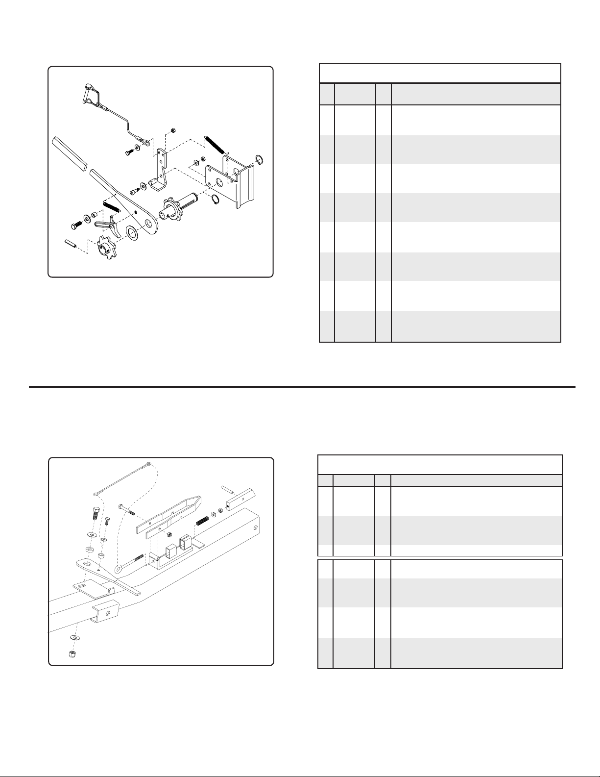
TILT-BED LATCH ASSEMBLY
REF. PART
NO. NO. QTY. DESCRIPTION
5511 - Tilt-Bed Latch Kit
1*. 03434 1 5/16"-18 UNC x 4" Eye Bolt
2*. 04221 1 5/16"-18 UNC x 2-1/2 Hex Head Bolt (Gr 5)
3*. 00004 1 5/16" Flatwasher
4*. 00007 1 5/16"-18 UNC Hex Nut
5*. 03379-95 1 Latch Block
6*. 03435 1 Roll Pin (5/16" x 2-1/4")
7*. 03499 1 Latch Spring - Stainless Steel
8. 03382-95 1 Latch Handle Pivot Bushing
9. 03574-95 1 Latch Handle
10. 03381-95 1 Latch Catch
11. 03433 1 Latch Cable
12. 02802 1 5/16-18 UNC Nylon Insert Locknut
13. 00967 8 1/2"-13UNC x 1-1/4" lg. Hex Head Bolt (gr.5)
14. 00085 1 1/2" Flatwasher
15. 00059 9 3/8" Flat Washer
16. 02178 13 1/2"-13UNC Nylon Insert Locknut
17. 05449 1 Spacer Bushing - Stainless Steel
18. 05444 1 3/8"-16 UNC x 3/4" Epoxied Hex Bolt (Gr 5)
Please order replacement parts by PART NO. and DESCRIPTION.
* Items included in 5511 kit
14
11
2
13
18
10
7
12
15
8
17
1
6
5
4
3
9
KIT #5511
TILT-BED LATCH
14
ASSEMBLY
16
Page 20
Page 21
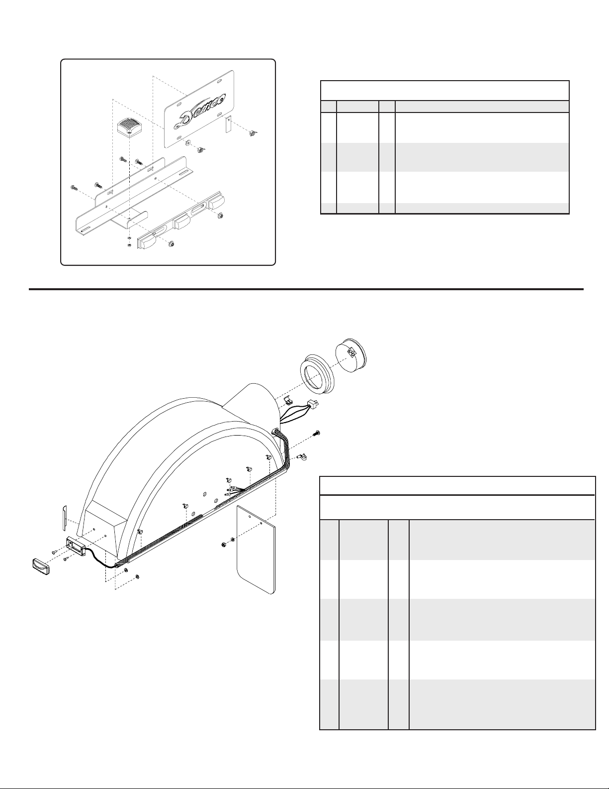
LICENSE PLATE BRACKET ASSEMBLY
REF. PART
NO. NO. QTY. DESCRIPTION
4
5
3
2
2
3
8
6
1
9
6
7
Please order replacement parts by PART NO. and DESCRIPTION.
5806 - License Plate Bracket and Light Assembly
1. 04505-95 1 License Plate and Light Cluster Bracket
2. 04176 2 1/4”-20UNC X 3/4” Carriage Bolt
3. 02214 2 #10 NC X 1/2” Slotted Truss Head Screw
4. 02163 1 Square License Plate Light w/Washer and Nut
- 02164 - Clear License Plate Light Lens Only
5. 02580-95 1 License Plate Clip
6. 02770 2 1/4”-20UNC Nylon Insert Wing Nut
7. 01077 2 1/4” NC Serrated Lock Nut
8. 00214 1 1/4”-20UNC Flat Washer
9. 04513 1 3 Cluster Light Bar
4
4
7
FENDER ASSEMBLY
11
14
6
7
1
8
9
18
2
2
2
12
2
2
3
10
4
13
15
19
17
16
5
PARTS LIST
REF.
NO. PART NO. QTY. DESCRIPTION
5808 - Left Fender Assembly
5809 - Right Fender Assembly
1. 01883 2 Wire Splicer
2. 04425 5 Tinnerman U-clamp
3. 04515 1 17-1/2” Wire Loom
4. 04643 2 9/16” x 5/8” Pop Rivet
5. 05443 1 Nylon Cable Hanger
6. 05447 1 4” Light Grommet
7. 07081 1 Tail Light Wire Harness
8. 05446 1 4” Round Tail Light
9. 12010 1 Left Fender Assembly
- 12011 1 Right Fender Assembly
10. 11973 1 Black Marker Base Mount
11. 11975 1 Yellow Marker Light
12. 11619 1 12” Wire Loom
13. 11974 1 Front Marker Wiring Harness
14. 04508 1 Amber Reflector
- 04804 1 Red Reflector
15. 07490 2 3/16” Washer
16. 01769 1 Kar Kaddy Mud Flap
17. 02772 2 1/4” Nylon Lock Nut
18. 05338 2 1/4” Slotted Truss Head Bolt
19. 00214 2 1/4” Flat Washer
Page 21
Please order replacement parts by PART NO. and DESCRIPTION.
Page 22

DEMCO PRODUCTS - KAR KADDY
ORIGINAL PURCHASER’S LIMITED WARRANTY
1. Extent and Duration of this Warranty:
Your Demco Kar Kaddy is warranted to be free from defects in
materials and workmanship under normal use and service for a
period of one year after date of purchase by the original (first)
retail owner, or until it is resold or transferred by the original
owner. Hubs used on the KK370SB are warranted for a period
of three years after the date of purchase by the original (first) retail
owner or until it’s resold or transferred by the original owner. Tires
and lights are not included in this warranty.
Tires are warranted by the manufacturer against defects in
materials and workmanship, but not against road hazards.
necessary by normal use of parts, accessories or other equipment which in the judgment of Warrantor, are either incompatible with the Demco Kar Kaddy, or affect its operation, performance or durability.
This warranty does not cover:
1) normal wear and tear
2) road film or gravel damage to paint
3) paint
4) rust damage
5) Any Demco Kar Kaddy that has been loaded in excess of the
load capacity stated on the tow dolly identification label.
Any part of the Demco Kar Kaddy, except tires and lights, found,
in the judgement of the manufacturer to be defective in materials
or workmanship will be repaired or replaced at the manufacturer’s
option without charge for parts or labor to the original owner.
2. Manufacturer and Warrantor of Tow Dolly:
Dethmers Manufacturing Co.
4010 320th Street
P.O. Box 189
Boyden, IA 51234
(712) 725-2311
The manufacturer and warrantor of the tires has his name
molded into the tires. Tire warranty questions and claims can be
taken directly to an authorized dealer of the tire manufacturer.
3. Repair or Replacement Procedure:
If your Demco Kar Kaddy develops a defect (except for tires or
lights) during the warranty period, promptly notify Dethmers
Manufacturing Co. customer service department. Until such
notice is received, Warrantor will not be responsible for any repair
or replacement.
Upon receipt of notice from you, Warrantor will have a choice of
options in replacing any part it determines to be defective:
a) Warrantor may require you at your own expense to deliver
or ship the part to its factory or authorized dealer. Any
defective part will be repaired or replaced and returned to
you free of charge. Any part returned to Warrantor and
found not to be defective will be returned to you freight
collect with an explanation.
b) Warrantor may elect to ship a new part to its dealer to be
exchanged free of charge for the defective part returned
by you to the dealer.
c) Warrantor may elect to ship or deliver a replacement part
to your address.
Warranty claims on tires should be presented to a local authorized dealer of the tire manufacturer. Provide proof of purchase
when making a tire warranty claim.
Warrantor has a policy of continuous product improvement. We
reserve the right to change or improve the design of any Demco
Kar Kaddy model, including but not limited to state of the art
changes, without assuming any obligation to modify any tow
dolly previously manufactured.
Warrantor assumes no responsibility to the owner for loss of
use of the tow dolly, loss of time, inconvenience or other
damage consequential or otherwise, including, but not limited
to expense for gasoline, expense of transporting the tow dolly
to the dealer and expense of returning the tow dolly, mechanic’s
travel time, telephone or telegram charges, road service/towing
charges, rental of another tow dolly during the time warranty
repairs are being performed, travel, lodging, loss or damage to
personal property or loss of revenue or earnings.
5. Limitations of Implied Warranties:
All implied warranties, if any, expire and terminate upon expiration of this warranty. Some states do not allow limitation on how
long an implied warranty lasts, so this limitation may not apply
to you.
6. Limitation of Consequential Damages:
Warrantor’s responsibility under this warranty extends solely to
repair or replacement of your Demco Kar Kaddy and its component parts.
Warrantor does not assume responsibility for, nor shall it be
liable for, any special, incidental or consequential damages.
Some states do not allow the exclusion or limitation on incidental or consequential damages, so the above exclusion or
limitation may not apply to you.
7. Use of Vehicle Identification Number (VIN):
The VIN is a 17 digit number located in the lower left corner of
the tow dolly identification label. The label is located on the left
side of the tow dolly frame. Be sure to include the VIN number
in all communications with Warrantor or its dealers concerning
the warranty.
8. Purchaser’s Rights:
This warranty gives you specific legal rights, and you may also
have other rights which vary from
4. Limitations on Warranty Coverage:
Coverage under this warranty will be effective only when a copy
of the original invoice, showing the date and location of purchase,
accompanies any claim for warranty.
Warrantor has no liability whatsoever and this warranty is null and
void if any Demco Kar Kaddy has been misassembled or subjected
to neglect, negligence, misuse, accident or operated in any way
contrary to the operating and maintenance instructions as specified
in the Demco Owner’s Manual for that model tow dolly.
This warranty does not cover any tow dolly that has been altered
or modified so as to affect the tow dolly’s operation, performance
or durability, or that has been modified to change the intended
use of the tow dolly.
In addition, the warranty does not extend to repairs made
Page 22
Page 23
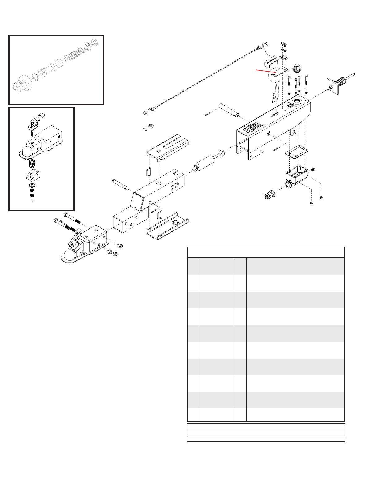
MODEL DA91 ACTUATOR PARTS BREAKDOWN
8
23
**12
**10
13
8
14
17
14
18
5398 Master Cylinder Repair Kit
(gasket included)
11
not included
28
4
5495
Coupler Repair Kit
2
9
2
1
3
2” Lever Lock Coupler
RATED AT 6000#
BLEEDING THE SYSTEM
The first requirement for safe, sure hydraulic braking is the use
of quality brake fluid. Use only DOT-3 or DOT-4 brake fluid
from a sealed container.
If pressure bleeding equipment is available, follow the
manufacturer’s instruction in bleeding the system.
If system must be bled manually, proceed as follows: Fill
master cylinder with fluid. Install bleeder hose on first wheel
cylinder to be bled.
Have loose end of hose submerged in brake fluid in glass
container to observe bubbling.
By loosening the bleeder screw located in the wheel cylinder
one turn, the system is open to the atmosphere through the
passage drilled in the screw. Pump actuator with long steady
strokes. The bleeding operation is completed when bubbles
no longer rise to the surface of the fluid. Be sure to close
bleeder screw securely.
Repeat bleeding operation at each wheel cylinder. During the
bleeding process, replenish the brake fluid, so the level does
not fall below the 1/2 full level in the master cylinder reservoir.
After bleeding is complete, make sure master cylinder reservoir is filled and filler cap is securely in place.
After the bleeding operation has been completed, apply pressure to the system and check the whole brake system for leaks.
28
27
**16
15
15
25
9
26
6
7
9
20
22
21
5
24
19
Model 91 ACTUATOR 8669111 PARTS LIST
REF.
NO. PART NO. QTY. DESCRIPTION
1. 09417 1 6000# 2" Lever Lock Coupler (zinc plated)
2. 01896 3 1/2"-13UNC x 4" Hex Head Bolt (gr.5)
3. 02178 3 1/2"-13UNC Nylon Insert Lock Nut
4. 05426 1 Front Shock Pin (drop tube actuators)
5. 11079-95 1 Drop Tube Actuator Slider (plated)
6. SB12426 1 Damper/ Shock
7. 11164-95 1 3 Bolt Mount Outer Case (plated)
8. 05424 2 5/16" External Tooth Lock Washer
9. 02363 2 5/32" x 1 1/4 Cotter Pin(Qty 3 w/drop tube)
**10. 05408 1 3/32" Cable with hooks
11. SB10555 - Replacement S-Hooks ONLY
**12. 05693-95 1 Emergency Lever Spring (plated)
13. 05961 2 5/16"-18UNC x 5/8" Hex Head Bolt (gr.5)
14. 00618 4 1/4-20UNC x 2" Hex Head Bolt (gr.5)
15. 00057 4 1/4" Lock Washer
**16. 05951 1 Emergency Lever Assembly
17. 03876 1 Master Cylinder Cap w/ Diaphragm & O-ring
- 05849 1 O-Ring Only (not shown)
18. 05977 1 Push Rod Assembly
19. 00062 4 1/4”-20 UNC Hex Nut
20. 09153 - Plastic Master Cyl. Gasket ONLY
21. 10616 1 Master Cylinder
22. SB12098 1 .018 Connector Orifice (Drum Brakes)
23. 03866-95 1 Lever Guide (plated)
24. 05687 1 Master Cylinder Protective Boot
25. 05986-95 1 Connecting Pin (plated)
26. 10965 1 Upper Slider
27. 10966 1 Lower Slider
28. 10967 2 Side Spacers
- 5401 - Lever Replacement Kit (incl. items w/**)
- 5650 - Master Cyl. Replacement Kit (drum)
- 5495 - Coupler Repair Kit
Please order replacement parts by PART NO. and DESCRIPTION
19
Page 23
Page 24
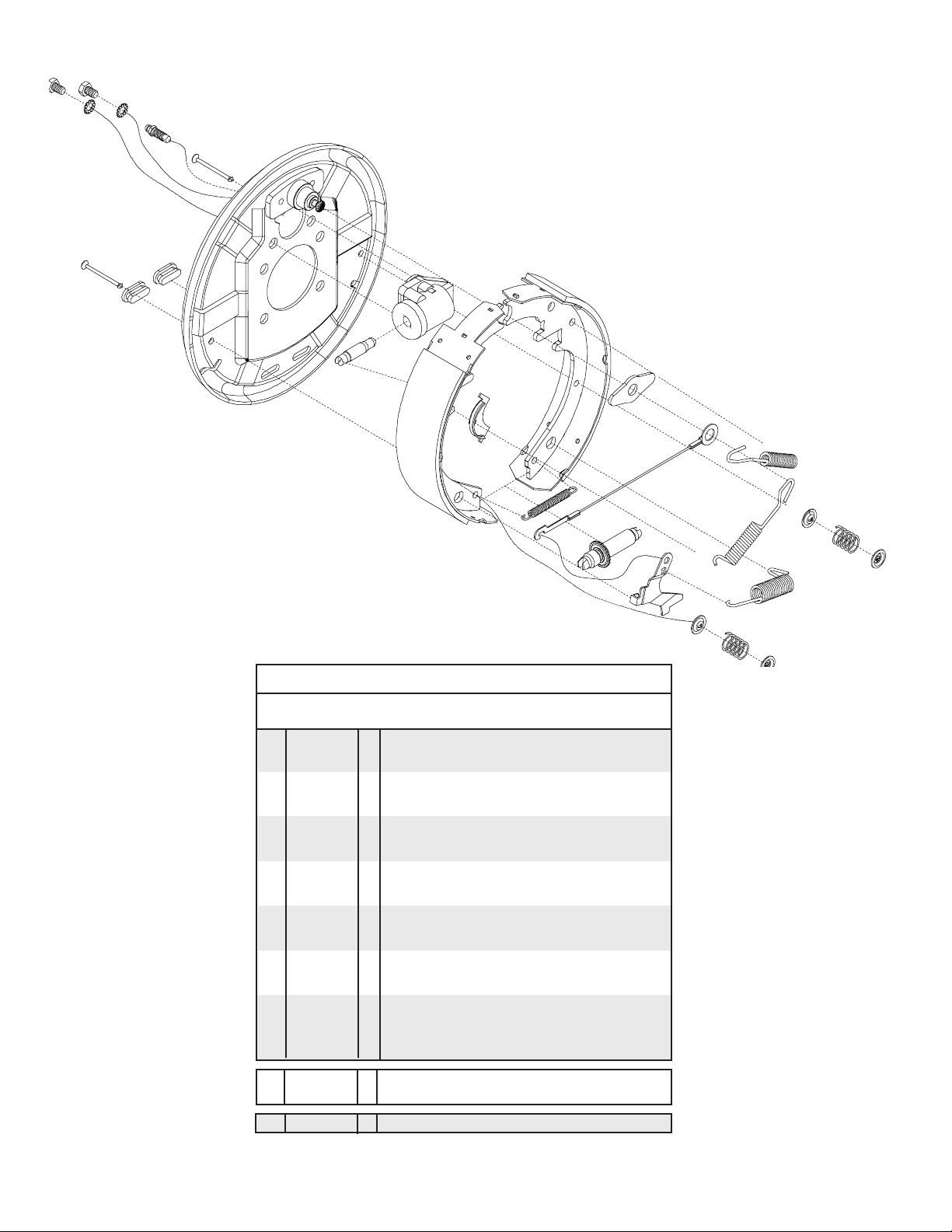
10" SELF-ADJUSTING BRAKE CLUSTER and DRUM PARTS BREAKDOWN
4
5
5
7
16
1
4
16
2
6
3
2
8
11
13
10
3
12
19
9
10
17
18
15
17
BRAKE CLUSTER PARTS LIST
REF. PART
NO. NO. QTY. DESCRIPTION
- SB24429 - Left Hand Cluster (shown above)
- SB24428 - Right Hand Cluster
1. SB23871-80 1 Back Plate Assembly - (NDH Hub Mounting)
2. SB9254 2 Cover Plate - Adjusting Hole
3. SB10954 1 Brake Shoe Kit (includes 2 Primary & 2 Secondary)
4. 04305 2 5/16"-18UNC-Gr5 x 1/2" Hex Hd Bolt
5. 05424 2 5/16" External Tooth Washer
6. SB9776 1 Wheel Cylinder Assembly - Right
- SB9777 1 Wheel Cylinder Assembly - Left
7. 05431 1 Bleeder - replacement
8. SB9783 1 Push Rod
9. SB24047 1 Adjusting Screw Assembly - "R" (for LEFT cluster)
- SB24048 1 Adjusting Screw Assembly - "L" (for RIGHT cluster)
10. SB10958 2 Spring - Shoe
11. SB10961-95 1 Shoe Guide
12. SB23937 1 Cable
13. SB23936 1 Cable Guide
14. SB23724 1 Spring - Adjusting Screw
15. 05415-95 1 Lever - Right
- 05414-95 1 Lever - Left
16. SB10959 2 Pin - Shoe Hold Down
17. SB9789 4 Cup Shoe Hold Down
18. 05983 2 Spring - Shoe Hold Down
19. 03380 1 Spring
17
18
14
17
- SB15845 1 Wheel Cylinder Repair Kit
- SB40929-30 2 10" Brake Drum
Please order replacement parts by PART NO. and DESCRIPTION.
Brake shoe kit can be ordered for one complete axle only.
(includes spring, cup and boot)
Page 24
Page 25
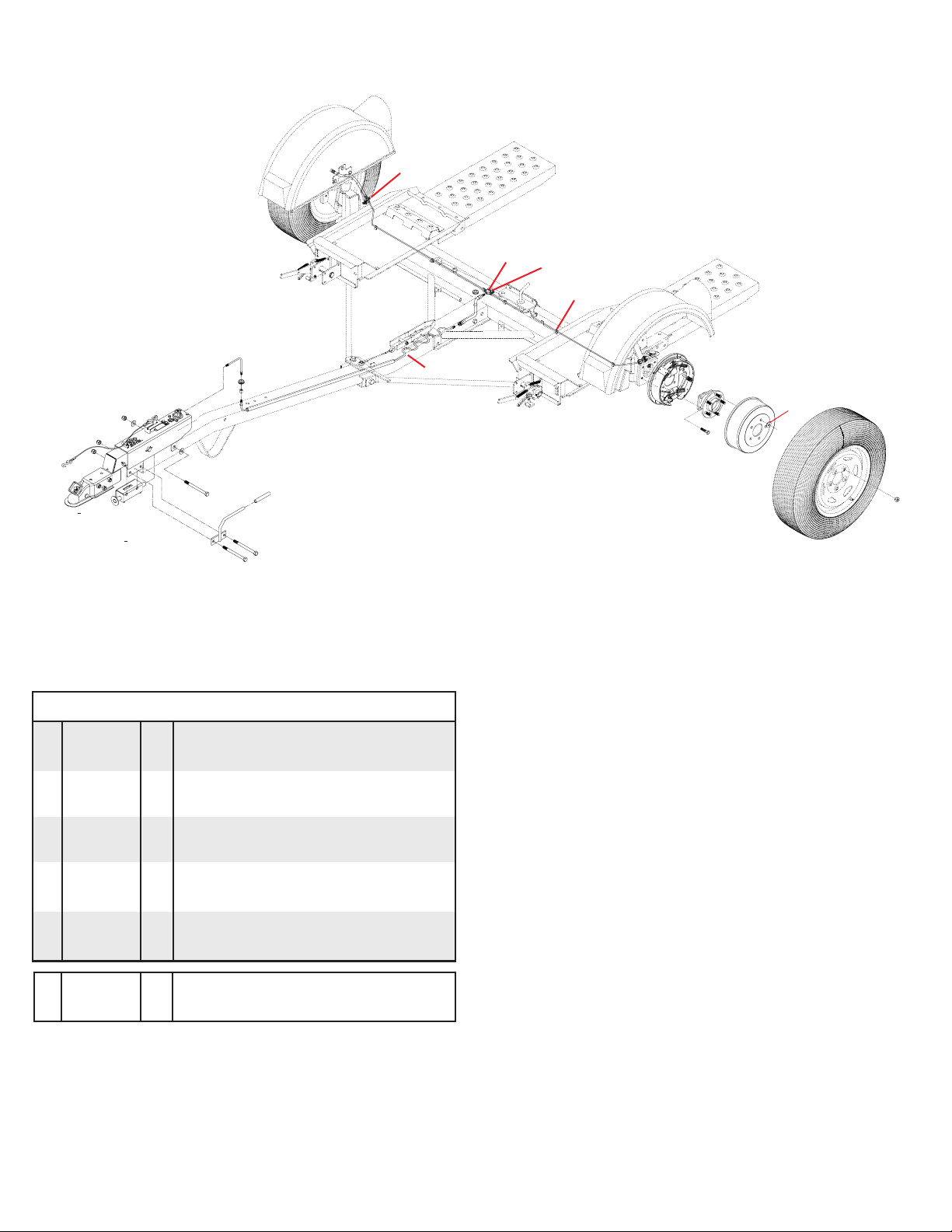
SURGE BRAKES PARTS BREAKDOWN
Model DA91
Brake Actuator
15
10
13
7
6
5
12
14
2
11
4
5
2
3
1
7
16
9
8
17
SURGE BRAKES PARTS LIST
REF. PART
NO. NO. QTY. DESCRIPTION
1. SB566 1 66" Brake Line
2. 01863 2 Rubber Gommet
3. 02746 1 54" Protective Hose
4. SB7H67 1 7" Brake Hose (rubber)
5. SB541 2 41" Brake Line
6. SB7764 2 Rubber Brake Line Clip
7.
02032
8. 02210 8 7/16"-20UNF x 1-1/4" Epoxied Bolt (gr.8)
9. 04174 4 12mm Retainer Washer (2 per drum)
10. SB5045 1 4-1/2” Brake Line
11. 02549 4 Rubber Protector
12. SB7785 1 3/16” Brake Line Tee
13. SBD10 1 Union Fitting
14. 05960 1 5/16” x 1/2” Self-Threading Bolt
15. 12445-30 1 Spring Return System
16. SB24429 - Left Brake Cluster
-- SB24428 - Right Brake Cluster
17. SB40929-30 - 10” Brake Drum
Please order replacement parts by PART NO. and DESCRIPTION.
2 12" Brake Hose (rubber)
BLEEDING THE SYSTEM
The first requirement for safe, sure hydraulic braking is the use
of quality brake fluid. Use only DOT-3 or DOT-4 brake fluid
from a sealed container.
If pressure bleeding equipment is available, follow the
manufacturer’s instruction in bleeding the system.
If system must be bled manually, proceed as follows: Fill
master cylinder with fluid. Install bleeder hose on first wheel
cylinder to be bled.
Have loose end of hose submerged in brake fluid in glass
container to observe bubbling.
By loosening the bleeder screw located in the wheel cylinder
one turn, the system is open to the atmosphere through the
passage drilled in the screw. Pump actuator with long steady
strokes. The bleeding operation is completed when bubbles
no longer rise to the surface of the fluid. Be sure to close
bleeder screw securely.
Repeat bleeding operation at each wheel cylinder. During the
bleeding process, replenish the brake fluid, so the level does
not fall below the 1/2 full level in the master cylinder reservoir.
After bleeding is complete, make sure master cylinder reservoir is filled and filler cap is securely in place.
After the bleeding operation has been completed, apply pressure to the system and check the whole brake system for leaks.
Page 25
Page 26

Wiring Diagram
1
2
PARTS LIST
REF.
NO. PART NO. QTY. DESCRIPTION
1. 11590 1 Tongue Wiring Harness
2. 11591 1 Main Frame Wiring Harness
Please order replacement parts by PART NO. and DESCRIPTION.
TESTING LIGHTS BEFORE USE
1. Check that the WHITE (ground) wire of the wiring harness
is connected to the Kar Kaddy frame and the WHITE
(ground) wire is connected to the frame of the towing
vehicle.
2. With headlights in "ON" position, the tail lights, the light
cluster bar, the license plate light, and the clearance lights
should be lighted.
3. Start engine and have someone depress brake pedal.
Brake lights of tow dolly and towing vehicle should come
"on" and "off" simultaneously with each application.
4. Turn left turn signal on. Left turn light of Kar Kaddy and
towing vehicle should flash simultaneously. Should the
turn signal lights of the trailer function opposite to those of
the towing vehicle, it is probable that the YELLOW (Driver
side) and GREEN (Passenger side) wires have been
reversed. Check the plug connection under the tongue of
the Kar Kaddy to make sure wire colors are not crossed at
that point. If plug connection is incorrect, correct problem
by reversing yellow and green wire connection on the
towing vehicle.
COLOR CODE FOR WIRING HARNESS
WHITE Ground
BROWN Tail Lights, License Plate Lights,
Light Cluster Bar & Clearance Lights
YELLOW Left Turn and Stop
GREEN Right Turn and Stop
WIRING OF THE TOWING VEHICLE
Connect wiring to towing vehicle, keeping in mind the color
code indicated below.
1. Make certain towing vehicle lights are "OFF".
2. Connect YELLOW wire to left turn signal and stop wire in
the left rear of towing vehicle with the wire splicer (01883)
supplied.
3. Connect GREEN wire to the right turn signal and stop
wire.
4. Connect BROWN wire to tail light wire.
5. VERY IMPORTANT - connect WHITE wire to frame body
of towing vehicle. This is the common ground, and a clean
metal - to - metal contact must be made.
CAUTION: Many flashers for vehicle turn signals will not
carry the additional load of Kar Kaddy turn signals. If
normal operation does not occur when connected to the
Kar Kaddy, a heavy duty replacement flasher may be
obtained through auto parts outlets.
Page 26
Page 27

KAR-KADD Y TOE-IN ADJUSTMENT
FRONT MEASUREMENT
(1/32" to 1/16" less than back measurement)
BACK MEASUREMENT
LOCKING
CLAMP
12"
18"
Ground
MEASURING THE TOE-IN
Have the tongue in a "hooked-up” position with the ball
coupler 18" off the ground. Jack up the axle just enough to
allow you to take the wheels off and put blocks under the axle.
Take the wheels off.
Find two 24" long bars, these could be a level, a square
or a straight piece of iron bar. Clamp one bar tight to the face
of each hub with 12" extending forward and backward of the
center of the spindle. The bars must be parallel to the platform
the car sits on. Measure across the back end of the bars and
then across the front end. The front measurement should be
1/32" to 1/16" less than the back measurement. If the unit
needs to be adjusted, this must be done by adjusting the tie
rod.
12"
C
L
TOE-IN ADJUSTMENT
1.
Put a mark on each side of the locking clamp on the tie rod.
2. Loosen the locking nuts on each end of the tie rod and
then the six bolts on the tie rod locking clamp.
3. Turn the tie rod whichever direction is needed until you
have a front measurement of 1/32" to 1/16" less than the
back measurement.
4. Hold the tie rod and tighten the locknuts on each end.
5. Measure again to make sure the toe-in measurement has
not moved.
6. Tighten the locking clamp bolts while holding clamp
between the marks you previously put on the tie rod.
7. Reassemble the rest of the Kar Kaddy unit.
Page 27
Page 28

OPTIONAL WHEEL JACK
WHEEL JACK PARTS LIST
- KK2WJ 1 Optional Wheel Jack w/ hardware
Please order replacement parts by PART NO. and DESCRIPTION.
* All options may not mount on tow dolly simultaneously.*
OPTIONAL DEFLECTOR PARTS BREAKDOWN
REF. PART
NO. NO. QTY. DESCRIPTION
5762 Optional Deflector
1. 02055-30 2 Deflector Framework
2. 02592 4 3/8"-16UNC Nylon Insert Lock Nut
3. 02759 2 3/8"-16UNC Square U-Bolt (fits around 3" tube)
4. 00161-95 2 Lock Handle
5. 02054-30 1 Deflector Slide Mount
6. 00095 4 3/8"-16UNC x 3/4" lg. Square Head Set Screw
7. 02743-30 1 Deflector Upright Post
8. 02165 1 Deflector Lacing Cord (1/8" x 25 ft.)
9. 11710 1 Deflector Fabric
Please order replacement parts by PART NO. and DESCRIPTION.
OPTIONAL LIGHT BAR (KKLB) PARTS BREAKDOWN
1
OPTIONAL DEFLECTOR PARTS LIST
REF. PART
NO. NO. QTY. DESCRIPTION
KKLB Kar Kaddy Light Bar (complete)
1. 01772 2 Nylon Security Strap with hooks & tightener
2. 01857 1 Left Tail/ Brake and Signal Light w/Lenses
3. 01773 1 Brown Jumper Wire
4. 01886 4 Wire Holder (metal)
5. 02385-30 1 Light Bar Framework
6. 02386-30 2 Adjustable Light Bracket
7. 01856 1 Right Tail/ Brake and Signal Light w/Lenses
8. 02772 10 1/4"-20UNC Nylon Insert Locknut
9. 00092 6 1/4"-20UNC x 1/2" Hex Head Bolt
10. 01777-30 2 Light Bar "Z" Bracket
11. 01778 4 3" Suction Cup w/Bolt (#13)
12. 02198 1 Light Bar Wiring Harness (new style)
13. 00068 4 1/4"-20UNC x 3/4" Hex Head Bolt
14. 01911 - Large Red Lens
15. 01912 - Small Red Lens
16. 01890 - Clear Lens
Please order replacement parts by PART NO. and DESCRIPTION.
LIGHT BAR PARTS LIST
Page 28
8
6
8
9
9
1
4
9
7
2
8
9
8
12
6
4
5
4
3
7
2
8
3
5
4
9
11
1
13
10
11
16
13
COLOR CODE FOR WIRING HARNESS
WHITE Ground
BROWN Tail Lights, License Plate Lights,
Light Cluster Bar & Clearance Lights
YELLOW Left Turn and Stop
GREEN Right Turn and Stop
1
14
15
1
Page 29

Ag ❍
Warranty Registration
RV ❍
Rental ❍
Dethmers Manufacturing Company
4010 320th Street • Box 189 • Boyden, Iowa 51234
Toll Free 800-54DEMCO (800-543-3626) • FAX 800-845-6420
www.demco-products.com
Very
Satisfied
Satisfied
Dissatisfied
How satisfied are you with our product? ❍❍❍❍
How satisfied are you with the dealership/distributor sales staff? ❍❍❍❍
Dealer/Distributor Name
City State
How satisfied are you with the company sales staff? ❍❍❍❍
How satisfied are you with the delivery? ❍❍❍❍
Did you have any contact with a Demco Representative? YES NO
If YES, how satisfied were you? ❍❍❍❍
I would recommend this product to my family and friends. YES NO
Brakes ❍
Marine ❍
Very
Dissatisfied
Would you purchase again from DEMCO? YES NO
Since taking delivery, have you been contacted by the dealer? YES NO
Did you have any problems with this DEMCO product? YES NO
If YES, are you satisfied with the company’s resolution of your problem? ❍❍❍❍
Why did you purchase this product?
Please list the specific source of information prompting this purchase.
After purchasing this product, do you see any needed product improvement? If yes, what improvement?
What other products would you like to see DEMCO offer?
Comments
Owner’s Name: Mailing Address:
City: State: Zip Code:
Model#:
Serial #:
Purchase Date:
Owner’s Signature:
Please return to DETHMERS MFG. CO. By FAX or tri-folding this form to the backside, it is pre-addressed.
Page 29
Page 30

Dethmers Manufacturing Company
4010 320th Street, Box 189
Boyden, Iowa 51234
Postage
Page 30
Page 31
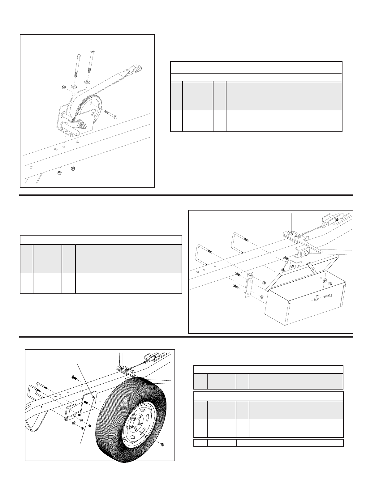
OPTIONAL WINCH
5
PARTS LIST
REF.
6
7
1
7
4
3
NO. PART NO. QTY. DESCRIPTION
KK2W 1 Optional Winch
1. 04620 1 Winch Mechanism (1400 capacity)
- 04621 - Replacement Handle
3. 01738 1 Strap Assembly (includes strap & hook)
4. 02207 1 3/8"-16UNC x 3" Hex Hd. Bolt (gr.5)
5. 02769 2 3/8"-16UNC x 4" Hex Head Bolt (gr.5)
6. 00059 2 3/8" Flatwasher
7. 02592 3 3/8"-16UNC Nylon Insert Locknut
Please order replacement parts by PART NO. and DESCRIPTION.
* All options may not mount on tow dolly simultaneously.*
OPTIONAL TOOL BO X
PARTS LIST
RKTB 1 Optional Tool Box
1. 00059 4 3/8" Flatwasher
2. 02592 8 3/8"-16UNC Nylon Insert Locknut
3. 01888-30 1 Tool Box
4. 00182 1 Small Hair Pin
5. 02742-30 2 Mounting "Z" Bracket
6. 00907 4 3/8"-16UNC x 1" Hex Head Bolt (gr.5)
7. 02759 2 3/8"-16UNC x 3" Square U-Bolt
Please order replacement parts by PART NO. and DESCRIPTION.
* All options may not mount on tow dolly simultaneously.*
OPTIONAL SPARE TIRE and MOUNT PARTS BREAKDOWN
Drive in stud here for
tire with rim #04173
(100mm bolt circle).
6
4
7
7
2
6
5
- RK4ST 1 Optional Spare Tire and Rim
1. N/A 1 ST205/75R 14"x"C" BSW Radial Tire
2. 09296 1 6" x 14" Rim 115mm Bolt Circle
1
4
3
2
3
7
Drive in stud here for
tire with rim #04366
(115mm bolt circle).
8
2
1
5
* All options may not mount on tow dolly simultaneously.*
RKSTM 1 Spare Tire Mounting Bracket
3. 02193-30 1 Spare Tire Bracket
4. 02917 1 Stud Bolt (12mm x 1.5)
5. 02933 2 Wheel Nut (12mm) Chrome
6. 02759 2 3/8"-16UNC Square U-Bolt
7. 00059 2 3/8" Flatwasher
8. 02592 4 3/8"-16UNC Nylon Insert Locknut
- KK6TC Optional Spare Tire Cover
Please order replacement parts by PART NO. & DESCRIP
Page 31
Page 32

DETHMERS MFG. COMPANY
P.O. BOX 189
4010 320th St., BOYDEN, IA. 51234
PH: (712) 725-2311 FAX: (712) 725-2380
TOLL FREE: 1-800-54DEMCO (1-800-543-3626)
www.demco-products.com
Page 32
 Loading...