

Page 1
DOING OUR BEST TO PROVIDE YOU THE BEST
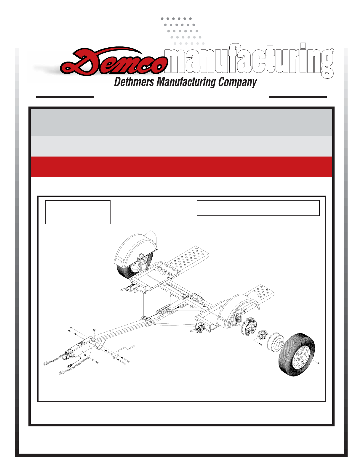
KAR-KADDY
8-03
RD20005,Rev 3
KK260 (8
OPERATORS MANUAL
ASSEMBLY
CALIBRATION
OPERATION
REPLACEMENT PARTS
WIDE) & KK360 (8-1/2 WIDE)
READ complete manual CAREFULLY
BEFORE attempting operation.
DEMCO Dethmers Mfg. Co. 4010 320th St. P.O. Box 189 Boyden, IA 51234
PH: (712) 725-2311 Toll Free: 1-800-543-3626 FAX: 1-800-845-6420
www.demco-products.com
Page 1
Page 2

Introduction
Thank you for purchasing a Demco Kar-Kaddy. We feel you have made a wise choice and hope you
are completely satisfied with your new piece of equipment.
GENERAL INFORMATION
1. Unless otherwise specified, high-strength (grade 5)
(3 radial-line head markings) hex head bolts are
used throughout assembly of this piece of equipment.
2. Whenever the terms "LEFT" and "RIGHT" are
used in this manual it means from a position behind
the
Kar-Kaddy and facing forward.
TABLE OF CONTENTS
General Information................................................................................................................ Page 2
Bolt Torque............................................................................................................................. Page 3
Safety, Maintenance, & Important Loading Instructions......................................................... Page 4
Testing Lights Before Use.................................................................................................... Pages 5
Loading Instructions ............................................................................................................ Page 5-7
Kar-Kaddy 260 and 360 Parts Breakdown and List ............................................................ Page 8-9
Kar-Kaddy 260 and 360 Parts List cont. .............................................................................. Page 10
Limited Warranty Information ............................................................................................... Page 11
DA66 Brake Actuator Parts Breakdown and List................................................................. Page 12
DA603 Brake Actuator Parts Breakdown and List............................................................... Page 13
DA91 Brake Actuator Parts Breakdown and List................................................................. Page 14
10" Self-Adjusting Brake Cluster Parts Breakdown and List ............................................... Page 15
Optional Surge Brakes Parts Breakdown and List .............................................................. Page 16
KK260 and KK360 Parts Assembly Instructions .......................................................... Pages 17-18
Wiring and Fender Assembly Instructions ........................................................................... Page 19
Kar-Kaddy Toe-In Adjustment.............................................................................................. Page 20
Wheel Jack, Deflector, & Light Bar (optional) Parts Breakdown and List ............................ Page 21
Winch, Tool Box, & Spare Tire w/Mounting Bracket (optional) Parts Breakdown and List .. Page 22
Notes.................................................................................................................................... Page 23
3. When placing a parts order, refer to this manual for
proper part numbers and place order by PART NO.
and DESCRIPTION.
"Reporting Safety Defects"
If you believe that your vehicle has a
defect which could cause a crash or could
cause injury or death, you should immediately inform the National Highway Traffic
Safety Administration (NHTSA) in addition
to notifying Dethmers Manufacturing Company (DEMCO).
If NHTSA receives similar complaints,
it may open an investigation, and if it finds
that a safety defect exists in a group of
vehicles, it may order a recall and remedy
campaign. However, NHTSA cannot become involved in individual problems be-
tween you, your dealer, or Dethmers Manufacturing Company (DEMCO).
To contact NHTSA, you may either
call the Auto Safety Hotline toll-free at
1-800-424-9393 (or 366-0129 in
Washington, D.C. area) or write to:
NHTSA,
U.S. Department of Transportation
Washington, D.C. 20590.
You can also obtain other information
about motor vehicle safety from the Hotline.
Page 2
Page 3
BOLT TORQUE
TORQUE DATA FOR STANDARD NUTS, BOLTS, AND CAPSCREWS.
Tighten all bolts to torques specified in chart unless otherwise noted. Check tightness of bolts
periodically, using bolt chart as guide. Replace hardware with same grade bolt.
NOTE: Unless otherwise specified, high-strength Grade 5 hex bolts are used throughout
assembly of equipment.
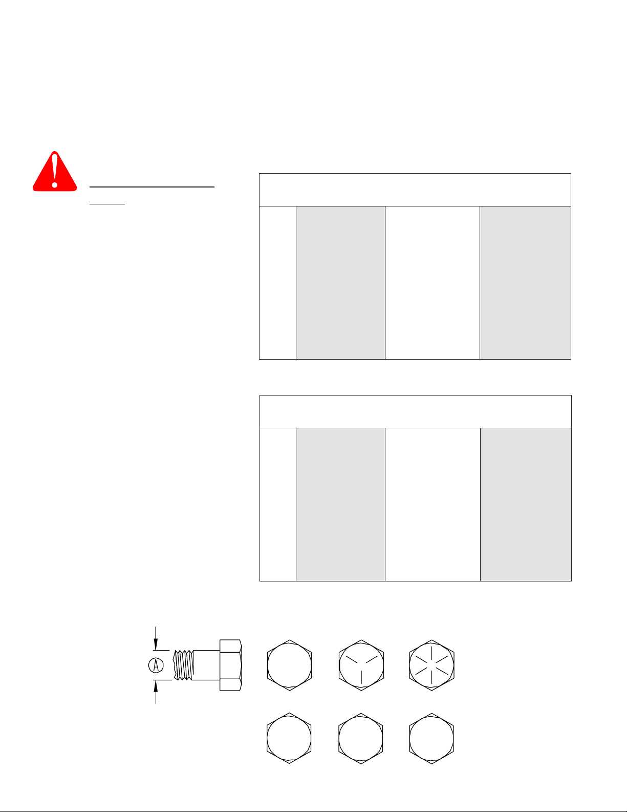
Bolt Torque for Standard bolts *
Torque Specifications
Torque figures indicated are valid for
non-greased or non-oiled threads and
heads unless otherwise specfied.
Therefore, do not grease or oil bolts or
capscrews unless otherwise specified
in this manual. When using locking
elements, increase torque values
by 5%.
* GRADE or CLASS value for bolts
and capscrews are identified by their
head markings.
GRADE 2 GRADE 5 GRADE 8
A lb-ft (N.m) lb-ft (N.m) lb-ft (N.m)
1/4 6 (8) 9 (12) 12 (16)
5/16 10 (13) 18 (25) 25 (35)
3/8 20 (27) 30 (40) 45 (60)
7/16 30 (40) 50 (70) 80 (110)
1/2 45 (60) 75 (100) 115 (155)
9/16 70 (95) 115 (155) 165 (220)
5/8 95 (130) 150 (200) 225 (300)
3/4 165 (225) 290 (390) 400 (540)
7/8 170 (230) 420 (570) 650 (880)
1 225 (300) 630 (850) 970 (1310)
Bolt T orque for Metric bolts *
CLASS 8.8 CLASS 9.8 CLASS 10.9
A lb-ft (N.m) lb-ft (N.m) lb-ft (N.m)
6 9 (13) 10 (14) 13 (17)
7 15 (21) 18 (24) 21 (29)
8 23 (31) 25 (34) 31 (42)
10 45 (61) 50 (68) 61 (83)
12 78 (106) 88 (118) 1 06 (144)
14 125 (169) 140 (189) 170 (230)
16 194 (263) 216 (293) 263 (357)
18 268 (363) -- -- 364 (493)
20 378 (513) -- -- 515 (689)
22 516 (699) -- -- 702 (952)
24 654 (886) -- -- 890 (1206)
GRADE-2 GRADE-5 GRADE-8
CLASS 8.8 CLASS 9.8 CLASS 10.9
8.8
9.8
Page 3
10.9
Page 4

WARNING:
!
!
Safety is of utmost importance at all times. There are
several items that must be checked each time
using and
Make sure all bolts are properly tightened and those
requiring a set torque are up to specifications:
Tie Rod Castle Nut - 75 ft./lbs.
Lug Nuts - 75 to 80 ft./lbs.
Check Lug Nut tension after the first 5 miles and
periodically thereafter.
The ball hitch must latch securely around the ball and
the safety lock pin or lever must be in position to lock the
hitch on the ball.
RECOMMENDED BALL HEIGHT: 18 inches to the top
of the ball on the towing vehicle.
Hook the towed vehicle safety chains to the frame of the
vehicle directly above the area where the chain is
mounted on the Kar Kaddy. Leave some slack in the
chain to allow suspension movement.
Check to make sure that all lights are in proper working
order.
FAILURE TO FOLLOW THESE INSTRUCTIONS CAN RESULT IN LOSS OF TOWING VEHICLE CONTROL,
SEPERATION OF THE TOW DOLLY FROM THE TOWING VEHICLE, SEPERATION OF THE TOWED VEHICLE FROM
THE TOW DOLLY, CAUSING SEVERE PERSONAL INJURY, DEATH, OR PROPERTY DAMAGE.
SAFETY
before
while using the Kar Kaddy.
Rear Wheel Drive: Disconnect the towed vehicle
driveshaft for rear wheel drive vehicles with automatic
transmission.
For manual transmission: Consult your vehicle owners
manual for towing suitability with the drive shaft connected.
MAINTENANCE
Periodically check all bolts and nuts to insure proper
tension or torque.
Grease the king pin and tie rod end grease zerks every
2500 miles.
An occasional drop of oil may be required on the moving
parts of the tie down winches.
A light film of oil should periodically be applied to steering
stabilizer arm to prevent rust.
NOTE: Proper toe-in is 1/32". This is preset at the
factory.
The operator should periodically have the toe-in checked
and adjusted if needed at a qualified alignment shop.
Improper toe-in can result in irregular tire wear.
Examine the winches and straps, making sure they are
in good conditon.
Be certain the safety lock pins are locking the strap
winches.
Retighten straps over the tires after the first 5 miles and
every 50 miles thereafter. Ensure that they are tight.
The KK260 tires must be inflated to the recommended
50 PSI.
The KK260SB, KK360 and KK360SB tires must be
inflated to the recommended 50 PSI.
The strap on the optional tongue winch must be in good
condition and should be stored neatly on winch when
not in use.
NOTE: The winch strap must not be left connected to
the towed vehicle after it is loaded and strapped down.
Make sure the optional light bar is fastened
the rear of the towed vehicle.
The wires to the optional light bar should be run along the
car and fastened so as not to damage the finish of the
towed vehicle.
NOTE: This unit cannot be backed up, when loaded or
with the steering lock pin removed.
All vehicles mounted on the Kar Kaddy must be mounted
with the front of the vehicle facing forward.
securely at
IMPORTANT LOADING INSTRUCTION
Check your wheel tie-down straps.
Your Kar Kaddy is equipped with custom made
wheel tie-down straps of a standard size that will fit
most tires, however if your tires are too large or too
small you will want to exchange these new straps
for the proper size straps.
1. Tire too large - This is very obvious the strap
will not basket over the tire properly, call us,
we will provide at NO Charge on an exchange
basis, the proper size strap. You must return
your new unused straps and provide us with
the Make and Model car and the tire size.
2. Tire too small - This is not as obvious, the
basket will fit down over the tire very well, the
problems cannot be readily seen. You must
tighten the straps down solid and then check
on the inside of the tire and be sure the strap,
when tightened does not come in contact with
any metal that may cause wear or cutting such
as strut mounts. If there is contact, you need a
smaller strap, call us, we will provide on a NO
Charge, exchange basis, the proper size strap.
You must return your new unused straps and
provide us with the Make and Model car and
tire size.
Thank you for Purchasing
Page 4
Products.
Page 5
TESTING LIGHTS BEFORE USE
1. Check that the WHITE (ground) wire of the wiring harness
is connected to the Kar Kaddy frame and the WHITE
(ground) wire is connected to the frame of the towing
vehicle.
2. With headlights in "ON" position, the tail lights, the light
cluster bar, the license plate light, and the clearance lights
should be lighted.
3. Start engine and have someone depress brake pedal.
Brake lights of tow dolly and towing vehicle should come
"on" and "off" simultaneously with each application.
4. Turn left turn signal on. Left turn light of Kar Kaddy and
towing vehicle should flash simultaneously. Should the
turn signal lights of the trailer function opposite to those of
the towing vehicle, it is probable that the YELLOW (Driver
side) and GREEN (Passenger side) wires have been
reversed. Check the plug connection under the tongue of
the Kar Kaddy to make sure wire colors are not crossed at
that point. If plug connection is incorrect, correct problem
by reversing yellow and green wire connection on the
towing vehicle.
LOADING INSTRUCTIONS
Refer to load limits on inside of front cover.
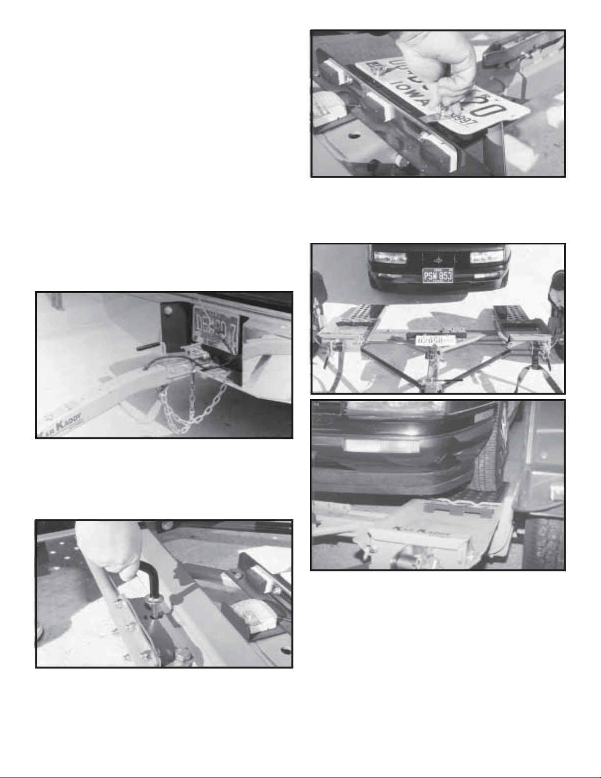
Step 3. Loosen wing nut on back of license plate holder, turn
the clip on the front to a horizontal position and put license in the
"down" position. Turn the clip back so it rests against the back
of the light bar to hold the license down and tighten wing nut.
(License must be "UP" with the tow dolly empty).
Step 1. Secure ball coupler to 2" (5,000 lb. capacity) towing
vehicle ball only. Make sure that the hitch and the hitch ball
are in good condition and not rusted, loose or stripped.
Recommended ball height is 18" to the top of the ball.
Make sure hitch is locked down and secured with safety clip.
Criss-cross safety chains under tongue and secure to towing
vehicle frame.
Step 2. Remove black locking pin BEFORE loading vehicle
onto the Kar Kaddy. The removal of the locking pin allows
"Auto Steer" to operate. When towing the dolly empty, this pin
must be in place.
Step 4. Before loading (and unloading) towed vehicle make
sure platform and towed vehicle are in straight alignment. Tow
dolly must be completely and properly hooked up to the towing
vehicle. Towing vehicle must be larger and at least 1000
lbs. heavier than the tow dolly and towed vehicle combined.
IMPORTANT: Tire tread width or body width of towed
vehicle must not exceed:
KK260 - 70" max. (outside to outside),
42" min. (inside to inside),
72" max. (body width).
KK360 - 76" max. (outside to outside),
42" min. (inside to inside),
78" max. (body width).
Page 5
Page 6
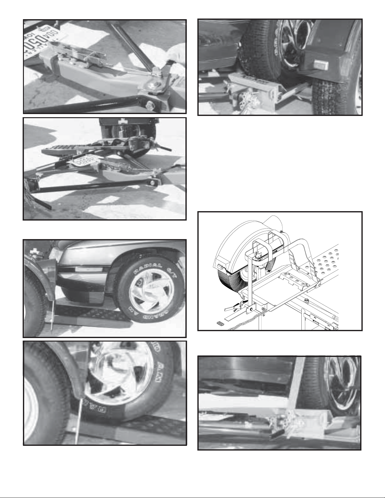
Step 5. Grasp bed release handle on tongue and pull
toward coupler. This releases the tilt bed to permit loading.
Step 7. Drive vehicle onto the platform - front forward - until
tires touch the wheel stops at the front of each side of the
platform and the platform tilts to a flat position. Make sure the
car is centered on the platform. Towed vehicle tires must fit in
wheel troughs without overhanging sides. Engage towed
vehicle parking brake. Shift loaded car into "park" and lock
steering wheel with front tires in a straight position. If the car
does not have a locking steering column the steering wheel
must be tied securely with front tires in a straight position.
Rear Wheel Drive: Disconnect towed vehicle driveshaft for
rear wheel drive vehicles with automatic transmission.
For manual transmission: Consult your vehicle owners
manual for towing suitability with the drive shaft connected.
Step 6. With someone safely guiding you, slowly drive vehicle onto platform FRONT FORWARD. (Any vehicle mounted
on tow dolly must be mounted with front of the vehicle facing
forward.) Drive the car forward until the tires touch the ramps.
Make sure the tire is aligned to ascend onto the ramps.
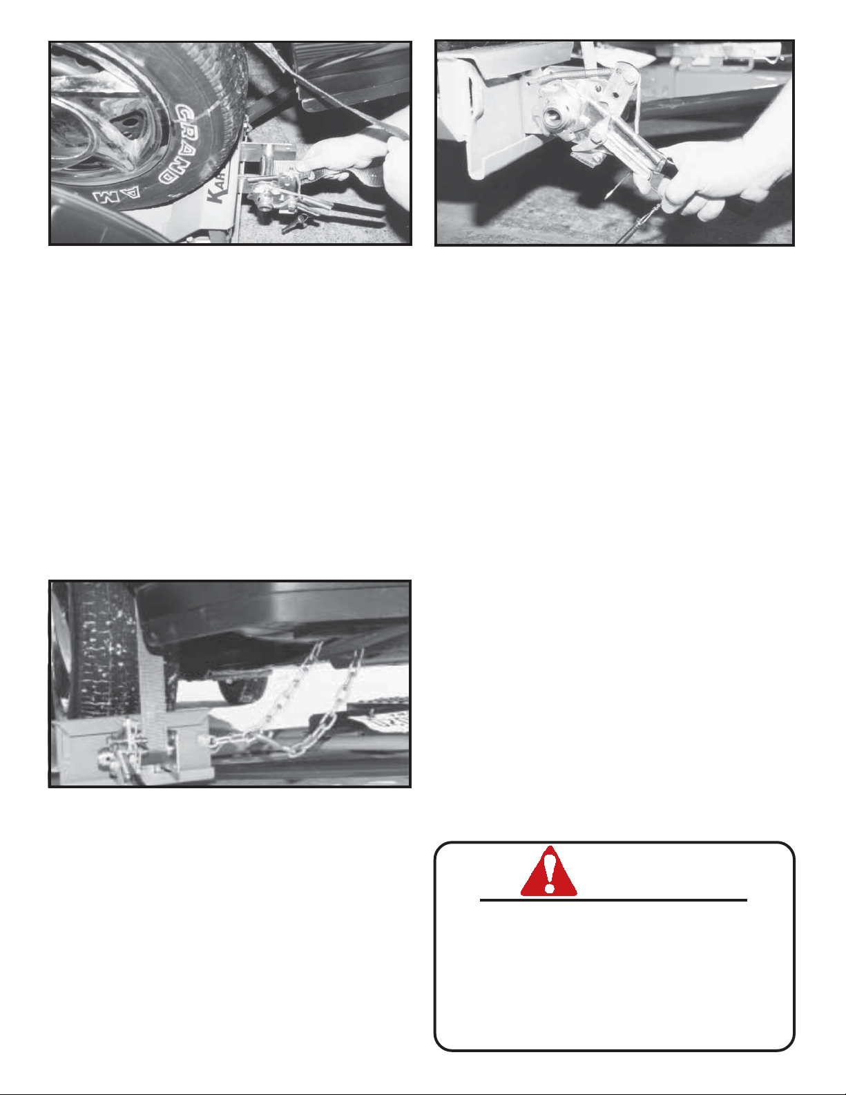
Step 8. Place one tie-down strap over each tire and secure
hooks to rods located at the rear of each wheel platform. The
short side of the hook must face the rear of the Kar Kaddy.
Step 9. Be sure tie-down winch is centered with the tire before
tightening straps.
Page 6
Page 7
A
B
Step 10. Thread tie-down strap through the slotted tube on the
tie-down winch. Pull approx. 6" of strap through this slot.
Begin tightening strap making sure the tail becomes enclosed
by the strap coming over the tire. Tighten the straps ensuring
that the strap fed through the slot binds between the shaft and
the strap being wound onto the winch shaft. While tightening
straps, pull cross strap forward to ensure even tightening.
NOTE: Be sure to tighten straps until each tire starts to
flatten against tire stop. After each strap is tight, insert a
safety pin in each winch. Disengage towed vehicle parking
brake.
Straps must be retightened after first 5 miles of travel. Check
straps every 50 miles thereafter to ensure they are tight and
not rubbing or fraying.
Step 11. Make sure the tie-down strap is the correct size for
the auto tire. See page 11 of this instruction for proper fit and
exchange instructions.
Step 13. TO UNLOAD towed vehicle. Make sure that platform and vehicle are straight. Reinstall driveshaft. Ensure that
towed vehicle parking brake is fully engaged, then unhook the
towed vehicle safety chains, and release the tie-down straps.
NOTE: Tie down straps must be "quick -released" by grasping
ratchet pawl (A) and ratchet handle (B) simultaneously and
pushing down sharply. This process will permit easy removal
of strap from winch.Swing the wheel platform locking latch
handle forward, towards the coupler. This will allow the
platform to tilt as you slowly drive off. Make sure the winch
ratchet handles are horizontal. Replace the "Auto Steer"
locking pin (for towing empty).
Step 14. To pull the Kar Kaddy empty, make sure "AutoSteer" LOCKING PIN IS IN PLACE and towing vehicle
safety chains are up and hooked. Tie-down winch handles
should be left in a down postion (horizontal) position with
safety pins in place when towing loaded or empty. DO NOT
ATTEMPT TO PULL KAR KADDY WITH WHEEL PLATFORM IN LOADING (tilted) POSITION.
DAMAGE PREVENTION
Check your vehicle manual or registration for vehicle weight.
Towing vehicle must be larger and at least 1,000 lbs. heavier
than the towed vehicle and tow dolly combined.
Do not pack goods in car that is being towed. Overloading the
Kar Kaddy or exceeding the width limit may result in damage
to both car and Kar Kaddy.
Step 12. Hook the towed vehicle safety chains to frame of
vehicle directly above the area where the chains are mounted
on the Kar Kaddy. Leave some slack in the chains to allow
suspension movement of the towed vehicle.
Page 7
REAR WHEEL DRIVE PRECAUTIONS
Disconnect towed vehicle driveshaft for rear wheel drive
vehicles with automatic transmission. Simply placing transmission in neutral is not sufficient to prevent damage to
transmisssion.
For manual transmission: Consult your vehicle owners manual
for towing suitability with the drive shaft connected.
ALL VEHICLES MOUNTED ON THE KAR KADDY MUST BE
WITH THE FRONT OF THE VEHICLE FACING FORWARD.
SAFETY
Examine winches and straps to make sure they are in
good condition.
Check wheel nuts every trip.
Tires must be inflated to recommended pressure by tire
manufacturer.
Be certain the safety lock pins lock the strap winches.
Retighten the straps over the tires after the first 5 miles
of travel. Check straps every 50 miles therafter to
ensure they are tight and not rubbing or fraying.
Page 8
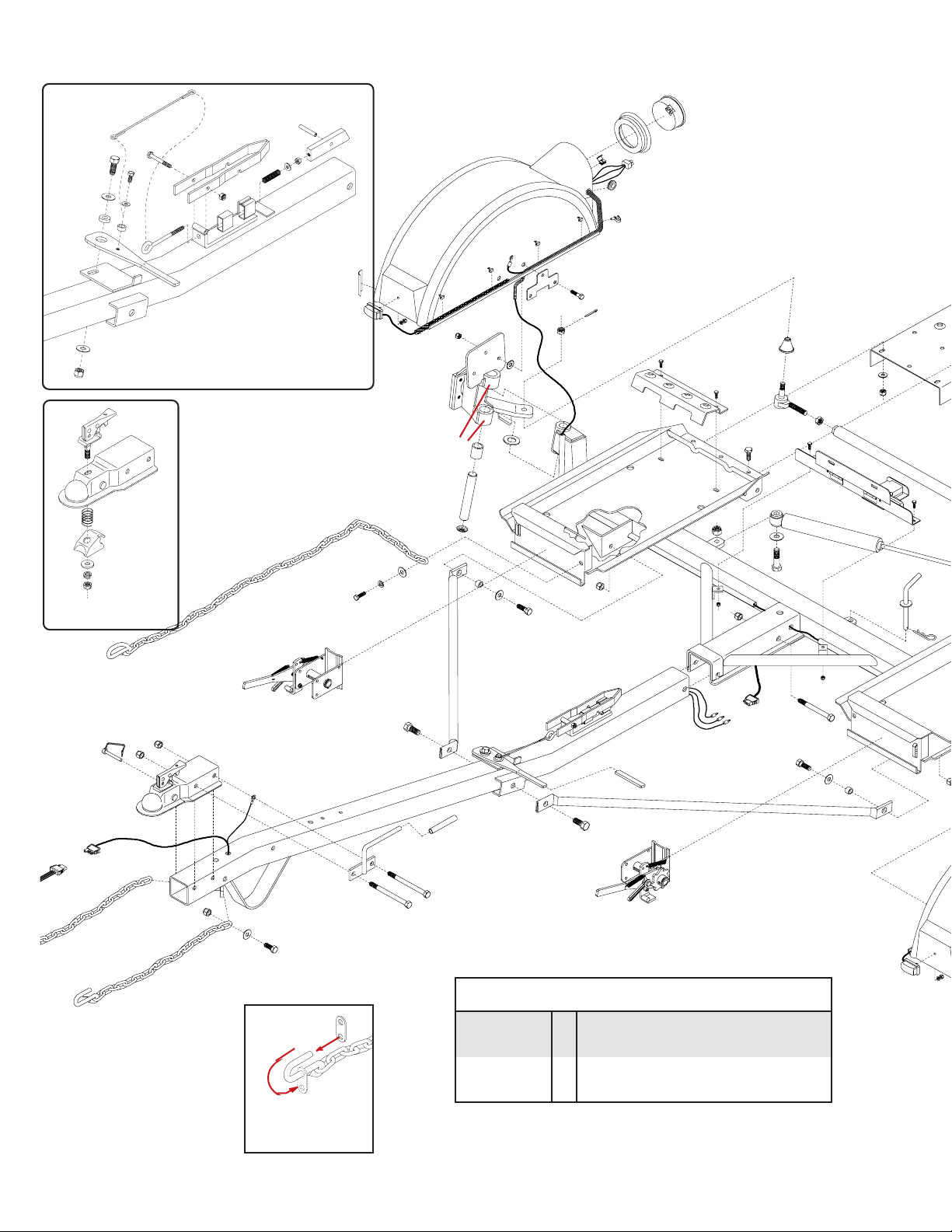
KK260 (8'wide) and KK360 (8-1/2' wide) PARTS BREAKDOWN
128
121
87
5217
117
46
120
116
for
Fulton
5000 lb.
coupler
55
118
119
55
42
not included
Coupler Repair Kit
126
123
124
127
129
122
125
KIT #5511
TILT-BED LATCH
ASSEMBLY
53
99
47
100
86
63
46
98
75
59
61
60
Right Fender
113
106
114
108
62
65
54
55
56
105
*69
107
42
33
112
*69
104
110
111
109
90
103
89
51
90
51
58
88
57
80
78
*69
*69
66
72
81
46
75
82
2
83
5
34
45
37
35
42
38
44
45
Part# 07426
Hook Retainer
Replacement Only
43
46
47
71
2
48
39
52
49
35
10
52
41
40
49
1
DECALS
DECAL
NO. QTY. DESCRIPTION
RD21002 1 Instruction Decal
RD21003 - 5 ft. Gold Striping (for fenders)
RD21001
DA21005 - Check Wheel Nuts & 50 Psi. C Range BSW
ZA21003 1 VIN
4 Kar Kaddy Decal (brown)
(KK360, KK260SB, KK360SB)
36
58
50
56
55
54
100
Page 8
Page 9

26
25
27
26
25
(not available)
24
32
30
29
84
30
31
28
130
51
78
79
Left Fender
64
91
68
92
77
76
87
67
75
115
102
109
74
104
27
103
93
27
42
55
73
KK6LBAS
License Plate Mount
and Light Cluster
31
85
*70
*70
*70
*70
94
95
Left Winch Shown
23
10
21
17
12
13
14
15
11
9
8
REF. PART
NO. NO. QTY. DESCRIPTION
1. 5432 1 Left Ratchet Winch Assembly (Plated)
2. 5433 1 Right Ratchet Winch Assembly (Plated)
3. 03569-95 1 Ratchet Frame
4. 03570-95 1 Left Spool Tube
- 03571-95 1 Right Spool Tube
5. 03577 1 Heavy Duty External Snap Ring
6. 03574-95 1 Ratchet Handle
7. 03668 1 18 Ga. Shim Washer
8. 03575-95 1 Left Ratchet Gear
- 03576-95 1 Right Ratchet Gear
9. 03666 1 5/16" x 1-1/4" Roll Pin
10. 02243 1 Black Vinyl Hand Grip
11. 05450 1 Winch Pawl
12. 01864 2 Winch Pawl Spring SS
13. 05449 1 Winch Pawl Bushing SS
14. 00059 1 3/8" Flatwasher
15. 05444 1 3/8"-16 UNC x 3/4" Hex Bolt w/epoxy Gr.5
16. 03572-95 1 Left Ratchet Pawl Arm
- 03573-95 1 Right Ratchet Pawl Arm
17. 03578 1 5/16"-18 UNC x 1/2" Shoulder Screw
18. 01998 1 5/16" Flatwasher SS
19. 02002 1 1/4" Flatwasher SS
20. 02772 2 1/4"-20 UNC Nylon Locknut
21. 04055 1 1/4"-20 UNC x 1" Hex Hd. Bolt Gr.5
22. 00214 1 1/4" Flatwasher
23. 05337 1 Lock Pin w/Cable
- 5192 License Plate Light and Light Cluster
24. 04505-25 1 License Plate and Light Cluster Bracket
25. 04176 4 1/4"-20UNC x 3/4" Carriage Bolt
26. 02519 2 1/4"-20UNC x 1/2" Slotted Truss Head Bolt
27. 02163 1 Square License Plate Light w/washer and nut
- 02164 - Clear License Plate Light LENS ONLY
20
12
22
19
20
5
16
18
4
6
7
3
Page 9
Page 10

REF. PART
NO. NO. QTY. DESCRIPTION
29. 02580-95 1 License Plate Clip
30. 02770 2 1/4-20UNC Nylon Insert Wing Nut
31. 01077 2 1/4"-20UNC Serrated Locknut
32. 04513 1 Light Cluster
10. 02243 2 Black Vinyl Hand Grip
33. 01883 11 Electrical Wire Splicer
34. 01881 1 Trunk Connector
35. 04785 1 Front Half Trailer Wiring Harness
36. 04786 1 Rear Half Trailer Wiring Harness
37. 01855 1 Safety Lock Pin
38. 04496 1 5000 lb. Ball Coupler (lever lock)
39. 02288-95 1 Bolt on Handle
- 04017-95 1 Bolt on Handle (used with brakes)
40. 01338 2 1/2"-13UNC x 4-1/2" Hex Head Bolt (gr.5)
- 01975 2 1/2"-13UNC x 5" Hex Hd. Bolt (gr.5) (used w/ brakes)
41. 02189 1 1/2" I.D. Rubber Handle Grip
42. 02178 13 1/2"-13UNC Nylon Insert Locknut
43. 01863 1 5/8" Grommet for wiring harness
44. 02771 2 7/16"-14UNC Nylon Insert Locknut
45. 01853 2 24" Transport Safety Chain w/ Hook
- 02383 2 36î Transport Chain w/ Hook (used w/ brakes)
46. 00059 9 3/8" Flat Washer
47. 01898 4 7/16"-14UNC x 1-1/4" Hex Head Bolt (gr.5)
48. 07077-26 1 Kar Kaddy Tongue
49. 03503 2
50. 02434 1 5/8"-13UNC x 4-1/2" Hex Head Bolt (gr.5)
51. 02587 3 5/8"-13UNC Nylon Insert Locknut
52. 02747-25 2 Bracing Strut
53. 02383 2 36" Safety Chain
54. 02579-95 2 Pivot Bushing
55. 00085 12 1/2" Flatwasher
56. 01254 2 1/2"-13UNC x 1-1/2" Hex Head Bolt (gr.5)
57. 04815 2 Grommet
58. 02772 8 1/4"-20UNC Nylon Insert Locknut
59. 04642 2 Grease Zerk
60. 01731 4 1-1/4" Dust Cap
61. 01734 2 1" dia. x 6-1/2" lg. King Pin
62. 01732 4 1"I.D. x 1-1/4"O.D. x 1-1/2"lg. Bushing (brnz)
63. 04165-26 1 Right Wheel Carrier
64. 04166-26 1 Left Wheel Carrier
- 04642 4 1/4"-28UNF Grease Zerk
65. 05587 2 1" I.D.x 14 GA Narrow Rim Machine Washer
66. 07075-26 1 KK260 Main Frame (8' wide)
- 07076-26 1 KK360 Main Frame (8-1/2' wide)
- 09528-26 1 KK260SB Main Frame (8' wide)
- 09529-26 1 KK360SB Main Frame (8-1/2' wide)
67. 04369 2 Hub and Spindle (115mm B.C.)
- 02917 - Replacement 12mm x 1.5 Stud Bolt
68. 02210 8 7/16"-20UNF x 1-1/4" grade 8 Epoxied Bolt
*69. 5179 1 Right Tie Rod End w\Right Hand Threads
*70. 5178 1 Left Side Tie Rod End with Left Hand Threads
71. 07426 4 Rubber Hook Retainer
72. 01905 1 9/16"-18UNF Jam Nut w/Right Hand Threads
73. 01904 1 9/16"-18UNF Jam Nut w/Left Hand Threads
74. 01869-26 1 Tie Rod (KK260 - 8' wide)
- 04771-26 1 Tie Rod (KK360 - 8-1/2" wide)
75. 02592 16 3/8"-16UNC Nylon Insert Locknut
76. 01871-26 1 Tie Rod Shock and Stop Mount Back-up Plate
77. 01870-26 1 Tie Rod Shock and Stop Mounting Clamp
78. 02696 2 5/8"-11UNC x 2-3/4" lg. Hex Head Bolt (gr.5)
79. 00907 6 3/8"-16UNC x 1" Hex Head Bolt (gr.5)
80. 00477 1 5/8" Flatwasher
81. 01729-26 1 Steering Stabilizer Cylinder
5/8"-11 UNC x 1-1/4" Epoxied Hex Hd Bolt (gr.5)
REF. PART
NO. NO. QTY. DESCRIPTION
82. 01718-95 1 Locking Pin
- 02189 1 Black Handle Grip
83. 00182 1 Small Hair Pin
84. 03528 2 Tie Down Strap w/J-Hook
85. 04503-25 2 Tilt Bed Ramp (KK260 - 8' wide)
- 04772-25 2 Tilt Bed Ramp (KK360 - 8-1/2' wide)
86. 00078 2 7/16" Lockwasher
87. 00967 8 1/2"-13UNC x 1-1/4" lg. Hex Head Bolt (gr.5)
88. 04167 6 7/16"-20UNF x 1" lg. Hex Head Bolt (gr.8)
89. 04171-25 2 Rear Tire Stop (KK260 - 8' wide)
- 04773-25 2 Rear tire Stop (KK360 - 8-1/2' wide)
90. 00523 4 3/8"-16UNC x 1-1/4" lg. Hex Head Bolt (gr.5)
91. 00789 2 3/8"-16UNC x 3/8" lg. Hex Socket Set Screw
92. 01930 2 3/8"-16UNC x 1/4" lg. Hex Socket Set Screw
93. 04941 2
- 04826 2 ST205/75R14 "C"Range BSW Radial Tire
94. 04367 2 Rim (6 x 14) (serial # 19001 & later)
95. 02933 10 Chrome Lug Nut
- 5333 1 LH Fender Assembly (qtyís below are for 1 fender)
- 5334 1 RH Fender Assembly (qtyís below are for 1 fender)
28. 00214 3 1/4" Flatwasher
97. 05356 1 Left Fender
98. 05355 1 Right Fender
- 4 Stainless Steel Ground Strap
99. 04508 1 Amber Fender Reflective Decal
100. 04498 1 Front Fender Light with lead wire
101. 01769 1 Kar Kaddy Mud Flap
102. 05338 2 1/4"-20UNC x 3/4" lg. Brown Sltd Truss Bolt
103. 05446 1 4-1/2" Enclosed Round Tail Light
104. 05447 1 Rubber Grommet for 05446 Light
105. 04424-95 1 Fender Back-up Plate
106. 02316 1 White Ground Wire
107. 00914 3 3/8"-16UNC x 1-1/2" lg. Hex Head Bolt (gr.5)
108. 04499 3 3/8" I.D. External Tooth Lockwasher
109. 02313 1 3-Way Plug Pigtail (tail light)
110. 04944 1 5/8" Grommet (thin wall)
111. 05443 1 Cable Hanger - wire harness
112. 02298 1 22-1/2" Wire Protector Loom
113. 04425 4 Tinnerman Fender Clamp
114. 04515 1 17-1/2" Wire Protector Loom
115. 04804 1 Red Fender Reflective Decal
116. 05449 1 Spacer Bushing - Stainless Steel
117. 05444 1 3/8"-16 UNC x 3/4" Epoxied Hex Bolt (Gr 5)
118. 03382-95 1 Latch Handle Pivot Bushing
119. 03574-95 1 Latch Handle
120. 03434 1 5/16"-18 UNC x 5-1/4" Eye Bolt
121. 04221 1 5/16"-18 UNC x 2-1/2 Hex Head Bolt (Gr 5)
122. 02802 1 5/16-18 UNC Nylon Insert Locknut
123. 03381-95 1 Latch Catch
124. 00007 1 5/16"-18 UNC Hex Nut
125. 03379-95 1 Latch Block
126. 03435 1 Roll Pin (5/16" x 2-1/4")
127. 03499 1 Latch Spring - Stainless Steel
128. 03433 1 Latch Cable
129. 00004 1 5/16" Flatwasher
130. 04168 6 7/16"-20UNF Nylon Insert Locknut
- CMO8021 12 oz. Buckskin Touch-up Paint (Aerosol)
- IC8633 12 oz. Brown Touch-up Paint (Aarosol)
P195/75R14 "B" Range BSW Radial Tire (KK260)
(KK360,KK260SB,KK360SB)
* Indicates this kit includes appropri-
ate tie rod end (left or right hand
threads), grease zerk, rubber cup,
cotter pin and castle nut.
Page 10
Page 11

DEMCO PRODUCTS - KAR KADDY
ORIGINAL PURCHASERíS LIMITED WARRANTY
1. Extent and Duration of this Warranty:
Your Demco Kar Kaddy is warranted to be free from defects in
materials and workmanship under normal use and service for a
period of one year after date of purchase by the original (first)
retail owner, or until it is resold or transferred by the original
owner. New Departure Hyatt Hubs used on the KK260 and
KK360 are warranted for a period of three years after the date of
purchase by the original (first) retail owner or until itís resold or
transferred by the original owner. Tires and lights are not
included in this warranty.
Tires are warranted by the manufacturer against defects in
materials and workmanship, but not against road hazards.
Any part of the Demco Kar Kaddy, except tires and lights, found,
in the judgement of the manufacturer to be defective in materials
or workmanship will be repaired or replaced at the manufacturerís
option without charge for parts or labor to the original owner.
2. Manufacturer and Warrantor of Tow Dolly:
Dethmers Manufacturing Co.
4010 320th Street
P.O. Box 189
Boyden, IA 51234
(712) 725-2311
The manufacturer and warrantor of the tires has his name
permanently molded into the tires. Tire warranty questions and
claims can be taken directly to an authorized dealer of the tire
manufacturer.
3. Repair or Replacement Procedure:
If your Demco Kar Kaddy develops a defect (except for tires or
lights) during the warranty period, promptly notify Dethmers
Manufacturing Co. customer service department. Until such
notice is received, Warrantor will not be responsible for any repair
or replacement.
Upon receipt of notice from you, Warrantor will have a choice of
options in replacing any part it determines to be defective:
a) Warrantor may require you at your own expense to deliver
or ship the part to its factory or authorized dealer. Any
defective part will be repaired or replaced and returned to
you free of charge. Any part returned to Warrantor and
found not to be defective will be returned to you freight
collect with an explanation.
b) Warrantor may elect to ship a new part to its dealer to be
exchanged free of charge for the defective part returned
by you to the dealer.
c) Warrantor may elect to ship or deliver a replacement part
to your address.
Warranty claims on tires should be presented to a local authorized dealer of the tire manufacturer. Provide proof of purchase
when making a tire warranty claim.
In addition, the warranty does not extend to repairs made
necessary by normal use of parts, accessories or other equipment which in the judgment of Warrantor, are either incompatible with the Demco Kar Kaddy, or affect its operation, performance or durability.
This warranty does not cover:
1) normal wear and tear
2) road film or gravel damage to paint
3) paint
4) rust damage
5) Any Demco Kar Kaddy that has been loaded in excess of the
load capacity stated on the tow dolly identification label.
Warrantor has a policy of continuous product improvement. We
reserve the right to change or improve the design of any Demco
Kar Kaddy model, including but not limited to state of the art
changes, without assuming any obligation to modify any tow
dolly previously manufactured.
Warrantor assumes no responsibility to the owner for loss of use
of the tow dolly, loss of time, inconvenience or other damage
consequential or otherwise, including, but not limited to expense for gasoline, expense of transporting the tow dolly to the
dealer and expense of returning the tow dolly, mechanicís
travel time, telephone or telegram charges, road service/towing
charges, rental of another tow dolly during the time warranty
repairs are being performed, travel, lodging, loss or damage to
personal property or loss of revenue or earnings.
5. Limitations of Implied Warranties:
All implied warranties, if any, expire and terminate upon expiration of this warranty. Some states do not allow limitation on
how long an implied warranty lasts, so this limitation may not
apply to you.
6. Limitation of Consequential Damages:
Warrantorís responsibility under this warranty extends solely to
repair or replacement of your Demco Kar Kaddy and its component parts.
Warrantor does not assume responsibility for, nor shall it be
liable for, any special, incidental or consequential damages.
Some states do not allow the exclusion or limitation on incidental or consequential damages, so the above exclusion or
limitation may not apply to you.
7. Use of Vehicle Identification Number (VIN):
The VIN is a 17 digit number located in the lower left corner of
the tow dolly identification label. The label is located on the left
side of the tow dolly frame. Be sure to include the VIN number
in all communications with Warrantor or its dealers concerning
the warranty.
8. Purchaserís Rights:
This warranty gives you specific legal rights, and you may also
have other rights which vary from
4. Limitations on Warranty Coverage:
Coverage under this warranty will be effective only when a copy
of the original invoice, showing the date and location of purchase,
accompanies any claim for warranty.
Warrantor has no liability whatsoever and this warranty is null and void
if any Demco Kar Kaddy has been misassembled or subjected to
neglect, negligence, misuse, accident or operated in any way contrary
to the operating and maintenance instructions as specified in the Demco
Ownerís Manual for that model tow dolly.
This warranty does not cover any tow dolly that has been altered
or modified so as to affect the tow dollyís operation, performance
or durability, or that has been modified to change the intended
use of the tow dolly.
Page 11
Page 12

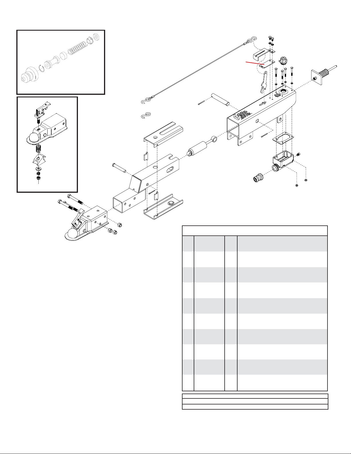
Model DA66 ACTUATOR PARTS BREAKDOWN
18
19
20
19
20
25
13
14
15
16
17
12
21
2
10
10
7
9
2
8
11
7
22
24
5
23
6
1
2
6
3
2
for
6000 lb.
coupler
5495
Coupler Repair Kit
5398 Master Cylinder Repair Kit
(gasket included)
4
ACTUATOR PARTS LIST
REF. PART
NO. NO. QTY. DESCRIPTION
- 8606701 1 DA66 Brake Actuator complete (incl. ref. 1-25)
1. 07599-95 1 6000# 2" Ball Coupler
2. SB23278 4 Roller
3. 05957-95 1 Front Roller Spacer
4. 02166 1 3/8"-16UNC x 2-3/4" Hex Head Bolt (gr.5)
5. 07176 1 3/8" Stover Lock Nut
6. 05684 2 1/2"-13UNC x 4-1/2" Hex Head Bolt (gr.5)
7. 02178 2 1/2"-13UNC Nylon Insert Lock Nut
8. 05959 1 Push Rod Assembly
9. 05692 1 Damper/ Shock
10. 05958-95 2 Rear Roller Spacer
11. *05951 1 Emergency Lever
12. 05955-95 1 Front Cover
13. *SB24700 1 2' Cable with S-Hooks
14. SB10555 2 Replacement S-Hook ONLY
15. 05960 2 5/16"-18UNC x 1/2" Self-Tapping Screw
16. 05424 2 5/16" External Tooth Lock Washer
17. *05693-95 1 Emergency Lever Spring
18. 03876 1 Master Cylinder Cap w/ diaphragm & O-ring
19. 01076 4 1/4-20UNC x 3/4" Hex Head Bolt
20. 00057 4 1/4" Lock Washer
21. 03564-95 1 Outer Case
22. 05681 1 Replacement Master Cyl. Gasket ONLY
23. 05680 1 Master Cylinder with gasket 05681 X
24. SB12098 1 1/8" pipe - 3/6" inverted Flare Fitting
25. 05966-95 1 Back Cover
- 5400 - Lever Replacement Kit (incl. items w/*)
- 5398 - Master Cylinder Repair Kit w/ gasket
- 5495 - Coupler Repair Kit
Please order replacement parts by PART NO. and DESCRIPTION.
Page 12
Page 13

DA603 BRAKE ACTUA TOR P ARTS BREAKDOWN
Components not
sold separately
23
5695 Emergency Lock Cam
Replacement Kit
3
10a
21
13
20
22
11
11
17
12
Item #23
includes cable
23
6
12
18
22
9
7
4
1
20
15
16
14
21
8
5
2
2
10
Item #10 is not
included in 5696
18
5398 Master Cylinder Repair Kit (drum)
(gasket included)
ACTUATOR PARTS LIST
REF.
NO. PART NO. QTY. DESCRIPTION
- 8606301 - Plated Actuator f/ drum brakes
1. 00057 4 1/4î Lock Washer
2. 00062 4 1/4î-20 UNC Hex Nut
3. 00179 1 3/8î-16 UNC Lock Nut (Center Punch)
4. 00618 4 1/4"-20UNC x 2" Hex Head Bolt (Gr.5)
5. SB12098 1 .018 Connector Orifice (Drum Brakes)
6. 02207 1 3/8î-16UNC x 3î Hex Head Bolt (Gr. 5)
7. 03876 1 3 Tab Fill Cap w/ Diaphram & O-Ring
8. 09153 1 Master Cylinder Gasket
9. 10616 1 Composite Master Cylinder (drum)
10. 11367-95 1 Coupler/Inner Slider (plated)
10a. 5698 - Coupler/Inner Slider w/ Lever Lock Assy.
11. 11368 2 Top Plastic Slider
12. 11369 2 Bottom Plastic Slider
13. 11371-95 2 Shock Spacer (plated)
14. 11389-95 1 Rear Shock Pin (plated)
15. 11390-95 1 Outer Case (plated)
16. 11401 2 External Snap Ring
17. SB12426 1 Damper
18. 05687 1 Protective Boot (incl. in 10616 & 5398)
(incl. in 10616 & 11190)
5696 Coupler Repair Kit
(2î lever lock)
**Components not sold separately**
REPLACEMENT KITS
(components not sold separately)
5695 - Emergency Lock Cam Replacement Kit
20. ----- 1 7/16î-14UNC x 1 1/4î Hex Head Bolt (Gr. 5)
21. ----- 1 7/16î-14UNC Lock Nut (Center Punch)
22. ----- 1 Emergency Catch Cam (black oxide finish)
23. ----- 1 Pushrod Assembly (includes cable)
5696 - Coupler Repair Kit (2î lever lock)
5398 - Master Cylinder Repair Kit w/ gasket
Please order replacement parts by PART NO. and DESCRIPTION.
Page 13
Page 14
MODEL DA91 ACTUATOR PARTS BREAKDOWN
8
23
**12
**10
13
8
14
17
14
18
5398 Master Cylinder Repair Kit
(gasket included)
11
not included
28
4
5495
Coupler Repair Kit
2
9
2
1
3
2î Lever Lock Coupler
RATED AT 6000#
BLEEDING THE SYSTEM
The first requirement for safe, sure hydraulic braking is the use
of quality brake fluid. Use only DOT-3 or DOT-4 brake fluid from
a sealed container.
If pressure bleeding equipment is available, follow the
manufacturerís instruction in bleeding the system.
If system must be bled manually, proceed as follows: Fill
master cylinder with fluid. Install bleeder hose on first wheel
cylinder to be bled.
Have loose end of hose submerged in brake fluid in glass
container to observe bubbling.
By loosening the bleeder screw located in the wheel cylinder
one turn, the system is open to the atmosphere through the
passage drilled in the screw. Pump actuator with long steady
strokes. The bleeding operation is completed when bubbles
no longer rise to the surface of the fluid. Be sure to close
bleeder screw securely.
Repeat bleeding operation at each wheel cylinder. During the
bleeding process, replenish the brake fluid, so the level does
not fall below the 1/2 full level in the master cylinder reservoir.
After bleeding is complete, make sure master cylinder reservoir is filled and filler cap is securely in place.
After the bleeding operation has been completed, apply pressure to the system and check the whole brake system for leaks.
28
27
**16
15
15
25
9
26
6
7
9
20
21
5
24
19
Model 91 ACTUATOR PARTS LIST
REF.
NO. PART NO. QTY. DESCRIPTION
1. 09417 1 6000# 2" Lever Lock Coupler (zinc plated)
2. 01896 3 1/2"-13UNC x 4" Hex Head Bolt (gr.5)
3. 02178 3 1/2"-13UNC Nylon Insert Lock Nut
4. 05426 1 Front Shock Pin (drop tube actuators)
5. 11079-95 1 Drop Tube Actuator Slider (plated)
6. SB12426 1 Damper/ Shock
7. 11164-95 1 3 Bolt Mount Outer Case (plated)
8. 05424 2 5/16" External Tooth Lock Washer
9. 02363 2 5/32" x 1 1/4 Cotter Pin(Qty 3 w/drop tube)
**10. 05408 1 3/32" Cable with hooks
11. SB10555 - Replacement S-Hooks ONLY
**12. 05693-95 1 Emergency Lever Spring (plated)
13. 05961 2 5/16"-18UNC x 5/8" Hex Head Bolt (gr.5)
14. 00618 4 1/4-20UNC x 2" Hex Head Bolt (gr.5)
15. 00057 4 1/4" Lock Washer
**16. 05951 1 Emergency Lever Assembly
17. 03876 1 Master Cylinder Cap w/ Diaphragm & O-ring
- 05849 1 O-Ring Only (not shown)
18. 05977 1 Push Rod Assembly
19. 00062 4 1/4-20 UNC Hex Nut
20. 09153 - Plastic Master Cyl. Gasket ONLY
21. 10616 1 Master Cylinder
- 11190 - Master Cylinder
22. SB12098 1 .018 Connector Orifice (Drum Brakes)
23. 03866-95 1 Lever Guide (plated)
24. 05687 1 Master Cylinder Protective Boot
25. 05986-95 1 Connecting Pin (plated)
26. 10965 1 Upper Slider
27. 10966 1 Lower Slider
28. 10967 2 Side Spacers
- 5401 - Lever Replacement Kit (incl. items w/**)
- 5650 - Master Cyl. Replacement Kit (drum)
- 5495 - Coupler Repair Kit
Please order replacement parts by PART NO. and DESCRIPTION
22
19
Page 14
Page 15

10" SELF-ADJUSTING BRAKE CLUSTER and DRUM PARTS BREAKDOWN
4
5
5
7
16
1
6
4
16
2
3
2
8
11
13
10
12
3
19
9
10
17
18
15
17
BRAKE CLUSTER PARTS LIST
REF. PART
NO. NO. QTY. DESCRIPTION
- SB24429 - Left Hand Cluster (shown above)
- SB24428 - Right Hand Cluster
1. SB23871 1 Back Plate Assembly - (NDH Hub Mounting)
2. SB9254 2 Cover Plate - Adjusting Hole
3. SB10954 1 Brake Shoe Kit (includes 2 Primary & 2 Secondary)
4. 04305 2 5/16"-18UNC-Gr5 x 1/2" Hex Hd Bolt
5. 05424 2 5/16" External Tooth Washer
6. SB9776 1 Wheel Cylinder Assembly - Right
- SB9777 1 Wheel Cylinder Assembly - Left
7. 05431 1 Bleeder - replacement
8. SB9783 1 Push Rod
9. SB24047 1 Adjusting Screw Assembly - "R" (for LEFT cluster)
- SB24048 1 Adjusting Screw Assembly - "L" (for RIGHT cluster)
10. SB10958 2 Spring - Shoe
11. SB10961-95 1 Shoe Guide
12. SB23937 1 Cable
13. SB23936 1 Cable Guide
14. SB23724 1 Spring - Adjusting Screw
15. 05415-95 1 Lever - Right
- 05414-95 1 Lever - Left
16. SB10959 2 Pin - Shoe Hold Down
17. SB9789 4 Cup Shoe Hold Down
18. 05983 2 Spring - Shoe Hold Down
19. 03380 1 Spring
17
18
14
17
- SB15845 1 Wheel Cylinder Repair Kit
- SB40929 2 10" Brake Drum
Please order replacement parts by PART NO. and DESCRIPTION.
Brake shoe kit can be ordered for one complete axle only.
(includes spring, cup and boot)
Page 15
Page 16

OPTIONAL SURGE BRAKES (KK260SB and KK360SB) PARTS BREAKDOWN
5
Model DA603
Brake Actuator
2
3
1
SURGE BRAKES PARTS LIST
REF. PART
NO. NO. QTY. DESCRIPTION
1. SB587 1 87" Brake Line
2. 01863 2 Rubber Gommet
3. 02746 1 54" Protective Hose
4. SB7H67 1 7" Brake Hose (rubber)
5. SB536 2 36" Brake Line (KK260SB)
5. SB540 2 40" Brake Line (KK360SB)
6. SB7764 2 Rubber Brake Line Clip
7.
SB10H136
8. 02210 8 7/16"-20UNF x 1-1/4" Epoxied Bolt (gr.8)
9. 04174 4 12mm Retainer Washer (2 per drum)
10. 00496 2 Machine Washer
11. 02549 4 Rubber Protector
12. SB7785 1 3/16 Brake Line Tee
13. SB24429 - Left Brake Cluster
-- SB24428 - Right Brake Cluster
14. SB15545 - 10î Brake Drum
Please order replacement parts by PART NO. and DESCRIPTION.
2 10" Brake Hose (rubber)
12
11
2
4
5
10
7
6
13
8
14
BLEEDING THE SYSTEM
The first requirement for safe, sure hydraulic braking is the use
of quality brake fluid. Use only DOT-3 or DOT-4 brake fluid from
a sealed container.
If pressure bleeding equipment is available, follow the
manufacturerís instruction in bleeding the system.
If system must be bled manually, proceed as follows: Fill
master cylinder with fluid. Install bleeder hose on first wheel
cylinder to be bled.
Have loose end of hose submerged in brake fluid in glass
container to observe bubbling.
By loosening the bleeder screw located in the wheel cylinder
one turn, the system is open to the atmosphere through the
passage drilled in the screw. Pump actuator with long steady
strokes. The bleeding operation is completed when bubbles
no longer rise to the surface of the fluid. Be sure to close
bleeder screw securely.
Repeat bleeding operation at each wheel cylinder. During the
bleeding process, replenish the brake fluid, so the level does
not fall below the 1/2 full level in the master cylinder reservoir.
After bleeding is complete, make sure master cylinder reservoir is filled and filler cap is securely in place.
After the bleeding operation has been completed, apply pressure to the system and check the whole brake system for leaks.
9
Page 16
Page 17

KK260 AND KK360
ASSEMBLY INSTRUCTIONS
1. Place the main frame on blocks or some other sturdy
support so that the frame rests approximately 8" - 10" off
the ground. Attach the tilt bed ramps (#1) as shown using
four 1/2" x 1-1/4" grade 5 bolts (#4), flat washer (#5) and
lock nuts (#6), two on each side of each ramp, and then
three 7/16" x 1" grade 8 bolts (#2) and lock nuts (#3) on the
top of each ramp. Torque 7/16" bolts to 80 ft. lbs. and
torque 1/2" bolts to 75 ft. lbs.
2. Attach rear tire stop (#7) as shown using two 3/8" x 1-1/4"
grade 5 bolts (#8), flat washers (#9) and lock nuts (#10).
These 3/8" x 1-1/4" bolts will also go through the tilt bed
ramps. Torque 3/8" x 1-1/4" bolts to 35 ft. lbs.
3. Hold tongue up to
front of trailer and
locate the three
bullet connectors
extending out the
back of the tongue
Brown
Yellow
Green
and plug into the connector protruding from under the main frame channel. Do
not cross colors when making this connection. See
drawing above. Make sure the the pigtail for the license
plate bracket is out.
4. Mount the tongue (#11) to the front of the Kar Kaddy
mainframe using a 5/8" x 4-1/2" grade 5 bolt (#12) and lock
nut (#13)(torque to 50 ft. lbs). Do not torque over 50 ft. lbs.
or bed will not tilt.
5. Mount the latch handle (#14) to the mounting plate using
the 1/2" x 1-1/4" grade 5 bolt (#15), two 1/2" flatwashers
(#16), bushing (#17), and 1/2" locknut (#18). Put stainless
steel bushing (#19) into latch cable (#20) and secure to
handle using 3/8" x 3/4" grade 5 bolt (#21) and 5/16"
flatwasher (#22). Adjust latch so cable is snug by loosening
bolt and nut and sliding handle forward or back.
Pigtail
Brown/Yellow
Brown/Green
6. Lay the bracing struts (#23) out along the tow dolly tongue
with the back end (the end with the larger hole in it) of the
bracing strut toward the mainframe. Loosely bolt the back
of each bracing strut to the trailer frame as shown using
1/2" x 1-1/2" grade 5 bolt (#24), flatwasher (#25), pivot
bushing (#26) and locknut (#27). Hold up the front end (the
end with the smaller hole) of each bracing strut to the
tongue and secure with two 5/8" x 1-1/4" epoxied hex head
bolts (#28). Torque the 1/2" x 1-1/2" bolt with the pivot
bushing to 75 ft. lbs. Torque the two 5/8" x 1-1/4" epoxied
hex head bolts to 100 ft. lbs.
7. Remove the 7/16" x 1-1/4" bolt (#29), flat washer (#30), and
lock washer (#31) from the front of each wheel platform tire
stop. Slide the tie-down winches into the channel at the
front of the wheel platforms as shown. The ratchet handles
are to the outside of each winch and ratchet springs are to
the top. Attach two towed vehicle safety chains (#32, 36"
long). Secure one chain to each wheel platform tire stop
and replace flat washer, lock washer and 7/16" x 1-1/4"
bolt.
8. Attach each hub and spindle assembly (#33) as shown
using four 7/16" x 1-1/4" grade 8 epoxied bolts (#34).
(Torque to 80 ft. lbs.)
9. Secure the hitch coupler (#35) and the lift handle (#36) to
the front end of the tongue (#11) with two 1/2" x 4-1/2"
grade 5 bolts (#37) and lock nuts (#38). The white ground
wire is attached under the head of the rear bolt attaching
the hitch coupler. (It is very important that a good ground
is made). Torque the lock nuts to 75 - 80 ft. lbs. Tap the
rubber grip (#39) onto the handle with a rubber hammer or
a wooden mallet.
10. Attach the two 24" long transport safety chains (#40) to the
two holes located in the tongue rest using two 7/16" x 11/4" grade 5 bolts (#41), flat washers (#42) and lock nuts
(#43). Torque bolts to 50 ft. lbs.
16
18
14
16
17
15
22
19
40
21
20
Latch Handle
Installation
36" Chain
38
35
43
40
24" Chain
32
42
41
Green/Brown
Wires
31
30
29
28
11
36
37
39
26
23
25
24
28
Page 17
8
7
2
13
Connector
23
24
9
10
3
4
6
5
12
25
26
1
27
Yellow/Brown
Wires
1
33
34
Page 18

11. DO NOT MOVE THE TIE ROD LOCKING CLAMP FROM
ITS FACTORY PRESET POSITION.
GREASE TIE ROD ENDS BEFORE USING.
NOTE: Tie rods are factory set and should not be
readjusted.
12. Bolt on the steering stabilizer cylinder (#1) as shown using
a 5/8" x 2-3/4" bolt (#2) coming up from the bottom,
through a 5/8" flat washer (#3), through cylinder end and
into threaded ear on the Kar Kaddy main frame. Snug bolt
up, then tighten putting 3/16" squeeze on the rubber of the
cylinder end. The final gap between the flat washer and
the threaded ear is 1-1/4". Lock in place with a 5/8" lock
nut (#4). Extend cylinder and attach the other end of the
cylinder to the tie rod locking clamp using a 5/8" x 2-3/4"
bolt and lock nut. Align locking clamp and tow dolly frame
ear, slide in black handle locking pin (#5) and secure with
hair pin (#6).
The "auto steer" feature is locked.
NOTE: If installed properly there should be a 1-1/4" gap
between the flat washer and the threaded ear as shown in
Figure A.
NOTE: A light film of oil should be applied to retractable
shaft of steering stabilizer cylinder to prevent rust from
forming. If Kar Kaddy sets idle for extended periods of
time, turn wheels of tow dolly so that the shaft is fully
retracted to prevent rust.
1-1/4"
Figure A
13. Mount the license plate bracket (#7) to the frame as shown
using 1/4" x 3/4" carriage bolts (#8) and lock nuts (#9).
Plug pigtail into license plate light. Install license plate and
license plate clip (#29) as shown on the top of page 17.
14. Bolt the fenders (#10) on as shown using 3/8" x 1-1/2"
grade 5 bolts (#11), back-up plates (#12) and lock nuts
(#13) in each fender. Mount the fender with the light pocket
to the rear. The 3/8" I.D. external star washer (#14) mounts
between fender inner frame and main frame mounting plate
to ensure a good ground. Attach the white ground wire (the
end with the eye loop on it) under the center top bolt head.
10
13
White
Ground Wire
14
12
11
Grease Zerk
4
8
8
7
9
9
The tie rod and locking clamp is
shown unattached to the Kar
5
Kaddy for illustration purposes
2
1
3
4
only. The tie rod is shipped as-
6
sembled for you.
Tie Rod Locking Clamp
2
Grease Zerk
Page 18
Page 19

WIRING & FENDER
ASSEMBLY INSTRUCTIONS
NOTE: It is advantageous to wire the fender lights
prior to attaching the wheels.
1. Cut off stripped ends of the wiring harness, cut off stripped
ends of the front clearance light, and cut off the stripped
end of the white ground wire. The yellow/brown wires must
be run to the left tail light pocket. The green/brown wires
must be run to the right tail light pocket. Starting at either
fender, pull the loom downward from the center of the
fender and push the green/brown (or yellow/brown) wires
upward through the loom until it comes out by the light
pocket. Push the white ground wire through the slit in the
top of the loom in the fender trough toward the light pocket.
2. Push the brown clearance light wire through the loom on
the front of the fender until it comes out the loom in the
center of the fender, then push the brown wire through the
slit in the top of the back loom and toward the light pocket
until it comes out the loom. Mount the amber clearance
light to the front of the fender using the stainless steel
grounding strap (attached to the steel frame inside the
fender)SEE BELOW, then a 1/4" flat washer and lock nut.
Make sure the wire runs through the recess in the back of
the light so it doesn't get pinched when tightening the
mounting nut.
4. Pull the black and white wire from the pigtail through the
hole in the fender pocket outward. Splice the white wire
to the white wire coming out the loom. Splice the black
wire to the brown wire. Splice the green (or yellow) wire
to the red wire of the pigtail. Make the connections on the
outside of the fender pocket, then push the connectors
and wires back into the fender pocket. Push the grommet
into the fender with the wire loom close to the grommet.
Wrap the loom hanger tie around the wire loom and insert
the peg into fender.
Triple Wire Plug
from Light
Brown
Wire
Connector
White
White Ground Wire to
Brown
Jumper
Yellow/Brown or
Green/Brown
Fender
Brown Jumper
to Front
Clearance
Light
Black
White
Red
Yellow or
Green
WIRING DIAGRAM FOR THE
TOW DOLLY FENDER
5. Push the round rubber light seal into the light pocket. Be
sure the lip is secured in the light housing. Plug the pigtail
into the fender light. Push the round light into the rubber
seal until it snaps in firmly. Wire the other fender in the
same manner.
Inside of fender with grounding
strap attached.
3. When wiring the pigtail into the tow dolly harness at the
fender pocket, the wire ends should NOT be stripped. Use
the wire connectors to make all contacts. Lay the wire in
the connector, pinch securely with a pliers, close the wire
connector.
Push the hollow looped end of the fender wireloom hanger
into the small hole under the fender pocket on the side of
the fender. Leave the holder open.
Make sure all four wires are coming out the fender wire
loom. Slide the rubber fender grommet over the wires and
up close to the wire loom. Splice the brown clearance
fender light and tow dolly brown wire together. Make sure
the connector is far enough from the loom to allow you to
push the connector into the hole in the fender pocket later.
COLOR CODE FOR WIRING HARNESS
WHITE Ground
BROWN Tail Lights, License Plate Lights,
Light Cluster Bar & Clearance Lights
YELLOW Left Turn and Stop
GREEN Right Turn and Stop
6. Mount the mud flaps to the inside back of the fender using
two 1/4" x 3/4" brown colored truss head bolts with flat
washers and lock nuts. Make sure the Kar Kaddy logo on
the flap faces the rear.
7. Attach the wheels to the main frame. Use the supplied
lug nuts (#4) and torque to 75 - 80 ft. lbs.
WIRING OF THE TOWING VEHICLE
Connect wiring to towing vehicle, keeping in mind the color
code indicated below.
1. Make certain towing vehicle lights are "OFF".
2. Connect YELLOW wire to left turn signal and stop wire in
the left rear of towing vehicle with the wire splicer (01883)
supplied.
3. Connect GREEN wire to the right turn signal and stop wire.
4. Connect BROWN wire to tail light wire.
5. VERY IMPORTANT - connect WHITE wire to frame body
of towing vehicle. This is the common ground, and a clean
metal - to - metal contact must be made.
CAUTION: Many flashers for vehicle turn signals will not
carry the additional load of Kar Kaddy turn signals. If
normal operation does not occur when connected to the
Kar Kaddy, a heavy duty replacement flasher may be
obtained through auto parts outlets.
Page 19
Page 20

KAR-KADDY TOE-IN ADJUSTMENT
FRONT MEASUREMENT
(1/32" to 1/16" less than back measurement)
BACK MEASUREMENT
LOCKING
CLAMP
12"
18"
Ground
MEASURING THE TOE-IN
Have the tongue in a "hooked-up position with the ball
coupler 18" off the ground. Jack up the axle just enough to
allow you to take the wheels off and put blocks under the axle.
Take the wheels off.
Find two 24" long bars, these could be a level, a square or
a straight piece of iron bar. Clamp one bar tight to the face of
each hub with 12" extending forward and backward of the
center of the spindle. The bars must be parallel to the platform
the car sits on. Measure across the back end of the bars and
then across the front end. The front measurement should be
1/32" to 1/16" less than the back measurement. If the unit
needs to be adjusted, this must be done by adjusting the tie rod.
12"
C
L
TOE-IN ADJUSTMENT
1.
Put a mark on each side of the locking clamp on the
tie rod.
2. Loosen the locking nuts on each end of the tie rod and then
the six bolts on the tie rod locking clamp.
3. Turn the tie rod whichever direction is needed until you
have a front measurement of 1/32" to 1/16" less than the
back measurement.
4. Hold the tie rod and tighten the locknuts on each end.
5. Measure again to make sure the toe-in measurement has
not moved.
6. Tighten the locking clamp bolts while holding clamp
between the marks you previously put on the tie rod.
7. Reassemble the rest of the Kar Kaddy unit.
Page 20
Page 21

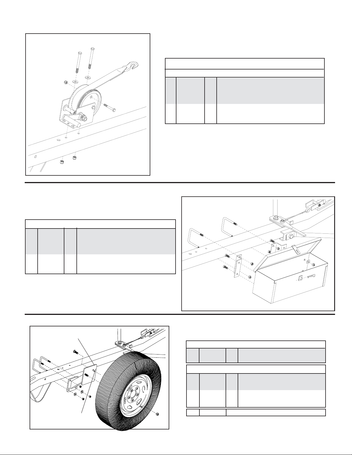
OPTIONAL WHEEL JACK
WHEEL JACK PARTS LIST
- KK2WJ 1 Optional Wheel Jack w/ hardware
Please order replacement parts by PART NO. and DESCRIPTION.
* All options may not mount on tow dolly simultaneously.*
OPTIONAL DEFLECTOR PARTS BREAKDOWN
REF. PART
NO. NO . QTY. DESCRIPTION
KK2DF Optional Deflector
1. 02055-25 2 Deflector Framework
2. 02592 4 3/8"-16UNC Nylon Insert Lock Nut
3. 02759 2 3/8"-16UNC Square U-Bolt (fits around 3" tube)
4. 00161-95 2 Lock Handle
5. 02054-25 1 Deflector Slide Mount
6. 00095 4 3/8"-16UNC x 3/4" lg. Square Head Set Screw
7. 02743-25 1 Deflector Upright Post
8. 02165 1 Deflector Lacing Cord (1/8" x 25 ft.)
9. 02161 1 Deflector Fabric
Please order replacement parts by PART NO. and DESCRIPTION.
OPTIONAL LIGHT BAR (KKLB) PARTS BREAKDOWN
1
OPTIONAL DEFLECTOR PARTS LIST
REF. PART
NO. NO. QTY. DESCRIPTION
KKLB Kar Kaddy Light Bar (complete)
1. 01772 2 Nylon Security Strap with hooks & tightener
2. 01857 1 Left Tail/ Brake and Signal Light w/Lenses
3. 01773 1 Brown Jumper Wire
4. 01886 4 Wire Holder (metal)
5. 02385-25 1 Light Bar Framework
6. 02386.25 2 Adjustable Light Bracket
7. 01856 1 Right Tail/ Brake and Signal Light w/Lenses
8. 02772 10 1/4"-20UNC Nylon Insert Locknut
9. 00092 6 1/4"-20UNC x 1/2" Hex Head Bolt
10. 01777-25 2 Light Bar "Z" Bracket
11. 01778 4 3" Suction Cup w/Bolt (#13)
12. 02198 1 Light Bar Wiring Harness (new style)
13. 00068 4 1/4"-20UNC x 3/4" Hex Head Bolt
14. 01911 - Large Red Lens
15. 01912 - Small Red Lens
16. 01890 - Clear Lens
Please order replacement parts by PART NO. and DESCRIPTION.
LIGHT BAR PARTS LIST
Page 21
8
6
8
9
9
1
4
9
7
2
8
9
8
12
6
4
5
4
3
7
2
8
3
5
4
9
10
11
1
13
11
16
13
COLOR CODE FOR WIRING HARNESS
WHITE Ground
BROWN Tail Lights, License Plate Lights,
Light Cluster Bar & Clearance Lights
YELLOW Left Turn and Stop
GREEN Right Turn and Stop
1
14
15
1
Page 22
OPTIONAL WINCH
5
PARTS LIST
REF.
6
7
1
7
4
3
NO. PART NO. QTY. DESCRIPTION
KK2W 1 Optional Winch
1. 04620 1 Winch Mechanism (1400 capacity)
- 04621 - Replacement Handle
3. 01738 1 Strap Assembly (includes strap & hook)
4. 02207 1 3/8"-16UNC x 3" Hex Hd. Bolt (gr.5)
5. 02769 2 3/8"-16UNC x 4" Hex Head Bolt (gr.5)
6. 00059 2 3/8" Flatwasher
7. 02592 3 3/8"-16UNC Nylon Insert Locknut
Please order replacement parts by PART NO. and DESCRIPTION.
* All options may not mount on tow dolly simultaneously.*
OPTIONAL TOOL BOX
PARTS LIST
KK2TB 1 Optional Tool Box
1. 00059 4 3/8" Flatwasher
2. 02592 8 3/8"-16UNC Nylon Insert Locknut
3. 01888-25 1 Tool Box
4. 00182 1 Small Hair Pin
5. 02742-25 2 Mounting "Z" Bracket
6. 00907 4 3/8"-16UNC x 1" Hex Head Bolt (gr.5)
7. 02759 2 3/8"-16UNC x 3" Square U-Bolt
Please order replacement parts by PART NO. and DESCRIPTION.
* All options may not mount on tow dolly simultaneously.*
OPTIONAL SPARE TIRE and MOUNT PARTS BREAKDOWN
Drive in stud here for
tire with rim #04173 X
(100mm bolt circle).
6
4
7
7
2
6
5
- KK8STBR 1 Optional Spare Tire and Rim
1. N/A 1 ST205/75R 14"x"C" BSW Radial Tire
2. 04367 1 6" x 14" Rim 115mm Bolt Circle
1
4
3
2
3
7
Drive in stud here for
tire with rim #04366
(115mm bolt circle).
8
2
1
5
* All options may not mount on tow dolly simultaneously.*
Page 22
KK6STM 1 Spare Tire Mounting Bracket
3. 02193-25 1 Spare Tire Bracket
4. 02917 1 Stud Bolt (12mm x 1.5)
5. 02933 2 Wheel Nut (12mm) Chrome
6. 02759 2 3/8"-16UNC Square U-Bolt
7. 00059 2 3/8" Flatwasher
8. 02592 4 3/8"-16UNC Nylon Insert Locknut
- KK6TC Optional Spare Tire Cover
Please order replacement parts by PART NO. & DESCRIP-
Page 23

NOTES
Page 23
Page 24

DETHMERS MFG. COMPANY
P.O. BOX 189
4010 320th St., BOYDEN, IA. 51234
PH: (712) 725-2311 FAX: (712) 725-2380
TOLL FREE: 1-800-54DEMCO (1-800-543-3626)
www.demco-products.com
Page 24
 Loading...