

Page 1

Find Freestanding Multimedia Book Pod Display @demco.com
Search:
1374049
Call 800.962.4463 or email custserv@demco.com
Page 2
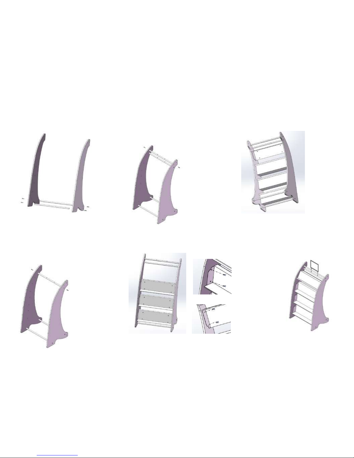
STEP 1
STEP 2
STEP 3
STEP 4
STEP 5
STEP 6
STEP 7
❶
❷ ❹ ❺
❸
❼
❻
❻
❼ ❼ ❸
❼
❼
❼
❽
Connect each of 2 Lower Support Rods (Part ❸)
to inside of each side panel (Part ❶ & ❷) with 2
bolts (Part ❼) in positions as shown.
ONLY thread each bolt to hand tight.
Connect the Upper Support Rods (Part ❹) to
inside of each side panel (Part ❶ & ❷) with 2
bolts (Part ❼) in position as shown.
ONLY thread each bolt to hand tight.
The Upper Support Rod has two holes on one
side
Connect the Sign Support Rod (Part ❺) to
inside of each side panel (Part ❶ & ❷) with 2
bolts (Part ❼) in position as shown.
ONLY thread each bolt to hand tight.
The Sign Support Rod has two holes on two
sides.
❽
Connect each of 3 Shelves (Part ❻) to inside of
each side panel (Part ❶ & ❷) with 4 Shelf
Bolts (Part ❽) in position as shown.
ONLY thread each bolt to hand tight.
Connect top Shelf (Part ❻) to inside of each
side panel (Part ❶ & ❷) with 4 Shelf Bolts
(Part ❽) in position as shown.
ONLY thread each bolt to hand tight.
Insert the Sign Frame (Part ❾) through both
sets of holes of Sign Support Rod (Part ❺) and
into the holes of the Upper Support Rod (Part
❹) in position as shown.
❾
With unit fully assembled, fully tighten all bolts
(Part ❼ and ❽) on left and right side using the
hex wrench.
Bookshelf
Display shelf
You can configure to each shelf to fit your needs. By rotating the shelf
it can be mounted as a Bookshelf or a Display shelf. The Bookshelf
would have the screws on the front side and the Display shelf would
have the screws on the back side as shown.
ASSEMBLY INSTRUCTIONS
Page 3

PARTS LIST
Description
Quantity
Image
❶
Left panel
1
❷
Right panel
1
❸
Lower Support Rods
2
❹
Upper Support Rod
1
❺
Sign Support Rod
1
❻
Shelf
4
❼
Bolt
8
❽
Shelf Bolt
16
❾
Sign Frame
1
Parts required for connecting two units. Must retain this hardware if
purchasing a second unit at a later date.
❿
Cam Post
2
⓫
Cam Insert
4
⓫
❿
With units fully assembled, insert the Cam Inserts (Part ⓫) into the
holes on the side panels as shown. Align each insert so that the opening
is visible through the hole on the back of the panels.
Insert each end of the Cam Post (Part ❿) through the hole on the back
of the panels. Turn the Cam Insert to secure the Cam Post using a screw
driver.
INSTRUCTIONS TO CONNECT TWO UNITS
(CREATE DOUBLE SIDED UNIT)
IMPORTANT NOTE:
DO NOT CONNECT
UNITS WITH CASTERS
MOUNTED TO UNITS
ASSEMBLY INSTRUCTIONS
 Loading...