

Page 1
DFBDFB
DFB
DFBDFB
01-21-94
AB20001
4040
40',
4040
ASSEMBLY
CALIBRATION
OPERATION
REPLACEMENT PARTS
45 45
45'
45 45
& 50 & 50
& 50'
& 50 & 50
OWNERS MANUALOWNERS MANUAL
OWNERS MANUAL
OWNERS MANUALOWNERS MANUAL
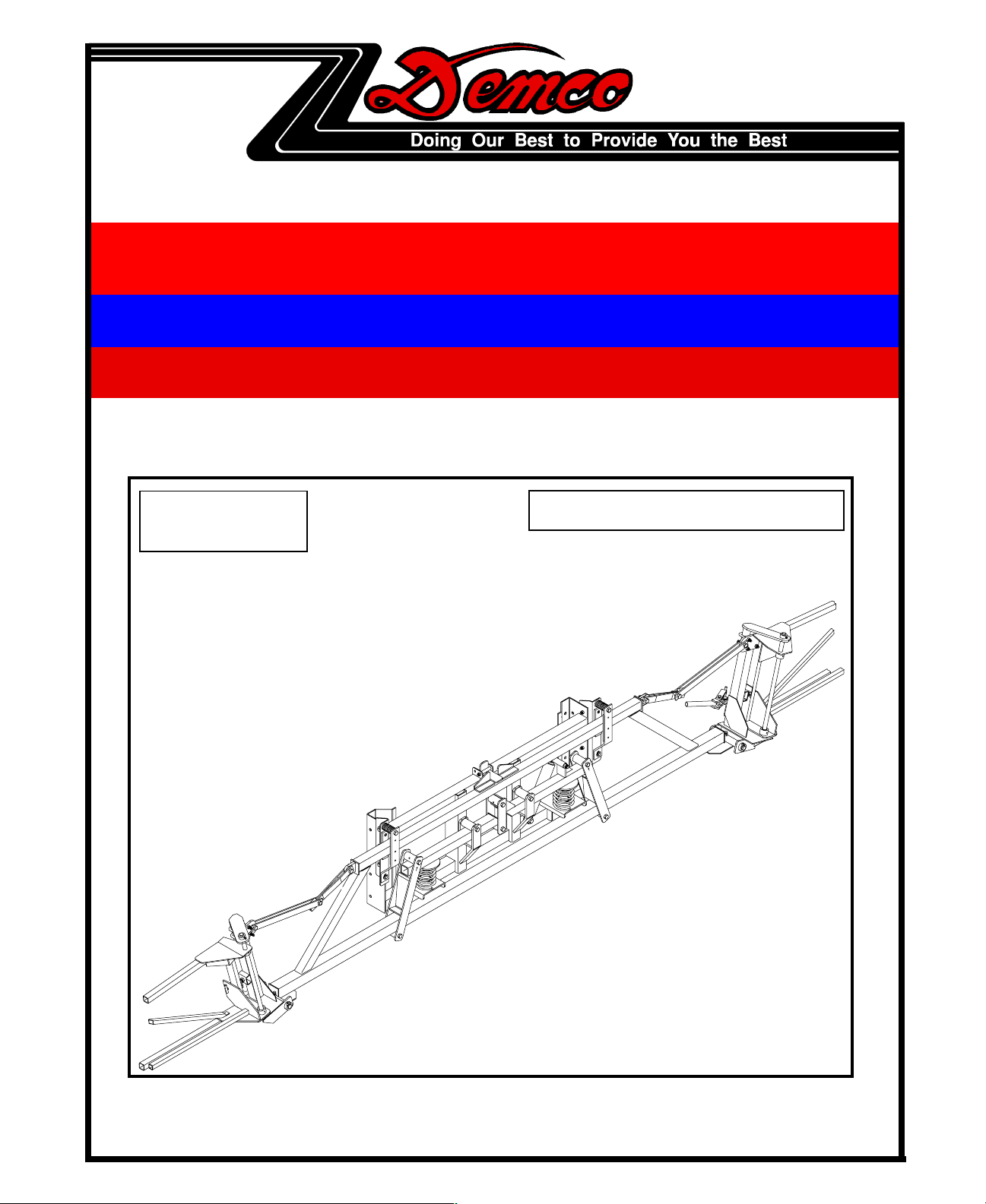
FLOTATION BOOM FLOTATION BOOM
FLOTATION BOOM
FLOTATION BOOM FLOTATION BOOM
READ complete manual CAREFULLY
BEFORE attempting operation.
DEMCO Dethmers Mfg. Co. P.O. Box 189 4010 320th Street Boyden, IA 51234
PH: (712) 725-2311 or (712) 725-2302 Toll Free: 1-800-543-3626 FAX: (712) 725-2380
Page 2

Thank you for purchasing a Demco boom. We
feel you have made a wise choice and hope you are
completely satisfied with your new flotation boom.
Your new Demco boom features the newest and
most up-to-date design of a boom it's type currently
marketed. DEMCO believes this to be a durable,
efficient, and easy to operate boom. If taken care
of properly it should serve you for many years.
If you have any questions regarding the applications of certain solutions or chemicals, contact your
chemical supplier and follow chemical manufacturer recommendations as well as all licensing and
use restrictions or regulations.
GENERAL INFORMATION
1. Unless otherwise specified, high-strength
(grade 5) (3 radial-line head markings) hex
head bolts are used throughout assembly of
this piece of equipment.
2. Whenever the terms "LEFT" and "RIGHT" are
used in this manual it means from a position
behind the machine and facing forward.
REMEMBER... Agricultural chemicals are dangerous. Know exactly what you're going to do and
what is going to happen before attempting to work
with these products. Improper selection or use can
injure people, animals, plants and soil. Always
wear protective clothing such as coveralls, goggles
and gloves when working with chemicals or the
boom.
3. When placing a parts order, refer to this manual
for proper part numbers and place order by part
number and description.
INDEX
Mounting the Center Section................................................................ Page 1
Mounting the Center Section With Hydraulic Height Adjust ................. Page 2
Mounting the Center Section With Manual Height Adjust..................... Page 3
Center Section Parts Breakdown and Parts List .................................. Page 4
Left Inner Wing Parts Breakdown and Parts List ................................. Page 5
Right Inner Wing Parts Breakdown and Parts List ............................... Page 6
Right and Left Outer Wing Parts Breakdown and Parts List ................ Page 7
Tip Placement and Nozzle Parts Breakdown and Parts List................ Page 8
Adjustment Procedures........................................................................ Page 9
Adjustment and Folding Procedures.................................................... Page 10
Maintenance and Lubrication............................................................... Page 11
Optional Hydraulic Wing Leveling and Wheel Tip Protector................. Page 12
Sprayer Calibration .............................................................................. Page 13
Sprayer Checklist................................................................................. Page 14
Page 3
Begin by attaching the center section of the boom to the sprayer. With the center section on the sprayer,
the boom can be assembled from the center section outward and final alignment made at that time.
4
2
4
2
3
3
1
3
3
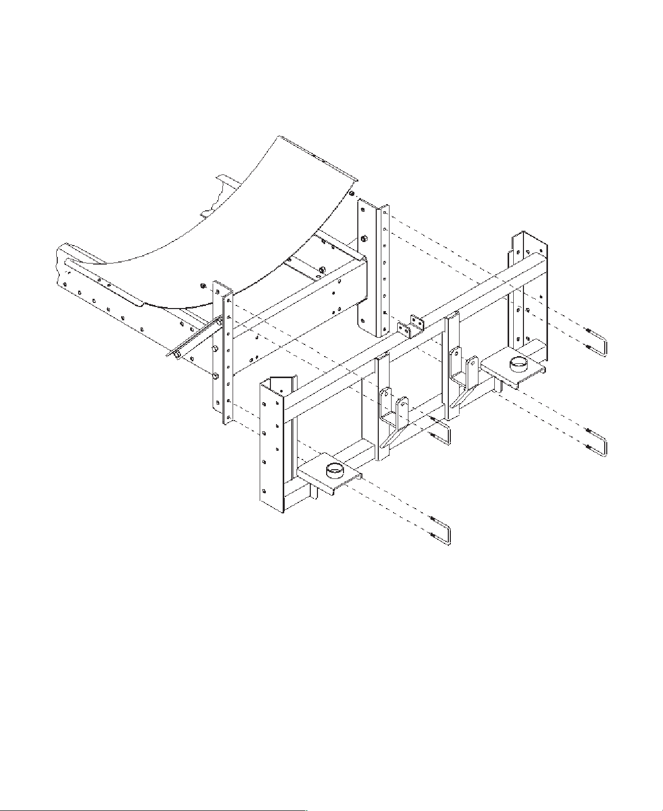
MOUNTING THE BOOM CENTER SECTION
Normal sprayer frame, without Height Adjuster. (Shown Above)
1. Mount the Boom Carrier Center Section (#1) to the Mounting Angles (#2) on the back of the sprayer
frame using four 3/8" x 2-1/2" square U-bolts (#3) and eight 3/8" nylon locknuts (#4). NOTE: The mounting
brackets (#2) may need to be turned in or out depending on sprayer frame width.
Page 1
Page 4
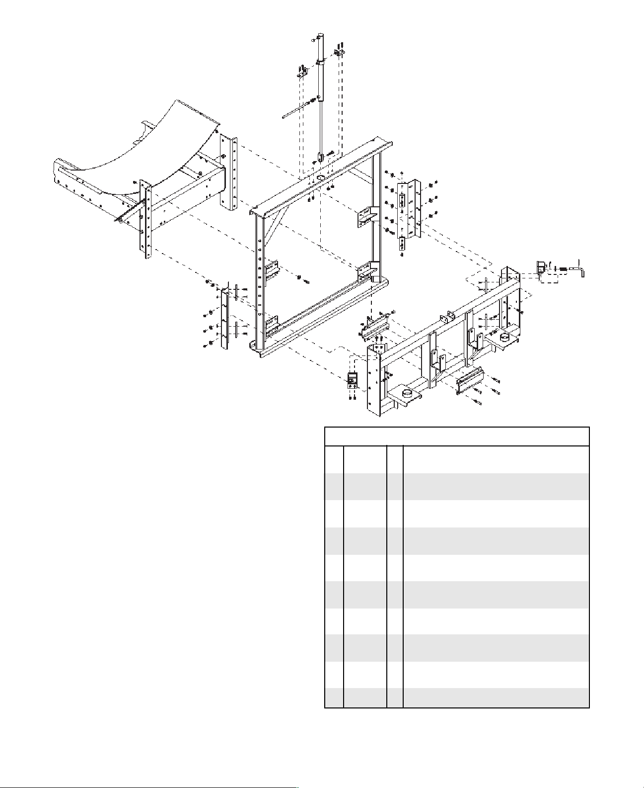
MOUNTING THE BOOM CENTER SECTION TO HYDRAULIC HEIGHT ADJUST
8
2
2
6
9
10
5
11
4
5
4
1
3
2
CAUTION -Do not operate height
adjust until final adjustments
have been made. Never stand on
or near the boom during height adjust operation.
3
5
17
16
15
3
5
17
3
5
16
15
14
ASSEMBLY INSTRUCTIONS
1. Mount the height adjust main frame (#1) to the boom mounting
brackets (#4) on the sprayer frame with eight 3/8" x 1-14" bolts (#2),
eight 3/8" flatwashers (#3) and eight 3/8" locknuts (#5). NOTE:
The mounting brackets (#4) may need to be turned in or out
depending on sprayer frame width.
2. Mount the lock pin brackets (#20) to the boom carrier (#13), using
four 1/2" x 1-1/4" bolts (#19) and four 1/2" locknuts (#11), make
sure the bolts are inserted in the right direction as shown above.
Place the lock pin (#25) & roll pin (#24) through the bracket (#20).
Insert the spring (#23) and 7/16" flatwasher (#22) to the inside of
the lock pin bracket and push the pin (#25) through. Secure the
lock pin assembly with cotter pin (#21) between the washer and
bracket. Make sure pin moves in and out freely and rotates down
into the "latch out" position easily.
3. Before mounting the boom carrier to the main frame assembly,
mount the UHMW wear pads (#15) to the boom carrier (#13) and
boom carrier brackets (#14) using sixteen 1/4" x 1" flathead screws
(#16) and sixteen 1/4" locknuts (#17).
4. Now place the boom carrier (#13) on to the main frame assembly
(#1) so that the lock pins are in the holes of the main frame. Loosely
mount the boom carrier brackets (#14) to the boom carrier (#13)
using eight 3/8" x 1-1/4" bolts (#2), six 3/8" x 1-1/2" bolts (#18),
fourteen 3/8" flatwashers (#3) and fourteen 3/8" locknuts (#5).
5. Slide the hydraulic cylinder (#7) clevis end down through the large
hole in the top of the main frame assembly (#1). The hole is slotted
so the cylinder inlet can be maneuvered through. Slide one
mounting ear bracket (#6) onto each peg on the cylinder, align over
holes in the main frame top and secure the mounting ears with four
3/8" x 1-1/4" bolts (#2) and four 3/8" locknuts (#5).
6. Attach the bottom lift bracket and back-up plate (#27&28) to the
center of the boom carrier (#13) with four 3/8" x 2-1/4" bolts (#26)
and four 3/8" locknuts (#5). The hole in the lift bracket (#28) is
offset and the hole must go towards the bottom for total adjustment. Compress the cylinder and attach the cylinder clevis to the
lift bracket with one 1/2" x 2" bolt (#12) through the 1/2" I.D. x 5/8"
lg. bushing (#29) and one 1/2" locknut. See page 9 for adjustment.
2
2
6
7
12
5
3
5
5
5
3
5
3
3
2
5
5
28
19
2
20
18
11
REF. PART
NO. NO. QTY. DESCRIPTION
1. 05601 1 Height Adjuster Main Frame
2. 00523 20 3/8"-16UNC x 1-1/4" Hex Head Bolt Gr.5
3. 00059 20 3/8" Flatwasher
4. ---- 2 Boom Mounting Brackets (not included)
5. 02592 30 3/8"-16UNC Nylon Insert Locknut
6. 05605 2 Top Cylinder Mounting Ear
7. 05600 1 Hydraulic Cylinder
8. 00288 1 Air Vent - hydraulic cylinder
9. 05661 1 3/8" MPT x 3/8" FPT Orifice Restrictor
10. 05013 1 26' Hydraulic Hose
11. 02178 5 1/2"-13UNC Nylon Insert Locknut
12. 01253 1 1/2"-13UNC x 2" Hex Head Bolt Gr.5
13. 03306 1 Boom Carrier
14. 03305 2 Boom Carrier Brackets
15. 02946 8 UHMW Wear Pad
16. 05732 16 1/4"-20UNC x 1" Slotted Flat Head
17. 02772 16 1/4"-20UNC Hex Nylon Insert Locknut
18. 00914 6 3/8"-16UNC x 1-1/2" Hex Head Bolt Gr.5
19. 00967 4 1/2"-13UNC x 1-1/4" Hex Head Bolt Gr.5
20. 03340 2 Lock Pin Bracket
21. 02363 2 5/32" x 1/14" Cotter Pin
22. 00205 2 7/16" Flatwasher
23. 02208 2 Lock Spring
24. 03099 2 Roll Pin (3/16" x 1")
25. 03342 2 Lock Pin
26. 02494 4 3/8"-16UNC x 2-1/-4" Hex Head Bolt Gr.5
27. 05604 1 Bottom Lift Back Plate
28. 05603 1 Bottom Lift Bracket
29. 01839 1 1/2" I.D. x 5/8" lg. Spacer
Please order replacement parts by PART NO. and DESCRIPTION.
(DFBHAH OPTION)
17
14
5
3
15
16
5
3
15
16
16
29
15
16
27
13
26
PARTS LIST
15
18
18
20
2
13
26
21
22
23
24
25
NOTE: Use CAUTION when adjusting height. Make sure all air is
bled from the line before initial trial.
Page 2
Page 5
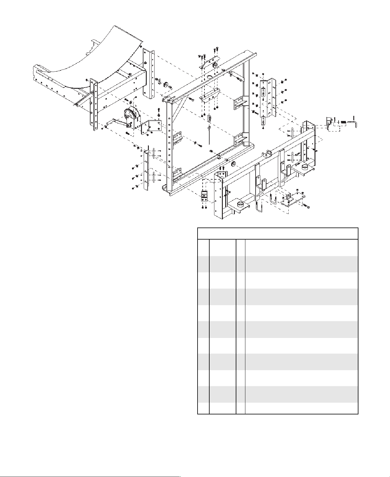
MOUNTING THE BOOM CENTER SECTION TO MANUAL HEIGHT ADJUST
(DFBHA OPTION)
5
4
9
5
25
27
26
2
3
4
22
20
8
21
5
2
3
18
16
17
5
15
3
5
18
17
16
5
3
ASSEMBLY INSTRUCTIONS
1. Mount the height adjust main frame (#1) to the boom mounting
brackets (#4) on the sprayer frame with eight 3/8" x 1-1/4" bolts
(#2), eight 3/8" flatwashers (#3) and eight 3/8" locknuts (#5).
NOTE: The mounting brackets (#4) may need to be turned in or out
depending on sprayer frame width.
2. Mount the lock pin brackets (#6) to the boom carrier (#7) using four
1/2" x 1-1/4" bolts (#8) and four 1/2" locknuts (#9) make sure these
bolts are inserted in the right direction as shown above. Place the
lock pin (#14) & roll pin (#13) through the brackets (#6). Insert the
lock spring (#12) and 7/16" flatwasher (#11) to the inside of the lock
pin bracket and push the pin (#14) through. Secure the lock pin
assembly with cotter pin (#10) between the washer and bracket.
Make sure pin moves in and out freely and rotates down into the
"latch out" position easily.
3. Before mounting the boom carrier to the main frame assembly,
mount the UHMW wear pads (#16) to the boom carrier (#7) and
boom carrier brackets (#15) using sixteen 1/4" x 1" flathead screws
(#17) and sixteen 1/4" nuts (#18).
4. Now place the boom carrier (#7) on to the main frame assembly
(#1) so that the lock pins are in the holes of the main frame. Loosely
mount the boom carrier brackets (#15) to the boom carrier (#7)
using eight 3/8" x 1-1/4" bolts (#2), six 3/8" x 1-1/2" bolts (#19),
fourteen 3/8" flatwashers (#3) and fourteen 3/8" locknuts (#5).
5. Attach the two top pulley mounts (#23) to the main frame (#1) as
shown using four 3/8" x 1-1/2" bolts (#2) and four 3/8" locknuts (#5).
Attach the top pulley (#27), spacer (#26) and cable retainer bracket
(#25) with 1/2" x 1-3/4" bolt (#24) and 1/2" locknut (#9). Assemble
the pulley on the top left side of the height adjuster main frame.
Adjust cable retainer brackets (#25) to always keep the cable in the
pulley grove even when there is no tension on the cable.
6. Attach the bottom pulley mount (#28) to the center of the boom
carrier (#7) using two 3/8" x 2-1/2" sq. U-bolts (#29) and two 3/8"
locknuts (#5). Attach the pulley (#27) to the bottom pulley mount
(#28) ear, using one 1/2" x 1-3/4" bolt (#24), cable retainer bracket
(#25), and spacer (#26), then secure with a 1/2" locknut (#9). Align
this bracket so the cable runs straight down from the top, around
the bottom pulley and back up to the rapidlink (#30).
24
23
2
2
9
27
26
25
23
5
5
30
31
24
1
18
15
5
3
5
3
16
17
5
3
3
2
16
17
5
3
5
3
10
6
16
11
17
3
9
2
25
26
27
8
2
6
9
19
29
7
29
17
16
2
19
19
7
5
5
28
24
PARTS LIST
REF. PART
NO. NO. QTY. DESCRIPTION
1. 05601 1 Height Adjuster Main Frame
2. 00523 23 3/8"-16UNC x 1-1/4" Hex Head Bolt Gr. 5
3. 00059 23 3/8" Flatwasher
4. ---- 2 Boom Mounting Brackets (not included)
5. 02592 33 3/8"-16UNC Nylon Insert Locknut
6. 03340 2 Lock Pin Bracket
7. 03306 1 Boom Carrier
8. 00967 6 1/2"-13UNC x 1-1/4" Hex Head Bolt Gr.5
9. 02178 7 1/2"-13UNC Nylon Insert Locknut
10. 02363 2 5/32" x 1/14" Cotter Pin
11. 00205 2 7/16" Flatwasher
12. 02208 2 Lock Spring
13. 03099 2 Roll Pin (3/16" x 1")
14. 03342 2 Lock Pin
15. 03305 2 Boom Carrier Brackets
16. 02946 8 UHMW Wear Pad
17. 05732 16 1/4"-20UNC x 1" Slotted Flat Head
18. 00062 16 1/4"-20UNC Hex Nut
19. 00914 6 3/8"-16UNC x 1-1/2" Hex Head Bolt Gr.5
20. 03345 1 Winch Mount Bracket
21. 00084 2 1/2" Lockwasher
22. 04967 1 Winch w/ disc brake - 1200 lb. cap. (w/ handle)
- 04971 1 Replacement Handle only
23. 05607 2 Top Pulley Mount
24. 00482 3 1/2"-13UNC x 1-3/4" Hex Head Bolt Gr.5
25. 01838 3 Cable Retainer Bracket
26. 01839 3 1/2" I.D. x 5/8" lg. Spacer
27. 01840 3 Pulley
28. 05609 1 Bottom Pulley Mount
29. 01887 2 3/8"-16UNC x 2-1/2" U-bolt
30. 04819 1 5/16" Rapid Link
31. 05611 1 3/16" Aircraft Cable x 20' lg. with thimble
Please order replacement parts by PART NO. and DESCRIPTION.
7. Attach the winch mounting bracket (#20) to the height adjust main
frame (#1) using two 1/2" x 1-1/4 bolts (#8) and two 1/2" lockwashers
(#21). Mount the winch (#22) to the winch mounting bracket (#20),
using three 3/8" x 1-1/4" bolts (#2), three 3/8" flatwashers (#3) and
three 3/8" locknuts (#5).
13
12
14
Page 3
Page 6

19
19
10
20
20
13
15
CENTER SECTION BOOM CARRIER BREAKDOWN
10
5
21
15
5
11
6
20
20
20
14
23
19
15
16
16
10
5
8
3
12
7
9
10
4
9
24
18
15
18
23
9
9
9
22
20
19
5
30
32
33
31
29
Note: This bracket must be 5" off center
in either direction.
9
21
19
17
17
21
25
28
26
21
27
21
10
10
10
1
21
30
21
11
5
10
11
6
10
5
2
5
10
20
21
15
34
18
4
9
10
9
5
PARTS LIST
REF. PART
NO. NO. QTY. DESCRIPTION
1. 03306 1 Boom Carrier
2. 03309 1 Boom Carrier Left Floater
3. 03310 1 Boom Carrier Right Floater
4. 03330 2 Spring
5. 03313 8 Pivot Bushing (2-7/8" long)
6. 03311 2 Linkage Plate
7. 03312 2 Auto-Level Linkage
8. 03331 1 Shock
9. 01338 8 1/2"-13UNC x 4-1/2" Hex Head Bolt Gr.5
10. 02178 14 1/2"-13UNC Nylon Insert Locknut
11. 01975 3 1/2"-13UNC x 5" Hex Head Bolt Gr.5
12. 04073 1 1/2"-13UNC x 3" Hex Head Bolt Gr.5
13. 03307 1 Left Auto-Level Sway Control Bracket
14. 03308 1 Right Auto-Level Sway Control Bracket
15. 03324 4 UHMW Wear Pad
16. 05732 4 1/4"-20UNC x 1" Slotted Flat Head
17. 02772 4 1/4"-20UNC Nylon Insert Locknut
18. 00516 4 1/4"-20UNC x 3/4" Slotted Flat Head
19. 00523 8 3/8"-16UNC x 1-1/4" Hex Head Bolt Gr.5
20. 00059 16 3/8" Flatwasher
21. 02592 23 3/8"-16UNC Nylon Insert Locknut
22. 03314 1 Center Section
23. 02945 2 Auto-Level Sway Guide
24. 01348 2 Spring (1" O.D. x 3" long)
25. 03317 1 Auto-Level Latch
26. 01903 1 3/8"-16UNC x 3-1/2" Hex Head Bolt Gr.5
27. 00199 1 Lock Pin (3/8" O.D. x 3-1/2" lg.)
28. 00182 1 1/8" Small Hair Pin
29. 03334 3 Center Nozzle Tube Mounting Plate
30. 01887 7 3/8"-16UNC x 2-1/2" Square U-bolt
31. 00909 3 5/16"-18UNC x 1-1/4" Sq. U-bolt
32. 03333 1 Center Nozzle Mounting Tube
33. 02802 6 5/16"-18UNC Nylon Insert Locknut
34. 03399 2 Bottom Center Support Bracket
Please order replacement parts by PART NO. and DESCRIPTION.
1. Begin by referring to the boom carrier (#1) mounting to the sprayer
ASSEMBLY INSTRUCTIONS
frame (page 1) or mounting to the height adjust (pages 2 & 3). After the
boom carrier is mounted begin assembling the center section.
2. Mount the left floater tube (#2) to the boom carrier (#1) using one 1/2"
x 5" bolt (#11), pivot bushing (#5), and one 1/2" locknut (#10). Next
mount the right floater tube (#3) to the boom carrier (#1) using one 1/
2" x 5" bolt (#11), one pivot bushing (#5), and one 1/2" locknut (#10).
3. Place the auto-level springs (#4) between the left and right floater (#2
& 3) and the boom carrier (#1). Attach the left floater (#2) and right
floater (#3) using two linkage plates (#6), two pivot bushings (#5), two
1/2" x 4-1/2" bolts (#9), and two 1/2" locknuts (#10).
4. Now mount the shock (#8) to the right floater (#3) using one 1/2" x 5"
bolt (#11) and one 1/2" locknut (#10). Mount the opposite end of the
shock to the boom carrier (#1) using one 1/2" x 3" bolt (#12) and one
1/2" locknut (#10).
5. Mount the auto-level linkage (#7) to the left floater (#2) using one 1/2"
x 4-1/2" bolt (#9), one pivot bushing (#5), and one 1/2" locknut (#10).
NOTE: Make sure the arrows on the linkage are up as shown above.
Mount the auto-level linkage (#7) to the right floater (#3) using one 1/
2" x 4-1/2" bolt (#9), one pivot bushing (#5), and one 1/2" locknut (#10).
6. Mount the center section onto the boom center section (#22). Secure
the linkages (#7) on the right and left to the bottom of the boom center
section (#22) using two 1/2" x 4-1/2" bolts (#9), two pivot bushings (#5)
and two 1/2" locknuts (#10).
7. Attach the left and right auto-level sway control brackets (#13 & 14) to
the boom carrier (#1) using six 3/8" x 1-1/4" bolts (#19), six 3/8"
flatwashers (#20) and six 3/8" locknuts (#21). Next mount the UHMW
wear pads (#15) to the sway control brackets (#13 & 14) using four 1/
4" x 1" slotted flat head screws (#16) and four 1/4" locknuts (#17).
Assemble the UHMW wear pads (#15) to the auto-level sway control
guides (#23) and the bottom center support bracket (#34) using eight
1/4" x 3/4" slotted flat head screws (#18). Mount the sway control
guides (#23) with UHMW wear pads to the right and left sway control
brackets (#13 & 14) using two 3/8" x 1-1/4" bolts (#19), two 3/8"
flatwashers (#20) and two 3/8" locknuts (#21). Bolt the top of the sway
control guides and sway control brackets together using two 1/2" x 41/2" bolts (#9), two springs (#24) and two 1/2" locknuts (#10). Mount
the bottom center support bracket (#34), with UHMW, to bottom tube
of boom carrier (#1) using four 3/8" x 2-1/2" square u-bolts (#30), eight
3/8" flatwashers (#20) and eight 3/8" nylon insert locknuts (#21).
8. Assemble the center boom nozzle mounting plates (#29) to the center
section (#22) as shown using three 3/8" x 2-1/2" sq. U-bolts (#30) and
six 3/8" locknuts (#21). Next mount the center nozzle tube (#32) to the
mounting plates (#29) using three 5/16" x 1-1/2" sq. U-bolts (#31) and
six 5/16" locknuts (#33).
Page 4
Page 7

LEFT INNER WING PARTS BREAKDOWN
15
28
24
25
19
27
26
21
22
20
12
9
10
8
9
6
7
9
7
1
26
23
14
31
33
30
27
27
32
33
NOTE: To attach the gusset
35
36
34
plate (#36) follow step
7 on page 7.
ASSEMBLY INSTRUCTIONS
1. Attach the upper offset linkage (#6) to center section (#1) using
one 1/2" x 2" bolt (#7), bushing (#8) and one 1/2" locknut (#9).
2. Next attach the lower linkage bracket (#10) to the upper offset
linkage (#6) using one 1/2" x 2" bolts (#7) and one 1/2" locknut
(#9).
3. Mount the left center hinge (#2) to the center section (#1). Secure
with pin (#3), 3/4" machine washer (#16), 3/8" x 3/4" setscrew (#5)
and 3/8" jam nut (#4).
4. Bolt the linkage mounting plate (#11) to the left center hinge (#2)
as shown using two 3/8" x 2-1/2" U-bolts (#12) and four 3/8"
locknuts (#13). Bolt the lower linkage bracket (#10) to the linkage
mounting plate (#11) using one 1/2" x 2" bolt (#7), bushing (#8),
and one 1/2" locknut (#9).
5. Attach the left inner wing (#14) to the left center hinge (#2) with the
3/4" machine washer (#16) between the wing and hinge, using the
center hinge pin (#15). Secure with two 5/16" x 1/2" setscrews
(#17).
6. Insert the 1/2" x 1-1/2" bolt (#18) and 1/2" nut (#19) into the center
hinge (#2) as shown above.
7. Assemble the wing latch handle (#20) to the center hinge (#2)
using the 7/16" clevis pin (#21), 3/8" flatwasher (#22) and secure
with 5/32" x 1" cotter pin (#23). Next attach the wing latch channel
(#24) to the wing latch handle (#20) using one 5/16" x 2-1/2" bolt
(#25), two 5/16" flatwashers (#26), and one 5/16" locknut (#27).
Next screw the tee bolt (#28) into the wing latch channel (#24) and
secure with 1/2" jam nut (#19) on back side.
8. Bolt the wing storage bracket (#30) to the left wing approximately
23" from latch plate on the left wing, using two 5/16" x 2" sq. U-bolt
(#35) and four 5/16" locknuts (#27).
Page 5
11
7
5
4
13
8
17
2
29
19
29
16
16
18
3
29
17
16
PARTS LIST
REF. PART
NO. NO. QTY. DESCRIPTION
1. 03314 1 Center Section
2. 03315 1 Left Hinge
3. 03319 1 Center Hinge Pin
4. 04886 1 3/8"-16UNC Jam Nut
5. 00095 1 3/8"-16UNC x 3/4" Square Head Setscrew
6. 00171 1 Upper Offset Linkage Bracket
7. 01253 3 1/2"-13UNC x 2" Hex Head Bolt Gr.5
8. 02491 2 Bushing (3/4" O.D. x 1/2" I.D. x 1/2" lg.)
9. 02178 3 1/2"-13UNC Nylon Insert Locknut
10. 00170 1 Lower Linkage Bracket
11. 03318 1 Linkage Mounting Plate
12. 05294 2 3/8"-16UNC x 2-1/8" Square U-bolt
13. 02592 4 3/8"-16UNC Nylon Insert Locknut
14. 03322 1 Left Inner Wing
15. 03321 1 Inner Hinge Pin (3/4" x 20")
16. 02534 3 3/4" x 14 Ga. Machine Washer
17. 00091 2 5/16"-18UNC x 1/2" Square Head Set Screw
18. 01254 1 1/2"-13UNC x 1-1/2" Hex Head Bolt Gr.5
19. 00640 2 1/2"-13UNC Jam Nut
20. 05309 1 Wing Latch Handle
21. 00080 1 7/16" x 1-1/4" lg. Clevis Pin
22. 00059 1 3/8" Flatwasher
23. 00185 1 5/32" x 1" lg. Cotter Pin
24. 05310 1 Wing Latch Channel
25. 04221 1 5/16"-18UNC x 2-1/2" Hex Head Bolt Gr.5
26. 00004 2 5/16" Flatwasher
27. 02802 3 5/16"-18UNC Nylon Insert Locknut
28. 03320 1 Latch Bolt
29. 04642 4 Zerk
30. 03335 1 Storage Bracket
31. 04822 3 1/4"-20UNC x 1-1/16" Square U-bolt
32. 00199 1 3/8" Dia. x 3-1/2" lg. Lock Pin
33. 00182 1 1/8" Small Hair Pin
34. 02772 6 1/4"-20UNC Nylon Insert Locknut
35. 00909 1 5/16"-18UNC x 1-1/4" Square U-bolt
36. 03537 1 Gusset Plate
Please order replacement parts by PART NO. and DESCRIPTION.
Page 8

RIGHT INNER WING PARTS BREAKDOWN
12
28
31
27
32
35
26
27
36
37
26
34
27
25
19
20
27
24
21
22
26
9
23
10
9
9
6
7
29
8
7
1
5
4
16
16
8
7
2
29
33
ASSEMBLY INSTRUCTIONS
1. Attach the upper offset linkage (#6) to center section (#1) using
one 1/2" x 1-3/4" bolt (#7), bushing (#8) and one 1/2" locknut (#9).
2. Next attach the lower linkage bracket (#10) to the upper offset
linkage (#6) using one 1/2" x 1-3/4" bolts (#7) and one 1/2" locknut
(#9).
3. Mount the right center hinge (#2) to the center section (#1).
Secure with pin (#3), 3/4" machine washer (#16) and 3/8" x 3/4"
setscrew (#5) and 3/8" nut (#4).
4. Bolt the linkage mounting plate (#11) to the right center hinge (#2)
as shown using two 3/8" x 2-1/2" U-bolts (#12) and four 3/8"
locknuts (#13). Bolt the lower linkage bracket (#10) to the linkage
mounting plate (#11) using one 1/2" x 1-3/4" bolt (#7), bushing
(#8), and one 1/2" locknut (#9).
5. Attach the right inner wing (#14) to the right center hinge (#2) with
the 3/4" machine washer (#16) between the wing and hinge, using
the center hinge pin (#15). Secure with two 1/4" x 1/4" setscrews
(#17).
6. Insert the 1/2" x 1-1/2" bolt (#18) and 1/2" nut (#19) into the center
hinge (#2) as shown above.
7. Assemble the wing latch handle (#20) to the center hinge (#2)
using the 7/16" clevis pin (#21), 3/8" flatwasher (#22) and secure
with 5/32" x 1" cotter pin (#23). Next attach the wing latch channel
(#24) to the wing latch handle (#20) using one 5/16" x 2-1/2" bolt
(#25), two 5/16" flatwashers (#26) and one 5/16" locknut (#27).
Next screw the tee bolt (#28) into the wing latch channel (#24) and
secure with 1/2" jam nut (#19) on back side.
8. Bolt the wing storage bracket (#30) to the right wing approximately
23" from latch plate on the left wing, using two 5/16" x 1-1/4" sq.
U-bolt (#31) and four 5/16" locknuts (#27).
9. Mount all brackets in this step loosely in locations shown. When
boom is complete, fold and adjust brackets to support the boom in
the folded positon. Mount the wing storage upright (#32) to the top
of the center section (#1) using two 5/16" x 2-1/2" L-bolts (#33) and
four 5/16" locknuts (#27). Attach the storage cross tube (#34) to
the storage upright (#32) using two 5/16" x 1-1/4" square u-bolts
(#31), four 5/16" flatwashers (#26) and 5/16" nylon insert locknuts
(#27). Place the 1-1/4" Cap Plug (#35) in the end of the upright
(#32).
Page 6
15
36
14
30
27
17
29
27
37
NOTE: To attach the gusset
plates (#38) follow step
31
31
7 on page 7.
11
13
18
19
16
29
17
3
PARTS LIST
REF. PART
NO. NO. QTY. DESCRIPTION
1. 03314 1 Center Section
2. 03316 1 Right Hinge
3. 03319 1 Center Hinge Pin
4. 04886 1 3/8"-16UNC Jam Nut
5. 00095 1 3/8"-16UNC x 3/4" Square Head Setscrew
6. 00171 1 Upper Offset Linkage Bracket
7. 01252 3 1/2"-13UNC x 2" Hex Head Bolt Gr.5
8. 02491 2 Bushing (3/4" O.D. x 1/2" I.D. x 5/8" lg.)
9. 02178 3 1/2"-13UNC Nylon Insert Locknut
10. 00170 1 Lower Linkage Bracket
11. 03318 1 Linkage Mounting Plate
12. 05294 2 3/8"-16UNC x 2-1/8" Square U-bolt
13. 02592 4 3/8"-16UNC Nylon Insert Locknut
14. 03323 1 Right Inner Wing
15. 03321 1 Inner Hinge Pin
16. 02534 3 3/4" x 14 Ga. Machine Washer
17. 00091 2 5/16"-18UNC x 1/2" Square Head Set Screw
18. 01254 1 1/2"-13UNC x 1-1/2" Hex Head Bolt Gr.5
19. 00640 2 1/2"-13UNC Jam Nut
20. 05309 1 Wing Latch Handle
21. 00080 1 7/16" x 1-1/4" lg. Clevis Pin
22. 00059 1 3/8" Flatwasher
23. 00185 1 5/32" x 1" lg. Cotter Pin
24. 05310 1 Wing Latch Channel
25. 04221 1 5/16"-18UNC x 2-1/2" Hex Head Bolt Gr.5
26. 00004 6 5/16" Flatwasher
27. 02802 15 5/16"-18UNC Nylon Insert Locknut
28. 03320 1 Latch Bolt
29. 04642 4 Zerk
30. 03338 1 Storage Bracket
31. 00909 5 5/16"-18UNC x 1-1/4" Sq. U-bolt
32. 03437 1 Storage Upright Bracket
33. 05818 2 5/16"-18UNC x 2-1/2" L-bolt
34. 03438 1 Storage Cross Tube Bracket
35. 05188 5 1-1/4" Square Cap Plug
- 04739 2 1" Square Cap Plug
36. 00199 2 Lock Pin (3/8" O.D. x 3-1/2" lg.)
37. 00182 2 1/8" Small Hairpin
38. 03537 1 Gusset Plate
39. 04822 1 1/4"-20UNC x 1-1/16" Square U-bolt
40. 02722 2 1/4"-20UNC Nylon Insert Locknut
Please order replacement parts by PART NO. and DESCRIPTION.
39
27
38
40
Page 9

RIGHT AND LEFT OUTER WING PARTS BREAKDOWN
21
24
14
4
10
7
8
9
29
3
32
33
27
23
2
26
31
31
23
27
PARTS LIST
REF. PART
NO. NO. QTY. DESCRIPTION
1. 03322 1 Left Inner Wing
2. 03323 1 Right Inner Wing
3. 03328 2 Right and Left Outer Wing
4. 03326 2 Breakaway Pin
5. 03325 2 Outer Breakaway Hinge
6. 03329 2 Outer Hinge Pin
7. 04051 4 5/8"-11UNC x 1-1/2" Hex Head Bolt Gr.5
8. 00085 4 1/2" Flatwasher
9. 00490 4 Breakaway Bearing
10. 03327 2 Lock Collar
11. 05318 2 Spring
12. 00694 6 1/4"-20UNC x 1/2" Square Head Set Screw
13. 02772 8 1/4"-20UNC Nylon Insert Locknut
14. 00640 6 1/2"-13UNC Jam Nut
15. 00967 4 1/2"-13UNC x 1-1/4" Hex Head Bolt Gr.5
16. 02178 2 1/2"-13UNC Nylon Insert Locknut
17. 05309 2 Wing Latch Handle
18. 00080 2 7/16" x 1-1/4" lg. Clevis Pin
19. 00059 2 3/8" Flatwasher
20. 00185 2 5/32" x 1" lg. Cotter Pin
21. 05310 2 Wing Latch Channel
22. 04221 2 5/16"-18UNC x 2-1/2" Hex Head Bolt Gr.5
23. 02802 18 5/16"-18UNC Nylon Insert Locknut
24. 03320 2 Latch Bolt
25. 00004 4 5/16" Flatwasher
26. 05297 2 Tip Protector
27. 00909 8 5/16"-18UNC x 1-1/4" Square U-bolt
28. 03439 1 Storage Bracket
29. 04642 4 Zerk
30. 05319 2 Tip Offset Bracket
31. 04822 4 1/4"-20UNC x 1-1/16" Square U-bolt
32. 05171 2 Wing Tip Extension for 50' boom (optional)
33. 00209 2 3/8"-16UNC x 1" Square Head Set Screw
34. 00199 1 Lock Pin (3/8"O.D. x 3-1/2" lg.)
35. 00182 1 1/8" Small Hairpin
36. 03537 2 Gusset Plate
36
13
Please order replacement parts by PART NO. and DESCRIPTION.
5
20
12
16
23
27
22
31
21
23
36
13
4
7
10
8
12
29
11
8
29
9
9
24
14
22
23
9
13
12
11
18
19
17
1
25
27
29
20
6
15
14
5
12
8
30
16
25
23
6
7
12
29
29
27
25
14
15
18
19
30
34
25
23
17
28
35
ASSEMBLY INSTRUCTIONS
1. Attach the outer wing (#3) to the breakaway hinge (#5). Place
bearings (#9), 1/2" flatwashers (#8) and 1/2" x 1-3/4" bolts (#7) to
the outer wing (#3). Slide outer wing (#3) on to the breakaway
hinge (#5). Insert breakaway hinge pin (#4) through the outer
wing top bushing through the breakaway hinge top bushing,
through the lock collar (#10), through the 1/2" flatwasher, spring
(#11) and 1/2" flatwasher (#8), through the bottom bushing on the
outer wing and through the breakaway hinge, place 1/2" locknut
(#16) on the hinge pin (#4) do not tighten. Tighten the 1/4" x
1/2" sq. head setscrew (#12) on the lock collar (#10), now tighten
the 1/2" locknut (#16) to compress breakaway spring, the spring
should be compressed to about 3-1/4". Do not over compress.
2. Assemble the outer wing and breakaway hinge to the inner left
and right wing (#1 & 2). Insert hinge pin (#6) through the bushings
and secure using 1/4" x 1/2" square head set screw (#12).
3. Insert four 1/2" x 1-1/4" bolts (#15) and four 1/2" jam nut (#14) into
the inner left and right wing (#1 & 2).
4. Assemble the wing latch handle (#17) to the inner right and left
wing (#1 & 2) using the 7/16" clevis pin (#18), 3/8" flatwasher (#19)
and secure with 5/32" x 1" cotter pin (#20). Next attach the wing
latch channel (#21) to the wing latch handle (#17) using one 5/16"
x 2-1/2" bolt (#22), two 5/16" flatwashers (#25) and one 5/16"
locknut (#23). Next screw the tee bolt (#24) into the wing latch
channel (#21) and secure with 1/2" nut (#14) on back side.
5. Bolt the wing storage bracket (#28) to the right inner wing
approximately 30" from latch plate, using two 1/4" x 1-1/16" sq. Ubolt (#31) and four 1/4" locknuts (#13).
6. Bolt the wing tip protector (#26) to the outer right and left wing (#3)
approximately 17" from wing tip. Secure using four 5/16" x
1-3/8" sq. U-bolts (#27) and eight 5/16" locknuts (#23).
7. Attach the gusset plate to the bottom wing tube and the nozzle
tube, center them as close as possible, between the hinge points
and the welded in gusset. Attach them using one 5/16" x 1-1/4"
Square U-bolt (#27), two 5/16" Locknuts (#23), one 1/4" x 1-1/16"
Square U-bolt (#31) and two 1/4" Locknuts (#13).
3
7
Page 7
Page 10

TIP PLACEMENT
1. Marking location of boom clamps: Mark the clamp
locations by starting at the center of the center boom section.
From this mark, locate 20 inch spaces to both ends of the
boom.
2. Fasten preassembled boom lines: Fasten the boom
clamps (#3) on the boom so the sprayer tip will be on the back
side of the boom. The wing extensions for the 60 foot boom are
1 inch tubing. Therefore, this boom will have two size clamps.
NOTE: 40' Boom ......25 Tips
45' Boom ......27 Tips
50' Boom ......31 Tips(w/ 1" Ext.Tube)
BASIC PLUMBING PARTS LIST
REF. PART
NO. NO. DESCRIPTION
- 340RB 3/4" Rubber Hose
- B12H 3/4" Gear Clamp
- NHT11 Nylon Hose Ties
Please order replacement parts by PART NO. and DESCRIPTION.
Feeder Line Routing and Tip Placement for Outer HingeFeeder Line Routing and Tip Placement for Inner Hinge
CONVENTIONAL NOZZLES AND BOOM CLAMPS
1-1/4" BOOM CLAMP PARTS LIST
REF. PART
4
1
3
3
2
6
*
7
5
NO. NO. DESCRIPTION
- B11 114 1-1/4" Boom Clamp Assembly
1. 00068 1/4"-20UNC x 3/4" Hex Head Bolt
2. 00062 1/4"-20UNC Hex Nut
3. 00337 1-1/4" Boom Clamp
- 00338 1" Boom Clamp
3/4" NOZZLE PARTS LIST
REF. PART
NO. NO. DESCRIPTION
4. NTL34 3/4" Nozzle Tee
5. NTT34 3/4" Nozzle Elbow
6. B12 Nut
* ------ Tip (specify tip size) (not included)
7. 8027 11/16" FPS Cap
Please order replacement parts by PART NO. and DESCRIPTION.
DRIP FREE NOZZLES AND BOOM CLAMPS
1
3
3
2
9
14
*
10
13
8
12
11
REF. PART
NO. NO. DESCRIPTION
- DF34NTL 3/4" Nozzle Elbow & Check Valve Assembly
- DF34NTT 3/4" Nozzle Tee & Check Valve Assembly
8. DF34T 3/4" Nozzle Tee
9. DF34E 3/4" Nozzle Elbow
10. DFB12 Nut
11. DFCP Spring Retainer Cap Assembly
12. DFDV Diaphragm (viton)
13. DFFD Floodjet Cap (red)
- DFFT Flat Cap (yellow)
14. DFGE Gasket (EPDM)
* ------ Tip (specify tip size) (not included)
Please order replacement parts by PART NO. and DESCRIPTION.
3/4" NOZZLE PARTS LIST
Page 8
Page 11

ADJUSTMENT PROCEDURES
After the boom is completely assembled and before
attempting to fold the boom for the first time, the
boom should be adjusted so it lays straight both
horizontally and vertically. There are several adjustment points built into the boom for this purpose.
1.All adjustments must be done with the boom
unfolded and latched. Begin by adjusting the
right and left boom carrier brackets (#13 & 14 on
page 4). Adjust the brackets (#13 or 14) forward
or backward against the top tube of the boom
center section so as to act as a guide for the
center section to keep it straight up and down, not
tilting forward or backwards. When the auto-level
sway control brackets are adjusted and tightened, the 1/2" x 4-1/2" bolt through the top of the
sway guide can be adjusted to snug the bracket
against the rear side of the top of the center
section tube. This adjustment should not restrict
the side to side sway of the boom but be enough
to dampen it and support the boom from excessive rear forces.
3.The wings on either side must be adjusted horizontally by moving the linkage mounting plate
(#10 on pages 5 & 6) up or down on the inner
hinge to get the wing level.
4.The outer breakaway hinge can be adjusted for
breakaway tension by tightening or loosening the
1/2" locknut (#16 on page 7). You may have to
adjust the lock collar down to get more spring
compression. The outer wings should be set to
breakaway after a 50 lb force or better is applied
to the wing tips. The springs should not be
compressed more than 3-1/4 inches.
6.After the boom is setup and the storage brackets
are placed in their approximate location final
adjustments can be made by folding the boom, in
the proper procedure (see page 10), slide the
storage brackets into the exact location when the
wings are folded and tighten in place.
7.If your flotation boom is equipped with a manual
or hydraulic height adjuster the following adjustments must be made. Adjust the boom carrier
brackets inwards by tightening the 3/8" x 1-1/2"
bolts that protrude sideways out through the
carrier bracket and the boom carrier, when these
brackets are snug on the height adjust tubes
tighten the 3/8" x 1-1/4" to lock these plates tight
against the boom carrier. Make sure the assembly slides up and down freely on the tubes. After
this is done adjust the height adjust lock pin
brackets. Carefully raise or lower the boom
carrier so the lock pins are lined up with holes in
the upright tube. Securely block the carrier at this
level and adjust the latch pin brackets so the pin
will latch securely and easily in the holes in the
upright tubes. Tighten the 1/2" bolts holding
these lock brackets securely and make sure the
pins are securely seated in the holes before
removing the blocks.
Note: Always make sure the lock pins are
securely locked after any type of height adjustment or before any work is done on the
boom.
8.Make sure all fasteners are tight or at the proper
tension, and hoses are not in the path of any
folding procedures.
5.At this time the latches should be adjusted at each
hinge so the wings will be locked securely after
unfolding. There are 1/2" bolts at each hinge
point that act as a stop. These stop bolts must be
adjusted in or out to straighten the lay of the
boom. After these bolts are adjusted, the tee bolt
in the clevis end of the latch should be adjusted to
securely latch each wing. It is important that the
latch locks over-center otherwise there will be
problems with it coming unlocked. If adjustment
is required with the latch not locking over-center
you must grind or file down the latch stop which
will then let the latch go over-center and lock
securely.
Page 9
Page 12

ADJUSTMENTS FOR FOLDING AND STORAGE
If the boom is adjusted correctly it should fold and store very easily . It is important to lock
the sway control in its storage position before beginning the folding procedures. If the boom
has hydraulic wing tip leveling, it is important not to operate these cylinders after the wings
are folded as damage may result to the boom.
1. Begin the folding operation at the left side (standing behind the boom looking forward) (1st Fold) of
the boom. Unlock the latch and fold the outer wing
into the storage bracket and lock in place with pin.
Make sure at this time and at every folding and
unfolding operation that the hoses and tips do not
interfere or bind around any corners. During all
folding operations you must support the wings until
they are in the storage brackets, otherwise extreme
twisting forces will be created and possibly damage
or twist the boom.
2. Next unlock the latch on the inner left wing (2nd
fold) and pull the outer left wing and the inner left
wing back and around to fold to the rear of the
center section and into the storage bracket and lock
in place with pin.
3. On the right side outer wing unlock the latch
between the inner and outer right wing. Fold the
outer right wing to the front of the inner right wing
(3rd fold) and into the storage bracket and lock in
place with pin.
4. Finally unlock the latch between the center
section and inner right wing. (4th fold) Fold the
inner right wing and outer right wing back and
around to fold to the rear of the center section and
into the storage bracket and lock in place with pin.
At this time the boom is completely folded and
ready for transport.
MAKE SURE ALL PINS ARE LOCKED IN PLACE
WITH HAIR PINS.
CHECK ALL HOSES AND TIPS TO MAKE SURE
THEY ARE NOT INTERFERING OR HUNG UP
ON ANY HINGES OR BOLTS.
DO NOT OPERATE THE HYDRAULIC WING TIP
LEVELING WHEN THE BOOM IS FOLDED (if
equipped).
3rd FOLD
1st FOLD
4th FOLD
2nd FOLD
Page 10
Page 13

MAINTENANCE AND LUBRICATION
FIVE GREASE
ZERKS
THREE
GREASE
ZERKS
FOUR
GREASE
ZERKS
FOUR GREASE
ZERKS
TWO
GREASE
ZERKS
TWO GREASE
ZERKS
LEFT WING
TWO
GREASE
ZERKS
Your Flotation Boom is designed to require
only occasional light maintenance. Attention to the following procedures will significantly prolong the useful life of your boom.
1.Prior to each use, carefully check all nuts,
bolts, fittings, plugs, hoses and hose clamps
to see that they are secure.
2.Check the latches to make sure that they
are not coming loose or worn. This must be
done daily to prolong their useful life.
3.All Grease Zerks must be greased daily
when this boom is in use. Also be certain to
replace any missing grease zerks or zerks
which will not accept grease.
RIGHT WING
TWO
GREASE
ZERKS
Page 11
Page 14
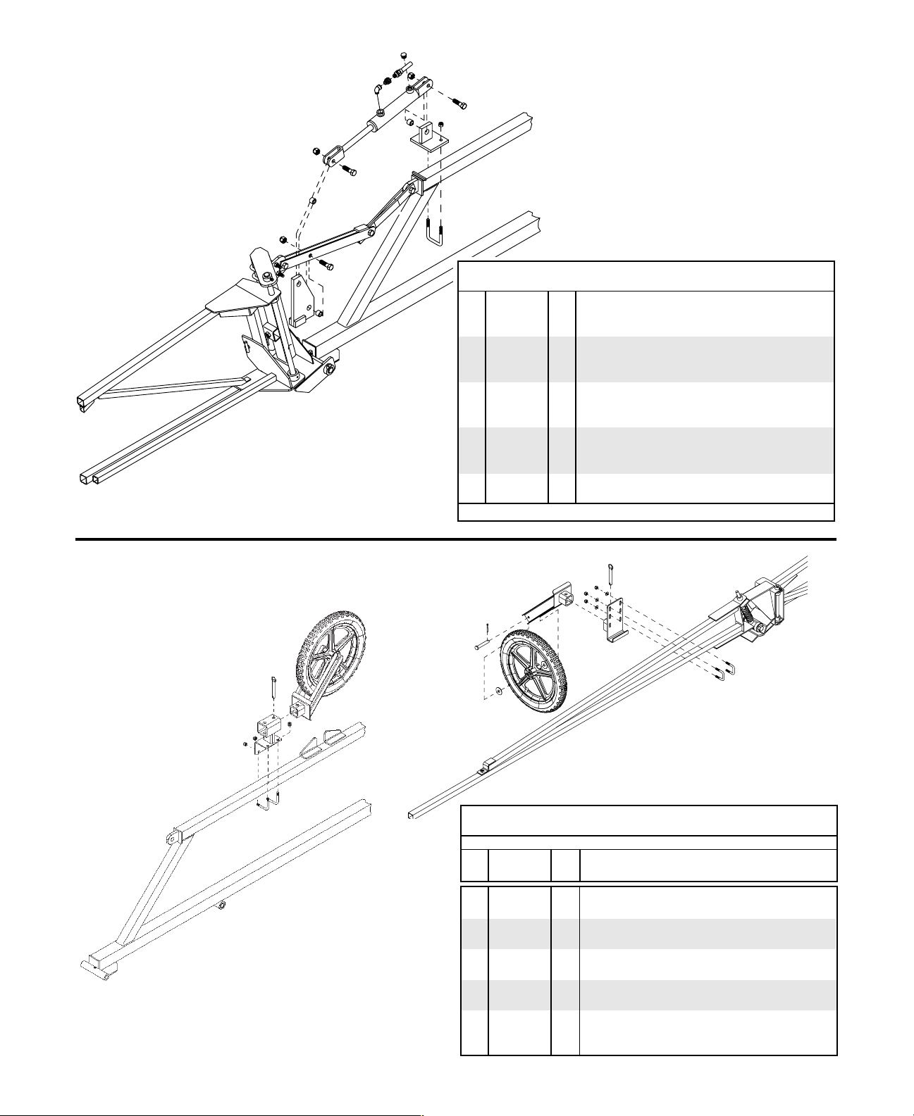
(OPTIONAL) HYDRAULIC BOOM LEVELING PARTS BREAKDOWN
13
9
6
8
12
7
11
6
5
11
1
5
3
6
10
2
5
4
11
REF. PART
NO. NO. QTY DESCRIPTION
1. 03348 1 Left DFHY Cylinder Mount
- 03349 1 Right DFHY Cylinder Mount
2. 02128 2 3/8"-16UNC x 2" Square U-bolt
3. 02592 4 3/8"-16UNC Nylon Insert Locknut
4. 03350 2 Linkage Mount
5. 01253 6 1/2"-13UNC x 2" Hex Head Bolt Gr.5
6. 02178 6 1/2"-13UNC Nylon Insert Locknut
7. 00286 2 Hydraulic Cylinder
8. 05661 2 3/8" MPT x 3/8" FPT Orifice Restrictor
9. 05013 2 26' Hydraulic Hose
10. 03405 2 Lower Linkage Mount
11. 01839 6 Bushing (3/4" OD x 1/2" ID x 5\8"lg.)
12. 05215 2 3/8" Steel Elbow Fitting
13. 00288 2 Air Vent
- 5222 - Cylinder Repair Kit
Please order replacement parts by PART NO. and DESCRIPTION.
DFHY PARTS LIST
(OPTIONAL) WHEEL TIP PROTECTOR PARTS BREAKDOWN
7
6
1
2
7
11
9
9
5
3
2
4
9
13
8
1
10
12
DFBTP PARTS LIST
REF. PART
NO. NO. QTY DESCRIPTION
- 5328 2 16" Nylon Rim Assembly with Tire & Tube
1. 04744 1 16" x 2-1/8" Rubber Tire with Tube
2. 04743 1 16" Glass Filled Nylon Rim with Bearing
3. 05619 2 Pin (1/2" x 3" lg.)
4. 02384 4 Machine Washer (1/2" ID x 14 GA.)
5. 00185 2 5/32" x 1 Cotter Pin
6. 05564 2 Wheel Fork
7. 05328 2 1/2" x 3" lg. Ball Lock Hitch Pin
8. 05566 2 Wing Mounting Plate
9. 02802 12 5/16"-18UNC Nylon Insert Locknut
10. 00909 4 5/16"-18UNC x 1-1/4" Square U-bolt
11. 05567 1 Transport Storage Bracket
12. 05818 2 5/16"-18UNC x 2-1/2 L-bolt
13. 00004 8 5/16" Flatwasher
Please order replacement parts by PART NO. and DESCRIPTION.
Page 12
Page 15

SPRAYER CALIBRATION PROCEDURES
NOTE: To avoid wind drift, use lower pressure and higher spray volume.
Guidelines For Sprayer Calibration
Before calibrating your sprayer, first determine whether each nozzle is delivering at a uniform rate. Place
quart jars under all nozzles and watch as they fill up. The level should rise uniformly and take the same
time (within 10%) for all nozzles to fill the jars. Replace any nozzle showing a discharge rate different from
the others.
Sprayer Tips
Calibrating the Sprayer
1. Mark off 660 feet (1/8 mile).
2. Fill the tank with water.
3. Set the sprayer to your desired operating pressure.
4. Turn the sprayer on and drive at the constant speed you
will be spraying. Calibration on a road or unplowed field
will give different results than on soft cultivated ground.
Note tachometer reading so same speed can be maintained later.
5. Measure the amount of water it takes to refill the tank
completely.
6. Calculate the amount applied:
Number of gallons used x 66 (factor) Gallons applied
Spray Swath in Feet per acre
Example: If 10 gallons are used in 660 feet and the spray
swath is 40 feet, spraying rate is 16.5 gallons per acre.
10 x 66 660
40 40
=
or 16.5 gallons per acre
7. To calculate the amount of chemical to put in the tank:
Sprayer Tank Size Acres
Desired GPA Covered
Recommended amount
of chemical per acre
=
x
Covered
Acres
Example: If a 500 gallon tank is used and 16.5 gallons per
acre are applied, one tank will cover 30.3 acres. If three
pounds of chemical are required per acre, then 90 pounds
of chemical is required per tankful.
=
then;
Amount of
=
chemical per
tankful
Nozzle
XR8001VS X 20 .07 5.3 4.3 2.8 2.2
XR80015VS X 20 .11 7.8 6.3 4.3 3.2
XR8002VS X 20 .14 10.5 8.4 5.6 4.2
XR8003VS X 20 .21 15.7 12.6 8.4 6.3
XR8004VS X 20 .28 21.0 16.8 11.2 8.4
XR8005VS X 20 .35 26.0 21.0 14.0 10.5
XR8006VS X 20 .42 31.0 25.0 16.9 12.6
XR8008VS X 20 .56 42.0 34.0 22.0 17.0
8010SS X 20 .70 53.0 42.0 28.0 21.0
FLAT SPRAY NOZZLE for Broadcast Spraying
Gallons Per Acre
Based on 20" Nozzle Spacing
4 5 7.5 10
MPH MPH MPH MPH
No.
Liquid
Pressure
in PSI
Nozzle
Capacity
in GPM
25 .08 5.9 4.7 3.1 2.4
30 .09 6.4 5.1 3.4 2.6
40 .10 7.4 6.0 4.0 3.0
25 .12 8.8 7.1 4.7 3.6
30 .13 9.7 7.7 5.2 3.9
40 .15 11.1 8.9 6.0 4.5
25 .16 11.8 9.4 6.3 4.7
30 .17 12.9 10.3 6.9 5.2
40 .20 14.8 11.8 7.9 5.9
25 .24 17.6 14.1 9.4 7.1
30 .26 19.0 15.4 10.3 7.7
40 .30 22.0 17.8 11.8 8.9
25 .32 24.0 18.7 12.5 9.4
30 .35 26.0 21.0 13.7 10.3
40 .40 30.0 24.0 15.8 11.9
25 .40 29.0 23.0 15.7 11.7
30 .43 32.0 26.0 17.2 12.9
40 .50 37.0 30.0 19.8 14.9
25 .47 35.0 28.0 18.7 14.1
30 .52 39.0 31.0 21.0 15.5
40 .60 45.0 36.0 24.0 17.8
25 .63 47.0 37.0 25.0 19.0
30 .69 52.0 41.0 27.0 21.0
40 .80 59.0 48.0 32.0 24.0
25 .78 59.0 47.0 31.0 24.0
30 .86 64.0 51.0 34.0 26.0
40 1.00 74.0 59.0 40.0 30.0
500
=
30.3 acres covered then;
16.5
3 lbs. (gal.) x 30.3 = 90 lbs. (gal.) per tankful
To determine GPA at other nominal speed.
Tractor Multiply by
Speed Speed Factor
4 mph 1.25
5 mph 1.00
6 mph .83
7.5 mph .67
10 mph .50
To determine GPA for solutions other than water, determine the weight per gallon or specific gravity and use the
following conversion table.
Weight per
Gallon
7.0 lbs. .84 1.09
8.0 lbs. .96 1.02
8.34 lbs. (water) 1.00 1.00
9.0 lbs. 1.08 .96
10.0 lbs. 1.20 .91
11.0 lbs. 1.32 .87
12.0 lbs. 1.44 .83
Page 13
Specific
Gravity
Multiply
By
Page 16

SPRAYER CHECK LIST
Down time in the field caused by breakdowns is costly and time consuming. Many
breakdowns can be eliminated by periodic equipment maintenance. By spending time running over this checklist before seasonal spraying application time and following proper after season care, you can save time and money later on.
SAFETY FIRST
Keep hands, feet, and loose clothing away from rotating parts.
Wear the protective clothing recommended by your chemical
and fertilizer manufacturer when working with chemicals.
Be sure rear safety stand is lowered before unhooking sprayer
from tractor, if the sprayer is equipped with this stand.
CHECK Before Going To The Field:
1. NOZZLES
Check the tip for excessive wear by checking for
grooves in or near the tip opening.
2. HOSES
Check all hoses for worn or soft spots. Be sure all
hose clamps are tightened. Be sure no hoses are
kinked or pinched. Check for leakage in any of the
lines.
3. BOOM HINGES
Clean the hinges and grease to help the breaking
action of the boom.
4. REPLACEMENT PARTS
Replace all worn or damaged parts.
NOTE: Dethmers Manufacturing Company does not
and will not make any recommendations concerning
the application of various chemicals or solutions.
These recommendations relate to either amount or
procedure of materials applied. If you have any questions regarding the application of certain chemicals
or solutions, contact your chemical supplier and follow chemical manufacturer recommendations.
After Season Care
NOTE: It is important that when cleaning the sprayer
one wears proper safety equipment. See your chemical or fertilizer package for this information.
1. After spraying chemicals, run water mixed with
ammonia through the tank, pump, and all hose
hookups. If wettable powder dries out in the system, it is very difficult to put back into suspension
and can cause malfunction, damage or injury.
2. Disassemble the tips and rinse with water or cleaning solution. (Appropriate for chemical sprayed).
3. Clean the tip opening with a wooden toothpick.
Never use wire or a hard object that could distort
the opening.
4. Water rinse and dry the tips before storing.
5. Be sure to dispose of all unused chemicals or solutions in a proper and ecologically sound manner.
DETHMERS MFG. COMPANY
P.O. BOX 189
4010 320 th St., BOYDEN, IA. 51234
PH: (712) 725-2311 or (712) 725-2302
FAX: (712) 725-2380
TOLL FREE: 1-800-54DEMCO (1-800-543-3626)
 Loading...