

Page 1
90016
ERGO-E.EAZY Sit/Stand
Assembly Instructions
Page 2
WOW
90016 Ergo-E.Eazy Sit/Stand
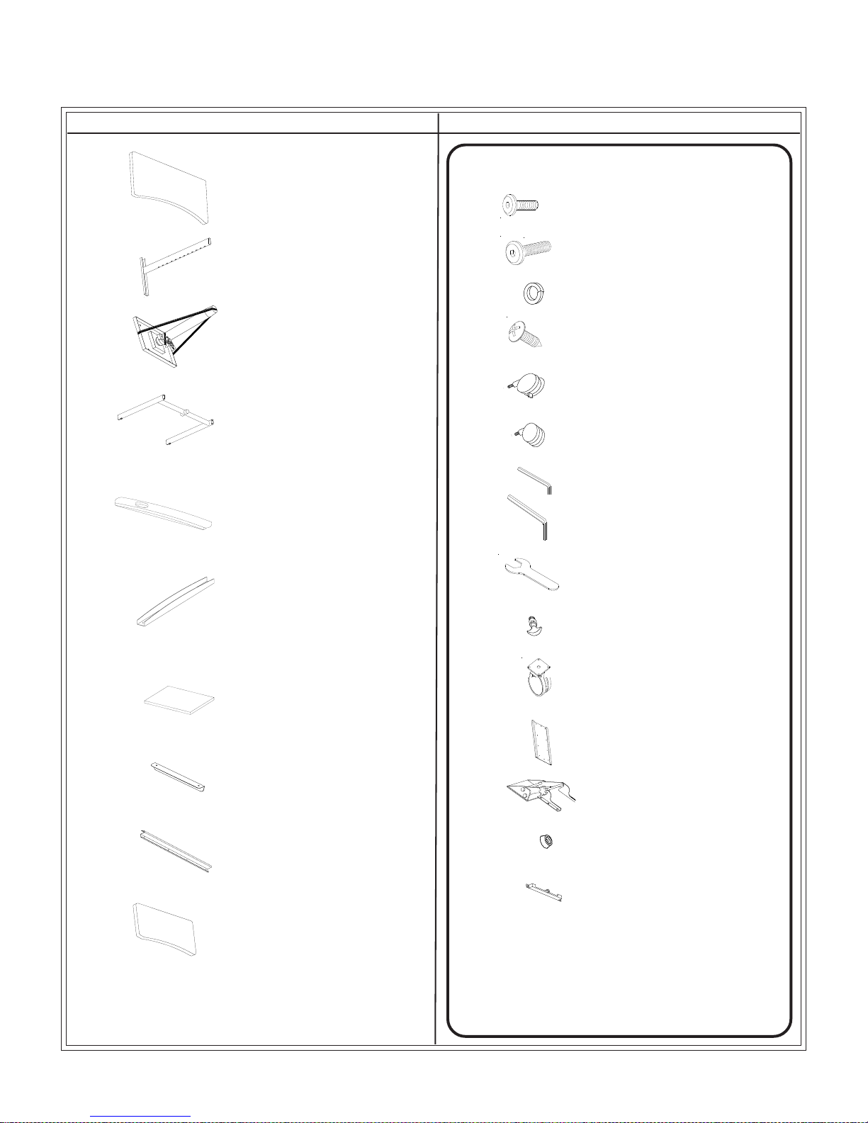
Part Drawing Description Qty
P1 Top Panel 1 EA
P2 Upper Leg 2 EA
P3 Center Post 1 EA
P4 Lower Leg 1 EA
P5 Foot 2 EA
Part Drawing Description Qty
Hardware List
A
A1 Screw M8*25mm 4 EA
B Lock Washer 4 EA
C Wood Screw 22 EA
D Locking Caster 2 EA
E Non-Locking Caster 2 EA
F Allen Wrench (M6) 1 EA
G Allen Wrench (M8) 1 EA
Screw M6*15mm 22 EA
P6 CPU Brace 2 EA
P7 CPU Shelf 1 EA
P8 CPU Side Brace 1 EA
P9 Cable Tray 1 EA
P10 Keyboard Shelf 1 EA
H Caster Wrench 1 EA
I T-Handle 2 EA
J Plate Caster 1 EA
K1 Keyboard Plate 1 EA
K2 Keyboard Adjuster 1 EA
K3 Keyboard Stop 1 EA
K4 Keyboard Cap 1 EA
2
Page 3
R
EAD THROUGH INSTRUCTIONS FROM BEGINNING
TO END
BEFORE
1.)
Identify and Separate all the Parts
STARTING TO ASSEMBLE UNIT
and Hardware.
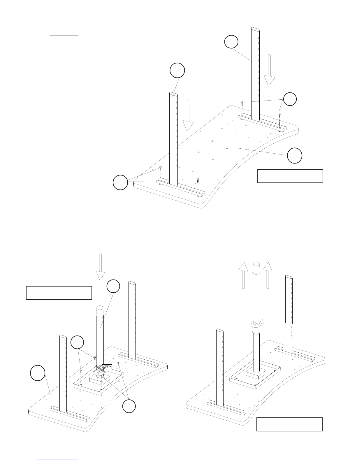
2.)
Place the Top
Panel (P1) upside
down on a padded surface.
Take an Upper Leg (P2) and line
it up with the embedded
threaded inserts on the left side
of the Top. Attache the Upper
Leg using two Screws (A).
Tighten with Allen Wrench (F).
Repeat this Step to attach the
second Upper Leg (P2) on the
right side of the Top as shown in
illustration #1.
A
.
P2
P2
A
P1
Illustration # 1
Cut the large safety strap on the Center Post.
3a.)
Attach the Center Post (P3) to the bottom of
the Top
Panel (P1) using four Screws (A) as
shown in illustration #2a.
Illustration # 2a
A
P1
P3
3b
After
.)
the Center Post is attached to the
Top, carefully cut the Safety Strap that
is around the Adjustment Lever. Stand
to the side and open the Lever to allow
the post to extend.
A
Illustration # 2b
3
Page 4

4.)
Slide
the Lower Leg (P4) down
onto the two Upper Legs (P2)
and the Center Post (P3) as
shown in illustration #3.
P4
P2
Illustration # 3
P2
P3
Attach a Foot (P5) to the bottom of the left
5.)
vertical
post of the Lower Leg (P4) using two
Screws (A1). Tighten Screws using Allen
Wrench (G). Repeat this Step to instal the
second Foot to the right vertical post as
shown in illustration #4.
A1
A1
P5
P5
Illustration # 4
4
Page 5

6.)
Attach
two CPU Braces (P6) to the bottom of either
the Right Foot or the Left Foot using two Screws (A)
to secure each. Attach the CPU Shelf (P7) to the
CPU Braces using four Screws (A) as shown in
illustration #5. Tighten Screws with Allen Wrech (F).
CPU can be
attached
to
this foot
A
P6
P7
7.)
Attach the CPU Side Brace (P8) to
the
outside edge of the CPU Shelf
(P7) using two Screws (A) as shown
in illustration #6.
Illustration # 5
A
P8
Illustration #6
5
Page 6

8.)
Place a Lock Washer
(B) on each
Caster’s thread stem before installing.
Install two Locking Casters (D) on the user
side of the unit. Install two Non-Locking
Casters (E) on the back side of the unit as
shown in illustration #7. Tighten Casters
using Caster Wrench (H).
B
D
E
B
E
B
Illustration #7
D
B
9.)
Attach
the Cable Tray (P9) to the back edge of
the Top Panel (P1) using four Wood Screws (C)
into the predrilled holes. The Cable Tray can
be turned so that the opening will face to the
back or turned so it faces the user.
See illustration #8.
C
P9
C
P1
Illustration #8
6
Page 7

10.)
Screw
in a T-Handle (I) height adjuster
into each leg as shown in illustration #9.
I
Illustration #9
I
11.)
Attach
the Keyboard Plate (K1) to either the right
or left side of the Top. Line up the plate with the
predrilled holes in the Top. Use eight Wood
Screws (C) to secure the plate to the bottom of
the Top Panel.
C
K1
Illustration #10
7
Page 8

12.)
Attach the rubber Keyboard
Stop (K3) to the back of the Keyboard
Plate (K1) using one Wood Screw (C).
C
K3
Illustration #11
13.)
Slide the Keyboard Adjuster
Attach the Keyboard Cap (K4) to the end of the Keyboard Plate as shown in Detail #1.
Secure the Keyboard Cap in place using three Wood Screws (C).
(K2) into the Keyboard Plate (K1) as shown in illustration #12.
K1
K2
K4
Detail
#1
Illustration #12
8
Page 9

14.)
Attach the Keyboard Shelf (P10) to
the
Keyboard Adjuster (K2) using
six Wood Screws (C) as shown in
illustration #13.
P10
C
Illustration #13
15.)
Attach
Plate Caster (J) to the bottom of the CPU Shelf (P7) using four Screws (A)
as shown in illustration #14.
A
J
P7
Illustration #14
9
Page 10

90016
ERGO-E.EAZY Sit/Stand
23 5/8”
47 1/2”
11 3/4” X 26 3/4”
Keyboard Shelf
30 1/2”-
46”
22”
7 7/8”
36 1/4”
Find Balt® Ergo E. Eazy Sit/Stand Workstation @demco.com
Search:
1372187
Call 800.962.4463 or email custserv@demco.com
X 15 3/4”
CPU Shelf
90016_02-25-16
10
 Loading...