


TURBO UMAC

^1 HARDWARE REFERENCE MANUAL
^2 3U Turbo CPU Board
(3U Turbo PMAC2)
^3 HRM for UMAC Turbo & Turbo Stack
^4 3xx-603382-xHxx
^5 June 8, 2004
Single Source Machine Control Power // Flexibility // Ease of Use
21314 Lassen Street Chatsworth, CA 91311 // Tel. (818) 998-2095 Fax. (818) 998-7807 // www.deltatau.com

Copyright Information
© 2003 Delta Tau Data Systems, Inc. All rights reserved.
This document is furnished for the customers of Delta Tau Data Systems, Inc. Other uses are
unauthorized without written permission of Delta Tau Data Systems, Inc. Information contained
in this manual may be updated from time-to-time due to product improvements, etc., and may not
conform in every respect to former issues.
To report errors or inconsistencies, call or email:
Delta Tau Data Systems, Inc. Technical Support
Phone: (818) 717-5656
Fax: (818) 998-7807
Email: support@deltatau.com
Website: http://www.deltatau.com
Operating Conditions
All Delta Tau Data Systems, Inc. motion controller products, accessories, and amplifiers contain
static sensitive components that can be damaged by incorrect handling. When installing or
handling Delta Tau Data Systems, Inc. products, avoid contact with highly insulated materials.
Only qualified personnel should be allowed to handle this equipment.
In the case of industrial applications, we expect our products to be protected from hazardous or
conductive materials and/or environments that could cause harm to the controller by damaging
components or causing electrical shorts. When our products are used in an industrial
environment, install them into an industrial electrical cabinet or industrial PC to protect them
from excessive or corrosive moisture, abnormal ambient temperatures, and conductive materials.
If Delta Tau Data Systems, Inc. products are exposed to hazardous or conductive materials and/or
environments, we cannot guarantee their operation.

3U Turbo CPU Board for UMAC Turbo & Turbo Stack
Table of Contents
INTRODUCTION.......................................................................................................................................................1
UMAC CPU Boards......................................................................................................................................................1
Associated Manuals.......................................................................................................................................................1
3U Board Configurations...............................................................................................................................................1
3U Product Configurations (General Description)........................................................................................................2
UMAC CPU Basic Specifications.................................................................................................................................3
Physical Specifications..............................................................................................................................................3
Electrical Specifications............................................................................................................................................3
BOARD CONFIGURATION.....................................................................................................................................5
Option 2: Bus Interfaces...............................................................................................................................................5
Option 4: CPU Type.....................................................................................................................................................5
Option 5: CPU and Memory Configurations................................................................................................................5
Option 8: High-Accuracy Clock Crystal ......................................................................................................................6
Option 9: Serial Port Configuration..............................................................................................................................6
Option 10: Firmware Revision Specification ...............................................................................................................6
Option 16: Battery-Backed Parameter Memory...........................................................................................................6
Option 18: Identification Number and Real Time Clock/Calendar Module.................................................................7
HARDWARE SETUP.................................................................................................................................................9
Clock Source Jumpers...................................................................................................................................................9
Watchdog Timer Jumper...............................................................................................................................................9
Operation Mode Jumpers...............................................................................................................................................9
Firmware Reload Jumper...............................................................................................................................................9
Re-Initialization Jumper................................................................................................................................................9
Reference Voltage Connect Jumper ............................................................................................................................10
Interrupt Select Jumpers..............................................................................................................................................10
Serial-Port Level Select Jumpers.................................................................................................................................10
Re-Initialization Jumper..............................................................................................................................................10
CONNECTIONS.......................................................................................................................................................11
Stack Connections.......................................................................................................................................................11
Backplane (UMAC) Connections................................................................................................................................11
PC/104 Connections....................................................................................................................................................11
Serial Port Connections...............................................................................................................................................11
Power Supply Connections..........................................................................................................................................11
BOARD JUMPERS AND PINOUTS.......................................................................................................................13
E0: Factory Use Only.................................................................................................................................................13
E1A: Servo and Phase Clock Direction Control.........................................................................................................14
E1B: Servo/Phase Clock Source Control....................................................................................................................14
E2: Reserved for Future Use.......................................................................................................................................14
E3: Re-Initialization on Reset Control........................................................................................................................14
E4: Reserved for Future Use.......................................................................................................................................14
E7 – E10: IRQ PC Interrupt Select.............................................................................................................................15
E12: Digital/Analog Reference Connect....................................................................................................................15
E17 – E18: Serial Port Select......................................................................................................................................15
E19: Watchdog Disable Jumper.................................................................................................................................15
E20 – E22: Power-Up/Reset Load Source..................................................................................................................16
E23: Firmware Reload Enable....................................................................................................................................16
DIP Switch Block S1: PC Bus Base Address.............................................................................................................16
BOARD CONNECTOR SUMMARY......................................................................................................................17
BOARD CONNECTOR PINOUTS.........................................................................................................................19
J7: RS-232/422 Serial Port Connector........................................................................................................................19
Table of Contents i

3U Turbo CPU Board for UMAC Turbo and Turbo Stack
J8: Auxiliary Serial Port Connector (RS232) .............................................................................................................20
TB1: 4-Pin Terminal Block.........................................................................................................................................20
ACCESSORIES.........................................................................................................................................................21
ii Table of Contents

3U Turbo CPU Board for UMAC Turbo and Turbo Stack
INTRODUCTION
Delta Tau’s 3U-format Turbo PMAC systems combine the power of the Turbo PMAC family with an
integrated packaging strategy that gives the user revolutionary flexibility and ease of use. The heart of
these systems is the 3U Turbo PMAC CPU board, described in this manual. It can either be assembled
with piggyback accessory boards to form a “Turbo Stack,” or connected through a backplane to rackmounted accessories to form a UMAC (Universal Motion and Automation Controller) Turbo system.
UMAC systems provide integrated connectivity as well as ease of assembly, diagnostics, and repair.
UMAC CPU Boards
The UMAC is available with either of two CPU boards – Turbo PMAC2 or MACRO Station.
The Turbo PMAC2 CPU board creates a UMAC Turbo, a full PMAC controller completely capable of
standalone operation.
The MACRO Station CPU board creates a UMAC MACRO. It is a remote slave node on a MACRO
ring, requiring a PMAC2 controller to command it over the ring.
This manual describes the hardware for the UMAC Turbo CPU board; for the UMAC MACRO CPU
board, consult the hardware reference manual for that product.
Associated Manuals
This document is the Hardware Reference Manual for the 3U Turbo CPU board for a UMAC Turbo
system. It describes the hardware features and provides setup instructions.
Other manuals as well are needed to use the UMAC Turbo system. Each accessory to the 3U Turbo CPU
board has its own manual, describing its operation and any required software setup of the Turbo CPU.
The Software Reference Manual for the Turbo PMAC family and the User’s Guide for the PMAC or
Turbo PMAC families is also needed.
3U Board Configurations
The 3U boards can be configured in either of two fundamental assemblies – UMAC and Stack.
• UMAC – In the UMAC configuration (once called Pack) the 3U-format
boards are put together to communicate through a backplane bus called
the UBUS, with all boards installed in a Euro-card rack. In this
configuration, all 3U-format boards or modules can be installed or
withdrawn from the pack individually, providing ease of installation,
debugging, and repair.
The photo at right shows two boards connected through a backplane in the
UMAC configuration. They are not connected directly to each other.
• Stack – In the Stack configuration the 3U-format boards are put together
as a stack of piggyback boards, (right, below). This configuration is ideal
for compact, cost-sensitive embedded applications.
Note:
The Stack boards and related breakout boards can be installed in a
Euro-card rack, creating a hybrid stack/pack configuration.
Because the Stack boards were developed first, this originally was
the only way of creating a pack configuration, and pulling boards
for service was an awkward chore. This configuration should now
be used for existing legacy systems only.
Two boards in UMAC
Configuration
Two Boards in Stack
Configuration
Introduction 1
3U Turbo CPU Board for UMAC Turbo and Turbo Stack
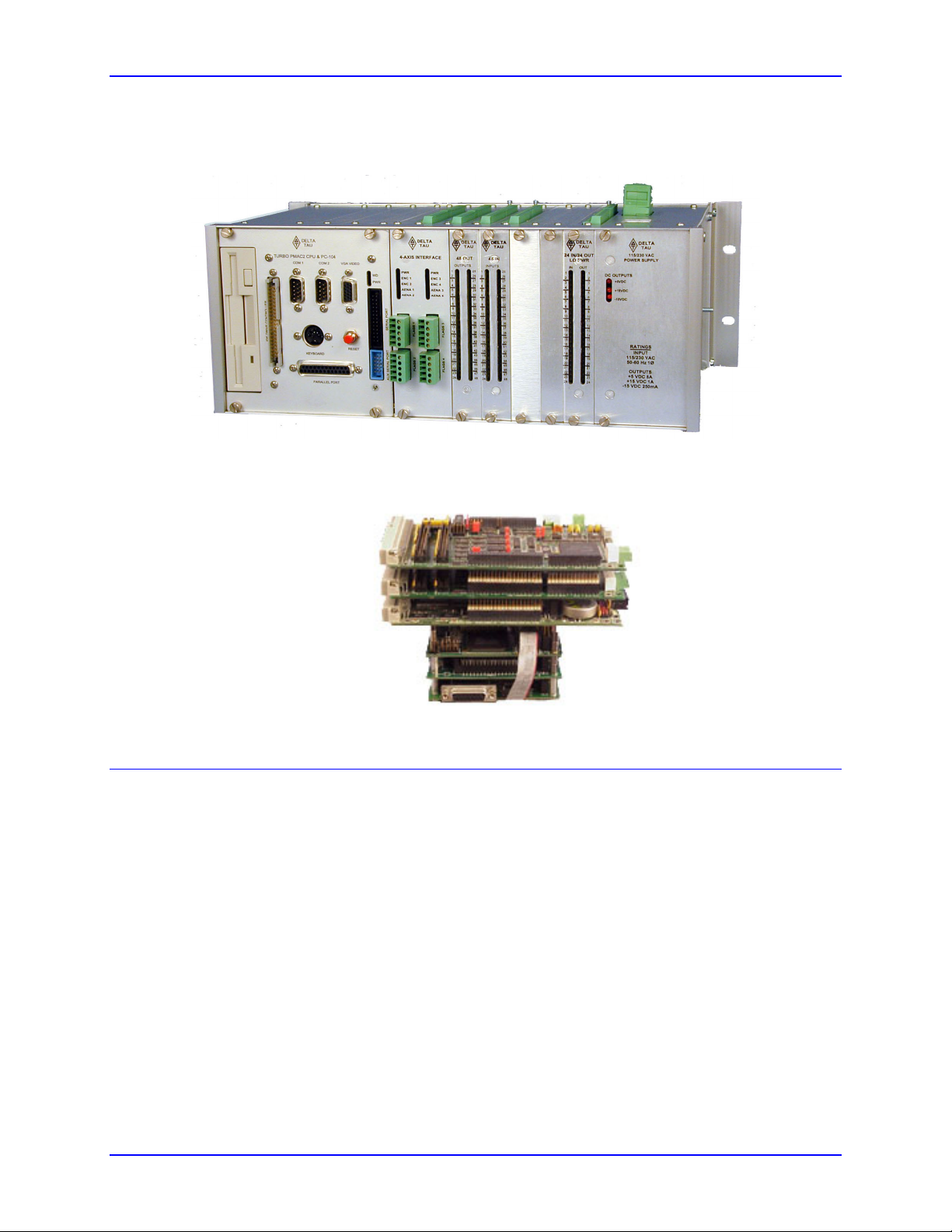
The following two photos show typical UMAC and Stack configurations. They are intended only to show
what a completed system may look like, not to be instructions on how to put a particular system together.
Sample UMAC Configuration:
Turbo PMAC2 CPU and PC/104, Acc-24E2 4-Axis Interface, Acc-10E 48 Out, Acc-9E 48 In,
Acc-11E 24 In/24 Out Low Power, Accessory E Power Supply
Sample Stack Configuration:
PC/104 Computer, Turbo PMAC2 CPU, Two Acc-2E 4-Axis Interface Boards
3U Product Configurations (General Description)
Assemblies of 3U-format boards can be made with either of two CPU processor boards – a 3U MACROCPU board, or a 3U Turbo PMAC2 CPU board. Most other 3U-format boards, labeled Accessory boards,
can be used with either CPU board.
• When the 3U MACRO-CPU board is used, the resulting assemblies are called UMAC MACRO or
3U MACRO Stack.
• When the 3U Turbo PMAC2 CPU board is used, the resulting assemblies are called UMAC Turbo or
Turbo Stack.
Refer to the UMAC and 3U Stack Products Selection Guide for more detailed descriptions of how the
rack and stack products are integrated.
2 Introduction

3U Turbo CPU Board for UMAC Turbo and Turbo Stack
UMAC and 3U-Stack Products
UMAC Products Stack Products
UMAC Turbo UMAC MACRO Turbo Stack MACRO Stack
The UMAC Turbo is composed of
a 3U-format Turbo PMAC2 CPU
board and a set of accessory boards
in 3U-format, all plugged in a
common UBUS backplane and
installed inside a 3U format rack. A
PC/104 computer and several
optional communication
accessories (including all of the
major FieldBuses, MACRO and
Ethernet) can be installed inside the
UMAC system providing
convenient flexi bil ity and virtually
unlimited expandability.
The UMAC MACRO is composed
of a MACRO Interface/C PU board
and a set of accessory boards in 3Uformat, all plugged in a common
UBUS backplane and installed
inside a 3U format rack. The UMAC
MACRO must receive com mands
from an external MACRO
compatible devi ce like a PMAC2
Ultralite or a UMAC Turbo system.
The UMAC MACRO does not
support a PC/104 or communication
accesso ries an d it is pref erred for
distribu ted co ntr ol ove r a MACRO
ring connection .
The Turbo stack is compos ed of a
3U-format Turbo PMAC2 CPU
board and a set of accessory boards
in 3U-format plugged to it in a stack
configuration. The Turbo stack
configu r atio n is les s ex pe ns iv e than
the UMAC Turbo system but it is
limited to eight axes of motion
contro l versus 32 axes on a UMAC
Turbo system. The Turbo Stack is
selected over a UMAC Turbo
system because is more compact,
allowing its installation inside
already ex is ti n g ca bi n e ts with s o me
space limi ta ti ons .
The MACRO stack is composed of
a MACRO Interface/CPU board
and a set of access ory boards in
3U-format plugged t o i t in a stac k
configuration. The UMAC
MACRO must receive commands
from an external MACRO
compatible device li ke a PMAC2
Ultralite or a UMAC Turbo
system. The MACRO Stack is
selected over a UMAC MACRO
system because it is more compact,
allowing its installation inside
already existing cabinets with some
space limi ta ti ons .
UMAC CPU Basic Specifications
Physical Specifications
Size: 16cm x 9.9cm x 3.8cm (6.3" x 3.9" x 1.4")
Weight: ¼ lb.
Temperature
Operating: 0°C to 60°C (32°)F to 140°F)
Storage: 12°C to 82°C (10°F to 180°F)
Humidity: 10% to 95%, non-condensing
Electrical Specifications
Power: 1A @ +5V (±5%)
Battery: 3.0V Lithium Cell, 1200mAh, 2/3A-size, no tabs; or 3.6V Lithium Cell, 1000 mAh,
1.00" can
Expected battery life: 10 years (standard), 6-9 months (Opt. 5).
Recommended replacement: 24 months (standard), 3-6 months (Opt. 5)
Introduction 3

3U Turbo CPU Board for UMAC Turbo and Turbo Stack
4 Introduction
 Loading...