


^1
^2
HARDWARE REFERENCE MANUAL
Turbo PMAC Clipper
^3Turbo PMAC Clipper
^4 4xx-603871-xAxx
^5April 15, 2014
DELTA TAU
Data Systems, Inc.
NEW IDEAS IN MOTION …
Single Source Machine Control ……………………………………………..…...………………. Power // Flexibility // Ease of Use 21314 Lassen St. Chatsworth, CA 91311 // Tel. (818) 998-2095 Fax. (818) 998-7807 // www.deltatau.com

Turbo PMAC Clipper
Copyright Information
© 2014 Delta Tau Data Systems, Inc. All rights reserved.
This document is furnished for the customers of Delta Tau Data Systems, Inc. Other uses are unauthorized without written permission of Delta Tau Data Systems, Inc. Information contained in this manual may be updated from time-to-time due to product improvements, etc., and may not conform in every respect to former issues.
To report errors or inconsistencies, call or email:
Delta Tau Data Systems, Inc. Technical Support
Phone: (818) 717-5656 Fax: (818) 998-7807
Email: support@deltatau.com Website: http://www.deltatau.com
Operating Conditions
All Delta Tau Data Systems, Inc. motion controller products, accessories, and amplifiers contain static sensitive components that can be damaged by incorrect handling. When installing or handling Delta Tau Data Systems, Inc. products, avoid contact with highly insulated materials. Only qualified personnel should be allowed to handle this equipment.
In the case of industrial applications, we expect our products to be protected from hazardous or conductive materials and/or environments that could cause harm to the controller by damaging components or causing electrical shorts. When our products are used in an industrial environment, install them into an industrial electrical cabinet or industrial PC to protect them from excessive or corrosive moisture, abnormal ambient temperatures, and conductive materials. If Delta Tau Data Systems, Inc. products are directly exposed to hazardous or conductive materials and/or environments, we cannot guarantee their operation.

Turbo PMAC Clipper
Safety Instructions
Qualified personnel must transport, assemble, install, and maintain this equipment. Properly qualified personnel are persons who are familiar with the transport, assembly, installation, and operation of equipment. The qualified personnel must know and observe the following standards and regulations:
IEC364resp.CENELEC HD 384 or DIN VDE 0100 IEC report 664 or DIN VDE 0110
National regulations for safety and accident prevention or VBG 4
Incorrect handling of products can result in injury and damage to persons and machinery. Strictly adhere to the installation instructions. Electrical safety is provided through a low-resistance earth connection. It is vital to ensure that all system components are connected to earth ground.
This product contains components that are sensitive to static electricity and can be damaged by incorrect handling. Avoid contact with high insulating materials (artificial fabrics, plastic film, etc.). Place the product on a conductive surface. Discharge any possible static electricity build-up by touching an unpainted, metal, grounded surface before touching the equipment.
Keep all covers and cabinet doors shut during operation. Be aware that during operation, the product has electrically charged components and hot surfaces. Control and power cables can carry a high voltage, even when the motor is not rotating. Never disconnect or connect the product while the power source is energized to avoid electric arcing.
A Warning identifies hazards that could result in personal injury or death. It precedes the discussion of interest.
Warning
A Caution identifies hazards that could result in equipment damage. It precedes the discussion of interest.
Caution
A Note identifies information critical to the understanding or use of the equipment. It follows the discussion of interest.
Note

Turbo PMAC Clipper
REVISION HISTORY
REV. |
|
DESCRIPTION |
DATE |
CHG |
|
APPVD |
|
|
|
|
|
|
|
9 |
Changed name of manual to Turbo PMAC Clipper |
11/03/09 |
CP |
|
DD |
|
|
|
|
|
|
|
|
10 |
Adjusted diagram on P.31 |
12/16/09 |
CP |
|
SM |
|
|
|
|
|
|
|
|
11 |
Added pulse and direction setup, updated fifth motor setup |
06/10/10 |
RN |
|
SM |
|
|
|
|
|
|
|
|
12 |
Updated power supply information |
03/17/12 |
GS |
|
SM |
|
|
|
|
|
|
|
|
13 |
General formatting and corrections |
04/15/14 |
MC |
|
RN |
|
|
|
|
|
|
|
|
|
|
|
|
|
|
|
Older revision correction notes have been removed for clarity.
Note


Turbo PMAC Clipper
Table of Contents |
|
INTRODUCTION................................................................................................................................. |
9 |
Documentation ........................................................................................................................................ |
9 |
Downloadable Turbo PMAC Script ....................................................................................................... |
10 |
SPECIFICATIONS ............................................................................................................................. |
11 |
Part Number .......................................................................................................................................... |
11 |
Options ................................................................................................................................................. |
12 |
Environmental Specifications ................................................................................................................ |
13 |
Electrical Specifications ........................................................................................................................ |
13 |
Digital Power Supply ....................................................................................................................... |
13 |
DAC Outputs Power Supply.............................................................................................................. |
13 |
Flags Power Supply.......................................................................................................................... |
13 |
RECEIVING AND UNPACKING...................................................................................................... |
14 |
Use of Equipment .................................................................................................................................. |
14 |
MOUNTING........................................................................................................................................ |
15 |
Physical Specifications .......................................................................................................................... |
16 |
Board Dimensions and Layout.......................................................................................................... |
16 |
CONNECTIONS AND SOFTWARE SETUP.................................................................................... |
17 |
TB1: Power Supply Input ...................................................................................................................... |
17 |
J2: Serial Port ........................................................................................................................................ |
18 |
J3: Machine Connector (JMACH1 Port) ................................................................................................ |
19 |
Setting up Quadrature Encoders....................................................................................................... |
22 |
Setting up Sinusoidal Encoders......................................................................................................... |
22 |
Counts per User Units ...................................................................................................................... |
24 |
Wiring the DAC Output .................................................................................................................... |
25 |
Amplifier Enable Signal (AENAn/DIRn) ........................................................................................... |
26 |
Amplifier Fault Signal (FAULT-)...................................................................................................... |
27 |
Optional Analog Inputs .................................................................................................................... |
28 |
Analog Inputs Setup.......................................................................................................................... |
28 |
J4: Machine Connector (JMACH2 Port) ................................................................................................ |
29 |
Overtravel Limits and Home Switches .............................................................................................. |
30 |
Wiring the Limits and Flags ............................................................................................................. |
30 |
Limits and Flags [Axis 1- 4] Suggested M-Variables ........................................................................ |
33 |
Step and Direction PFM Output (To External Stepper Amplifier)...................................................... |
34 |
Compare Equal Outputs ................................................................................................................... |
35 |
J7: Machine Connector (JMACH3 Port) ................................................................................................ |
36 |
J8: Thumbwheel Multiplexer Port (JTHW Port)..................................................................................... |
37 |
Thumbwheel Port Digital Inputs and Outputs ................................................................................... |
38 |
J9: General-Purpose Digital Inputs and Outputs (JOPT Port) ................................................................. |
39 |
General Purpose I/Os (J6) Suggested M-Variables ........................................................................... |
41 |
J10: Handwheel and Pulse/Dir Connector (JHW/PD Port)...................................................................... |
42 |
Table of Contents |
vi |

Turbo PMAC Clipper
J12: Ethernet Communications Port ....................................................................................................... |
43 |
J13: USB Communications Port ............................................................................................................ |
43 |
JP11: OPT-11 Shunt .............................................................................................................................. |
43 |
LED Indicators ...................................................................................................................................... |
43 |
DRIVE - MOTOR SETUP.................................................................................................................. |
44 |
Filtered PWM Output (Analog ±10V).................................................................................................... |
45 |
Clock Settings, Output Mode, Command Limit.................................................................................. |
46 |
Flag Control, Ixx24 .......................................................................................................................... |
47 |
I2T Protection: Ixx57, Ixx58 ............................................................................................................. |
47 |
Open Loop Test: Encoder/Decode .................................................................................................... |
47 |
Position-Loop PID Gains: Ixx30…Ixx39........................................................................................... |
49 |
True DAC Output (±10V)...................................................................................................................... |
50 |
Clock Settings, Output Mode ............................................................................................................ |
50 |
Flag Control, Ixx24 .......................................................................................................................... |
50 |
I2T Protection: Ixx57, Ixx58 ............................................................................................................. |
50 |
Open Loop Test: Encoder/Decode .................................................................................................... |
51 |
Position-Loop PID Gains: Ixx30…Ixx39........................................................................................... |
52 |
Pulse and Direction Output (PFM)......................................................................................................... |
54 |
PFM Clock Settings Example ........................................................................................................... |
54 |
PFM Setup Example ......................................................................................................................... |
55 |
Writing directly to the PFM register ................................................................................................. |
55 |
Issuing Open-Loop Commands ......................................................................................................... |
56 |
Issuing Closed-Loop Commands....................................................................................................... |
56 |
Setup of a Fifth Motor Using Opt-12 on the Clipper Board .................................................................... |
59 |
LASER CONTROL OUTPUT............................................................................................................ |
61 |
Understanding Option-11A Capabilities ................................................................................................ |
62 |
Clock Settings ....................................................................................................................................... |
63 |
Controlling the output............................................................................................................................ |
64 |
TROUBLESHOOTING ...................................................................................................................... |
66 |
Serial Number and Board Revisions Identification ................................................................................. |
66 |
Write-Protect Disable – E8 Jumper ........................................................................................................ |
67 |
Changing IP Address, Gateway IP, Gateway Mask ........................................................................... |
68 |
Enabling ModBus............................................................................................................................. |
69 |
Reloading Boot and Communication Firmware ................................................................................ |
70 |
Reloading PMAC firmware – E13 Jumper ........................................................................................ |
71 |
Re-initialization jumper (Factory Reset) ........................................................................................... |
73 |
Watchdog Timer.................................................................................................................................... |
73 |
APPENDIX A: E-POINT JUMPERS ................................................................................................. |
74 |
E0: Forced Reset Control...................................................................................................................... |
74 |
E1 – E2: Serial Port Selection (rev 102 and below only) ....................................................................... |
74 |
E3: Normal/Re-Initializing Power-Up/Reset ......................................................................................... |
74 |
E4: Watchdog Disable Jumper .............................................................................................................. |
74 |
Table of Contents |
vii |

Turbo PMAC Clipper
E5: Reserved for factory use only ......................................................................................................... |
74 |
E6: ADC Inputs Enable ........................................................................................................................ |
75 |
E7 – E8: USB/Ethernet Reset Jumpers.................................................................................................. |
75 |
E10 – E12: Flash IC Jumpers................................................................................................................ |
75 |
E13: Power-Up/Reset Load Source....................................................................................................... |
76 |
E14E17: Ports Direction Control ......................................................................................................... |
76 |
APPENDIX B: SCHEMATICS .......................................................................................................... |
77 |
Table of Contents |
viii |

Turbo PMAC Clipper
INTRODUCTION
The Turbo PMAC Clipper is a multi-axis stand-alone controller. It has the full power of Turbo PMAC2 CPU and provides a minimum of 4 axes of servo or stepper control. It comes with 32 general-purpose digital I/O points, handwheel port, USB, Ethernet and RS-232 communications links.
The optional axis expansion board provides a set of four additional servo channels and extra I/O ports.
The Turbo PMAC Clipper can be interfaced with several different type of encoders and it supports three types of outputs:
Analog ±10V 12-bit Filtered PWM
Analog ±10V 18-bit True DAC (Optional)
Pulse Frequency Modulation (PFM)
Documentation
In conjunction with this user manual, the Turbo Software Reference Manual and Turbo PMAC User Manual are essential for proper use, motor setup, and configuration of the Turbo PMAC Clipper. It is highly recommended to refer to the latest revision of the manuals found on Delta Tau’s website, under
Support>documentation>Manuals: Delta Tau Manuals
Introduction |
9 |

Turbo PMAC Clipper
Downloadable Turbo PMAC Script
Some code examples require the user to input specific information pertaining to their system hardware. When user information is
required, a commentary ending with –User Input is inserted.
Caution
This manual contains downloadable code samples in Turbo PMAC script. These examples can be copied and pasted into the editor area in the Pewin32pro2. Care must be taken when using pre-configured Turbo PMAC code, some information may need to be updated to match hardware and system specific configurations. Downloadable Turbo PMAC Scripts are enclosed in the following format:
// TURBO PMAC SCRIPT EXAMPLE |
|
|
|
P1=0 |
; Set P1=0 at download |
||
Open PLC 1 Clear |
; Open PLC Buffer 1, clear contents |
||
CMDP"Turbo PMAC Clipper Manual Test PLC" |
; Send unsolicited response to host port |
||
P1=P1+1 |
; Counter using variable P1 |
||
Disable PLC 1 |
; Disable plc 1 |
||
Close |
; Close open buffer |
||
|
|
|
|
|
|
|
|
All PLC examples are stated in PLC number 1. It is the user’s responsibility to arrange their application PLCs’ properly and handle
power-on sequencing for various tasks.
Caution
It is the user’s responsibility to use the PLC examples presented in this manual properly. That is, incorporating the statement code in the application configuration, and handling tasks in a sequential manner. For example, with serial absolute encoders, setting up the global control registers should be executed before trying to read absolute position, and absolute phase referencing. Furthermore, other PLC programs (which would be trying to move motors) should be disabled until these functions are executed.
Often times, downloadable example codes use suggested M-variables, it is the user’s responsibility to make sure they are downloaded, or
perform necessary changes to use the intended registers.
Caution
Introduction |
10 |
Turbo PMAC Clipper
SPECIFICATIONS
Part Number
Connections and Software Setup |
11 |

Turbo PMAC Clipper
Options
CPU Options |
|
C0: |
80MHz Turbo PMAC2 CPU (standard) |
|
8Kx24 internal memory, 256Kx24 SRAM , 1MB flash memory |
C3: |
80MHz Turbo PMAC2 CPU |
|
8Kx24 internal memory, 1Mx24 SRAM, 4M flash memory |
F3: |
240MHz Turbo PMAC2 CPU |
|
192Kx24 internal memory, 1Mx24 SRAM, 4M flash memory |
Communication Options
Opt.2 |
Dual Port RAM (required for NC software/applications) |
|
Opt.15F |
Modbus Communication for additional I/O’s. |
|
|
Opt.EX |
JEXPA & JEXPB stack long pins |
|
Opt.C4 |
JEXPA & JEXPB stack and connectors long pins for breakout board option |
Axis Output
18-bit true DAC or 12-bit filtered PWM (default) ±10V analog output
Pulse And Direction (PFM)
Encoder Input
Four encoder inputs, and two handwheel quadrature input (default)
Additional four encoder inputs (Acc-1P) and two handwheel encoder (Acc-1P Option1)
Digital Inputs/Outputs
32 general-purpose TTL-level I/O points (default)
Additional 8 general-purpose I/O and multiplexed I/O (Acc-1P Option1)
Analog Inputs
Two 12-bit analog inputs, and a 12-bit filtered PWM (±10V) outputs (Opt.12)
Additional two 12-bit analog inputs, and a 12-bit filtered PWM (±10V) outputs (Acc-1P Option2)
Host Communication
USB 2.0, Ethernet 100 Base T, RS232 (default)
Stackable Accessories
ACC-1P PC/104-format Channel 5-8 board
ACC-8AS 4-channel dual 16-bit true-DAC output board
ACC-8ES 4-channel dual 18-bit true-DAC output board
ACC-8FS 4-channel direct-PWM output board
ACC-8TS 4-channel ADC-interface board
ACC-51S 2/4-channel high-resolution encoder interpolator board
ACC-84S 4-channel serial encoder interface. The supported protocols:
|
SSI |
Synchronous Serial Interface |
|
EnDat 2.2 |
EnDat 2.2 interface from HEIDENHAIN |
|
BiSS B |
Renishaw Biss B Unidirectional |
|
BiSS C |
Renishaw Biss C Unidirectional |
|
Yaskawa |
Yaskawa Sigma II and Sigma III feedback support |
|
Panasonic |
Panasonic Feedback Style |
|
Tamagawa |
Tamagawa Feedback Style |
|
Mitutoyo |
Mitutoyo Feedback Style |
Connections and Software Setup |
12 |

Turbo PMAC Clipper
Environmental Specifications
Description |
Specification |
Notes |
|
|
|
Operating Temperature |
0°C to 45°C |
|
|
|
|
Storage Temperature |
-25°C to 70°C |
|
|
|
|
Humidity |
10% to 95 % |
Non-Condensing |
|
|
|
Electrical Specifications
Digital Power Supply
The +5V and ground reference lines from the power supply should be connected to TB1 terminal block of the Turbo PMAC Clipper board using 18 AWG stranded wire. The power requirement (± 5%) is:
+5 V (20W) @ 4 A (Eight-channel configuration with a typical load of encoders)
Boards with revisions 103 and below have the following requirement:
Mininumum 10 msec rise time 6A @ +5V (±5%) (30 W)
The Clipper Board and other stackable accessories each require a WARNING 1A @ 5VDC power supply for normal operation; however, the
Clipper board has an in-rush current requirement that can reach 3A, so a 6A @ 5VDC power supply is recommended.
DAC Outputs Power Supply
The ±12V lines from the supply, including the ground reference, can be brought in either from the TB1 terminal block or from the JMACH1 connector.
+12 to +15 V (4.5W) @ 0.30 A (Eight-channel configuration with a typical load of encoders) -12 to -15 V (3.8W) @ 0.25 A (Eight-channel configuration with a typical load of encoders)
Flags Power Supply
Each channel of PMAC has five dedicated digital inputs on the machine connector: PLIMn, MLIMn (overtravel limits), HOMEn (home flag), FAULTn (amplifier fault), and USERn. A power supply from 5 to 24V must be used to power the circuits related to these inputs. This power supply can be the same used to Turbo PMAC Clipper and can be connected from the TB1 terminal block or the J3 (JMACH1) connector.
Connections and Software Setup |
13 |

Turbo PMAC Clipper
RECEIVING AND UNPACKING
Delta Tau products are thoroughly tested at the factory and carefully packaged for shipment. When the Turbo PMAC Clipper is received, there are several things to be done immediately:
Observe the condition of the shipping container and report any damage immediately to the commercial carrier that delivered the board.
Remove the Turbo PMAC Clipper from the shipping container and remove all packing materials. Check all shipping material for connector kits, documentation, or other small pieces of equipment. Be aware that some connector kits and other equipment pieces may be quite small and can be accidentally discarded if care is not used when unpacking the equipment. The container and packing materials may be retained for future shipment.
Verify that the part number of the board received is the same as the part number listed on the purchase order.
Inspect for external physical damage that may have been sustained during shipment and report any damage immediately to the commercial carrier that delivered the board.
Electronic components in this product are design-hardened to reduce static sensitivity. However, use proper procedures when handling the equipment.
If the Turbo PMAC Clipper is to be stored for several weeks before use, be sure that it is stored in a location that conforms to published storage humidity and temperature specifications.
Use of Equipment
The following restrictions will ensure the proper use of the Turbo PMAC Clipper:
The components built into electrical equipment or machines can be used only as integral components of such equipment.
The Turbo PMAC Clipper must not be operated on power supply networks without a ground or with an asymmetrical ground.
If the Turbo PMAC Clipper is used in residential areas, or in business or commercial premises, implement additional filtering measures.
The Turbo PMAC Clipper may be operated only in a closed switchgear cabinet, taking into account the ambient conditions defined in the environmental specifications.
Delta Tau guarantees the conformance of the Turbo PMAC Clippers with the standards for industrial areas stated in this manual, only if Delta Tau components (cables, controllers, etc.) are used.
Connections and Software Setup |
14 |

Turbo PMAC Clipper
MOUNTING
The location of the Turbo PMAC Clipper is important. Installation should be in an area that is protected from direct sunlight, corrosives, harmful gases or liquids, dust, metallic particles, and other contaminants. Exposure to these can reduce the operating life and degrade performance of the board.
Several other factors should be carefully evaluated when selecting a location for installation:
For effective cooling and maintenance, the Turbo PMAC Clipper should be mounted on a smooth, nonflammable vertical or horizontal surface.
At least 100 mm (0.4 inches) top and bottom clearance must be provided for air flow.
Temperature, humidity and Vibration specifications should also be taken in account.
Unit must be installed in an enclosure that meets the environmental IP rating of the end product (ventilation or cooling may be necessary to
prevent enclosure ambient from exceeding 45° C [113° F]).
Caution
The Turbo PMAC Clipper can be mounted as a stand-alone controller using standoffs. At each of the four corners of the board and at the center edges, there are mounting holes that can be used for this.
The order of the Acc-1P or other stacked accessories with respect to the Clipper Board does not matter. If the Turbo PMAC Clipper is mounted to a back panel, the back panel should be unpainted and electrically conductive to allow for reduced electrical noise interference. The back panel should be machined to accept the standoffs pattern of the board.
The board can be mounted to the back panel using four standoffs and internal-tooth lock washers. It is important that the teeth break through any anodization on the board’s mounting gears to provide a good electrically conductive path in as many places as possible. Mount the board on the back panel so there is airflow at both the top and bottom areas of the board (at least 0.4 inches).
Connections and Software Setup |
15 |

Turbo PMAC Clipper
Physical Specifications
Board Dimensions and Layout
Top View
Rev106
Connections and Software Setup |
16 |
Turbo PMAC Clipper Hardware Reference Manual
CONNECTIONS AND SOFTWARE SETUP
|
Installation of electrical equipment is subject to many regulations |
|
|
including national, state, local, and industry guidelines and rules. |
|
|
The following are general recommendations but it is important |
|
WARNING |
that the integration be carried out in accordance with all |
|
regulations pertaining to the installation. |
||
|
||
|
|
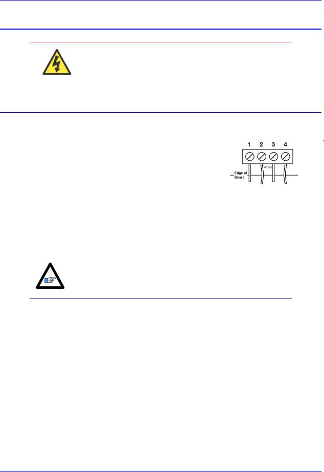
TB1: Power Supply Input
This 4-pin terminal block is used to bring the 5VDC logic power and +/-12VDC DAC supply into the Turbo PMAC Clipper.
|
|
TB1 (JPWR): Power Supply |
|
|
||||
|
|
|
4-Pin Terminal Block |
|
|
|
||
|
|
|
|
|
|
|
|
|
Pin# |
Symbol |
|
Function |
|
Description |
Notes |
||
|
|
|
|
|
|
|
|
|
1 |
|
GND |
|
Common |
|
Digital Common |
|
|
|
|
|
|
|
|
|
|
|
2 |
|
+5V |
|
Input |
|
Logic Voltage |
Supplies all PMAC digital circuits |
|
|
|
|
|
|
|
|
|
|
3 |
|
+12V |
|
Input |
|
DAC Supply Voltage |
Ref to Digital GND |
|
|
|
|
|
|
|
|
|
|
4 |
|
-12V |
|
Input |
|
DAC Supply Voltage |
Ref to Digital GND |
|
|
|
|
|
|
|
|
|
|
|
|
|
|
|
|
|
|
|
For +5V and GND, 18 gauge (AWG) stranded wire is recommended. For +12V and -12V, a minimum of 22 gauge (AWG) stranded wire is
recommended.
Note
Connections and Software Setup |
17 |

Turbo PMAC Clipper Hardware Reference Manual
J2: Serial Port
This connector allows communicating with Turbo PMAC Clipper from a host computer through a RS232 port. Delta Tau provides the Accessory 3L cable that connects the PMAC to a DB-9 connector. This port can be used as a primary communication mean or employed as a secondary port that allows simultaneous communication.
J2 (JRS232) Serial Port Connector |
|
|
|
|
|
|
|
|
|||
9 |
7 |
5 |
3 |
1 |
|
||||||
|
10-Pin Header |
|
10 |
8 |
6 |
4 |
2 |
|
|||
|
|
|
|
|
|
|
|
|
|
||
Pin# |
Symbol |
|
Function |
Description |
|
|
|
|
Notes |
||
|
|
|
|
|
|
|
|
|
|
|
|
1 |
PHASE |
|
Output |
Phasing Clock |
|
|
|
|
|
|
|
|
|
|
|
|
|
|
|
|
|
||
2 |
DTR |
|
Bidirect |
Data Terminal Ready |
|
|
|
|
Tied to "DSR" |
||
|
|
|
|
|
|
|
|
|
|
||
3 |
TXD/ |
|
Output |
Send Data |
|
|
|
|
Host receive data |
||
|
|
|
|
|
|
|
|
|
|
||
4 |
CTS |
|
Input |
Clear to Send |
|
|
|
|
Host ready bit |
||
|
|
|
|
|
|
|
|
|
|
||
5 |
RXD/ |
|
Input |
Receive Data |
|
|
|
|
Host transmit data |
||
|
|
|
|
|
|
|
|
|
|
||
6 |
RTS |
|
Output |
Request to Send |
|
|
|
|
PMAC ready bit |
||
|
|
|
|
|
|
|
|
|
|
||
7 |
DSR |
|
Bidirect |
Data Set Ready |
|
|
|
|
Tied to "DTR" |
||
|
|
|
|
|
|
|
|
|
|
|
|
8 |
SERVO |
|
Output |
Servo Clock |
|
|
|
|
|
|
|
|
|
|
|
|
|
|
|
|
|
|
|
9 |
GND |
|
Common |
Digital Common |
|
|
|
|
|
|
|
|
|
|
|
|
|
|
|
|
|
||
10 |
+5V |
|
Output |
+5Vdc Supply |
|
|
|
|
Power supply out |
||
|
|
|
|
|
|
|
|
|
|
|
|
10-pin female flat cable connector T&B Ansley P/N 609-1041 Standard flat cable stranded 10-wire T&B Ansley P/N 171-10
The baud rate for the RS-232 serial port is set by variable I54. At power-up reset, The Turbo PMAC Clipper sets the active baud based on the setting of I54 and the CPU speed I52. Note that the baud rate frequency is divided down from the CPU’s operational frequency. The factory default baud rate is 38400. This baud rate will be selected automatically on re-initialization of the Clipper, either in hardware power cycle or in software using the $$$*** command.
To change the baud rate setting on the Turbo PMAC Clipper, set I54 to the corresponding value of desired frequency. Restart the software (Pewin32Pro2), and adjust to the correct baud rate in the communication setup window. Then issue a SAVE and a reset ($$$), or recycle power on the Clipper. For odd baud rate settings, refer to the Turbo Software Reference Manual.
I54 |
Baud Rate |
I54 |
Baud Rate |
8 |
9600 |
12 |
38,400 |
9 |
14,400 |
13 |
57,600 |
10 |
19,200 |
14 |
76,800 |
11 |
28,800 |
15 |
115,200 |
Connections and Software Setup |
18 |

Turbo PMAC Clipper Hardware Reference Manual
J3: Machine Connector (JMACH1 Port)
The primary machine interface connector is JMACH1, labeled J3 on the Turbo PMAC Clipper. It contains the pins for four channels of machine I/O: analog outputs, incremental encoder inputs, amplifier fault and enable signals and power-supply connections.
J3 (JMACH1): Machine Port Connector |
49 |
47 |
45 |
43 |
41 |
39 |
37 |
35 |
33 |
31 |
29 |
27 |
25 |
23 |
21 |
19 |
17 |
15 |
13 |
11 |
9 |
7 |
5 |
3 |
1 |
||
|
50-Pin Header |
|
50 |
48 |
46 |
44 |
42 |
40 |
38 |
36 |
34 |
32 |
30 |
28 |
26 |
24 |
22 |
20 |
18 |
16 |
14 |
12 |
10 |
8 |
6 |
4 |
2 |
Pin# |
Symbol |
Function |
|
|
|
|
Description |
|
|
|
|
|
Notes |
|
|
|
|
|
|
|
|||||||
1 |
+5V |
Output |
+5V Power |
|
|
|
|
|
|
|
|
|
|
|
|
For encoders, 1 |
|
||||||||||
2 |
+5V |
Output |
+5V Power |
|
|
|
|
|
|
|
|
|
|
|
|
For encoders, 1 |
|
||||||||||
3 |
GND |
Common |
Digital Common |
|
|
|
|
|
|
|
|
|
|
For encoders, 1 |
|
||||||||||||
4 |
GND |
Common |
Digital Common |
|
|
|
|
|
|
|
|
|
|
For encoders, 1 |
|
||||||||||||
5 |
CHA1 |
Input |
Encoder A Channel Positive |
|
|
|
|
|
|
|
2 |
|
|
|
|
||||||||||||
6 |
CHA2 |
Input |
Encoder A Channel Positive |
|
|
|
|
|
|
|
2 |
|
|
|
|
||||||||||||
7 |
CHA1/ |
Input |
Encoder A Channel Negative |
|
|
|
|
|
|
2,3 |
|
|
|
|
|||||||||||||
8 |
CHA2/ |
Input |
Encoder A Channel Negative |
|
|
|
|
|
|
2,3 |
|
|
|
|
|||||||||||||
9 |
CHB1 |
Input |
Encoder B Channel Positive |
|
|
|
|
|
|
|
2 |
|
|
|
|
||||||||||||
10 |
CHB2 |
Input |
Encoder B Channel Positive |
|
|
|
|
|
|
|
2 |
|
|
|
|
||||||||||||
11 |
CHB1/ |
Input |
Encoder B Channel Negative |
|
|
|
|
|
|
2,3 |
|
|
|
|
|||||||||||||
12 |
CHB2/ |
Input |
Encoder B Channel Negative |
|
|
|
|
|
|
2,3 |
|
|
|
|
|||||||||||||
13 |
CHC1 |
Input |
Encoder C Channel Positive |
|
|
|
|
|
|
|
2 |
|
|
|
|
||||||||||||
14 |
CHC2 |
Input |
Encoder C Channel Positive |
|
|
|
|
|
|
|
2 |
|
|
|
|
||||||||||||
15 |
CHC1/ |
Input |
Encoder C Channel Negative |
|
|
|
|
|
|
2,3 |
|
|
|
|
|||||||||||||
16 |
CHC2/ |
Input |
Encoder C Channel Negative |
|
|
|
|
|
|
2,3 |
|
|
|
|
|||||||||||||
17 |
CHA3 |
Input |
Encoder A Channel Positive |
|
|
|
|
|
|
|
2 |
|
|
|
|
||||||||||||
18 |
CHA4 |
Input |
Encoder A Channel Positive |
|
|
|
|
|
|
|
2 |
|
|
|
|
||||||||||||
19 |
CHA3/ |
Input |
Encoder A Channel Negative |
|
|
|
|
|
|
2,3 |
|
|
|
|
|||||||||||||
20 |
CHA4/ |
Input |
Encoder A Channel Negative |
|
|
|
|
|
|
2,3 |
|
|
|
|
|||||||||||||
21 |
CHB3 |
Input |
Encoder B Channel Positive |
|
|
|
|
|
|
|
2 |
|
|
|
|
||||||||||||
22 |
CHB4 |
Input |
Encoder B Channel Positive |
|
|
|
|
|
|
|
2 |
|
|
|
|
||||||||||||
23 |
CHB3/ |
Input |
Encoder B Channel Negative |
|
|
|
|
|
|
2,3 |
|
|
|
|
|||||||||||||
24 |
CHB4/ |
Input |
Encoder B Channel Negative |
|
|
|
|
|
|
2,3 |
|
|
|
|
|||||||||||||
25 |
CHC3 |
Input |
Encoder C Channel Positive |
|
|
|
|
|
|
|
2 |
|
|
|
|
||||||||||||
26 |
CHC4 |
Input |
Encoder C Channel Positive |
|
|
|
|
|
|
|
2 |
|
|
|
|
||||||||||||
27 |
CHC3/ |
Input |
Encoder C Channel Negative |
|
|
|
|
|
|
2,3 |
|
|
|
|
|||||||||||||
Connections and Software Setup |
19 |

Turbo PMAC Clipper Hardware Reference Manual
28 |
|
CHC4/ |
|
|
Input |
Encoder C Channel Negative |
2,3 |
|
|
|
|
|
|
|
|
|
|
29 |
|
DAC1 |
|
|
Output |
Analog Output Positive 1 |
4 |
|
|
|
|
|
|
|
|
|
|
30 |
|
DAC2 |
|
|
Output |
Analog Output Positive 2 |
4 |
|
|
|
|
|
|
|
|
|
|
31 |
|
DAC1/ |
|
|
Output |
Analog Output Negative 1 |
4,5 |
|
|
|
|
|
|
|
|
|
|
32 |
|
DAC2/ |
|
|
Output |
Analog Output Negative 2 |
4,5 |
|
|
|
|
|
|
|
|
|
|
33 |
|
AENA1/ |
|
Output |
Amplifier-Enable 1 |
|
|
|
|
|
|
|
|
|
|
|
|
34 |
|
AENA2/ |
|
Output |
Amplifier -Enable 2 |
|
|
|
|
|
|
|
|
|
|
|
|
35 |
|
FAULT1/ |
|
Input |
Amplifier -Fault 1 |
6 |
|
|
|
|
|
|
|
|
|
|
|
36 |
|
FAULT2/ |
|
Input |
Amplifier -Fault 2 |
6 |
|
|
|
|
|
|
|
|
|
|
|
37 |
|
DAC3 |
|
|
Output |
Analog Output Positive 3 |
4 |
|
|
|
|
|
|
|
|
|
|
38 |
|
DAC4 |
|
|
Output |
Analog Output Positive 4 |
4 |
|
|
|
|
|
|
|
|
|
|
39 |
|
DAC3/ |
|
|
Output |
Analog Output Negative 3 |
4,5 |
|
|
|
|
|
|
|
|
|
|
40 |
|
DAC4/ |
|
|
Output |
Analog Output Negative 4 |
4,5 |
|
|
|
|
|
|
|
|
|
|
41 |
|
AENA3/ |
|
Output |
Amplifier -Enable 3 |
|
|
|
|
|
|
|
|
|
|
|
|
42 |
|
AENA4/ |
|
Output |
Amplifier -Enable 4 |
|
|
|
|
|
|
|
|
|
|
|
|
43 |
|
FAULT3/ |
|
Input |
Amplifier -Fault 3 |
6 |
|
|
|
|
|
|
|
|
|
|
|
44 |
|
FAULT4/ |
|
Input |
Amplifier -Fault 4 |
6 |
|
|
|
|
|
|
|
|
|
|
|
45 |
|
ADCIN_1 |
|
Input |
Analog Input 1 |
Option-12 required |
||
|
|
|
|
|
|
|
|
|
46 |
|
ADCIN_2 |
|
Input |
Analog Input 2 |
Option-12 required |
||
|
|
|
|
|
|
|
|
|
47 |
|
FLT_FLG_V |
|
Input |
Amplifier Fault pull-up V+ |
|
|
|
|
|
|
|
|
|
|
|
|
48 |
|
GND |
|
|
Common |
Digital Common |
|
|
|
|
|
|
|
|
|
|
|
49 |
|
+12V |
|
|
Input |
DAC Supply Voltage |
7 |
|
|
|
|
|
|
|
|
|
|
50 |
|
-12V |
|
|
Input |
DAC Supply Voltage |
7 |
|
|
|
|
|
|
|
|
|
|
|
|
|
|
|
|
|||
|
|
|
|
Note 1: These lines can be used as +5V power supply inputs to power |
||||
|
|
|
|
PMAC’s digital circuitry. |
|
|
||
|
|
|
|
Note 2: Referenced to digital common (GND). Maximum of ±12V |
||||
|
|
|
|
permitted between this signal and its complement. |
|
|
||
|
|
|
|
Note 3: Leave this input floating if not used (i.e. digital single-ended |
||||
|
|
|
|
encoders). |
|
|
|
|
|
|
|
Note 4: ±10V, 10 mA max, referenced to common ground (GND). |
|||||
|
|
|
Note 5: Leave floating if not used. Do not tie to GND. |
|
|
|||
|
|
Note |
|
Note 6: Functional polarity controlled by variable Ixx24. Must be |
||||
|
|
|
|
conducting to 0V (usually GND) to produce a 0 in PMAC software. |
||||
|
|
|
|
Automatic fault function can be disabled with Ixx24. |
|
|
||
Note 7: Can be used to provide input power when the TB1 connector is not being used.
Connections and Software Setup |
20 |
Turbo PMAC Clipper Hardware Reference Manual
50-pin female flat cable connector T&B Ansley P/N 609-5041 Standard flat cable stranded 50-wire T&B Ansley P/N 171-50 Phoenix varioface module type FLKM 50 (male pins) P/N 22 81 08 9
Use an encoder cable with high quality shield.
Note
The standard encoder inputs on the Turbo PMAC Clipper are designed for differential quadrature type signals.
Quadrature encoders provide two digital signals to determine the position of the motor. Each nominally with 50% duty cycle, and nominally 1/4 cycle apart. This format provides four distinct states per cycle of the signal, or per line of the encoder. The phase difference of the two signals permits the decoding electronics to discern the direction of travel, which would not be possible with a single signal.
Channel A 
Channel B
Typically, these signals are 5V TTL/CMOS level whether they are single-ended or differential. Differential signals can enhance noise immunity by providing common mode noise rejection. Modern design standards virtually mandate their use in industrial systems.
Connections and Software Setup |
21 |
Turbo PMAC Clipper Hardware Reference Manual
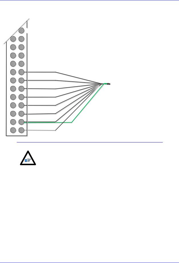
Differential Quadrature Encoder Wiring for Channel #1
J3(JMACH1)
|
25 |
24 |
23 |
22 |
21 |
20 |
19 |
18 |
17 |
16 |
15 |
14 |
13 |
12 |
11 |
10 |
9 |
8 |
7 |
6 |
5 |
4 |
3 |
2 |
1 |
C-
C+
B-
B+
A-
A+
Encoder shield
GND
+5V
For single-ended encoders, leave the complementary signal pins floating – do not ground them. Alternately, some open collector single ended encoders may require tying the negative pins to ground in series with a 1-2 KOhm resistors.
Some motor manufacturers bundle the hall sensors with the
Note |
motor-lead cable. The hall sensors must be brought into J7 |
|
connector. |
|
|
Setting up Quadrature Encoders
Digital Quadrature Encoders use the 1/T incremental entry in the encoder conversion table. Position and velocity pointers should, by default, be valid and in most cases no software setup is required, activating (Ixx00=1) the corresponding channel is sufficient to see encoder counts in the position window when the motor/encoder shaft is moved by hand.
I100,4,100 |
= 1 |
; Servo IC0 Channels 1-4 |
activated |
|
|||||
I500,4,100 |
= |
1 |
; |
Servo |
IC0 |
Channels |
5-8 |
activated |
(First Acc-1P) |
I900,4,100 |
= |
1 |
; |
Servo |
IC0 |
Channels |
9-12 activated |
(Second Acc-1P) |
|
|
|
|
|
|
|
|
|
|
|
Setting up Sinusoidal Encoders
For sinusoidal position feedback, the Acc-51S, sine wave input interpolator, stacks on top of the Turbo PMAC Clipper or on top of the Acc-1P 5-8 axis board. Channels 1 – 4 of the ACC-51S correspond to PMAC channels 1 – 4 if the ACC-51S is connected to the main Turbo PMAC Clipper; channels 1 – 4 of the ACC-51S correspond to PMAC channels 5 – 8 if the ACC-51S is connected to the ACC-1P board.
Connections and Software Setup |
22 |

Turbo PMAC Clipper Hardware Reference Manual
|
|
ACC-51S channels 1 |
– 4 become PMAC channels 1 |
– 4 if ACC- |
|
|
51S jumper E1 connects pins 2 and 3. |
|
|
|
|
ACC-51S channels 1 |
– 4 become PMAC channels 5 |
– 8 if ACC |
Note |
|
51S jumper E1 connects pins 1 and 2. |
|
|
|
|
|
|
|
|
|
|
|
|
The Sinusoidal position feedback is set up through the Encoder Conversion Table (ECT) as a high resolution interpolation entry.
Encoder Conversion Table Setup Example, Channel 1
1.Conversion Type: High res. interpolator, PMAC2 Style
2.Enter Source Address (see table below)
3.Enter A/D Converter Address (see table below)
4.A/D Bias: always zero
Channel # |
Source |
A/D converter |
|
Address |
Address |
1 |
$78000 |
$78800 |
2 |
$78008 |
$78802 |
3 |
$78010 |
$78804 |
4 |
$78018 |
$78806 |
Channel # |
Source |
A/D converter |
|
Address |
Address |
5 |
$78100 |
$78808 |
6 |
$78108 |
$7880A |
7 |
$78110 |
$7880C |
8 |
$78118 |
$7880E |
Results are found in the processed data address, which the position and velocity feedback pointers (Ixx03, Ixx04) are usually assigned to.
Note
Connections and Software Setup |
23 |

Turbo PMAC Clipper Hardware Reference Manual
The equivalent Turbo PMAC script code for 8-channel entries
// Channel 1 |
|
|
|
I8000=$FF8000 |
; High resolution interpolator |
(Clipper & Acc-51S) |
|
I8001=$078800 |
; A/D converter |
address |
(Clipper & Acc-51S) |
I8002=$000000 ; Bias Term and |
Entry result |
(Clipper & Acc-51S) |
|
// Channel 2 |
|
|
|
I8003=$FF8008 |
; High resolution interpolator |
(Clipper & Acc-51S) |
|
I8004=$078802 |
; A/D converter |
address |
(Clipper & Acc-51S) |
I8005=$000000 ; Bias Term and |
Entry result |
(Clipper & Acc-51S) |
|
// Channel 3 |
|
|
|
I8006=$FF8010 |
; High resolution interpolator |
(Clipper & Acc-51S) |
|
I8007=$078804 |
; A/D converter |
address |
(Clipper & Acc-51S) |
I8008=$000000 ; Bias Term and |
Entry result |
(Clipper & Acc-51S) |
|
// Channel 4 |
|
|
|
I8009=$FF8018 |
; High resolution interpolator |
(Clipper & Acc-51S) |
|
I8010=$078806 |
; A/D converter |
address |
(Clipper & Acc-51S) |
I8011=$000000 ; Bias Term and |
Entry result |
(Clipper & Acc-51S) |
|
// Channel 5 |
|
|
|
I8012=$FF8100 |
; High resolution interpolator |
(Acc-1P & Acc-51S) |
|
I8013=$078808 |
; A/D converter |
address |
(Acc-1P & Acc-51S) |
I8014=$000000 ; Bias Term and |
Entry result |
(Acc-1P & Acc-51S) |
|
// Channel 6 |
|
|
|
I8015=$FF8108 |
; High resolution interpolator |
(Acc-1P & Acc-51S) |
|
I8016=$07880A |
; A/D converter |
address |
(Acc-1P & Acc-51S) |
I8017=$000000 ; Bias Term and |
Entry result |
(Acc-1P & Acc-51S) |
|
// Channel 7 |
|
|
|
I8018=$FF8110 |
; High resolution interpolator |
(Acc-1P & Acc-51S) |
|
I8019=$07880C |
; A/D converter |
address |
(Acc-1P & Acc-51S) |
I8020=$000000 ; Bias Term and |
Entry result |
(Acc-1P & Acc-51S) |
|
// Channel 8 |
|
|
|
I8021=$FF8118 |
; High resolution interpolator |
(Acc-1P & Acc-51S) |
|
I8022=$07880E |
; A/D converter |
address |
(Acc-1P & Acc-51S) |
I8023=$000000 |
; Bias Term and |
Entry result |
(Acc-1P & Acc-51S) |
|
|
|
|
Position and Velocity feedback pointers should now be set to the corresponding ECT result:
I103=$3503 I104=$3503 |
; (Clipper & Acc-51S) |
||||
I203=$3506 I204=$3506 |
; (Clipper & Acc-51S) |
||||
I303=$3509 I304=$3509 |
; (Clipper & Acc-51S) |
||||
I403=$350C I404=$350C |
; (Clipper & Acc-51S) |
||||
I503=$350F |
I504=$350F |
; (Acc-1P |
& Acc-51S) |
||
I603=$3512 |
I604=$3512 |
; (Acc-1P |
& Acc-51S) |
||
I703=$3515 |
I704=$3515 |
; (Acc-1P |
& Acc-51S) |
||
I803=$3518 |
I804=$3518 |
; (Acc-1P |
& Acc-51S) |
||
|
|
|
|
|
|
|
|
|
|
|
|
At this point of the setup, you should be able to move the motor/encoder shaft by hand and see ‘motor’ counts in the position
window.
Note
Counts per User Units
With the interpolation of x 4096 in Turbo PMAC, there are 128 (4096/32) motor counts per sine/cosine cycles. Motor counts can be monitored in the motor position window upon moving the motor by hand.
Examples:
A 1024 Sine/Cosine periods per revolution of a rotary encoder produces 1024 x 128 = 131,072 cts/rev. A 20 μm linear encoder resolution produces 128/0.02 = 6400 cts/mm.
Connections and Software Setup |
24 |
Turbo PMAC Clipper Hardware Reference Manual
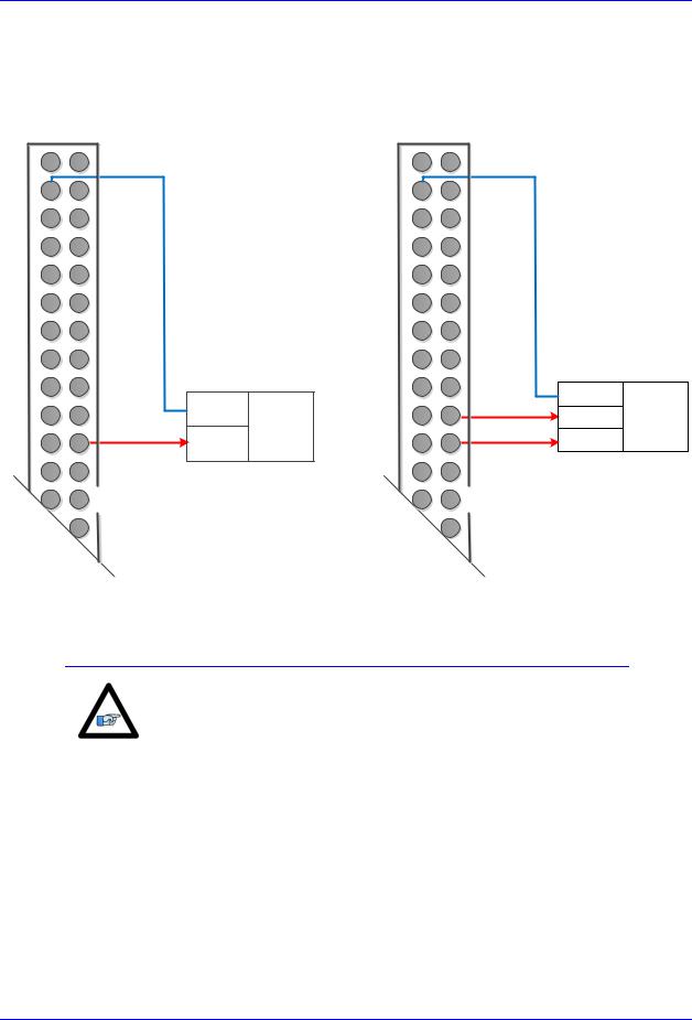
Wiring the DAC Output
Example for Clipper Channel #1
Single Ended DAC Output
50 |
49 |
|
|
48 |
47 |
|
|
46 |
45 |
|
|
44 |
43 |
|
|
42 |
41 |
|
|
40 |
39 |
|
|
38 |
37 |
|
|
36 |
35 |
|
|
34 |
33 |
|
|
32 |
31 |
COM |
Analog |
|
|||
30 |
29 |
DAC1+ Device |
|
28 |
27 |
|
|
26 |
25 |
|
|
|
23 |
|
|
J3 (JMACH1)
Differential DAC Output
50 |
49 |
48 |
47 |
46 |
45 |
44 |
43 |
42 |
41 |
40 |
39 |
38 |
37 |
36 |
35 |
34 |
33 |
32 |
31 |
30 |
29 |
28 |
27 |
26 |
25 |
|
23 |
COM
DAC1-
Analog
Device
DAC1+
J3 (JMACH1)
|
The analog outputs are intended to drive high-impedance inputs with |
|
|
no significant current draw (10mA max). The 220 output resistors |
|
|
will keep the current draw lower than 50 mA in all cases and prevent |
|
Note |
damage to the output circuitry, but any current draw above 10 mA can |
|
result in noticeable signal distortion. |
||
|
||
|
|
Connections and Software Setup |
25 |
 Loading...