

Page 1

^1 HARDWARE REFERENCE MANUAL
UMAC Turbo CPU/Communications Board
^3 HRM for UMAC Turbo CPU/Communications Board
^4 3xx-603766-xHxx
^5 April 26, 2012
Single Source Machine Control Power // Flexibility // Ease of Use
21314 Lassen Street Chatsworth, CA 91311 // Tel. (818) 998-2095 Fax. (818) 998-7807 // www.deltatau.com
i
Page 2

Copyright Information
© 2009 Delta Tau Data Systems, Inc. All rights reserved.
This document is furnished for the customers of Delta Tau Data Systems, Inc. Other uses
are unauthorized without written permission of Delta Tau Data Systems, Inc.
Information contained in this manual may be updated from time-to-time due to product
improvements, etc., and may not conform in every respect to former issues.
To report errors or inconsistencies, call or email:
Delta Tau Data Systems, Inc. Technical Support
Phone: (818) 717-5656
Fax: (818) 998-7807
Email: support@deltatau.com
Website: http://www.deltatau.com
Operating Conditions
All Delta Tau Data Systems, Inc. motion controller products, accessories, and amplifiers
contain static sensitive components that can be damaged by incorrect handling. When
installing or handling Delta Tau Data Systems, Inc. products, avoid contact with highly
insulated materials. Only qualified personnel should be allowed to handle this
equipment.
In the case of industrial applications, we expect our products to be protected from
hazardous or conductive materials and/or environments that could cause harm to the
controller by damaging components or causing electrical shorts. When our products are
used in an industrial environment, install them into an industrial electrical cabinet or
industrial PC to protect them from excessive or corrosive moisture, abnormal ambient
temperatures, and conductive materials. If Delta Tau Data Systems, Inc. products are
exposed to hazardous or conductive materials and/or environments, we cannot guarantee
their operation.
ii
Page 3

REVISION UPDATE
REV.
DESCRIPTION
DATE
CHG
APPVD
1
Added CE declaration of conformity
08/24/06
CP
S. Fierro
2
USB/Ethernet Description, P.14, 19, 23
05/07/07
CP
S. Milici
3
Watchdog Terminal Block Info
10/12/07
CP
S. Milici
4
Corrections to J8 Table, P.17
06/13/08
CP
S.Sattari
5
Added UL Approval Logo on manual cover
Updated Agency Approval &Safety Section
09/29/09
CP
S. Fierro
6
E12 default jumper settings should be "no jumper installed"
10/08/10
S.S
S. Sattari
7
Added Jumper E1
01/05/12
M.Y
R.Naddaf
8
Clarified E1 and E6 jumper description
04/26/12
Sgm
S. Milici
iii
Page 4

TABLE OF CONTENTS
Copyright Information ............................................................................................................................................ ii
Operating Conditions.............................................................................................................................................. ii
INTRODUCTION ................................................................................................................................................ 1
Upgrade Issues ....................................................................................................................................................... 1
Board Configuration ............................................................................................................................................... 2
Base Version ...................................................................................................................................................... 2
Option 2B: Dual-Ported RAM ........................................................................................................................... 2
Option 5: CPU and Memory Configurations ...................................................................................................... 2
Option 8: High-Accuracy Clock Crystal ............................................................................................................. 3
Option 10: Firmware Version Specification ....................................................................................................... 3
Option 16A: Battery-Backed Parameter Memory ............................................................................................... 3
Connectors and Indicators....................................................................................................................................... 3
J7 – Main Serial Port (RS-232 Port) ................................................................................................................... 3
J8 – Auxiliary Serial Port (RS-232 Port) ............................................................................................................. 3
J9 – USB Port .................................................................................................................................................... 3
J10 – Ethernet Port ............................................................................................................................................ 3
TB1 – Watchdog Relay ....................................................................................................................................... 3
LED Indicators................................................................................................................................................... 3
Dimensions and Layout ................................................................................................................................ .......... 4
SPECIFICATIONS ................................................................................................ .............................................. 5
Environmental Specifications ................................................................................................................................. 5
Physical Specifications ........................................................................................................................................... 5
Electrical Specifications ......................................................................................................................................... 6
Agency Approval and Safety ................................ ................................................................................................ .. 6
JUMPER SETUP SUMMARY ............................................................................................................................ 7
Clock Source Jumpers ............................................................................................................................................ 7
Watchdog Timer Jumper ........................................................................................................................................ 7
Operation Mode Jumpers ........................................................................................................................................ 7
Firmware Reload Jumper ........................................................................................................................................ 7
Re-Initialization Jumper ......................................................................................................................................... 7
Reference Voltage Connect Jumper ........................................................................................................................ 8
Interrupt Select Jumpers ......................................................................................................................................... 8
Flash Memory Bank Select Jumpers ....................................................................................................................... 8
PC/104 Bus Use Selection ...................................................................................................................................... 8
USB/Ethernet Firmware Reload Jumpers ................................................................................................................ 8
CONNECTIONS .................................................................................................................................................. 9
Backplane (UMAC) Connections............................................................................................................................ 9
PC/104 Connections ............................................................................................................................................... 9
Serial Port Connections .......................................................................................................................................... 9
USB Type B Receptacle ................................ ................................................................................................ ....... 10
J6: Ethernet RJ45 Connector ................................................................................................................................. 10
BOARD JUMPERS ............................................................................................................................................ 11
E0: Factory Use Only .......................................................................................................................................... 11
E1: Write Enable Protect for USB/Ethernet Communication Firmware ................................................................. 11
E1A: Servo and Phase Clock Direction Control.................................................................................................... 11
E1B: Servo/Phase Clock Source Control .............................................................................................................. 11
E2: Reserved for Future Use ................................................................................................................................ 11
E3: Re-Initialization on Reset Control .................................................................................................................. 11
E4: Reserved for Future Use ................................................................................................................................ 11
E5: Port Select ..................................................................................................................................................... 12
E6: USB/Ethernet Micro-Controller Reset Enable ................................................................................................ 13
E7 – E10: IRQ PC Interrupt Select ....................................................................................................................... 13
iv
Page 5

E12: Digital/Analog Reference Connect ............................................................................................................... 13
E17 – E18: Serial Port Servo and Phase Clocks Enable ........................................................................................ 13
E19: Watchdog Disable Jumper ........................................................................................................................... 14
E20 – E22: Power-Up/Reset Load Source ............................................................................................................ 14
E23: Firmware Reload Enable ............................................................................................................................. 14
E25A – E25C: Flash Memory Bank Select ........................................................................................................... 14
DIP Switch Block S1: PC Bus Base Address ................................ ........................................................................ 15
CONNECTOR SUMMARY............................................................................................................................... 16
BOARD CONNECTOR PINOUTS ................................................................................................................... 18
J7: Primary Serial Port Connector (RS232) .......................................................................................................... 18
J8: Auxiliary Serial Port Connector (RS232) ........................................................................................................ 18
J9: Universal Serial Bus Port (USB)..................................................................................................................... 18
J10: Ethernet Port ................................................................................................................................................ 19
TB1: 2-Pin Terminal Block.................................................................................................................................. 19
ETHERNET SOFTWARE SETUP ................................................................................................................... 20
IP Setup ............................................................................................................................................................... 20
Protocol Setup ................................ ................................................................................................ ...................... 21
Windows OS TCP/IP Setup .................................................................................................................................. 22
Determining if TCP/IP is Setup Correctly ............................................................................................................. 23
USB SOFTWARE SETUP ................................................................................................................................. 24
Device Driver Installation ................................ ................................................................................................ ..... 24
PEWIN PRO SOFTWARE SETUP ................................................................................................................... 26
First Time User (Register the Newly Installed Devices) ........................................................................................ 26
USING DPRAM ................................................................................................................................................. 28
DPRAM for General Purpose Scratch Pad Data .................................................................................................... 28
Setting DPRAM for Automatic Reporting Features ............................................................................................... 28
UPGRADING COMMUNICATIONS FIRMWARE ........................................................................................ 30
Upgrading Ethernet or USB Firmware .................................................................................................................. 30
UMAC-Turbo Memory Mapping ................................................................................................ .......................... 30
Using the USB DPRAM ....................................................................................................................................... 30
Getting the Best Performance from USB ............................................................................................................... 31
ETHERNET PROTOCOL ................................................................................................................................. 32
Ethernet Protocol Command Packet Description ................................................................................................... 32
Command Packets ................................................................ ............................................................................ 32
Ethernet Protocol Command Set ........................................................................................................................... 33
VR_PMAC_FLUSH .......................................................................................................................................... 33
VR_PMAC_SENDLINE .................................................................................................................................... 33
VR_PMAC_GETLINE ................................................................................................ ...................................... 34
VR_PMAC_GETBUFFER ................................................................................................................................ 35
VR_ IPADDRESS ............................................................................................................................................. 35
VR_PMAC_SENDCTRLCHAR ......................................................................................................................... 35
VR_PMAC_PORT ............................................................................................................................................ 36
VR_PMAC_READREADY ................................................................................................................................ 36
VR_CTRL_REPONSE ...................................................................................................................................... 36
VR_PMAC_WRITEBUFFER ............................................................................................................................ 37
VR_FWDOWNLOAD ....................................................................................................................................... 37
VR_PMAC_GETRESPONSE ............................................................................................................................ 37
VR_PMAC_GETMEM ................................ ................................................................................................ ...... 38
VR_PMAC_SETMEM....................................................................................................................................... 38
VR_PMAC_SETBIT ......................................................................................................................................... 38
VR_PMAC_SETBITS........................................................................................................................................ 39
v
Page 6

OPTION 16: BATTERY BACKED MEMORY ................................................................................................ 40
Safety and Handling of Lithium Batteries ............................................................................................................. 40
DECLARATION OF CONFORMITY .............................................................................................................. 42
APPENDIX ......................................................................................................................................................... 43
Previous revisions Board Dimensions and Layout — Part Number 603766-100 through -102 ................................ 43
vi
Page 7

UMAC Turbo CPU/Communications Board Hardware Manual
INTRODUCTION
The UMAC (Universal Motion and Automation Controller) is a modular system built with a set of 3Uformat Eurocards. The configuration of any UMAC system starts with the selection of the UMAC Turbo
CPU/Communications Board and continues with the addition of the necessary axes boards, I/O boards,
and any other interface boards selected from a variety of available accessories.
The UMAC Turbo CPU/Communications Board (part number 3x0-603766-10x) is a member of the
Turbo PMAC2 family of boards. It is software is capable of 32 axes of control. Accessory boards
installed in the UMAC Turbo system interface between the UMAC Turbo CPU/Communications Board
and the machine to output amplifier command signals, to input feedback information, and to input flags
information including end-of-travel limits and machine home sensors. Different kind of axes interface
boards can be selected to control analog ±10V amplifiers, stepper drivers and direct digital PWM
amplifiers.
Several methods of communications can be implemented between the UMAC Turbo System and the host
computer. These methods include two RS-232 serial ports, USB, Ethernet and PC/104 bus
communications. The UMAC Turbo CPU/Communications Board can communicate at the same time
with the two RS-232 ports, USB or Ethernet ports. However, if PC/104 bus communications is used, the
USB or Ethernet ports cannot be used.
Upgrade Issues
The UMAC Turbo CPU/Communications Board can be used to replace both the older UMAC CPU board
(part number 3x0-603382-10x) and the Acc-54E USB/Ethernet communications board (part number 3x0603467-10x). Combining both of these functions onto a single board saves both money and rack space.
The UMAC Turbo CPU/Communications Board supports high-speed CPUs (160 MHz and 240 MHz)
than the older UMAC CPU board, but it also supports the 80 MHz and 100 MHz configurations of the old
board.
Usually, use of the UMAC Turbo CPU/Communications Board is compatible with older UMAC CPU
board and Acc-54E communications board. However, the base address of the DPRAM IC on the
CPU/Communications Board is $060000, whereas the base address of the DPRAM on the Acc-54E is
higher ($06C000 by default).
Setup variable I24 should be set to $060000 (or $0) to use the automatic functions in the on-board DPRAM
IC. Any M-variable used for DPRAM registers should be in the $060000 - $0603FFF address range.
The following list summarizes the differences with respect to the older version:
Addition of on-board USB and Ethernet
Support for 160 MHz and 240 MHz CPUs (Opt 5Ex and 5Fx)
Main serial connector reduced to 10-pins and RS-232 only
Elimination of upward stack connectors for axis boards
Addition of watchdog timer relay
Elimination of voltage interlock circuit
Introduction 1
Page 8

UMAC Turbo CPU/Communications Board Hardware Manual
Board Configuration
Base Version
The base version of the UMAC Turbo CPU/Communications Board without options provides a single
board 160 mm wide and 100 mm high for a 20 mm slot with:
80 MHz DSP56303 CPU (120 MHz PMAC equivalent) (fast internal memory for first 15 axes servo
and commutation)
128k x 24 SRAM compiled/assembled program memory (5C0) (for firmware, compiled PLCs, user-
written servo and phase)
128k x 24 SRAM user data memory (5C0) (for motion and uncompiled PLC programs, variables,
tables, and buffers)
1M x 8 flash memory for user backup & firmware (5C0) version
Latest released firmware
100 Mbit/sec UDP/IP, TCP/IP Ethernet Communications Interface
480 Mbit/sec USB 2.0 Communications Interface (USB 1.1 compatible)
Two RS-232 serial interfaces with IDC 10-pin front connector
PID/notch/feedforward servo algorithms
Extended pole-placement servo algorithms
1-year warranty from date of shipment (External cables not included)
Option 2B: Dual-Ported RAM
Dual-ported RAM provides a high-speed communications path for bus communications with the host
computer through a bank of shared memory. DPRAM is advised if more than 100 data items per second
will be passed between the controller and the host computer in either direction.
Option 2B provides the Dual-Ported RAM for PC/104, USB, or Ethernet interface
Option 5: CPU and Memory Configurations
The various versions of Option 5 provide different CPU speeds and main memory sizes. Only one Option
5xx may be selected for the board.
Option 5C0 is the standard CPU and memory configuration. It is provided automatically if no Option
5xx is specified. It provides an 80 MHz DSP56303 CPU w/8Kx24 internal memory, 128Kx24
SRAM compiled/ assembled program memory, 128Kx24 SRAM user data memory, 1Mx8 flash
memory.
Option 5C3 provides an 80 MHz DSP56303 CPU w/8Kx24 internal memory, expanded 512Kx24
SRAM compiled/assembled program memory, expanded 512Kx24 SRAM user data memory, 4Mx8
flash memory.
Option 5D0 provides a 100 MHz DSP56309 CPU w/34Kx24 internal memory, 128Kx24 SRAM
compiled/ assembled program memory, 128Kx24 SRAM user data memory, 1Mx8 flash memory.
Option 5D3 provides a 100 MHz DSP56309 CPU w/34Kx24 internal memory, expanded 512Kx24
SRAM compiled/assembled program memory, expanded 512Kx24 SRAM user data memory, 4Mx8
flash memory.
Option 5E0 provides a 160 MHz DSP56311 CPU w/128Kx24 internal memory, 128Kx24 SRAM
compiled/ assembled program memory, 128Kx24 SRAM user data memory, and 1Mx8 flash
memory. Requires V1.939 or newer firmware.
Option 5E3 provides a 160 MHz DSP56311 CPU w/128Kx24 internal memory, expanded 512Kx24
SRAM compiled/assembled program memory, expanded 512Kx24 SRAM user data memory, and
4Mx8 flash memory. Requires V1.939 or newer firmware.
Introduction 2
Page 9

UMAC Turbo CPU/Communications Board Hardware Manual
Option 5F0 provides a 240 MHz DSP56321 CPU w/192Kx24 internal memory, 128Kx24 SRAM
compiled/ assembled program memory, 128Kx24 SRAM user data memory, and 1Mx8 flash
memory. Requires V1.940 or newer firmware.
Option 5F3 provides a 240MHz DSP56321 CPU w/192Kx24 internal memory, expanded 512Kx24
SRAM compiled/assembled program memory, expanded 512Kx24 SRAM user data memory, and
4Mx8 flash memory. Requires V1.940 or newer firmware.
Option 8: High-Accuracy Clock Crystal
The UMAC Turbo CPU/Communications Board has a clock crystal of nominal frequency 19.6608 MHz
(~20 MHz). The standard crystal’s accuracy specification is ±100 ppm.
Option 8A provides a nominal 19.6608 MHz crystal with a ±15 ppm accuracy specification.
Option 10: Firmware Version Specification
Normally, the UMAC Turbo CPU/Communications Board is provided with the newest released firmware
version. A label on the flash memory IC shows the firmware version loaded at the factory.
Option 10 provides for a user-specified firmware version.
Option 16A: Battery-Backed Parameter Memory
The contents of the standard memory are not retained through a power-down or reset unless they have been
saved to flash memory first. Option 16A provides supplemental battery-backed RAM for real-time
parameter storage that is ideal for holding machine state parameters in case of an unexpected power-down.
Option 16A provides a 32k x 24 bank of battery-backed parameter RAM.
Connectors and Indicators
J7 – Main Serial Port (RS-232 Port)
J7 is the primary serial communications port. For serial communications, use a serial cable to connect the
PC’s COM port to the board’s serial port connector. Delta Tau provides the Acc-3L cable to connect the
UMAC Turbo CPU/Communications Board to a DB 9 connector.
J8 – Auxiliary Serial Port (RS-232 Port)
J8 is the auxiliary serial communications port. For serial communications, use a serial cable to connect
the PC’s COM port to the board’s serial port connector. Delta Tau provides the Acc-3L cable to connect
UMAC Turbo CPU/Communications Board to a DB 9 connector.
J9 – USB Port
This connector is used in conjunction with USB A-B cable which can be purchased from any local
computer store, and is provided when Option 1A is ordered. The A connector is connected to a PC or
Hub device; the B connector plugs into the J9-USB port.
J10 – Ethernet Port
This connector is used for Ethernet communications from the UMAC Turbo CPU/Communications Board
to a PC.
TB1 – Watchdog Relay
In case of watchdog failure, the contacts of a relay present on this connector will change state.
LED Indicators
When lit, the D1 Red LED indicates a watchdog failure.
When lit, the D2 Green LED indicates that the 5V power supply is applied to the board.
When lit, the D8 Green LED indicates that a USB or Ethernet cable is plugged in and ready to
establish communications.
Introduction 3
Page 10
UMAC Turbo CPU/Communications Board Hardware Manual
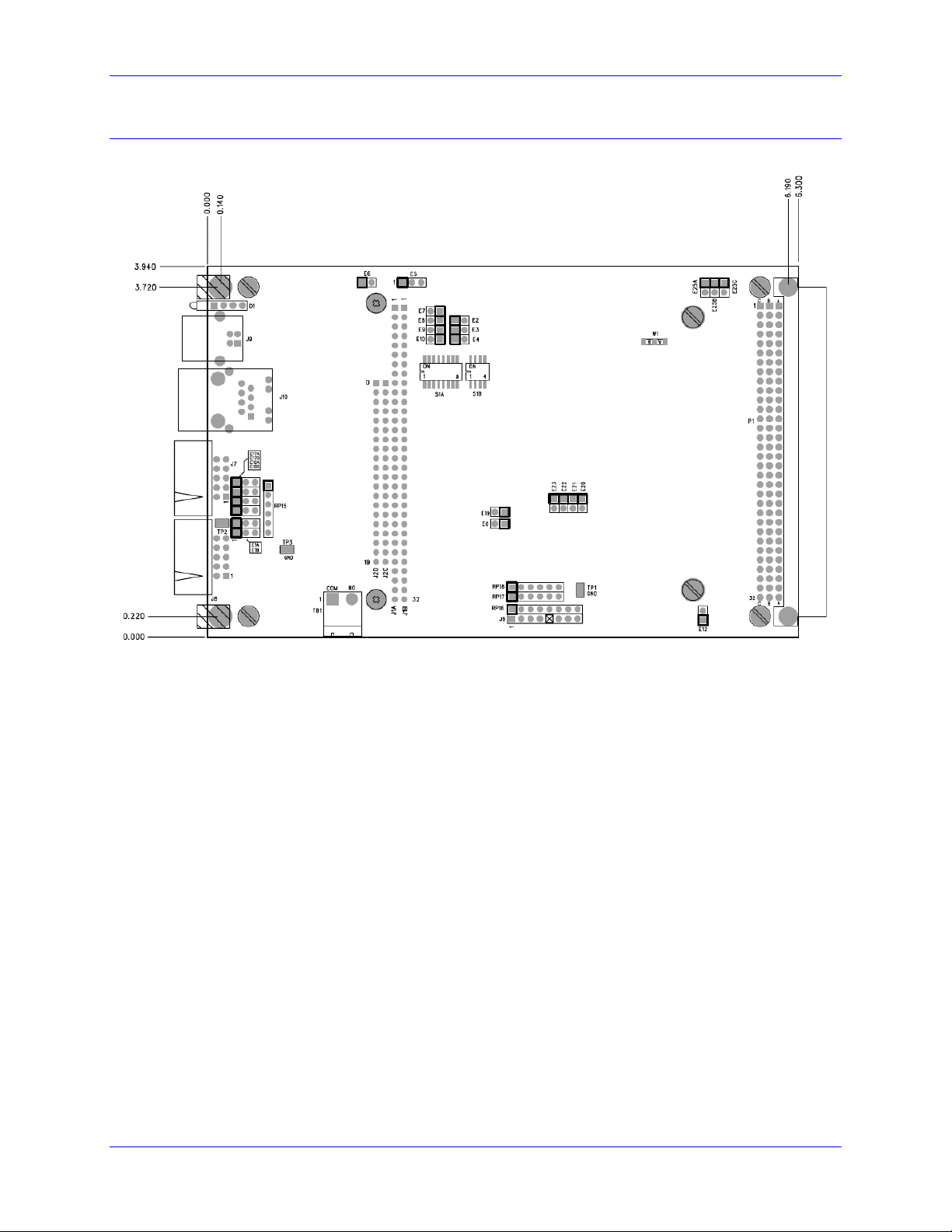
Dimensions and Layout
Part Number 603766-103 and newer
Introduction 4
Page 11

UMAC Turbo CPU/Communications Board Hardware Manual
Description
Specification
Notes
Operating Temperature
0°C to 45°C,
Storage Temperature
-25°C to 70°C
Humidity
10% to 95 % non-condensing
Description
Specification
Notes
Dimensions w/o PC/104 Option
Length: 16.256 cm (6.4 in.)
Height: 10 cm (3.94 in.)
Width: 3.05 cm (1.2 in.)
Dimensions with PC/104 Option
Length: 16.256 cm (6.4 in.)
Height: 10 cm (3.94 in.)
Width: 2.03 cm (0.8 in.)
Weight
170 g
Front Plate included
The width is the width of the front plate. The length and height are the dimensions of the PCB.
SPECIFICATIONS
Environmental Specifications
Physical Specifications
Jumpers Setup Summary 5
Page 12

UMAC Turbo CPU/Communications Board Hardware Manual
Description
Specification
Notes
Power Requirements
5V @ 1.0A (10%)
Option 16 Battery
Size: PC
Type: Lithium
Voltage: 3.6V
Rated Capacity: 1.0 Ah
ElectroChem QTC85
series lithium battery
part number 3B880.
Item
Description
CE Mark
Full Compliance
EMC
EN55011 Class A Group 1
EN61000-3-2 Class A
EN61000-3-3
EN61000-4-2
EN61000-4-3
EN61000-4-4
EN61000-4-5
EN61000-4-6
EN61000-4-11
Safety
EN 61010-1
UL
UL 61010-1 File E314517
cUL
CAN/CSA C22.2 No. 1010.1-92 File E314517
Flammability Class
UL 94V-0
Electrical Specifications
Agency Approval and Safety
Jumpers Setup Summary 6
Page 13

UMAC Turbo CPU/Communications Board Hardware Manual
JUMPER SETUP SUMMARY
On the UMAC Turbo CPU/Communications Board, there are many jumpers (pairs of metal prongs),
called E-points. Some have been shorted together; others have been left open. These jumpers customize
the hardware features of the board for a given application and must be set up appropriately. The
following is an overview of the several UMAC Turbo CPU/Communications Board jumpers.
Clock Source Jumpers
In order to operate, the board must receive servo and phase clock signals from a source external to the
board. These clock signals can be brought into the board from one of two possible ports: the UBUS
backplane connector, or the front-side main serial-port connector. Jumpers E1A and E1B must be
configured properly for the clock source used.
To receive the clock signals over the UBUS backplane, usually from an Acc-24E2x axis-interface board
or an Acc-5E MACRO-interface board, E1A must connect pins 1 and 2, and E1B must connect pins 2 and
3. Use this default setup in most cases.
To receive the clock signals through the main serial port, usually from another PMAC system or a
reference signal generator, E1A must connect pins 2 and 3 and E1B must connect pins 1 and 2. Though
rarely used, this configuration permits complete synchronization to the system that is generating the clock
signals.
To either input or output the clock signals through the J7 serial port, jumpers E17A, E17B, E18A, and
E18B must be configured in positions 2-3. Otherwise, these jumpers must be set at position 1-2.
Watchdog Timer Jumper
Jumper E19 should be OFF for normal operation, leaving the watchdog timer circuit active and prepared
to shut down the card in case of a severe problem. Putting jumper E19 ON disables the watchdog timer
circuit. This should be used for test purposes only to try to track down the source of watchdog timer trips.
Normal operation of a system with this jumper ON should never be attempted, as an important safety
feature is disabled.
Operation Mode Jumpers
Jumpers E20, E21, and E22 control the operational mode of the UMAC Turbo CPU/Communications
Board. For normal operation, E20 must be OFF, E21 must be ON, and E22 must be ON. Other settings
of these jumpers are for factory use only.
Firmware Reload Jumper
Jumper E23 should be OFF for normal operation. To load new firmware into the flash-memory IC on the
CPU, E23 should be ON when the card is powered up. This puts the card in bootstrap mode, and ready to
accept a new firmware. Then try to establish communications to the card with the Executive program, the
Executive program will recognize that the card is in bootstrap mode automatically, and prompt for the
firmware file to download.
Re-Initialization Jumper
If jumper E3 is installed when the board is powered-up or reset, the board firmware will go through a reinitialization process, returning most I-variables to factory default values. The last saved values are not
lost when this happens. It will also go through a system auto-detection process, selecting which of the
Servo ICs that it finds will be the source of the servo and phase clock signals for the system. Typically,
this jumper is used only when the system’s setup has a problem severe enough that communications does
not work – otherwise, a $$$*** command can be used for re-initialization.
Jumpers Setup Summary 7
Page 14

UMAC Turbo CPU/Communications Board Hardware Manual
Reference Voltage Connect Jumper
Jumper E12 permits the reference voltage for the analog and digital circuits in the UMAC Turbo
CPU/Communications Board to be tied together. If not isolating the analog circuits from the digital
circuits, this jumper should be ON. If isolating the analog circuits from the digital circuits using separate
isolated supplies for the two circuits, this jumper should be OFF.
Interrupt Select Jumpers
If the PC/104-bus interface is installed, the UMAC Turbo CPU/Communications Board can interrupt the
PC/104 host computer over one of four interrupt lines as selected by jumpers E7 – E10. One of these
jumpers should be ON in any configuration.
E7 ON selects interrupt line IRQ10
E8 ON selects interrupt line IRQ11
E9 ON selects interrupt line IRQ12
E10 ON selects interrupt line IRQ15
Flash Memory Bank Select Jumpers
The flash-memory IC has the capacity for eight separate banks of firmware, only one of which can be
used at any given time. The eight combinations of settings for jumpers E25A, E25B, and E25C select
which bank of the flash memory is used. In the factory production process, firmware is loaded only into
Bank 0, which is selected by having all of these jumpers OFF.
PC/104 Bus Use Selection
If the PC/104 bus communications method is used, jumper E5 must be installed in position 1-2. If the
USB or Ethernet communications ports are used, jumper E5 must be installed in position 2-3.
USB/Ethernet Firmware Reload Jumpers
Jumper E1 should be OFF to engage the “Write Protect” feature. This is the default factory shipped
setting. To load new firmware into the USB/Ethernet micro-controller jumper E1 must be installed to
disable “Write Protect”.
Jumper E6 should be ON for normal operation. Jumper E6 should only be removed when directed by a
Delta Tau Technical Support Engineer to reset the USB/Ethernet processor. To do so jumper E6 should
be removed (OFF) before the card is powered; this puts the on-board USB/Ethernet micro-controller in
bootstrap mode. After power-on the jumper must be replaced (ON) to allow writing to the microcontroller to accept new firmware (as well as setting ON the E1 jumper).
Note:
The jumper E1 may be left in the ON position but this will disable the “Write
Protect” feature.
Jumpers Setup Summary 8
Page 15

UMAC Turbo CPU/Communications Board Hardware Manual
CONNECTIONS
Backplane (UMAC) Connections
To connect the UMAC Turbo CPU/Communications Board to the UBUS backplane, simply insert the P1
connector into one of the sockets on an Acc-Ux UBUS backplane board. It does not matter which socket
on the UBUS backplane board is used, although customarily, the CPU board is installed in the leftmost
slot. Typically, the backplane board will have been installed already in a Eurorack frame (Acc-Px or
equivalent), so the CPU board is simply slid into one of the slot guides in the frame until it mates with the
backplane board; then the front-plate screws are tightened for a firm connection to the rack and
backplane.
If a power supply has been connected to the UBUS backplane board, this power will be supplied
automatically to the Turbo CPU board. The UBUS backplane board is capable of supplying isolated
analog and digital supplies, but the 3U-format power supplies (Acc-Ex) provided by Delta Tau do not
keep these two supplies isolated from each other.
PC/104 Connections
If the PC/104 connector is installed, the UMAC Turbo CPU/Communications Board may be mounted on
the top of a PC/104 stack. Because it does not pass the connector through, it may be mounted only on the
top of such a stack. The UMAC Turbo CPU/Communications Board has four mounting holes in the
standard PC/104 locations for standoff connections to the PC/104 stack. Note that the PC/104 connector
used on the UMAC Turbo CPU/Communications Board provides for the Eurocard 4T standard of 20 mm
(0.8”) spacing between boards, not the PC/104 standard of 15mm (0.6”), so standoff lengths must be
chosen accordingly.
Serial Port Connections
The standard J7 serial-port connector on the front edge of the UMAC Turbo CPU/Communications Board
is an IDC 10-pin header. The connector is designed so that a standard flat-cable connection (such as a
Delta Tau Acc-3L cable) to a DB-9 connector can be used. From there, a standard DB25-to-DB9 adapter
can be used if necessary. The servo and phase clock signals can be either input or output on this
connector, depending on the setting of jumpers E1A, E1B, E17A, E17B, E18A and E18B.
The auxiliary J8 serial-port connector is also an IDC 10-pin header. The connector is designed so that a
standard flat-cable connection (such as a Delta Tau Acc-3L cable) to a DB-9 connector can be used.
From there, a standard DB9-to-DB25 adapter can be used, if necessary.
Connections 9
Page 16

UMAC Turbo CPU/Communications Board Hardware Manual
USB Type B Receptacle
This connector is used in conjunction with USB A-B cable which can be purchased from any local
computer store. The A connector is connected to a PC or Hub device; the B connector plugs into the
UMAC Turbo CPU/Communications Board. The picture below displays what the two ends on the cable
should look like.
This connector is used to communicate with the host PC through a USB connection. In addition, this
connector is used to install and upgrade the micro-controller Ethernet firmware and to program the static
Internet Protocol (IP) address into an EEPROM that is read on startup. Do not attach a cable to this
connector when communicating to the board via Ethernet.
The maximum cable length according to the USB Specification 2.0 for a full speed cable is 5 m (~15ft).
According to the USB specification, up to five USB cables can be connected together with a hub, to
create a maximum length of 30 m (~98ft). In addition, to extend the length of the USB connection there
are USB active extension cables available. Use a USB cable of high quality. Using higher quality USB
cables, some systems have operated up to 10 m (30ft) cables without the use of an active extension cable
or hub. However, violating the specification by running a cable more than 5m is not recommended or
guaranteed.
J6: Ethernet RJ45 Connector
This connector is used for Ethernet communications from the UMAC to a PC. The appropriate Category
5 10/100-Base T network cable that mates to this connector can be purchased from any local computer
store. The type of network cable to purchase depends on the configuration to the host PC.
When making a direct connection to a Host communication Ethernet card in a PC, a Category 5
networking crossover cable must be used. A standard Category 5 straight through networking cable
cannot be used in this scenario. See left section of the following diagram.
When using a connection to a network Hub or switch, the standard Category 5 straight through
networking cable must be used, and not a crossover cable. See right section of the figure below.
Performance can be degraded by the use of a hub or switch. Network hubs or the more intelligent
network switches have processors inside them which can add delays of at least 15 msec to the UMAC
communications.
Connections 10
Page 17

UMAC Turbo CPU/Communications Board Hardware Manual
E Point and
Physical Layout
Description
Default
Remove jumper for normal operation. User cannot change IP or
upload communication firmware in this mode.
Jump pins 1 to 2 to enable IP change and uploading USB/Ethernet
communication firmware.
No jumper installed
E Point and
Physical Layout
Description
Default
Jump pins 1 and 2 to use its internally generated servo and phase
clock signals and to output these signals on the J7 serial port
connector. E1B should connect pins 2 and 3.
Jump pins 2 and 3 for the UMAC Turbo system to expect to
receive its servo and phase clock signals on the J7 serial port
connector. E1B should also connect pins 1 and 2.
See also jumpers E17A, E17B, E18A, and E18B
Pins 1-2 jumpered
E Point and
Physical Layout
Description
Default
Jump pin 1 to 2 to get phase and servo clocks from J7 serial port
connector (from an external source such as another PMAC).
Jump pin 2 to 3 to get phase and servo clocks from P1 backplane
connector (from an Acc-24E2x, or equivalent board).
Pins 2-3 jumpered
E Point and
Physical Layout
Description
Default
Remove jumper for normal reset mode (default).
Jump pins 1 to 2 for re-initialization on reset.
No jumper installed
BOARD JUMPERS
E0: Factory Use Only
E1: Write Enable Protect for USB/Ethernet Communication Firmware
E1A: Servo and Phase Clock Direction Control
E1B: Servo/Phase Clock Source Control
E2: Reserved for Future Use
E3: Re-Initialization on Reset Control
E4: Reserved for Future Use
Board Jumpers 11
Page 18

UMAC Turbo CPU/Communications Board Hardware Manual
E Point and
Physical Layout
Description
Default
Jump pin 1 to 2 to use the PC/104 bus communications.
Jump pin 2 to 3 to use USB or Ethernet communication ports.
Pins 2-3 jumpered
E5: Port Select
Board Jumpers 12
Page 19

UMAC Turbo CPU/Communications Board Hardware Manual
E Point and
Physical Layout
Description
Default
Remove jumper to reset USB/Ethernet Micro-Controller on powerup\reset – replace after power-on.
Install jumper for normal operations.
Pins 1-2 jumpered
E Point and
Physical Layout
Description
Default
E7:
Jump E7 pin 1 to 2 to permit UMAC to interrupt PC on PC/104 bus
interrupt line IRQ10.
Remove E7 jumper to inhibit interrupt capability on this line.
No jumper installed
E8:
Jump E8 pin 1 to 2 to permit UMAC to interrupt PC on PC/104 bus
interrupt line IRQ11.
Remove E8 jumper to inhibit interrupt capability on this line.
No jumper installed
E9:
Jump E9 pin 1 to 2 to permit UMAC to interrupt PC on PC/104 bus
interrupt line IRQ12.
Remove E9 jumper to inhibit interrupt capability on this line.
No jumper installed
E10:
Jump E10 pin 1 to 2 to permit UMAC to interrupt PC on PC/104
bus interrupt line IRQ15.
Remove E10 jumper to inhibit interrupt capability on this line.
No jumper installed
E Point and
Physical Layout
Description
Default
Jump pin 1 to 2 to tie digital GND reference to analog AGND
reference when using joint supply (e.g. from TB1 or PC/104).
Remove jumper to maintain separate GND and AGND reference
voltages to keep isolation when using separate supplies.
No jumper installed
E Point and
Physical Layout
Description
Default
E17A:
Jump E17A pin 1 to 2 to disable PHASE+ on J7 serial port.
Jump E17A pin 2 to 3 to enable PHASE+ on J7 serial port.
Pins 1-2 jumpered
E17B:
Jump E17B pin 1 to 2 to disable PHASE- on J7 serial port.
Jump E17B pin 2 to 3 to enable PHASE- on J7 serial port.
Pins 1-2 jumpered
E18A:
Jump E18A pin 1 to 2 to disable SERVO+ on J7 serial port.
Jump E18A pin 2 to 3 to enable SERVO+ on J7 serial port.
Pins 1-2 jumpered
E18B:
Jump E18B pin 1 to 2 to disable SERVO- on J7 serial port.
Jump E18B pin 2 to 3 to enable SERVO- on J7 serial port.
Pins 1-2 jumpered
E6: USB/Ethernet Micro-Controller Reset Enable
E7 – E10: IRQ PC Interrupt Select
E12: Digital/Analog Reference Connect
E17 – E18: Serial Port Servo and Phase Clocks Enable
Board Jumpers 13
Page 20

UMAC Turbo CPU/Communications Board Hardware Manual
E Point and
Physical Layout
Description
Default
Jump pin 1 to 2 to disable Watchdog timer (for test purposes only).
Remove jumper to enable Watchdog timer.
No jumper installed
E Point &
Physical Layout
Description
Default
E20:
To load active memory from flash IC on power-up/reset/remove
jumper E20;
Jump E21 pin 1 to 2
Jump E22 pin 1 to 2.
Other combinations are for factory use only; the board will not
operate in any other configuration.
No E20 jumper
installed
E21 and E22, jump
pin 1 to 2.
E21:
E22:
E Point and
Physical Layout
Description
Default
Install jumper to reload firmware through the communications port.
Remove jumper for normal operations.
No jumper installed
E Point and
Physical Layout
Description
Default
E25A:
Remove all three jumpers to select flash memory bank with factoryinstalled firmware.
Use other configuration to select one of the seven other flash
memory banks.
No jumpers installed
E25B:
E25C:
E19: Watchdog Disable Jumper
E20 – E22: Power-Up/Reset Load Source
E23: Firmware Reload Enable
E25A – E25C: Flash Memory Bank Select
Board Jumpers 14
Page 21

UMAC Turbo CPU/Communications Board Hardware Manual
S1B
S1A
4 3 2 1 8 7 6 5 4 3 2
1
OFF
OFF
OFF
OFF
OFF
OFF
OFF
OFF
OFF
OFF
OFF
OFF
ON
ON
ON
ON
ON
ON
ON
ON
ON
ON
ON
ON
The 12 DIP switches on block S1 set the base address of the UMAC Turbo CPU/Communications Board on the PC/104 bus.
Together they form a binary number. Each switch, if in the ON (closed) position, sets its bit to 0; if in the OFF (open)
position, sets its bit to 1. The possible base addresses are all multiples of 16, so switch 1 sets a bit value of 16, switch 2 sets a
bit value of 32, and so on. According to the following table, the default settings provide a base address of 528 (210h).
Note that for proper USB/Ethernet communication the host address must be set to this default value.
S1A Switch #
Bit Value
Default
Default Value
S1B Switch #
Default
Default Value
1
16 (10h)
OFF (x1)
16 (10h)
1
4096 (1000h)
0
2
32 (20h)
ON (x0) 0 2
8192 (2000h)
0
3
64 (40h)
ON (x0) 0 3
16384 (4000h)
0
4
128 (80h)
ON (x0) 0 4
32768 (8000h)
0
5
256 (100h)
ON (x0) 0
6
512 (200h)
OFF (x1)
512 (200h)
7
1024 (400h)
ON (x0) 0
8
2048 (800h)
ON (x0) 0
DIP Switch Block S1: PC Bus Base Address
Board Jumpers 15
Page 22

UMAC Turbo CPU/Communications Board Hardware Manual
J1A, B:
PC/104 Main Connector, 64-pin prong connector
J2C, D:
PC/104 AT Connector, 40-pin prong connector
J5:
JTAG/OnCE (for factory use only) 10-pin IDC connector
J6:
JISP (for factory use only): 8-pin SIP connector
J7:
RS-232/RS-422 Serial Port Connector
J8:
Auxiliary RS-232 Serial Port
J9:
USB Port
J10:
Ethernet Port
J21:
JISP_B (for factory use only) (SIP 8 connector)
P1:
UBUS Expansion Port (96-pin DIN connector)
TB1:
Watchdog indicator relay: 2-point terminal block
CONNECTOR SUMMARY
Connector Summary 16
Page 23

UMAC Turbo CPU/Communications Board Hardware Manual
Connector Summary 17
Page 24

UMAC Turbo CPU/Communications Board Hardware Manual
J7: Primary Serial Port Connector (RS232)
Front View
Pin #
Symbol
Function
Description
Notes
1
PHASE+
In/Out
Phasing Clock
2 DTR \ PHASE-
Bidirect
Data Terminal Ready
3
TXD/
Input
Receive Data
Low True 4 CTS
Input
Clear to Send
High True
5
RXD/
Output
Send Data
Low True 6 RTS
Output
Request to Send
High True
7
DSR \ SERVO-
Bidirect
Data Set Ready
8 SERVO+
In/Out
Servo Clock
9
GND
Common
Board Common
10
+5V
Output
+5VDC Supply
See jumpers E1A, E1B, E17A, E17B, E18A and E18B for details about pins 1, 2, 7 and 8
J8: Auxiliary Serial Port Connector (RS232)
Front View
Pin #
Symbol
Function
Description
Notes
1
INIT-
Input
Hardware Reset
Pull to GND for reset
Do not connect if used as RS-232
2
DTR
Bidirect
Data Terminal Ready
Shorted to DSR.
3
TXD/
Input
Receive Data
Low TRUE
4
CTS
Input
Clear to Send
High TRUE
5
RXD/
Output
Send Data
Low TRUE
6
RTS
Output
Request to Send
High TRUE
7
DSR
Bidirect
Data Set Ready
Shorted to DTR.
8
N.C.
N/A
-
Not Connected
9
GND
Common
Board Common
10
+5V
Output
+5VDC Supply
J9: Universal Serial Bus Port (USB)
Pin #
Function
1
N.C.
2
DATA-
3
DATA+
4
GND
5
SHIELD
6
SHIELD
BOARD CONNECTOR PINOUTS
This connector is used in conjunction with USB A-B cable which can be purchased from any local
computer store. It is provided when Option 1A is ordered. The A connector is connected to a PC or Hub
device; the B connector plugs into this port.
Board Connector Pinouts 18
Page 25

UMAC Turbo CPU/Communications Board Hardware Manual
J10: Ethernet Port
Pin #
Function
1
TXD+
2
TXD-
3
RXD+
4
No Connect
5
No Connect
6
RXD-
7
No Connect
8
No Connect
9
No Connect
10
No Connect
TB1: 2-Pin Terminal Block
Watchdog Relay Outputs
Pin #
Symbol
Description
1
COM
Common 2 NO
Normal Open
This terminal block can be used to signal an external device when the on-board watchdog safety feature has
tripped.
This connector is used for Ethernet communications from the UMAC to a PC. The appropriate Category
5 10/100-Base T network cable that mates to this connector can be purchased from any local computer
store. The type of network cable to purchase depends on the configuration to the host PC.
When making a direct connection to a Host communication Ethernet card in a PC, a Category 5
networking crossover cable must be used. A standard Category 5 straight through networking cable
cannot be used in this scenario. When using a connection to a network hub or switch, the standard
Category 5 straight through networking cable must be used, and not a crossover cable.
Board Connector Pinouts 19
Page 26

UMAC Turbo CPU/Communications Board Hardware Manual
ETHERNET SOFTWARE SETUP
Note:
Note that for proper USB/Ethernet communication the host address as set by the
12 position switch, SW1, must be set to the default of 528 (210h).
IP Setup
Using the Ethernet port requires Pewin Pro with at least Service Pack 2.0. Earlier revisions of software
are not capable of communicating with the Ethernet port. Ethernet devices are configured by launching
the Eth2Configure.EXE application, provided by Delta Tau as a part of the Pewin 32 Pro Suite or
any other Delta Tau standard installation. Installation and configuration of Ethernet devices is
independent of the operating system. Therefore, Ethernet devices are compatible with Windows NT 4.0,
in addition to Windows 98/ME/2000 and Windows XP.
To configure the UMAC Turbo CPU/Communications Board side, run the application
Eth2Configure.EXE from the Programs\Pewin32Pro\ program group. This application is provided
as part of the standard installation and is placed in c:\Program files\Delta Tau\Common\ folder. The
UMAC Turbo CPU/Communications Board side comes preprogrammed with a default IP (internet
protocol) address of 192.6.94.5 stored in an on-board EEPROM. To change the IP address stored in
the EEPROM, plug in the USB cable to reconfigure the card after powering on the UMAC.
When launching the Eth2Configure.EXE program with the USB cable not plugged into the Ethernet
card, the following message displays. If the default IP address of the UMAC Turbo
CPU/Communications Board does not need to be changed, click OK to the run the EthConfigure
program.
Ethernet Software Setup 20
Page 27

UMAC Turbo CPU/Communications Board Hardware Manual
By default, the address 192.6.94.5 should appear in the Store IP edit box. If it does not, enter it there. To
alter the address from the default, enter a unique IP in the Store IP edit box. Click the Store IP button. If
plugged in via USB, the address will be stored into UMAC Turbo CPU/Communications Board
EEPROM; otherwise, the following message displays:
Click on YES to store the IP address in the registry so that software from the Pewin Pro Suite can
recognize the Ethernet accessory as an available PMAC Device. Afterwards, a dialog box displays
requesting a card. This number is changed from 0 to another number only when using multiple PMACs
simultaneously from a single host. When doing so, the additional PMACs must be programmed with a
unique IP address.
Protocol Setup
The UMAC Turbo CPU/Communications Board default protocol is TCP.
To use TCP, it is necessary that the PC Application be configured into TCP mode using the
Eth2Configure.exe program supplied with Pewin Pro. To configure the UMAC Turbo
CPU/Communications Board,
1. Plug a USB cable to the UMAC Turbo CPU/Communications Board.
2. Launch Eth2Configure.exe.
3. Click the TCP radio button in the Protocol Box (see the picture). This will set up the Windows
registry of the PC so that the Pcomm32 library of Delta Tau opens a TCP connection when a program
using the Library executes.
After the protocol is configured, remove the USB cable and power cycle the UMAC card.
Ethernet Software Setup 21
Page 28

UMAC Turbo CPU/Communications Board Hardware Manual
Windows OS TCP/IP Setup
Ethernet mode of communication is supported by dedicated network only. A network card must be
configured on the computer to which the UMAC Turbo CPU/Communications Board connection is used
before completing the following steps. Further, a crossover Ethernet cable or a private hub along with
two straight cables is required for this setup. (See the RJ45 section of Hardware Setup.)
1. From the control panel, select properties of the network card that will communicate to UMAC Turbo
CPU/Communications Board via Ethernet.
2. Highlight the Internet Protocol (TCPIP) and select properties.
3. Write the private area IP address (e.g., 192.6.94.2) for this card and enter the subnet mask
(255.255.255.0) in the provided spaces.
4. Close the Properties page and restart the computer. The Ethernet card configuration on the computer
is complete. Note that the last digit in the IP address field must be a different value from any IP
addresses set via the EthConfigure program.
Ethernet Software Setup 22
Page 29

UMAC Turbo CPU/Communications Board Hardware Manual
Determining if TCP/IP is Setup Correctly
To determine if the TCP settings on the CPU board and the PC are compatible from a Windows command
prompt, type Ping IP address where IP address is the IP address of the UMAC card (i.e., 192.6.94.5).
Ethernet Software Setup 23
Page 30

UMAC Turbo CPU/Communications Board Hardware Manual
USB SOFTWARE SETUP
Device Driver Installation
Note:
Note that for proper USB/Ethernet communication the host address as set by the
12 position switch, SW1, must be set to the default of 528 (210h).
Starting with Pewin Pro and Service Pack 2.0, the USB driver support for this revision of the card is
bundled with the Pewin Pro installation program. The UMAC USB card will work only with Windows
98, Windows ME, Windows 2000 and Windows XP. It will not function with Windows NT 4.0; this
version of Windows does not support plug and play, which is required by all USB devices.
Note:
Windows XP is recommended since the UMAC has on-board USB 2.0 and only
Windows XP has native USB 2.0 support.
One file is placed on the PC to achieve USB connectivity – device driver PMACUSB.SYS in the
WINDOWS\SYSTEM32\DRIVERS directory and the PMACUSB.INF plug and play information file in
the WINDOWS\INF directory. When the UMAC is plugged into the PC, a New Hardware Found
Message displays. A series of dialog boxes will appear, indicating that Windows is installing the device
drivers for the system.
Note:
Plug in the USB cable from the UMAC to the PC after the software Pewin Pro and
its Service Pack 2.0 has been installed. If the USB cable is plugged in before the
software has been installed, restart Windows.
To verify that the software device drivers have been installed properly, right click on the My Computer icon
on the desktop. Select Properties from the drop down menu that appears. The System Properties Windows
dialog box appears. Click the tab titled Device Manager. At this point, a list of device categories appears.
Click the + to see a list of USB devices. Provided the device driver for the UMAC Turbo CPU/
Communications Board has been installed properly, a dialog box displays, similar to the following:
USB Software Setup 24
Page 31

UMAC Turbo CPU/Communications Board Hardware Manual
If Delta Tau UMAC USB 2.0 Device is not on the list, the device driver has not been installed. If there is
a red x through that line or a yellow exclamation point through that line, then Windows had a problem
installing the device.
The appropriate trouble-shooting steps are:
1. Reboot the computer and examine this list again.
2. If that does not work, ensure that pmacusb.sys is in the Windows\system32\Drivers directory.
3. If this is true, when using an older computer, check with the manufacturer to make sure that there is
not an update to the BIOS to enable USB on the PC.
4. If the Universal Serial Bus Controllers in the device manager dialog box are not on the list, make sure
that it is enabled in the BIOS of the computer.
USB Software Setup 25
Page 32

UMAC Turbo CPU/Communications Board Hardware Manual
Product
Display the PmacSelect Dialog
Pewin 32 Pro
From the main menu item setup, go to Setup\General Setup and Options. Select the Default
Device tab. Click on the Select button.
Pcomm 32 Pro
Run the supplied PmacTest application. From the main menu, select
Configure\Communications. Also, the PmacSelect() function can be called from any
application that has been coded.
Ptalk DT Pro
Call the SelectDevice() method of Ptalk from the supplied or self-created programs.
PEWIN PRO SOFTWARE SETUP
First Time User (Register the Newly Installed Devices)
1. Once the driver is installed, it needs additional configuration by using the PmacSelect dialog. The
PmacSelect dialog is accessible by all programs created with PComm 32 Pro (via the PmacSelect()
function call). Launch the supplied Delta Tau application (Pewin 32 Pro, PMAC Test Pro, or any
application) from the program menu and display the PmacSelect dialog.
2. From the device selection screen, select the device number to insert a device and click Insert.
Another window listing all configured devices will appear.
3. Select the device to configure and click OK.
4. Once a PMAC is listed in the Pmacselect window, it is registered and can accept communication. It is
recommended to test a device upon registering. At this time, a screen displays and this device is
ready for use in any application.
Pewin Pro Software Setup 26
Page 33

UMAC Turbo CPU/Communications Board Hardware Manual
Pewin Pro Software Setup 27
Page 34

UMAC Turbo CPU/Communications Board Hardware Manual
USING DPRAM
If Option-2B is ordered, the UMAC Turbo CPU/Communications Board contains its own on-board
DPRAM. This DPRAM can be used for automatic reporting features or as a general-purpose scratch pad
area for custom data.
DPRAM for General Purpose Scratch Pad Data
The UMAC Turbo CPU/Communications Board can write to any DPRAM memory location. Use MVariables to point to an area in the $60000-$60FFF address range. However, unpredictable results
will occur if writing to the areas that are used for the DPRAM automatic reporting features. The
automatic reporting features memory area can be determined from the Turbo Software Reference Manual
by examining the address in the $60000-$60FFF; however, when using the UMAC Turbo
CPU/Communications Board, this range is from $60000-$60FFF. Start the variables at the $60D60;
this address is well outside the range of the automatic reporting features. Below is an example of pointing
to a series of DPRAM locations on the USB card and the count:
M1000->DP:$60D60 PmacDprGetMem(0,0x3580,4,&dwData)
M1001->Y:$60D61 PmacDprGetMem(0,0x3584,2,&wData1)
M1002->X:$60D61 PmacDprGetMem(0,0x3586,2,&wData2)
M1003->F:$60D62 PmacDprGetMem(0,0x3586,4,&fData)
The parameters passed to the function PmacDPRGetMem are:
The device number for the case of multiple devices
The DPRAM offset
The number of bytes to retrieve
The location to place the retrieved bytes
The DPRAM offset is the number of bytes from the base DPRAM location. To compute this value, take
the UMAC Turbo CPU/Communications Board DPRAM address and multiply its offset by 4. The offset
is always the last three digits of the DPRAM address. For example, for the address $60D60, multiply
$D60 by 4 to compute the offset; the offset for UMAC Turbo CPU/Communications Board address
$60D60 is 0x3580. For X memory address, the same applies, except that 2 must be added to the offset
calculation.
It is not wise to call PmacDprGetMem for each item of data, due to the structure of USB. The reason is
that each call can take 1 msec, but so would a single call getting all the data. More efficient coding would
be as follows:
Typedef struct {
DWORD dwData;
WORD wData1;
WORD wData2;
Float fData;
} Data;
PmacDprGetMem(0,0x3580,12,&Data);
Setting DPRAM for Automatic Reporting Features
To enable the DPRAM Automatic reporting features requires that the DPRAM automatic features for the
device must be activated. To do this from Pewin Pro, go to the Setup Menu Item and select the General
Setup and Options Menu Item. Then click the Select button from the Default Device tab of the General
Setup and Options dialog box.
The PMAC Devices dialog will appear from the list box. Highlight the appropriate device. Then click
the Properties button to open a dialog box that is used to enable the DPRAM features.
Using DPRAM 28
Page 35

UMAC Turbo CPU/Communications Board Hardware Manual
Now the DPRAM automatic real-time/background function can be enabled or disabled from the
SelectDevice menu. Set the update period and motor mask.
After turning on DPRAM automatic features, exit Pewin Pro and then restart it to activate the automatic
features. After doing this, the speed of response when running the executive probably will slow down
slightly since now the PC is reading the automatic data from DPRAM continually and placing it in PC
memory.
If DPRAM Automatic features are not required, turn off this feature.
Using DPRAM 29
Page 36

UMAC Turbo CPU/Communications Board Hardware Manual
UPGRADING COMMUNICATIONS FIRMWARE
The UMAC Turbo CPU/Communications Board can have its communications firmware upgraded via its
USB port. This is useful for getting the latest firmware to take advantage of bug fixes and new features.
Upgrading Ethernet or USB Firmware
Caution:
Do not stop the firmware upgrade in the middle of its loading. Do not load application
firmware into the boot loader. Do not load boot loader firmware in the application
firmware. Doing any of these will result in the customer having to return the card to the
factory for repair.
Upgrading the application firmware can be done with the Store F/W button in the same fashion as the
boot loader firmware. Probably at some time, this firmware will need an upgrade. This firmware
contains all of the code that performs USB and Ethernet communications. To upgrade the firmware, click
the Store F/W button. An Open File dialog box displays. Select the version of firmware that will be
loaded into the UMAC Turbo CPU/Communications Board.
UMAC-Turbo Memory Mapping
When using the UMAC Turbo CPU/Communications Board, all of the BUS communication functions are
available. In addition, there are a couple of DPRAM commands available. Using either PTALK DT or
PCOMM 32, a program can be written to interface to the UMAC through the following functions:
PVOID CALLBACK PmacDPRGetMem(DWORD dwDevice,DWORD offset,
size_t count,PVOID val )
PVOID CALLBACK PmacDPRSetMem( DWORD dwDevice, DWORD offset, size_t count,
PVOID val )
Using the USB DPRAM
The UMAC Turbo CPU/Communications Board can write to any DPRAM memory location. Use MVariables that point to an area in the $60000 - $60FFF address range. However, unpredictable
results will occur if writing to the areas that used for the DPRAM automatic reporting features (i.e., the
ASCII communications buffer ranging from $603A7-$60410). The automatic reporting features memory
area can be determined from the Turbo Software Reference Manual by examining the address in the
$60000 - $60FFF; however, when using UMAC Turbo CPU/Communications Board, this range is
from $60000 - $60FFF. Start variables at the $60D60; this address is well outside the range of the
automatic reporting features. Below is an example of pointing to a series of DPRAM locations on the
USB card and the count:
M1000->DP:$60D60 PmacDprGetMem(0,0x3580,4,&dwData)
M1001->Y:$60D61 PmacDprGetMem(0,0x3584,2,&wData1)
M1002->X:$60D61 PmacDprGetMem(0,0x3586,2,&wData2)
M1003->F:$60D62 PmacDprGetMem(0,0x3586,4,&fData)
The parameters passed to the PmacDPRGetMem function are:
The device number for the case of multiple devices
The DPRAM offset
The number of bytes to retrieve
The location to place the retrieved bytes
Upgrading Communications Firmware 30
Page 37

UMAC Turbo CPU/Communications Board Hardware Manual
The DPRAM offset is the number of bytes from the base DPRAM location. To compute this value, take
the UMAC Turbo CPU/Communications Board DPRAM address and multiply its offset by 4. The offset
is always the last three digits of the DPRAM address. For example, for the address $60D60 multiply
$D60 by 4 to compute the offset; the offset for UMAC Turbo CPU/Communications Board address
$60D60 is 0x3580. For X memory address, the same applies, except that 2 must be added to the offset
calculation.
It is not wise to call PmacDprGetMem for each item of data, due to the structure of USB. The reason is
that each call can take 1 msec, but so would a single call getting all the data. More efficient coding would
be as follows:
typedef struct {
DWORD dwData;
WORD wData1;
WORD wData2;
Float fData;
} Data;
PmacDprGetMem(0,0x3580,12,&Data);
Response to a request for 1KB of data with a PmacDprGetMem call would take ~1 msec; however, if
PmacDprGetMem was called for each byte, it would have taken ~1024msec.
Getting the Best Performance from USB
For the best possible performance when using USB communications, use a computer capable of USB 2.0.
To determine if the computer has USB 2.0:
1. Right click on the My Computer icon on the desktop.
2. Click on the Properties button from the drop down menu that appears.
3. Click the Hardware tab, followed by the Devine Manager button.
4. From the Device Manager dialog, select the + on Universal Serial bus Controllers. The phrase
Universal Host Controller or Open Host Controller will appear. In addition, there may be a phrase
Enhanced USB Host Controller. If Enhanced appears, the computer is capable of USB 2.0. If
Enhanced does not appear, the computer does not support it.
If the computer does not support USB 2.0, consider either a computer upgrade if USB communication
speed is important to the operation or purchase a USB 2.0 PCI expansion card available from any
local computer store.
Upgrading Communications Firmware 31
Page 38

UMAC Turbo CPU/Communications Board Hardware Manual
ETHERNET PROTOCOL
This section is intended for application programmers who have a fundamental understanding of Berkley
sockets used in the TCP/IP protocol suite. Before any attempt to read or understand the contents of this
manual, review basic sockets (recv, send and socket) and understand them before proceeding.
The examples in this manual are for demonstration purposes only and to convey the concepts of how to
communicate to the Delta Tau card. Therefore, the examples do not include error checking and timeouts.
Delta Tau’s actual production code does, however, and application programmers are strongly encouraged
to include error checking and timeouts in the code to prevent hang-ups and unresponsive behavior.
The UMAC Turbo CPU/Communications Board talks using either the UDP or the TCP protocol of the
TCP/IP suite of protocols on port 1025. (See the section on protocol setup.) Therefore, the programmer
should open a datagram socket on the port 1025, the PMACPORT.
sock = socket(PF_INET,SOCK_DGRAM,0);// change SOCK_DGRAM to
SOCK_STREAM for TCP
// Embedded Ethernet's IP address
// The port that the embedded program is listening on.
sin.sin_port = htons(PMACPORT);
connect(*sock,(struct sockaddr*)&sin,sizeof(sin));
Ethernet Protocol Command Packet Description
Command Packets
All commands sent over the socket are in the following structure:
/ Ethernet command structure
typedef struct tagEthernetCmd
{
BYTE RequestType;
BYTE Request;
WORD wValue;
WORD wIndex;
WORD wLength;
BYTE bData[1492];
} ETHERNETCMD,*PETHERNETCMD;
A description of the fields in the ETHERNETCMD structure follows:
RequestType is used in certain commands to indicate whether the request is an input with respect to the
PC or an output command with respect to the PC.
Delta makes the following defines VR_UPLOAD = 0xC0 for a command sent to host and
VR_DOWNLOAD = 0x40 for a command sent to the device.
Request indicates what type of command if requesting from the PMAC Ethernet connection. A list of
defines for the currently supported command set:
#define VR_PMAC_SENDLINE 0xB0
#define VR_PMAC_GETLINE 0xB1
#define VR_PMAC_FLUSH 0xB3
#define VR_PMAC_GETMEM 0xB4
#define VR_PMAC_SETMEM 0xB5
#define VR_PMAC_SETBIT 0xBA
#define VR_PMAC_SETBITS 0xBB
#define VR_PMAC_PORT 0xBE
#define VR_PMAC_GETRESPONSE 0xBF
#define VR_PMAC_READREADY 0xC2
#define VR_CTRL_RESPONSE 0xC4
#define VR_PMAC_GETBUFFER 0xC5
Ethernet Protocol 32
Page 39

UMAC Turbo CPU/Communications Board Hardware Manual
#define VR_PMAC_WRITEBUFFER 0xC6
#define VR_PMAC_WRITEERROR 0xC7
#define VR_FWDOWNLOAD 0xCB
#define VR_IPADDRESS 0xE0
wValue is request specific and its use is indicated under the description of each command.
wLength indicates the length of the bData field below.
bData is the meaningful data that is sent to the UMAC Turbo CPU/Communications Board.
Every command that is sent to the UMAC Turbo CPU/Communications Board uses the Ethernetcmd
packet structure and is initiated with a PC send command. Every command must issue a recv command
to either receive an acknowledgement character back via the recv command or receive meaningful data.
#define ETHERNETCMDSIZE 8
send(sock,(char *)&EthCmd,ETHERNETCMDSIZE,0);
recv(sock,(char *)&EthCmd,1,0);
Ethernet Protocol Command Set
VR_PMAC_FLUSH
This packet issues a ^X to the UMAC Turbo CPU/Communications Board and waits up to 10 msec for
UMAC Turbo CPU/Communications Board to respond with a ^X. command. Set up the packet that is
sent as follows. One byte is returned upon successful completion of the command.
EthCmd.RequestType = VR_DOWNLOAD;
EthCmd.Request = VR_PMAC_FLUSH;
EthCmd.wValue = 0;
EthCmd.wIndex = 0;
EthCmd.wLength = 0;
EthCmd.bData – not used for this command
Example:
int CALLBACK PmacSockFlush()
{
ETHERNETCMD EthCmd;
int rc,iTimeout;
EthCmd.RequestType = VR_DOWNLOAD;
EthCmd.Request = VR_PMAC_FLUSH;
EthCmd.wValue = htons(FLUSH_TIMEOUT);
EthCmd.wIndex = 0;
EthCmd.wLength = 0;
send(sock,
(char *)&EthCmd,
ETHERNETCMDSIZE ,
0);
recv(sock,
(char *)&EthCmd,
1,
0);
}
The above example and all of the examples in this document do not perform error checking and timeout
checking. It is the application developer’s responsibility to perform error checking and timeout checks to
ensure that the application is working properly.
VR_PMAC_SENDLINE
This packet causes the string NULL terminated in EthCmd.bData to be sent to the UMAC Turbo
CPU/Communications Board. The string should not be terminated with a carriage return as this is done
by the firmware. One byte will be returned upon successful completion of the command.
Ethernet Protocol 33
Page 40

UMAC Turbo CPU/Communications Board Hardware Manual
EthCmd.RequestType = VR_DOWNLOAD;
EthCmd.Request = VR_PMAC_SENDLINE;
EthCmd.wValue = 0;
EthCmd.wIndex = 0;
EthCmd.wLength = htons( (WORD)strlen(outstr));
strncpy((char *)&EthCmd.bData[0],
outstr
,(WORD)strlen(outstr));
Example:
int CALLBACK PmacSockSendLine(char *outstr)
{
EthCmd.RequestType = VR_DOWNLOAD;
EthCmd.Request = VR_PMAC_SENDLINE;
EthCmd.wValue = 0;
EthCmd.wIndex = 0;
EthCmd.wLength = htons( (WORD)strlen(outstr));
strncpy((char *)&EthCmd.bData[0],outstr,(WORD)strlen(outstr));
send(sock,
(char *)&EthCmd,
ETHERNETCMDSIZE + strlen(outstr),
0);
recv(sock,(char *)&EthCmd,1 ,0);
}
VR_PMAC_GETLINE
This packet causes the Ethernet connection to return any available string that may be residing in the
UMAC Turbo CPU/Communications Board. All characters up to a <CR>, <ACK> or <LF> are returned.
The available string in UMAC Turbo CPU/Communications Board is returned and captured via an
Ethernet recv command. Do not use this function. Use VR_PMAC_GETBUFFER instead, as this
function will retrieve multiple lines and enhance performance instead of using multiple calls of
VR_PMAC_GETLINE.
EthCmd.RequestType = VR_UPLOAD;
EthCmd.Request = VR_PMAC_GETLINE;
EthCmd.wValue = 0;
EthCmd.wIndex = 0;
EthCmd.wLength Not used
Example:
int CALLBACK PmacSockGetLine(char *instr)
{
EthCmd.RequestType = VR_DOWNLOAD;
EthCmd.Request = VR_PMAC_GETLINE;
EthCmd.wValue = 0;
EthCmd.wIndex = 0;
EthCmd.wLength = htons( (WORD)strlen(outstr));
strncpy((char *)&EthCmd.bData[0],outstr,(WORD)strlen(outstr));
send(sock,(char *)&EthCmd,ETHERNETCMDSIZE,0);
recv(sock,(char *)&instr,255 ,0);
}
Ethernet Protocol 34
Page 41

UMAC Turbo CPU/Communications Board Hardware Manual
VR_PMAC_GETBUFFER
This packet causes the Ethernet connection to return any available string that may be residing in the
PMAC. All characters up to an <ACK> or <LF> are returned. If a <BEL> or <STX> character is
detected, only the data up to the next <CR> is returned. The maximum amount of data returned is 1400
Bytes. It is the caller’s responsibility to determine if there is more data to follow and to call
VR_PMAC_GETBUFFER again to retrieve all of the data available.
EthCmd.RequestType = VR_UPLOAD;
EthCmd.Request = VR_PMAC_GETBUFFER;
EthCmd.wValue = 0;
EthCmd.wIndex = 0;
EthCmd.wLength = htons( (WORD)strlen(outstr));
EthCmd.bData - Not Used
Example:
int CALLBACK PmacSockGetBuffer(char *instr)
{
EthCmd.RequestType = VR_DOWNLOAD;
EthCmd.Request = VR_PMAC_GETBUFFER
EthCmd.wValue = 0;
EthCmd.wIndex = 0;
EthCmd.wLength = htons( (WORD)strlen(outstr));
send(sock,(char *)&EthCmd,ETHERNETCMDSIZE,0);
recv(sock,(char *)&instr,1400,0);
}
VR_ IPADDRESS
This packet permits either setting or retrieval of the current IP address in the UMAC Turbo
CPU/Communications Board. When setting the IP address to a new value, it is required that the UMAC
Turbo CPU/Communications Board be powered down for the new address to take effect.
EthCmd.RequestType = VR_UPLOAD to retreive the IP address
Or
EthCmd.RequestType = VR_DOWNLOAD to set the IP address
EthCmd.Request = VR_IPADDRESS;
EthCmd.wValue = 0;
EthCmd.wIndex = 0;
EthCmd.wLength = htons(4);
EthCmd.bData = contains 4 bytes of data indicating the IP
address set on the send command.
For the Receive command, four bytes of data are returned indicating the IP address.
VR_PMAC_SENDCTRLCHAR
This packet sends a single character or control character to the UMAC Turbo CPU/Communications
Board. The packet below is sent. The data received is irrelevant; its purpose is to ensure that the sender’s
command has been received.
EthCmd.RequestType = VR_DOWNLOAD;
EthCmd.Request = VR_PMAC_SENDCTRLCHAR;
EthCmd.wValue = htons(outch); // the character to write
EthCmd.wIndex = 0;
EthCmd.bData - Not Used
Ethernet Protocol 35
Page 42

UMAC Turbo CPU/Communications Board Hardware Manual
VR_PMAC_PORT
This packet sends or receives a single byte to or from the UMAC Turbo CPU/Communications Board.
To send data to the host port, set the packet as follows. After sending the packet, the programmer must
wait to receive one byte via the Recv function before continuing. The data received is irrelevant; its
purpose is to ensure that the sender’s command was received.
EthCmd.RequestType = VR_DOWNLOAD;
EthCmd.Request = VR_PMAC_PORT;
EthCmd.wValue = htons((WORD)offset);
EthCmd.wIndex = htons((WORD)outch);
EthCmd.wLength = 0;
To receive data from the host port, set the packet as follows. After sending the packet, the programmer
shall receive one byte which is the value the UMAC Turbo CPU/Communications Board read from the
host port.
EthCmd.RequestType = VR_UPLOAD;
EthCmd.Request = VR_PMAC_PORT;
EthCmd.wValue = htons(offset);
EthCmd.wIndex = 0;
EthCmd.wLength = 0;
VR_PMAC_READREADY
This packet determines if there is data on the Turbo PMAC 2 CPU ready to be read.
Two bytes are returned. The first byte if non-zero indicates there is data to be read; if zero, there is no
data to be read. Set up the packet as follows:
EthCmd.RequestType = VR_UPLOAD;
EthCmd.Request = VR_PMAC_READREADY;
EthCmd.wValue = 0;
EthCmd.wIndex = 0;
EthCmd.wLength = htons(2);
Example:
ETHERNETCMD EthCmd;
char data[2];
int rc;
EthCmd.RequestType = VR_UPLOAD;
EthCmd.Request = VR_PMAC_READREADY;
EthCmd.wValue = 0;
EthCmd.wIndex = 0;
EthCmd.wLength = htons(2);
rc = send(sock,((char *)&EthCmd),ETHERNETCMDSIZE,0);
rc = recv(*((SOCKET *)vh[dwDevice].hDriver),data,2,0);
return data[0];
VR_CTRL_REPONSE
After sending a control character, this packet obtains the response. Set up the packet as follows. The
received data is the response to the sent control character. Meaningful data is returned for the following
control characters ^B, ^C, ^F, ^G, ^P and ^V. All other data control characters do not return meaningful
data.
EthCmd.RequestType = VR_UPLOAD;
EthCmd.Request = VR_CTRL_RESPONSE;
EthCmd.wValue = htons(outchar);//outchar=ctrl char to send out
EthCmd.wIndex = 0;
EthCmd.wLength = htons(len);
rc = send(sock,((char *)&EthCmd),ETHERNETCMDSIZE,0);
rc = recv(sock,outstr,len,0); // returned data appears
Ethernet Protocol 36
Page 43

UMAC Turbo CPU/Communications Board Hardware Manual
VR_PMAC_WRITEBUFFER
This packet writes multiple lines to the PMAC with just one packet. Set up the packet as follows. The
received data is the response to the sent control character. Usually, it is used for downloading a file. Data
should have each line separated by null byte.
For Example, OPEN PLC 1 CLEAR<00>P1=P1+1<00>CLOSE<00> where <00> indicates a null byte.
The maximum data length is 1024; anything bigger must be separated into multiple calls of
VR_PMAC_WRITEBUFFER. Upon receiving this packet, the PMAC sends back four bytes of data.
Byte 3 indicates if there was an error downloading. If the value of this byte is 0x80, there was an error
during the download. If it is 0, there was no error during download. Byte 2 indicates the PMAC Error
type if there was a download error. Consult the PMAC Software Reference manual under I6. Bytes 0
and Byte 1 together form a word that indicates the line number which caused the error to occur. Byte 1 is
the MSB and Byte 0 is the LSB of that word.
Example:
char errcode[4];
EthCmd.RequestType = VR_DOWNLOAD;
EthCmd.Request = VR_PMAC_WRITEBUFFER;
EthCmd.wValue = 0;
EthCmd.wIndex = 0;
EthCmd.wLength = htons(len) ;
memcpy(EthCmd.bData,data, len);
send(sock,(char *)&EthCmd,ETHERNETCMDSIZE + len,0);
recv(sock,(char *)errcode,4 ,0);
VR_FWDOWNLOAD
This packet writes raw data to the UMAC Turbo CPU/Communications Board host port for firmware
download. The firmware takes the stream of data, and then writes to the UMAC Turbo
CPU/Communications Board host port at address 5, 6 and 7. The packet includes the wValue parameter
that commands the start the download at host port address 5. This packet writes multiple lines to the
UMAC Turbo CPU/Communications Board with just one packet. The packet is set up as follows. The
received data is the response to the sent control character. Usually, it is used for downloading a file. Data
should have each line separated by null byte. After sending the packet, the programmer must wait to
receive one byte via the recv function before continuing. The data received is irrelevant; its purpose is to
ensure that the sender’s command was received.
EthCmd.RequestType = VR_DOWNLOAD;
EthCmd.Request= VR_FWDOWNLOAD;
EthCmd.wValue = htons((WORD)bRestart); //bRestart = 1 on start
EthCmd.wIndex = 0;
EthCmd.wLength = htons((WORD)len) ;
memcpy(EthCmd.bData,data, len);
send(sock,(char *)&EthCmd,ETHERNETCMDSIZE + len,0);
recv(sock,(char *)&errcode,1 ,0);
VR_PMAC_GETRESPONSE
This packet causes the Ethernet connection to send a string to UMAC Turbo CPU/Communications
Board, then to return any available strings that may be residing in the PMAC. All characters up to an
<ACK> or <LF> are returned. If a <BEL> or <STX> character is detected, only the data up to the next
<CR> is returned. The maximum amount of data that is returned is 1400 Bytes. It is the caller’s
responsibility to determine if there is more data to follow and if VR_PMAC_GETBUFFER needs to be
called again to retrieve all of the data available.
EthCmd.RequestType = VR_DOWNLOAD;
EthCmd.Request = VR_PMAC_GETRESPONSE;
EthCmd.wValue = 0;
Ethernet Protocol 37
Page 44

UMAC Turbo CPU/Communications Board Hardware Manual
EthCmd.wIndex = 0;
EthCmd.wLength = htons( (WORD)strlen(outstr));
strncpy((char *)&EthCmd.bData[0],outstr,(WORD)strlen(outstr));
send(sock,(char*)&EthCmd,ETHERNETCMDSIZE + strlen(outstr),0);
recv(sock, szPmacData,1400,0);
VR_PMAC_GETMEM
This packet causes the Ethernet connection to retrieve DPRAM data from the UMAC Turbo
CPU/Communications Board. Up to 1400 bytes may be received in a single packet. The wValue field
contains the byte offset to retrieve the data from, while the wLength parameter indicates how many bytes
to receive.
Example:
EthCmd.RequestType = VR_UPLOAD;
EthCmd.Request = VR_PMAC_GETMEM;
EthCmd.wValue = htons(offset); //
EthCmd.wIndex = 0;
EthCmd.wLength = htons(length);
send(sock,(char *)&EthCmd,ETHERNETCMDSIZE ,0);
recv(sock,(char *)data,1400,0);
VR_PMAC_SETMEM
This packet causes the Ethernet connection to write data to the DPRAM shared between the UMAC
Turbo CPU/Communications Board and the host port. Up to 1400 bytes may be written in a single
packet. The wValue field contains the byte offset to write the data to while the wLength parameter
indicates how many bytes to write. After sending the packet, the programmer must wait to receive one
byte via the Recv function before continuing. The data received is irrelevant; its purpose is to ensure that
the sender’s command was received.
Example Packet Setup:
EthCmd.RequestType = VR_UPLOAD;
EthCmd.Request = VR_PMAC_SETMEM;
EthCmd.wValue = htons(offset);
EthCmd.wIndex = 0;
EthCmd.wLength = htons(length);
VR_PMAC_SETBIT
This packet causes the Ethernet connection to perform a write to the DPRAM shared between the PMAC
and the PMAC that either sets bits in a 32-bit word or clears bits in a 32-bit word. If the wIndex
parameter is supplied with a 1, a logical or is performed that sets bits. If it is 0, a logical AND is
performed, which clears bits. It is the programmer’s responsibility to use the appropriate mask for setting
or clearing bits. The wValue field contains the byte offset to retrieve the data. After sending the packet,
the programmer must wait to receive one byte via the Recv function before continuing. The data received
is irrelevant; its purpose is to ensure that the sender’s command was received.
Example:
DWORD mask = 0x00000001;
EthCmd.RequestType = VR_UPLOAD;
EthCmd.Request = VR_PMAC_SETBIT;
EthCmd.wValue = htons((WORD)offset);
EthCmd.wIndex = htons((WORD)on);
EthCmd.wLength = htons(len);
// generate the mask
mask <<= bitno; // zero based
// If clearing a bit compliment mask to prepare the firmware for AND
if(!on)
mask = ~mask;
Ethernet Protocol 38
Page 45

UMAC Turbo CPU/Communications Board Hardware Manual
memcpy(EthCmd.bData,&mask,len);
// Send command request
send(sock,(char *)&EthCmd,ETHERNETCMDSIZE+len,0);
recv(sock,(char *)&errcode,1,0);
VR_PMAC_SETBITS
This packet causes the Ethernet connection to perform a write to the DPRAM shared between the PMAC
and the PMAC that sets bits in a 32-bit word to a new value. The wValue field contains the byte offset to
retrieve the data.. The bData field of the Ethernet command packet must be stuffed with a mask
indicating which bits to set in four bytes followed by four bytes that indicate the bits to clear in a 32-bit
word. After sending the packet, the programmer must wait to receive one byte via the Recv function
before continuing. The data received is irrelevant; its purpose is to ensure that the sender’s command was
received.
Example:
EthCmd.RequestType = VR_UPLOAD;
EthCmd.Request = VR_PMAC_SETBITS;
EthCmd.wValue = htons((WORD)offset);
EthCmd.wIndex = 0;
EthCmd.wLength = htons(2*sizeof(DWORD));
temp = 0xFF03FFFF ;
memcpy(EthCmd.bData,&temp,sizeof(DWORD));
temp = 0x00030000 ;
memcpy(EthCmd.bData + 4,&temp,sizeof(DWORD));
// Send command request
send(sock,(char *)&EthCmd,ETHERNETCMDSIZE + 2*sizeof(DWORD),0);
recv(sock,(char *)&errcode,1,0);
Ethernet Protocol 39
Page 46

UMAC Turbo CPU/Communications Board Hardware Manual
Item
Specification
Pmac Locations
Turbo Option 16A
32K x 24 SRAM
X/Y:$50000 to $53FFF
Turbo Option 16B (obsolete)
128K x 24 SRAM
X/Y:$50000 to $5FFFF
I46
Option 16A
Notes
0
X/Y $50000 to $53FFF
Default – General purpose
1
L:$50000 to $51FFF
P-variables 0-8191 saved
X/Y:52000 to $53FFF -open
2
L:$52000 to $53FFF
Q-variables 0-8191 saved
X/Y:50000 to $51FFF -open
3
L:$50000 to $51FFF
L:$52000 to $53FFF
P-variables 0-8191 saved
Q-variables 0-8191 saved
Note: P and Q variables are saved as floating point double words (L:$xxxxxx).
OPTION 16: BATTERY BACKED MEMORY
The contents of the standard memory are not retained through a power-down or reset unless they have
been saved to flash memory first. Option 16A provides supplemental battery-backed RAM for real-time
parameter storage that is ideal for holding machine state parameters in case of an unexpected powerdown.
Memory Options
PMAC firmware allows the user to store the information in the locations provided by the additional
memory without issuing a save command. Users will typically access battery backed memory using
standard M-variable definitions. Another feature of the Turbo firmware allows the user to automatically
save the information that resides in the P-variables and Q-variables to the battery backed memory by
setting I46 to the appropriate value. The table below defines how the firmware allocates the memory
based on the setting of I46.
Option 16 Memory Allocations
The battery used for the Option 16 memory is an ElectroChem QTC85 series lithium battery part number
3B880. The typical life expectancy of the battery for the Option 16 battery backed memory is 5 years but
Delta Tau Data Systems, Inc. recommends that the user change the battery every one or two years as part
of the standard maintenance of the machine.
Safety and Handling of Lithium Batteries
Before opening any single-packaged batteries sent to your facility, it is critical that you review this
procedure in full.
The proper handling procedure for Delta Tau part number 100-OQTC85-000 must be followed to avoid
mishandling and possible exposure of employees to dangerous situations. The Electrochem/Great Batch
Manufacturing part number for the battery is 3B880PC-QTC85.
Ethernet Protocol 40
Page 47

UMAC Turbo CPU/Communications Board Hardware Manual
Please visit the ElectroChem website at www.electrochempower.com to obtain specifications and all
procedures or to go directly to the safety guidelines try:
http://www.electrochempower.com/Support/SafetyHandling/safetyGuide.pdf
Delta Tau cannot be held responsible for any mishandling by customers.
Ethernet Protocol 41
Page 48

UMAC Turbo CPU/Communications Board Hardware Manual
Manufacturers Name:
Delta Tau Data Systems, Inc.
Manufacturers Address:
21314 Lassen Street
Chatsworth, CA 91311
USA
We, Delta Tau Data Systems, Inc. hereby declare that the product
Product Name:
UMAC CPU/Communications Board
Model Number:
603766
And all of its options conforms to the following standards:
EN61326: 1997
EN55011: 1998
EN61010-1
Electrical equipment for measurement, control, and laboratory useEMC requirements
Limits and methods of measurements of radio disturbance characteristics
of information technology equipment
Electrical equipment for measurement, control, and laboratory use- Safety
requirements
EN61000-3-2 :1995
A14:1998
EN61000-3-3: 1995
EN61000-4-2:1995
A1: 1998
EN61000-4-3: 1995
A1: 1998
EN61000-4-4: 1995
EN61000-4-5: 1995
EN61000-4-6: 1996
EN61000-4-11: 1994
Limits for harmonic current emissions. Criteria A
Limitation of voltage fluctuations and flicker in low-voltage supply
systems for equipment with rated current 16A. Criteria B.
Electro Static Discharge immunity test. Criteria B
Radiated, radio-frequency, electromagnetic field immunity test. Criteria A
Electrical fast transients/burst immunity test. Criteria B
Surge Test. Criteria B
Conducted immunity test. Criteria A
Voltage dips test. Criteria B and C
Date Issued:
11 May 2006
Place Issued:
Chatsworth, California USA
Yolande Cano
Quality Assurance Manager
Mark of Compliance
DECLARATION OF CONFORMITY
Application of Council Directive: 89/336/EEC, 72/23/EEC
Ethernet Protocol 42
Page 49

UMAC Turbo CPU/Communications Board Hardware Manual
APPENDIX
Previous revisions Board Dimensions and Layout — Part Number
603766-100 through -102
Note:
Revision 101 of this board does not have jumper E11, but has jumper E6.
Ethernet Protocol 43
 Loading...