

Page 1
^1 USER MANUAL
^2 Turbo Clipper Drive
^3 4-Axis Low Voltage Intelligent Amplifier
^4 TCD 4-XX-400-0X1-0XXX
^5 November 19, 2013
Single Source Machine Control Power // Flexibility // Ease of Use
21314 Lassen Street Chatsworth, CA 91311 // Tel. (818) 998-2095 Fax. (818) 998-7807 // www.deltatau.com
Page 2

Turbo Clipper Drive User Manual
Copyright Information
© 2010 Delta Tau Data Systems, Inc. All rights reserved.
This document is furnished for the customers of Delta Tau Data Systems, Inc.
Other uses are unauthorized without written permission of Delta Tau Data
Systems, Inc. Information contained in this manual may be updated from time-totime due to product improvements, etc., and may not conform in every respect to
former issues.
To report errors or inconsistencies, call or email:
Delta Tau Data Systems, Inc. Technical Support
Phone: (818) 717-5656
Fax: (818) 998-7807
Email: support@deltatau.com
Website: http://www.deltatau.com
Operating Conditions
All Delta Tau Data Systems, Inc. motion controller products, accessories, and
amplifiers contain static sensitive components that can be damaged by incorrect
handling. When installing or handling Delta Tau Data Systems, Inc. products,
avoid contact with highly insulated materials. Only qualified personnel should be
allowed to handle this equipment.
In the case of industrial applications, we expect our products to be protected from
hazardous or conductive materials and/or environments that could cause harm to the
controller by damaging components or causing electrical shorts. When our products are
used in an industrial environment, install them into an industrial electrical cabinet or
industrial PC to protect them from excessive or corrosive moisture, abnormal ambient
temperatures, and conductive materials. If Delta Tau Data Systems, Inc. products are
exposed to hazardous or conductive materials and/or environments, we cannot guarantee
their operation.
Page 3

Turbo Clipper Drive User Manual
MANUAL REVISION HISTORY
REV.
DESCRIPTION
DATE
CHANGE
APPROVED
1
PRELIMINARY MANUAL CREATION
07/01/10
M.Y
R.N
2
FORMATTING & CORRECTIONS
09/25/10
M.Y
R.N
3
MANUAL RELEASE
01/13/10
R.N
R.N
4
ASSEMBLY DRAWING
03/29/11
M.Y
R.N
5
CORRECTED PIN-OUT, PAGE 43
04/18/11
M.Y
R.N
6
FORMAT. FIXED LABES J37
12/18/12
R.N
R.N
7
ADDED E4 JUMPER IN REV103
11/19/13
M.C
R.N
Page 4

Turbo Clipper Drive User Manual
Table of Contents
INTRODUCTION .....................................................................................................................7
Documentation ........................................................................................................................7
Turbo Clipper Drive Features ..................................................................................................7
SPECIFICATIONS ...................................................................................................................8
Part Number ............................................................................................................................8
Electrical Specifications ..........................................................................................................9
Environmental Specifications ..................................................................................................9
RECEIVING AND UNPACKING ......................................................................................... 10
Use of Equipment.................................................................................................................. 10
Mounting .............................................................................................................................. 11
CAD Drawing ....................................................................................................................... 12
POWER BOARD: WIRING, SOFTWARE SETUP ............................................................. 14
TB1-TB4: Motor Wiring ....................................................................................................... 14
TB5: 24-Volt Logic Power .................................................................................................... 15
TB6: Bus Voltage.................................................................................................................. 16
J13: E-Stop, Reset ................................................................................................................. 17
D1: AMP STATUS ............................................................................................................... 20
Error Codes.......................................................................................................................... 20
BREAKOUT BOARD: WIRING, SOFTWARE SETUP ...................................................... 21
TB1: External Power Supply ................................................................................................. 21
J11-J14: Encoder Feedback, Digital A Quad B ................................................................ ...... 21
ACC-51S: Sinusoidal Feedback (Optional) ........................................................................... 24
J15: Flag(s) Power Supply ................................................................................................ ..... 25
J16-J19: Axis 1 thru 4 Limits & Home Flags ......................................................................... 25
J20: Axis 1 thru 4 EQU Outputs ............................................................................................ 26
J21: Axis 1 thru 4 User Flags ................................................................................................ 26
Wiring The Flags .................................................................................................................. 28
J23: Watchdog Output ........................................................................................................... 29
J24: DAC Output, 12-bit Filtered PWM ................................................................................ 30
J25: ADC Inputs ................................................................................................................... 31
J26: Thumbwheel Multiplexer Port Inputs ............................................................................. 32
J27: Thumbwheel Multiplexer port Outputs (sinking) ............................................................ 33
J37: Thumbwheel Multiplexer port Outputs (Sourcing) ......................................................... 34
Thumbwheel Port As Discrete I/Os, Suggested M-Variables ................................................. 34
Wiring The Thumbwheel As Discrete I/Os ............................................................................ 35
J28: General Purpose Inputs .................................................................................................. 37
Table Of Contents 4
Page 5

Turbo Clipper Drive User Manual
J29: General Purpose Outputs (sinking) ................................................................................. 38
J30: General Purpose I/O Power ............................................................................................ 39
J38: General Purpose Outputs (sourcing) ............................................................................... 40
General Purpose I/Os, Suggested M-Variables ..................................................................... 43
J31-J32: Handwheel Port(s) ................................................................................................... 44
J33-J34: Pulse and Direction Output(s) (PFM) ...................................................................... 45
J35: Programmable Output ................................................................................................ .... 48
External Amp 1-4: ................................................................................................................. 49
CLIPPER BOARD: WIRING, SOFTWARE SETUP ........................................................... 51
USB 2.0 Connector ............................................................................................................... 51
RJ45, Ethernet Connector ...................................................................................................... 51
RS232: Serial Communication Port ....................................................................................... 52
MOTOR TYPE & PROTECTION POWER-ON PLCs ........................................................ 53
Stepper Motor Power-On PLC .............................................................................................. 53
Brushless/Brush Motor Power-On PLC ................................................................................. 54
Hybrid Motor Power-On PLC Example ................................................................................. 54
MOTOR SETUP GUIDELINES ............................................................................................ 55
Motor Setup Flow Chart ........................................................................................................ 55
Dominant Clock Settings ................................ ....................................................................... 56
Setting Up Stepper Motor, Direct Micro-Stepping ................................................................. 57
Before you start .................................................................................................................... 57
Encoder Conversion Table Setup ................................ .......................................................... 57
Position, Velocity Pointers: Ixx03, Ixx04 .............................................................................. 58
Motor Activation, Commutation Enable: Ixx00, Ixx01........................................................... 58
Command Output Address: Ixx02 ......................................................................................... 58
Current Feedback, ADC Mask, Commutation angle: Ixx82, Ixx84, Ixx72 .............................. 58
Flag Address, Mode Control: Ixx25, Ixx24 ........................................................................... 59
Commutation Address, Cycle size: Ixx83, Ixx70, Ixx71 ......................................................... 59
Maximum Achievable Motor Speed, Output Command Limit: Ixx69 ..................................... 60
PWM Scale Factor: Ixx66 ..................................................................................................... 61
I2T Protection, Magnetization Current: Ixx57, Ixx58, Ixx69, Ixx77 ....................................... 62
Phasing, Power-On Mode: Ixx80, Ixx73, Ixx74, Ixx81, Ixx91 ................................................ 63
Position-Loop PID Gains: Ixx30…Ixx39 ............................................................................... 63
Current-Loop Gains: Ixx61, Ixx62, Ixx76 .............................................................................. 64
Number Of Counts Per Revolution (Stepper Motors) ............................................................ 64
Setting Up DC Brushless Motor ............................................................................................ 65
Before you start .................................................................................................................... 65
Flag Control, Commutation Angle, Current Mask: Ixx24, Ixx72, Ixx84 ................................. 65
PWM Scale Factor: Ixx66 ..................................................................................................... 65
Table Of Contents 5
Page 6

Turbo Clipper Drive User Manual
Current Feedback Address: Ixx82 ......................................................................................... 65
Commutation Position Address, Commutation Enable: Ixx83, Ixx01 ..................................... 66
I2T Protection: Ixx57, Ixx58, Ixx69 ....................................................................................... 66
Commutation Cycle Size: Ixx70, Ixx71 .................................................................................. 67
ADC Offsets: Ixx29, Ixx79 .................................................................................................... 67
Current-Loop Gains: Ixx61, Ixx62, Ixx76 .............................................................................. 67
Open-Loop Test, Encoder Decode: I7mn0 ............................................................................ 68
Motor Phasing, Power-On Mode: Ixx73, Ixx74, Ixx80, Ixx91 ................................................ 70
Position-Loop PID Gains: Ixx30…Ixx39 ............................................................................... 75
Setting Up DC Brush Motor .................................................................................................. 77
Before you start .................................................................................................................... 77
Phasing Search Error Bit, Current-Loop Integrator Output .................................................. 77
Flag Control, Commutation Enable, Phase Angle, Current Mask: Ixx24, Ixx01, Ixx72, Ixx84
............................................................................................................................................. 77
PWM Scale Factor: Ixx66 ..................................................................................................... 78
Current Feedback Address: Ixx82 ......................................................................................... 78
Commutation Cycle Size: Ixx70, Ixx71 .................................................................................. 78
I2T Protection, Magnetization Current: Ixx57, Ixx58, Ixx69, Ixx77 ....................................... 79
ADC Offsets: Ixx29, Ixx79 .................................................................................................... 79
Current-Loop Gains, Open-Loop/Enc. Decode: Ixx61, Ixx62, Ixx76, I7mn0 .......................... 79
Position-Loop PID Gains: Ixx30…Ixx39 ............................................................................... 80
APPENDIX A .......................................................................................................................... 82
D-Sub Connector Spacing Specifications .............................................................................. 82
APPENDIX B: CLIPPER BOARD E-POINT JUMPERS .................................................... 83
E0: Forced Reset Control ..................................................................................................... 83
E3: Re-Initialization On Reset Control ................................................................................. 83
E4: Watchdog Disable Jumper ............................................................................................. 83
E5: Reserved for factory use only ......................................................................................... 83
E6: ADC Inputs Enable ........................................................................................................ 84
E7 – E8: USB/Ethernet Reset Jumpers ................................................................................. 84
E10 – E12: Flash IC Jumpers ............................................................................................... 84
E13: Power-Up/Reset Load Firmware .................................................................................. 85
E14- E17: Ports Direction Control ......................................................................................... 85
APPENDIX C: BREAKOUT BOARD E-POINT JUMPERS ............................................... 86
J36: GPO E-Stop Automatic Feature .................................................................................... 86
J39: User Flag 4 E-Stop Status ............................................................................................. 86
APPENDIX D: POWER BOARD E-POINT JUMPERS ................................ ...................... 87
E1- E2- E3- E4: E-Stop and Reset Control ............................................................................ 87
Table Of Contents 6
Page 7

Turbo Clipper Drive User Manual
INTRODUCTION
The Turbo Clipper Drive (Low Voltage), 12~60V(DC) bus power input, combines the
intelligence and capability of the Turbo PMAC2 motion controller with the latest MOSFET
technology, resulting in a compact 4-axis smart servo package. The flexibility of the Turbo
PMAC2 enables the Turbo Clipper Drive to drive Stepper, Brush, or Brushless motors with
unsurpassed pure digital DSP performance.
The Turbo Clipper Drive also features a wide variety of options varying from processor speeds
as high as 240MHz, multiple digital and analog inputs/outputs, USB2.0, Ethernet 100 Base T,
and serial communication.
Documentation
In conjunction with this hardware reference manual, the Turbo Software Reference Manual and
Turbo PMAC User Manual are essential for proper use, motor setup, and configuration of the
Turbo Clipper Drive. It is highly recommended to always refer to the latest revision of the
manuals found on Delta Tau’s website, under Support>documentation>Manuals: Delta Tau
Manuals Link
Turbo Clipper Drive Features
The Turbo Clipper Drive supports the following types of motors:
Three-Phase DC Brushless
DC Brush
2-Phase Stepper
Some of the Turbo Clipper Drive’s outstanding features:
4 channel direct digital PWM control
Integral 4 servo amplifiers delivering 5Amps continous/15Amps peak per axis
Protection: over voltage, under voltage, over temperature, short circuit, over current
Motorola DSP 56k digital signal processor
Turbo PMAC2 CPU
Linear and circular interpolation
256 fixed motion program buffers
64 asynchronous PLC programs
Rotary buffer support
36-bit position range (± 64 billion counts)
Adjustable S-curve acceleration and deceleration
Cubic trajectory calculations, Splines, PVT
Set and change parameters in real time and on-the-fly, alter destination moves
Torque, Velocity and Position control
Small space-saving footprint
USB2.0, Ethernet 100 Base T
Operation from PC or standalone
Introduction 7
Page 8
Turbo Clipper Drive User Manual
Delta Tau Assembly Numbers (top to bottom):
Control Board (Clipper)
603871
Breakout Board
603926
Power Board
603925
CD 0 0 0 10C 4
-- -
04 00 0 0T
CPU Options - Turbo PMAC 2 Processor
C0 - 80Mhz, 8Kx24 Internal, 256Kx24SRAM, 1MB Flash (Default)
C3 - 80Mhz, 8Kx24 Internal, 1Mx24SRAM, 4MB Flash
F3 - 240Mhz, 192Kx24 Internal, 1Mx24SRAM, 4MB Flash
B
G
L
B
Turbo Clipper Drive Number Definition
Communication Options
TCD X - XX - XXX – X?X - XXXX
USB2 and Eth100 are included
Note: To use PMAC-NC software, DPRAM is required
0 - No Options, Default
D - (Clipper OPT-2) DPRAM option, size 8K x 16-bit wide
M - (Clipper Opt-15M) ModBus Ethernet Communication Protocol(Software) option
S - (Clipper OPT-2 and Opt-15M) DPRAM and Modbus Options Combined
G
00 - No Additional* Options
xx - Factory assigned digits for Additional* Options
Factory Assigned Options
K L
* If Opt. 10xx (specific firmware version) or any other Additional Option
is required, contact factory for digits K and L (Factory Assigned digits).
If Opt. 10xx is not ordered the latest firmware is used.
Other Options
0 - No Options (Default)
1 - Opt. 11A HI-Speed Dig. Out PWM Laser Control
J
K
J
-
BB 0 0 5 00C 2
-- -
04 01 0 0C
CPU Options - Turbo PMAC 2 Processor
C0 - 80Mhz, 8Kx24 Internal, 256Kx24SRAM, 1MB Flash (Default)
C3 - 80Mhz, 8Kx24 Internal, 1Mx24SRAM, 4MB Flash
F3 - 240Mhz, 192Kx24 Internal, 1Mx24SRAM, 4MB Flash
B
G
L
B
Clipper with Breakout Board Part Number Definition
Communication Options
CBB X - XX - XXX – X?X - XXXX
USB2 and Eth100 are included
Note: To use PMAC-NC software, DPRAM is required
0 - No Options, Default
D - (Clipper OPT-2) DPRAM option, size 8K x 16-bit wide
M - (Clipper Opt-15M) ModBus Ethernet Communication Protocol(Software) option
S - (Clipper OPT-2 and Opt-15M) DPRAM and Modbus Options Combined
G
00 - No Additional* Options
xx - Factory assigned digits for Additional* Options
Factory Assigned Options
K L
* If Opt. 10xx (specific firmware version) or any other Additional Option is required, contact factory for digits K and L (Factory Assigned digits).
If Opt. 10xx is not ordered the latest firmware is used.
0 - No Options (Default)
1 - Opt. 11A HI-Speed Dig. Out PWM Laser Control
J
K
J
-
H
0 - No Options (Default)
1 - Opt. 12 2-channels 12-bit A/D converter & 1 12-bit
D/A converter
H
Other Options
SPECIFICATIONS
Part Number
Turbo Clipper Drive (Control+Breakout+Power)
Clipper & Breakout only (Control+Breakout, without Power)
Specification 8
Page 9

Specification
Description
Range
Max ADC
Full Range ADC reading (RMS/Axis)
Used in I2T Calculation
33.85 Amps
Bus Power Supply
Input Voltage
12~60VDC
Continuous Input Current (RMS)
12.5A
Peak Input Current (RMS)
25A @ 1s
Logic Power Supply
Input Voltage
24VDC ±20%
Continuous Input Current
2~3A (RMS)
Output Current
Nominal Current per axis (RMS)
5A
Maximum Peak Current per axis (RMS)
15A @ 1s
Power Dissipation
240W per axis (modulation depth of 60%)
PWM Frequency
2K~40KHz / recommended 20KHz
Specification
Description
Range
Ambient operating Temperature
EN50178 Class 3K3 – IEC721-3-3
Minimum operating temperature
0°C (32°F)
Maximum operating temperature
45°C (113°F)
Storage Temperature Range
EN 50178 Class 1K4 – IEC721-3-1/2
Minimum Storage temperature
-25°C (-13°F)
Maximum Storage temperature
70°C (158°F)
Humidity Characteristics w/
no condensation and no formation of ice
IEC721-3-3
Minimum Relative Humidity
5% HU
Maximum Relative Humidity
up to 35°C (95°F)
95% HU
Maximum Relative Humidity
from 35°C up to 50°C (122°F)
85% HU
De-rating for Altitude
0~1000m (0~3300ft)
No de-rating
1000 ~3000m (3300~9840ft)
-1%/m (-0.33%/ft)
3000 ~4000m (9840~13000ft)
-2%/m (-0.67%/ft)
Environment
ISA 71-04
Degree 2 environments
Atmospheric Pressure
EN50178 class 2K3
70 KPa to 106 KPa
Shock
Unspecified
Vibration
Unspecified
Air Flow Clearances
3" (76.2mm) above and below unit for air flow
Cooling
Natural convection and external fan
Standard IP Protection
IP20
IP 55 can be evaluated for custom applications
Electrical Specifications
Environmental Specifications
Turbo Clipper Drive User Manual
Specification 9
Page 10

Turbo Clipper Drive User Manual
RECEIVING AND UNPACKING
Delta Tau products are thoroughly tested at the factory and carefully packaged for shipment.
Upon receipt of hardware, please follow carefully the instructions below for proper maintenance
and handling:
Observe the condition of the shipping container and report any damage immediately to the
commercial carrier.
Remove the hardware from the shipping container and remove all packing materials. Check all
shipping material for connector kits and documentation. Some components may be quite small
and can be accidentally discarded if care is not used when unpacking the equipment. The
container and packing materials may be retained for future shipment.
Verify that the part number of the unit received matches the part number listed on the purchase
order.
Inspect the drive for external physical damage that may have been sustained during shipping and
report damages immediately to the commercial carrier. Document any damage with photographs.
Electronic components in this unit are design-hardened to reduce static sensitivity. However, use
proper procedures when handling the equipment to avoid electrostatic discharges (ESD).
If the Turbo Clipper Drive is to be stored for several weeks before integration (i.e., spare part),
be sure that it is stored in a location that conforms to environmental specifications. Also, testing
of the unit is highly recommended before storing it for future use.
Use of Equipment
The following restrictions will ensure the proper use of the Turbo Clipper Drive:
The components built into electrical equipment or machines can be used only as integral
components of such equipment.
The Turbo Clipper Drive must not be operated on power supply networks without a ground or
with an asymmetrical ground.
If the Turbo Clipper Drive is used in residential areas, or in business or commercial premises,
implement additional filter measures.
The Turbo Clipper Drive may be operated only in a closed switchgear cabinet, taking into
account the ambient conditions defined in the environmental specifications.
Delta Tau guarantees the conformance of the Turbo Clipper Drive with the standards for
industrial areas stated in this manual only if Delta Tau components (cables, accessories, etc.) are
used.
Receiving and Unpacking 10
Page 11

Turbo Clipper Drive User Manual
Mounting
The drive placement in the machine cabinet is important. Installation should be in an area that is
protected from direct sunlight, corrosives, harmful gases or liquids, dust, metallic particles, and
other contaminants. Exposure to these conditions can reduce the operating life and degrade
performance of the drive.
Several other factors should be carefully evaluated when selecting a location for installation:
For effective cooling and maintenance, the control should be mounted on a smooth, nonflammable vertical surface.
At least 76 mm (~3 inches) top and bottom clearance must be provided for air flow. At least 10
mm (~0.4 inches) clearance is required between amplifier, breakout board and clipper.
Temperature, humidity and Vibration specifications should also be taken in account.
The Turbo Clipper Drive can be mounted with a traditional 4-hole panel mount. This keeps the
heat sink and fan inside the mounting enclosure.
If multiple Turbo Clipper Drive Drives are used, they can be mounted side by side, leaving at
least 122 mm (~5 inches) center to center clearance. It is extremely important that the airflow is
not obstructed by the placement of conduit tracks or other devices in the enclosure.
If the drive is mounted to a back panel, the panel should be unpainted and electrically conductive
to allow for reduced electrical noise interference. The back panel should be machined to accept
the mounting bolt pattern of the drive. Make sure that all metal chips are cleaned up before the
drive is mounted so there is no risk of getting metal chips inside the drive.
The drive is mounted to the back panel with four M4 screws and internal-tooth lock washers. It
is important that the teeth break through any anodization on the drive’s mounting gears to
provide a good electrically conductive path in as many places as possible. Mount the drive on
the back panel so there is airflow at both the top and bottom areas of the drive (at least three
inches).
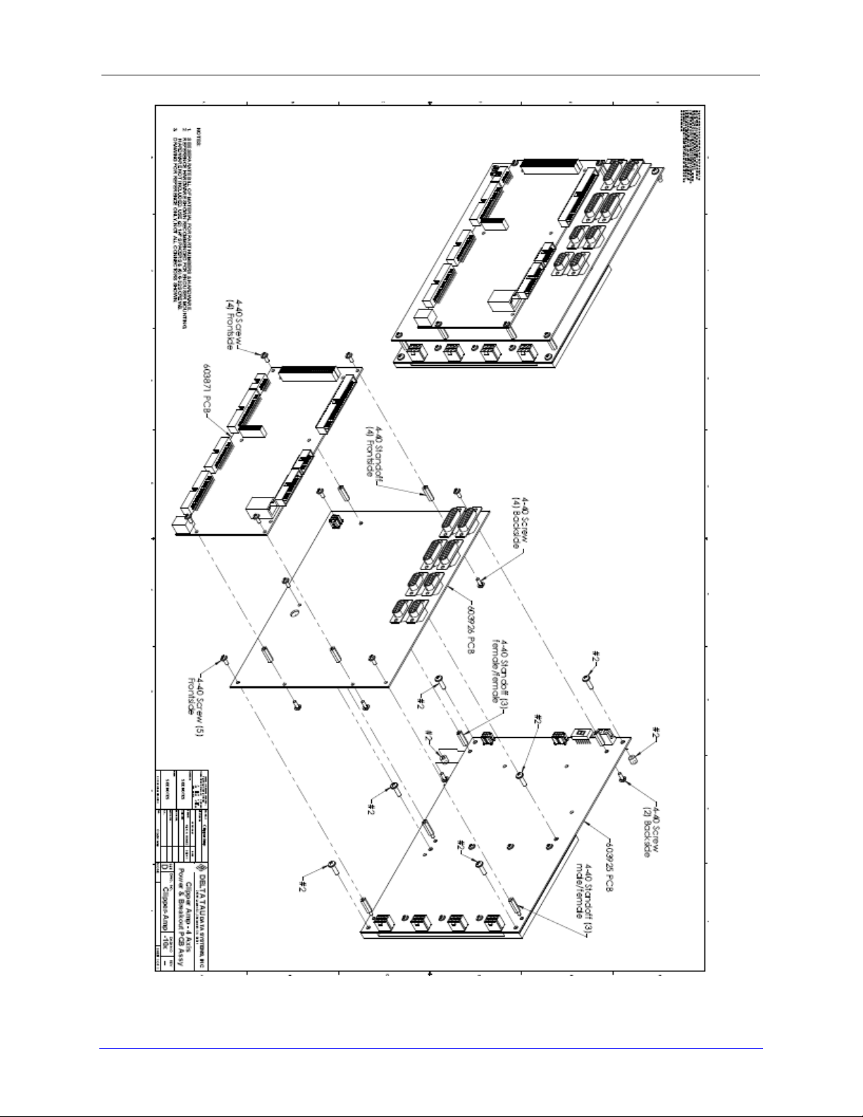
CAD drawing below shows the location of screws for mounting the drive to plate and mounting
the breakout board to the drive.
Receiving and Unpacking 11
Page 12
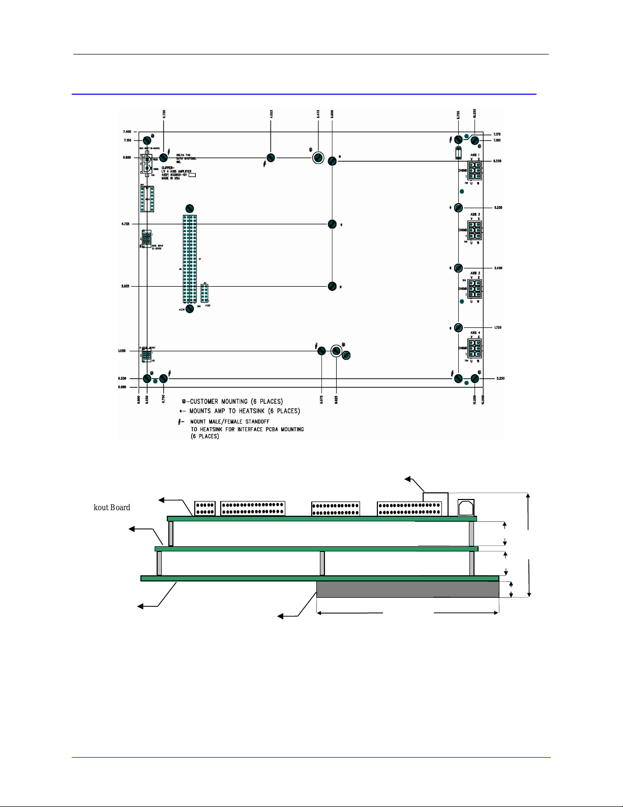
Breakout Board
(603926)
2.25
Power Board
Clipper Board
Ethernet
0.25
5.31
5.125
5.125
Heat Sink
CAD Drawing
Turbo Clipper Drive User Manual
(603871)
(603925)
Receiving and Unpacking 12
Page 13
Turbo Clipper Drive User Manual
Receiving and Unpacking 13
Page 14

Turbo Clipper Drive User Manual
WARNING
Installation of electrical control equipment is subject to
many regulations including national, state, local, and
industry guidelines and rules. General recommendations can
be stated but it is important that the installation be carried
out in accordance with all regulations pertaining to the
installation.
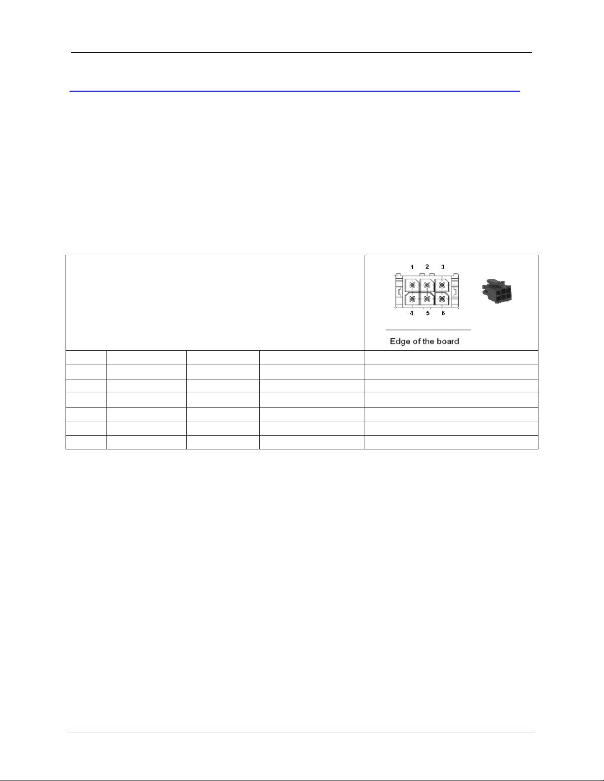
TB1-TB4: Molex (F)
Molex Mating Connector Part #: 39-01-2065 (M)
Molex Crimper Pin Part #: 39-00-0060
For Internal Use:
DT Part #: 014-390120-065
DT Part #: 014-555656-083
Pin #
Symbol
Description
1
U Phase
Axis 1-4
2
GND
Ground
3
V Phase
Axis 1-4
4
W Phase
Axis 1-4 5 GND
Ground
6
X Phase
Axis 1-4
Note
DC Brushless motors: Use U, V and W. Leave X floating
Stepper motors: Use U and W at one coil, V and X at the
other coil.
Brush motors: Use U and W. Leave V and X floating.
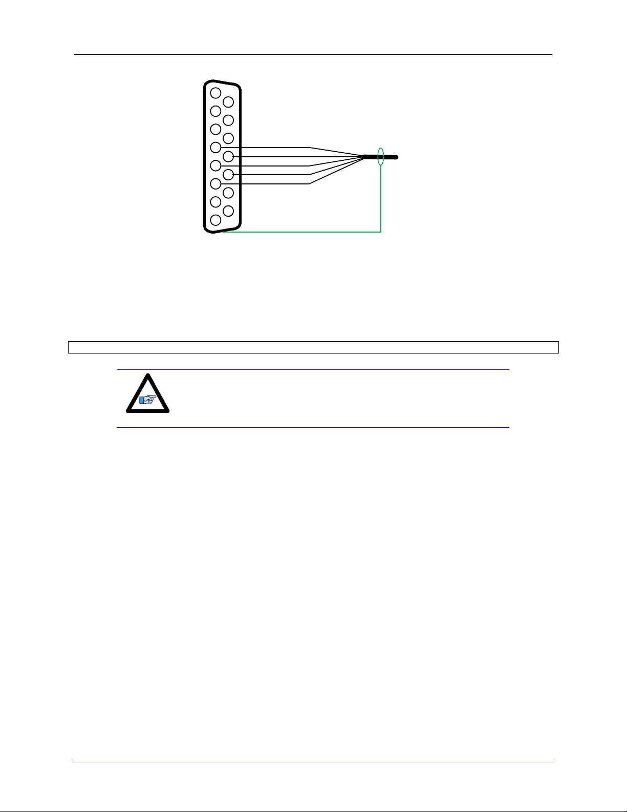
The cable wiring must be shielded and have a separate
conductor connecting the motor frame back to the
assembly ground.
POWER BOARD: WIRING, SOFTWARE SETUP
TB1-TB4: Motor Wiring
Motor phases are conversed in one of three conventions. Some motor manufacturers will call the
motor phases A, B, or C. Other motor manufacturers call them U, V, W. The Turbo Clipper
Drive outputs are called U, V, W, and X. For DC brushless motors (servo) use U,V and W, let X
float. For stepper motors, use U and W for one coil, V and X for the other coil. For DC Brush
motors, use U and W, float V and X. The motor’s frame drain wire and the motor cable shield
must be tied together and wired at the GND pin of the motor connector (Pin 5 or 2).
Power board: Wiring, Software Setup 14
Page 15
Turbo Clipper Drive User Manual
TB5: Molex (F)
Molex Mating Connector Part #: 43025 (M)
Molex Crimper Pin Part #: 43030-0008
For Internal Use:
DT Part #: 014-430250-600
DT Part #: 014-43030-008
Pin #
Symbol
Function
Description
Notes
1
24VDC
Input
Logic power input
+16~32VDC
2
NA
NA
NA
NA
3
24VDC RET
Common
Logic power return
Power Supply Return
4
24VDC
Input
Logic power input
+16~32VDC
5
NA
NA
NA
NA
6
24VDC RET
Common
Logic power return
Power Supply Return
TB5: 24-Volt Logic Power
An external 24Vdc power supply is required to power up the logic portion of the Turbo Clipper
Drive. This power can remain on, regardless of the main DC bus power, allowing the signal
electronics to be active while the main motor power control is inactive. The 24V is wired into
terminal block TB5. The polarity of this connection is extremely important. Carefully follow
the instructions in the wiring diagram. This connection can be made using 22 AWG wire
directly from a protected power supply. In situations where the power supply is shared with
other devices, it may be desirable to insert a filter in this connection.
The 24Volts power supply must be capable of providing 2~3Amps per Turbo Clipper Drive to
allow proper functionality. If multiple drives are sharing the same 24Volts power supply, it is
highly recommended to wire each drive back to the power supply terminals separately.
Power board: Wiring, Software Setup 15
Page 16

TB6: Molex (F)
Molex Mating Connector Part #:: 50-84-1020 (M)
Molex Crimper Pin Part #: 002081001
For Internal Use:
DT Part #: 014-030f02-HSM
DT Part #: 014-002081-001
Pin #
Symbol
Function
Description
Notes
1
+12~60VDC
Input
Bus power input VBus
+12~60VDC
2
+12~60VDC RET
Common
Bus power return 0Bus
+12~60VDC RET
Fuse (FRN/LPN)
Wire Gauge
15
12 AWG
TB6: Bus Voltage
Recommended Fuse, and wire gauge:
Turbo Clipper Drive User Manual
Power board: Wiring, Software Setup 16
Page 17

Turbo Clipper Drive User Manual
TB6: Molex (F)
Molex Mating Connector Part #: 430250-0400 (M)
Molex Crimper Pin Part #: 43030-0008
For Internal Use:
DT Part #: 014-430250-400
DT Part #: 014-43030-008
Pin #
Symbol
Description
1
Reset
Connect 1-2 to activate the reset.
2
Reset
3
E-STOP
Connect 3-4 to engage the E-Stop
4
E-STOP
Note
The built-in Emergency Stop circuitry disables the Mosfet
transistors but does NOT remove power from the DC bus. If this
additional level of protection is required, it is recommended to
add a separate external device to remove the DC Bus input from
the Turbo Clipper Drive.
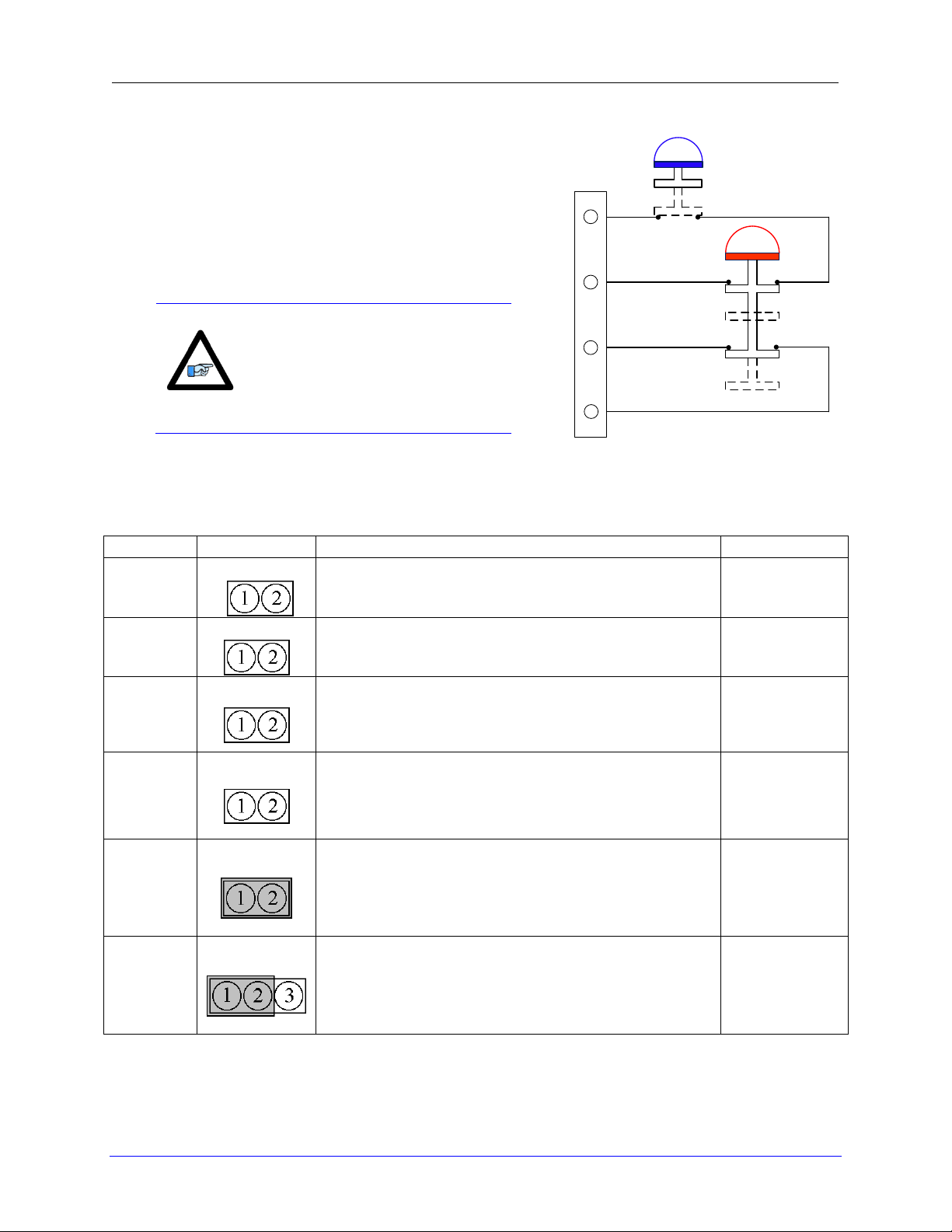
J13: E-Stop, Reset
The Turbo Clipper Drive is equipped with a built-in Emergency Stop circuitry. It utilizes two
latching type relays to enable/disable the drive’s Mosfet transistors. Additionally, the following
safety and status features are implemented:
The E-Stop status, by default, is conveyed to the Turbo Clipper via User Flag Input #4
(X:$78018,19).See jumper J39.
The General Purpose Outputs (GPO), by default, is independent of the E-Stop status.
They can be disabled in an emergency stop condition. See jumper J36.
The Turbo Clipper Drive has an E-Stop software controllable enable bit (Y:$78402,15,1).
It is a low true logic meaning =0 to engage E-Stop, =1 to disengage E-Stop, allowing the
user to trigger an emergency stop condition through software logic.
Power board: Wiring, Software Setup 17
Page 18
Turbo Clipper Drive User Manual
The E-Stop button should be a normally-closed switch, so
that the circuit is closed when it is released and open when
it is pressed.
The Reset button should be a normally-open switch before
revision 103, so that the circuit is open when it is released
and closed when it is pressed. Revision 103 and after the
type of Reset button can be selectable via jumper E4.
Note
It is recommended to wire the EStop in series with the reset
circuit, so if the machine is in an
emergency stop condition, the
reset cannot be activated and has
no practical use.
E-STOP
Normally
Open
Normally
Closed
RESET
1
2
3
4
J13
Board
Jumper
Function
Default
Power
E1
Remove to enable the hard E-Stop function.
Install to disable the hard E-Stop function.
Not Installed
Power
E2
Remove to enable hard & soft E-Stop functions.
Install to disable hard & soft E-Stop functions.
Not Installed
Power
E3
Remove to enable the soft E-Stop function.
Install to disable the soft E-Stop function
(Soft E-Stop bit has to be set, and saved to 1).
Not Installed
Power
E4
Remove jumper to use normally-open Reset switch
between pin 1 and 2 of J13.
Install jumper to use normally-closed Reset switch
between pin 1 and 2 of J13.
Not Installed
Breakout
J36
Install jumper to disable the GPO E-Stop automatic
feature (outputs unaffected by E-Stop status).
Remove Jumper to enable the GPO E-Stop
automatic feature (turn outputs off when in E-Stop)
Installed
Breakout
J39
Jump 1 to 2 to use User Flag 4 as an E-Stop status
in software.
Jump 2 to 3 to use User Flag 4 as a general purpose
user input.
Jumpered
1-2
Wiring The E-Stop, And Reset Switch
Emergency Stop, Reset Jumpers Summary
The following table summarizes the E-Stop and Reset features. The hard E-Stop designates the
actual hardware E-Stop button. The soft E-Stop designates the software controllable E-Stop bit:
Power board: Wiring, Software Setup 18
Page 19

Turbo Clipper Drive User Manual
Note
Upon releasing the E-Stop, the General Purpose Outputs (GPO)
state, otherwise handled by PLC/software, is re-established to
what it was prior to pressing the E-Stop.
Emergency Stop-Reset Example PLC
In addition to the automatic Emergency Stop functionality a PLC must be used to insure proper
and complete Emergency Stop function once the Mosfet transistors are disabled. During an
emergency stop condition, it is highly advised to implement the following:
Kill motors.
Turn off general purpose outputs (GPOs).
Other functions insuring machine safety.
With E1, E2, E3, and E4 removed allowing both hardware and software E-Stop functionality.
J36 removed, to automatically turn off the general purpose outputs, and J39 set to 1-2 to allow
reading the E-Stop status through User flag4:
// Definition and Substitutions
#define Estop_Latch P8000 ; General purpose Latching flag
#define Estop_Enable M47 ; Software Controllable E-Stop Bit
Estop_Enable->Y:$78402,15,1 ; =0 E-Stop, =1 Not in E-Stop
Estop_Enable=1
#define Estop_Status M415 ; S-Stop Status Bit, using User Flag 4
Estop_Status->X:$78018,19 ; =1 E-Stop, =0 Not in E-Stop
Open PLC 1 Clear
// Is E-Stop Pressed?
If (Estop_Status=1)
Estop_Latch=0
Else
Estop_Latch=1
EndIF
Estop_Enable=1 ; Set once on power-up
While (1=1)
// Emergency Stop Engaged
If(Estop_Status = 1 and Estop_Latch = 0)
// Put Emergency Stop Functions Here
&1 CMD^K ; Kill all axes in Coordinate System 1
// Set desired Outputs state (post E-Stop) here
// if automatic GPO kill is enabled
Estop_Latch = 1
Else
// Emergency Stop Released
IF(Estop_Status = 0 and Estop_Latch = 1)
// Put Emergency Stop Release Functions Here
&1 CMD^A ; Enable all axes in Coordinate System 1
Estop_Latch = 0
P8002=P8002+1
EndIf
EndIf
Endwhile
Close
Power board: Wiring, Software Setup 19
Page 20

Turbo Clipper Drive User Manual
Display
Description
Global Faults
Under Voltage Fault:
Indicates that the bus voltage is not present or less than 12Volts
Over Voltage Fault:
Indicates that the bus voltage has exceeded 60Volts
Over Temperature Fault:
Indicates that the Board has exceeded 65°C
Axis n Faults (n=1 thru 4)
n
Axis n Over load Fault:
Indicates that the current rating (5/15A) of the drive has been exceeded
n
Axis n Over Current Fault:
Indicates that the peak current value has exceeded the permissible limit(20Amps)
D1: AMP STATUS
The Turbo Clipper Drive utilizes a scrolling single-digit 7-segment display to exhibit faults to the
outside world. When control and DC bus power are applied, the Drive will display a solid dot
indicating that the software and hardware are running normally.
Error Codes
Power board: Wiring, Software Setup 20
Page 21
Turbo Clipper Drive User Manual
Caution
This connector is only used if the power board is not present. It
is utilized to bring in logic power to the control (Clipper) and
breakout boards.
TB1: Molex (F)
Molex Mating Connector Part #:: 39-01-2045 (M)
Molex Crimper Pin Part #: 39-00-0060
For Internal Use:
DT Part #: 014-390120-045
DT Part #: 014-555656-083
Pin #
Symbol
Function
Notes
1
GRD
Input
Ground
2
+5 VDC
Input
5 volt Input
3
+12 VDC
Input
12 volt Input
4
-12 VDC
Input
-12 volt Input
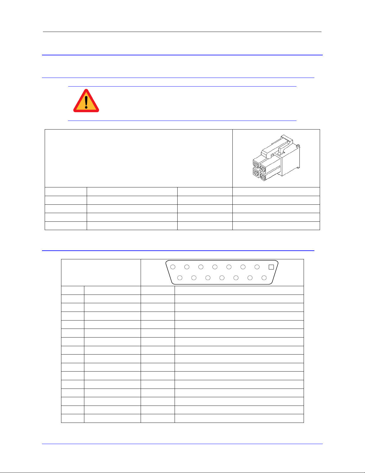
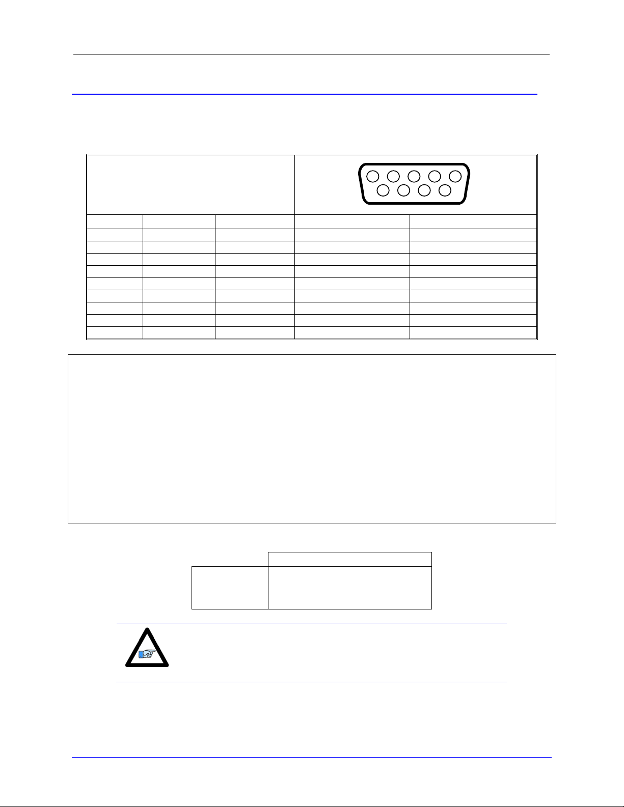
J11-J14: D-sub DA-15F
Mating: D-sub DA-15M
2345
9101112
67
1314
8
15
1
Pin#
Symbol
Function
Description
1
CHA+
Input
Axis Encoder A+
2
CHB+
Input
Axis Encoder B+
3
CHC+
Input
Axis Encoder Index+
4
ENCPWR
Output
Encoder Power 5V
5
CHU+ / DIR+
In/Out
Halls U+ / Direction Output + for Stepper
6
CHW+/ PUL+
In/Out
Halls W+ / Pulse Output + for Stepper
7
2.5V
Output
2.5V Reference power
8
Stepper Enable
Input
Tie to pin#4 (5V) to enable stepper output
9
CHA-
Input
Axis Encoder A-
10
CHB-
Input
Axis Encoder B-
11
CHC-
Input
Axis Encoder Index-
12
GND
Common
Common ground
13
CHV+ / DIR-
In/Out
Halls V+ / Direction Output- for Stepper
14
CHT+ / PUL-
In/Out
Halls T+ / Pulse Output- for Stepper
15
N/C
-
Reserved for future use
BREAKOUT BOARD: WIRING, SOFTWARE SETUP
TB1: External Power Supply
J11-J14: Encoder Feedback, Digital A Quad B
Breakout Board: Wiring, Software Setup 21
Page 22
Turbo Clipper Drive User Manual
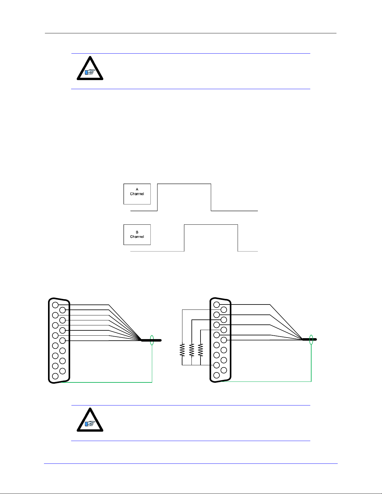
Note
Spacing specs between DB-Connectors can be found in
Appendix section.
12345678
9101112131415
CHA+
CHACHB+
CHBCHC+
CHC+5VDC
GND
12345678
9101112131415
CHA+
CHB+
CHC+
+5VDC
GND
1.2KΩ
1.2KΩ
1.2KΩ
Differential Quadrature Encoder Wiring
Single-Ended Quadrature Encoder Wiring
Note
For single-ended encoders, tie the negative pins (i.e. CHAn-) to
reference (Pin#7) in series with a 1Kohm resistor.
The standard encoder input channels on the Turbo Clipper Drive Drive are designed for
differential quadrature feedback. To use single-ended encoders, the negative pins (i.e. CHAn-)
have to be tied to reference (Pin#7) in series with a 1Kohm resistor.
Quadrature encoders provide two digital signals to determine the position of the encoder/motor.
Each nominally with 50% duty cycle, and nominally 1/4 cycle apart. This format provides four
distinct states per cycle of the signal, or per line of the encoder. The phase difference of the two
signals permits the decoding electronics to discern the direction of travel, which would not be
possible with a single signal.
Typically, these signals are 5V TTL/CMOS level, whether they are single-ended or differential.
Differential encoder signals can enhance noise immunity by providing common mode noise
rejection. Modern design standards virtually mandate their use in industrial systems.
Breakout Board: Wiring, Software Setup 22
Page 23
Turbo Clipper Drive User Manual
12345678
9101112131415
+5VDC
GND
CHU+
CHV+
CHW+
Note
At this point of the setup, you should be able to move the
motor/encoder shaft by hand and see ‘motor’ counts in the
position window
Hall-Effect Sensor Wiring
Motor Activation: Ixx00
Digital Quadrature Encoders use the 1/T incremental entry in the encoder conversion table.
Position and Velocity pointers are by default valid and in most cases no special software setup is
required, activating the motor(s) is sufficient to see encoder counts in the position window when
the motor/encoder shaft is moved by hand.
I100,4,100=1 ; Motors 1-4 activated
Breakout Board: Wiring, Software Setup 23
Page 24
Turbo Clipper Drive User Manual
J9-J12: D-Sub DE-9F
Mating: D-Sub DE-9M
12345
6789
Pin #
Symbol
Function
Description
Notes
1
SIN +
Analog Input
Sinusoidal input+
2 COS +
Analog Input
Cosine input+
3 INDEX +
Input
Index input
Analog or TTL levels
4
ENCPWR
Output
Encoder power
+5VDC
5
GND
Digital ground
6
SIN -
Analog Input
Sinusoidal input-
7 COS -
Analog Input
Cosine input-
8 INDEX -
Input
Index input
Analog or TTL levels
9
VREF
2.5V Output
A-D reference output
Position And Velocity Pointers
Channels 1-4
I103=$3503 I104=$3503
I203=$3506 I204=$3506
I303=$3509 I304=$3509
I403=$350C I404=$350C
Note
At this point of the setup, you should be able to move the
motor/encoder shaft by hand and see ‘motor’ counts in the
position window
ACC-51S: Sinusoidal Feedback (Optional)
The accessory ACC-51S allows the Turbo Clipper Drive to interface to up to 4 sinusoidal
feedback devices. This high resolution interpolator circuitry accepts inputs from sinusoidal or
quasi-sinusoidal encoders (1-Volt peak to peak) and provides encoder position data. It creates
4,096 steps per sine-wave.
// Channel 1
I8000=$FF8000 ; High resolution interpolator
I8001=$078B00 ; A/D converter address
I8002=$000000 ; Bias Term and Entry result
// Channel 2
I8003=$FF8008 ; High resolution interpolator
I8004=$078B02 ; A/D converter address
I8005=$000000 ; Bias Term and Entry result
// Channel 3
I8006=$FF8010 ; High resolution interpolator
I8007=$078B04 ; A/D converter address
I8008=$000000 ; Bias Term and Entry result
// Channel 4
I8009=$FF8018 ; High resolution interpolator
I8010=$078B06 ; A/D converter address
I8011=$000000 ; Bias Term and Entry result
I100,4,100=1 ; Axis 1-4 active
Position and Velocity feedback pointers should now be set to the corresponding ECT result:
Breakout Board: Wiring, Software Setup 24
Page 25
Turbo Clipper Drive User Manual
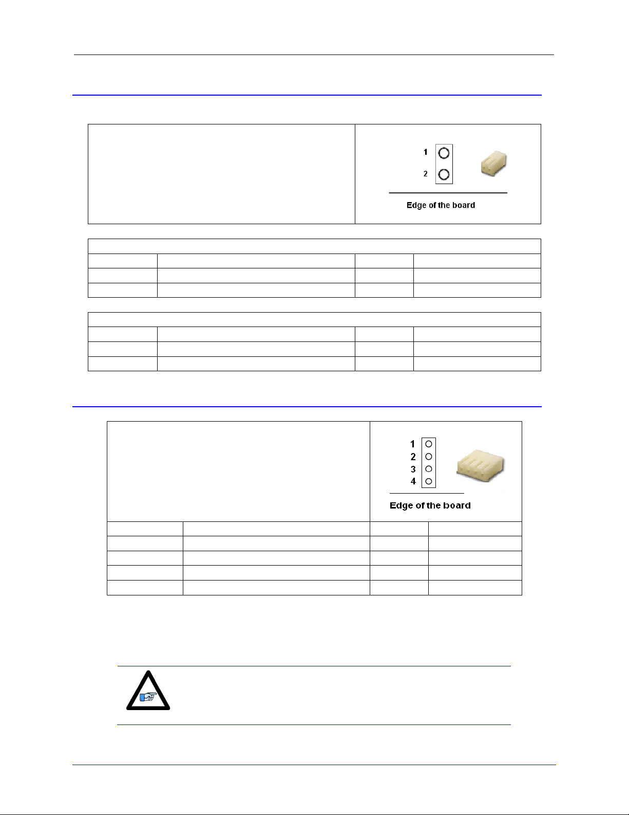
J15: Molex (M)
Molex Mating Connector Part #:: 22-01-3027 (F)
Molex Crimper Pin Part #: 08-50-0114
For Internal Use:
DT Part #: 014-000R02-LHM
DT Part #: 025-500114-PNM
Sinking Configuration
Pin #
Symbol
Function
Description
1
24VDC FLA_PWR
Input
Flag Power (+24VDC)
2
24VDC FLA_RET
Input
Flag Return (Common)
Sourcing Configuration
Pin #
Symbol
Function
Description
1
24VDC FLA_RET
Input
Flag Return (Common)
2
24VDC FLA_PWR
Input
Flag Power (+24VDC)
J16/J17/J18/J19: Molex (M)
Molex Mating Connector Part #: 22-01-3047 (F)
Molex Crimper Pin Part #: 08-50-0114
For Internal Use:
DT Part #: 014-000R04-LHM
DT Part #: 025-500114-PNM
Pin #
Symbol
Function
Description
1
PLIM +
Input
Positive Limit+
2
MLIM +
Input
Negative Limit+ 3 HOME +
Input
Home+
4
FLA_PWR/RET
Common
Flag PWR/RET
Note
For 5V flags: Install RP3, RP7, RP11, RP15 (1 kΩ sip).
SIPs are 8-pin, four independent Resistors.
For 12-24V flags: Empty bank (default).
J15: Flag(s) Power Supply
The flag(s) wiring is user configurable; it can be either sinking or sourcing.
J16-J19: Axis 1 thru 4 Limits & Home Flags
The Turbo Clipper Drive limits and flags circuitry offers a flexible 12-24Volts or 5Volts
connectivity. In its default configuration, the flags and limits are 12-24Volts inputs. If you are
using 5Volt flags and limits, make sure you have ordered the appropriate option before wiring
any flags.
Breakout Board: Wiring, Software Setup 25
Page 26
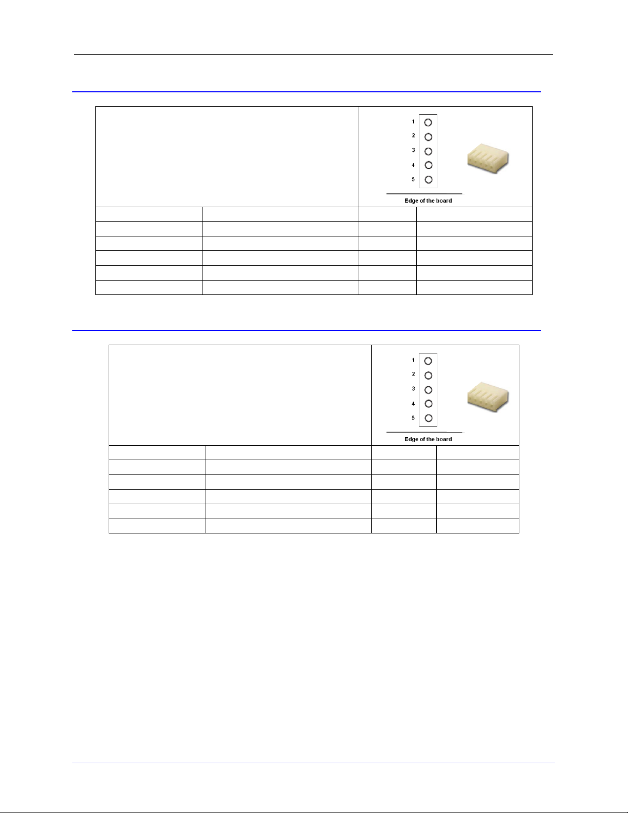
J20: Molex (M)
Molex Mating Connector Part #: 22-01-3057 (F)
Molex Crimper Pin Part #: 08-50-0114
For Internal Use:
DT Part #: 014-000R05-LHM
DT Part #: 025-500114-PNM
Pin #
Symbol
Function
Description
1
EQU_1+
Input
Position Compare 1+
2
EQU_2+
Input
Position Compare 2+
3
EQU_3+
Input
Position Compare 3+
4
EQU_4+
Input
Position Compare 4+
5
GND
Common
Ground
J21: Molex (M)
Molex Mating Connector Part #: 22-01-3057 (F)
Molex Crimper Pin Part #: 08-50-0114
For Internal Use:
DT Part #: 014-000R05-LHM
DT Part #: 025-500114-PNM
Pin #
Symbol
Function
Description
1
USER_1+
Input
User Flag 1+
2
USER_2+
Input
User Flag 2+
3
USER _3+
Input
User Flag 3+
4
USER _4+
Input
User Flag 4+ 5 GND
Common
Ground
J20: Axis 1 thru 4 EQU Outputs
J21: Axis 1 thru 4 User Flags
Turbo Clipper Drive User Manual
Breakout Board: Wiring, Software Setup 26
Page 27
Turbo Clipper Drive User Manual
J15:Power Supply Input
Sinking/Sourcing
Pin#1
Pin#2
Sinking
24VDC+
+24VDC RET
Sourcing
+24VDC RET
24VDC+
Flag Supply
12-24VDC
24V
Return
Flag
Sourcing
Separate
Supply
0V
Flag Supply
12-24VDC
24V
0V
Return
Flag
Sinking
Separate
Supply
Limits and Flags (Axis1- 4) Suggested M-Variables
M115->X:$078000,19 ; User 1 flag input status
M116->X:$078000,9 ; EQU1, ENC1 compare output value
M120->X:$078000,16 ; Home flag 1 input status
M121->X:$078000,17 ; Positive Limit 1 flag input status
M122->X:$078000,18 ; Negative Limit 1 flag input status
M215->X:$078008,19 ; User 2 flag input status
M216->X:$078008,9 ; EQU2, ENC2 compare output value
M220->X:$078008,16 ; Home flag 2 input status
M221->X:$078008,17 ; Positive Limit 2 flag input status
M222->X:$078008,18 ; Negative Limit 2 flag input status
M315->X:$078010,19 ; User 3 flag input status
M316->X:$078010,9 ; EQU3, ENC3 compare output value
M320->X:$078010,16 ; Home flag 3 input status
M321->X:$078010,17 ; Positive Limit 3 flag input status
M322->X:$078010,18 ; Negative Limit 3 flag input status
M415->X:$078018,19 ; User 4 flag input status
M416->X:$078018,9 ; EQU4, ENC4 compare output value
M420->X:$078018,16 ; Home flag 4 input status
M421->X:$078018,17 ; Positive Limit 4 flag input status
M422->X:$078018,18 ; Negative Limit 4 flag input status
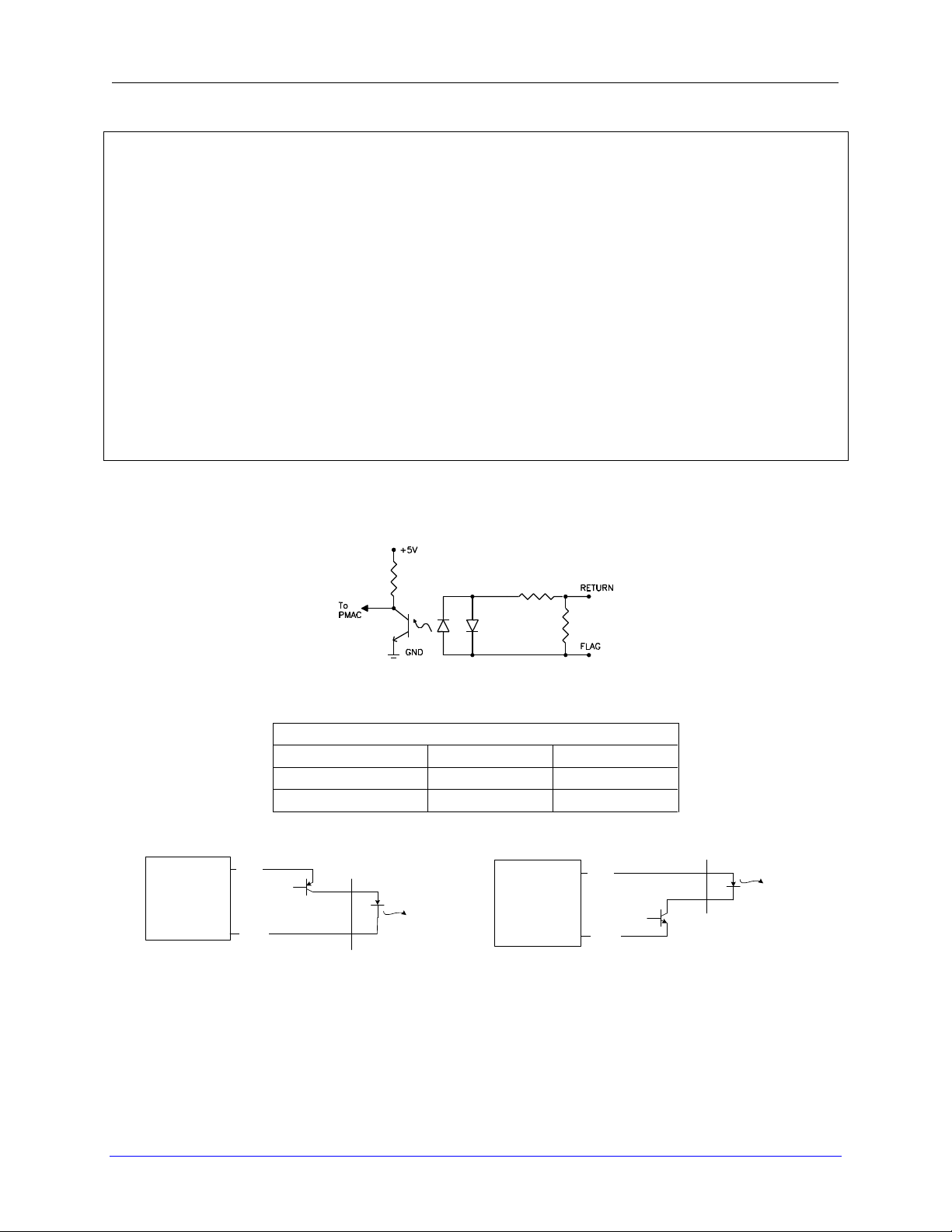
The Turbo Clipper Drive allows the use of sinking or sourcing limits and flags. The opto-isolator
IC used is a PS2705-1NEC quad phototransistor output type. This IC allows the current to flow
from return to flag (sinking) or from flag to return (sourcing).
The flags can be sinking and/or sourcing per channel depending on the Flag Input Power Supply
J15 wiring.
Breakout Board: Wiring, Software Setup 27
Page 28

1
2
3
4
Sinking
0V
24V
1
2
24 V Supply
J15
Breakout
Outside
FL_RT
FLA_PWR/RET
FLA_RET/PWR
Load
Load
Load
Pos.Limit
Neg.Limit
Home
1
2
3 4 5
User 1
User 2
User 3
User 4
1
2
3 4 5
EQU 1
EQU 2
EQU 3
EQU 4
1
2
3
4
J16-J19
0V
24V
1
2
24 V Supply
J15
Breakout
Outside
FL_RT
FLA_PWR/RET
FLA_RET/PWR
Load
Load
Load
Pos.Limit #n
Neg.Limit #n
Sourcing
0V
12~24V
24V
User Flags and EQU Outputs
J16-J19
J21
J20
Wiring The Flags
Turbo Clipper Drive User Manual
World
Flags
Board
World
Board
Flags
Supply
Breakout Board: Wiring, Software Setup 28
Page 29

Turbo Clipper Drive User Manual
J21: Molex (M)
Molex Mating Connector Part #: 22-01-3027 (F)
Molex Crimper Pin Part #: 08-50-0114
For Internal Use:
DT Part #: 014-000R02-LHM
DT Part #: 025-500114-PNM
Pin #
Symbol
Function
Description
1
+5V_5A
Output
5 volts in normal operation
2
B_WDO
Output
Ground
J23: Watchdog Output
This connector allows the user to send Ohm output from the Turbo Clipper Drive to the machine
if a watchdog condition has occurred. This is an important safety feature because the Clipper
Amp is totally disabled when it is in watchdog condition and this output will allow the other
machine’s hardware/logic to bring the process to a safe condition. In normal operation there is 5
volts between pin 1 and 2 and in the time of watchdog this will drop to zero.
Breakout Board: Wiring, Software Setup 29
Page 30

Turbo Clipper Drive User Manual
Note
This feature is only available if the power board is not present.
J24: Molex (M)
Molex Mating Connector Part #: 22-01-3037 (F)
Molex Crimper Pin Part #: 08-50-0114
For Internal Use:
DT Part #: 014-000R03-LHM
DT Part #: 025-500114-PNM
Pin #
Symbol
Function
Description
1
GRD
Output
Ground
2
DAC_PWM+
Output
DAC Output+
3
DAC_PWM-
Output
DAC Output-
M8000
DAC (V)
0
0
981
10
J24: DAC Output, 12-bit Filtered PWM
The Turbo Clipper board, ordered with Option-12, has an additional 12-bit filtered PWM output.
I6800= 981 ; PWM frequency ~30kHz
I6801= 5 ; Phase Clock ~10kHz
I6802= 3 ; Servo frequency ~2.5Hz
I6816= 0 ; Output Model PWM
I569= 981 ; DAC limit 10Vdc
I502 =$07841A ; Only Second output is used
M8000->Y:$7841A,8,16,S ; Supplementary Channel 2* Output A Command Value
; Min=0, Max= Ixx69
Testing The Filtered PWM DAC Output
Writing, directly to the suggested M-variable (i.e. M8000), produces corresponding voltages:
Breakout Board: Wiring, Software Setup 30
Page 31

Turbo Clipper Drive User Manual
Note
This feature is only available if the power board is not present.
J25: Molex (M)
Molex Mating Connector Part #: 22-01-3037 (F)
Molex Crimper Pin Part #: 08-50-0114
For Internal Use:
DT Part #: 014-000R03-LHM
DT Part #: 025-500114-PNM
Pin #
Symbol
Function
Description
1
GRD
Input
Ground
2
ADC_IN 1
Input
ADC Input 1
3
ADC_IN 2
Input
ADC Input 2
Input Voltage
Software Counts
Bipolar
-10
-2048
-5
-1024
+10
+2048
+5
+1024
Input Voltage
Software Counts
Unipolar
+10
+2048
+5
+1024
Note
These ADCs do not provide full resolution in Unipolar (0-10V,
or 0-5V) mode. Only Bipolar inputs are supported for the full
12-bit (4096 count range) resolution.
J25: ADC Inputs
The Turbo Clipper board, ordered with Option-12, provides with two single ended 12-bit analog
inputs. The ±10V input range corresponds to ±2048 software counts.
Setting Up The Analog Inputs:
Bipolar Mode
I7003 = 1746 ; Set ADC clock frequency at 4.9152 MHz
I7006 = $1FFFFF ; ADC Strobe Word
M105->Y:$78005,12,12,S ; ADC Input 1 on J25 pin 2
M205->Y:$7800D,12,12,S ; ADC Input 2 on J25 pin 3
Unipolar Mode
I7003 = 1746 ; Set ADC clock frequency at 4.9152 MHz
I7006 = $1FFFFF ; ADC Strobe Word
M105->Y:$78005,12,12,u ; ADC Input 1 on J25 pin 2
M205->Y:$7800D,12,12,u ; ADC Input 2 on J25 pin 3
Testing the Analog Inputs:
Breakout Board: Wiring, Software Setup 31
Page 32

J26: Molex (M)
Molex Mating Connector p/n#:22-01-3107 (F)
Molex Crimper Pin Part #: 08-50-0114
For Internal Use:
DT Part #: : 014-000W10-LHM
DT Part #: 025-500114-PNM
Pin#
Symbol
Function
Description
1
IN_PWR/RET
RTNFL
Return Flag (Tie to 0V or 24V)
2
IN_COM_1
RTNFL
Return Flag (Tie to 0V or 24V)
3
JTHW_IN00
Input
DAT0
4
JTHW_IN01
Input
DAT1
5
JTHW_IN02
Input
DAT2
6
JTHW_IN03
Input
DAT3
7
JTHW_IN04
Input
DAT4
8
JTHW_IN05
Input
DAT5
9
JTHW_IN06
Input
DAT6
10
JTHW_IN07
Input
DAT7
J26: Thumbwheel Multiplexer Port Inputs
Turbo Clipper Drive User Manual
Breakout Board: Wiring, Software Setup 32
Page 33

Turbo Clipper Drive User Manual
J27: Molex (M)
Molex Mating Connector Part #: 22-01-3107 (F)
Molex Crimper Pin Part #: 08-50-0114
For Internal Use:
DT Part #: : 014-000W10-LHM
DT Part #: 025-500114-PNM
Pin #
Symbol
Function
Description
1
COM_EMT _1
RTNFL
Tie to Common 0V (Sinking)
2
COM_EMT_1
RTNFL
Tie to Common 0V (Sinking)
3
JTHW_OUT1+
Input
SEL 0
4
JTHW_OUT2+
Input
SEL 1
5
JTHW_OUT3+
Input
SEL 2
6
JTHW_OUT4+
Input
SEL 3
7
JTHW_OUT5+
Input
SEL 4 8 JTHW_OUT6+
Input
SEL 5
9
JTHW_OUT7+
Input
SEL 6
10
N/A
N/A
N/A
J27: Thumbwheel Multiplexer port Outputs (sinking)
Breakout Board: Wiring, Software Setup 33
Page 34

Turbo Clipper Drive User Manual
J37: Molex (M)
Molex Mating Connector Part #: 22-01-3107 (F)
Molex Crimper Pin Part #: 08-50-0114
For Internal Use:
DT Part #: 014-000W10-LHM
DT Part #: 025-500114-PNM
Pin #
Symbol
Function
Description
1
COM_COL_1
RTNFL
Tie to 24VDC (Sourcing)
2
COM_COL_1
RTNFL
Tie to 24VDC (Sourcing)
3
JTHW_OUT1-
Output
SEL0 4 JTHW_OUT2-
Output
SEL 1
5
JTHW_OUT3-
Output
SEL 2
6
JTHW_OUT4-
Output
SEL 3
7
JTHW_OUT5-
Output
SEL 4
8
JTHW_OUT6-
Output
SEL 5
9
JTHW_OUT7-
Output
SEL 6
10
N/A
N/A
N/A
J37: Thumbwheel Multiplexer port Outputs (Sourcing)
Thumbwheel Port As Discrete I/Os, Suggested M-Variables
The inputs and outputs on the thumbwheel multiplexer port (J26-J27-J37) can be used as
discrete, non-multiplexed general purpose I/Os, and accessed through M-Variable pointers:
M40->Y:$78402,8,1 ; SEL0 Output
M41->Y:$78402,9,1 ; SEL1 Output
M42->Y:$78402,10,1 ; SEL2 Output
M43->Y:$78402,11,1 ; SEL3 Output
M44->Y:$78402,12,1 ; SEL4 Output
M45->Y:$78402,13,1 ; SEL5 Output
M46->Y:$78402,14,1 ; SEL6 Output
M47->Y:$78402,15,1 ; SEL7 Output
M48->Y:$78402,8,8,U ; SEL0-7 Outputs treated as a byte
M50->Y:$78402,0,1 ; DAT0 Input
M51->Y:$78402,1,1 ; DAT1 Input
M52->Y:$78402,2,1 ; DAT2 Input
M53->Y:$78402,3,1 ; DAT3 Input
M54->Y:$78402,4,1 ; DAT4 Input
M55->Y:$78402,5,1 ; DAT5 Input
M56->Y:$78402,6,1 ; DAT6 Input
M57->Y:$78402,7,1 ; DAT7 Input
M58->Y:$78402,0,8,U ; DAT0-7 Inputs treated as a byte
Breakout Board: Wiring, Software Setup 34
Page 35

1
2
3
4
5
6 7 8
9
10
J26
Sinking
0V
24V
1
2
24 V Supply
Inputs
1-8
J30
Breakout
Outside
JTHW_IN01
PWR
COM
JTHW_IN02
JTHW_IN03
JTHW_IN04
JTHW_IN05
JTHW_IN06
JTHW_IN07
JTHW_IN08
1
2
3
4
5
6 7 8
9
10
J26
Sourcing
1
2
Inputs
1-8
J30
Breakout
Outside
JTHW_IN01
GRD
COM
JTHW_IN02
JTHW_IN03
JTHW_IN04
JTHW_IN05
JTHW_IN06
JTHW_IN07
JTHW_IN08
0V
24 V Supply
24V
PWR/RET
RET/PWR
RET/PWR
PWR/RET
Wiring The Thumbwheel As Discrete I/Os
Turbo Clipper Drive User Manual
World
Board
World
Board
Input
Input
Breakout Board: Wiring, Software Setup 35
Page 36

Turbo Clipper Drive User Manual
Sinking
1
2
3 4 5
6
7
8
9
10
J37
24V
0V
24 V Supply
Breakout
Outside
JTHW_OUT01-
COM_COL _1
COM_COL_1
JTHW_OUT02-
JTHW_OUT03-
JTHW_OUT04-
JTHW_OUT05-
JTHW_OUT06-
JTHW_OUT07-
JTHW_OUT08Output 01
Output 02
Output 03
Output 04
Output 05
Output 06
Output 07
Output 08
1
2
3
4
5
6
7
8
9
10
J27
Sourcing
24V
0V
24 V Supply
Breakout
Outside
JTHW_OUT01+
COM_EMT_1
COM_EMT_1
JTHW_OUT02+
JTHW_OUT03+
JTHW_OUT04+
JTHW_OUT05+
JTHW_OUT06+
JTHW_OUT07+
JTHW_OUT08+
Output 01
Output 02
Output 03
Output 04
Output 05
Output 06
Output 07
Output 08
World
Board
World
Board
Output
Output
Breakout Board: Wiring, Software Setup 36
Page 37

J28: Molex (M)
Molex Mating Connector pn#: 22-01-3107(F)
Molex Crimper Pin Part #: 08-50-0114
For Internal Use:
DT Part #: 014-000W10-LHM
DT Part #: 025-500114-PNM
Pin #
Symbol
Function
Description
1
IN_PWR/RET
RTNFL
Return Flag (Tie to 0V or 24V)
2
IN_COM_2
RTNFL
Return Flag (Tie to 0V or 24V)
3
JOPT_IN01
Input
Input 1
4
JOPT_IN02
Input
Input 2
5
JOPT_IN03
Input
Input 3
6
JOPT_IN04
Input
Input 4
7
JOPT_IN05
Input
Input 5
8
JOPT_IN06
Input
Input 6
9
JOPT_IN07
Input
Input 7
10
JOPT_IN08
Input
Input 8
J28: General Purpose Inputs
Turbo Clipper Drive User Manual
Breakout Board: Wiring, Software Setup 37
Page 38

J29: Molex (M)
Molex Mating Connector pn#: 22-01-3107 (F)
Molex Crimper Pin Part #: 08-50-0114
For Internal Use:
DT Part #: 014-000W10-LHM
DT Part #: 025-500114-PNM
Pin #
Symbol
Function
Description
1
COM_EMT_2
RTNFL
Tie to Common 0V (Sinking)
2
COM_EMT_2
RTNFL
Tie to Common 0V (Sinking)
3
JOPT_OUT1+
Output
Output 1 + 4 JOPT_OUT2+
Output
Output 2 +
5
JOPT_OUT3+
Output
Output 3 +
6
JOPT_OUT4+
Output
Output 4 +
7
JOPT_OUT5+
Output
Output 5 +
8
JOPT_OUT6+
Output
Output 6 +
9
JOPT_OUT7+
Output
Output 7 +
10
JOPT_OUT8+
Output
Output 8 +
J29: General Purpose Outputs (sinking)
Turbo Clipper Drive User Manual
Breakout Board: Wiring, Software Setup 38
Page 39

Turbo Clipper Drive User Manual
J30: Molex (M)
Molex Mating Connector Part #:: 22-01-3027 (F)
Molex Crimper Pin Part #: 08-50-0114
For Internal Use:
DT Part #: 014-000R02-LHM
DT Part #: 025-500114-PNM
Sinking Configuration
Pin #
Symbol
Function
Description
1
12~24VDC IN_PWR
Input
Flag Power (+24VDC)
2
12~24VDC IN_RET
Input
Flag Return (Common)
Sourcing Configuration
Pin #
Symbol
Function
Description
1
12~24VDC IN_RET
Input
Flag Return (Common)
2
12~24VDC IN_PWR
Input
Flag Power (+24VDC)
J30: General Purpose I/O Power
The general purpose I/O(s) wiring is user configurable; it can be either sinking or sourcing.
Breakout Board: Wiring, Software Setup 39
Page 40

J38: Molex (M)
Molex Mating Connector pn#: 22-01-3107(F)
Molex Crimper Pin Part #: 08-50-0114
For Internal Use:
DT Part #: 014-000W10-LHM
DT Part #: 025-500114-PNM
Pin#
Symbol
Function
Description
1
COM_COL_2
RTNFL
Tie to 24VDC (Sourcing)
2
COM_COL _2
RTNFL
Tie to 24VDC (Sourcing)
3
JOPT_OUT1-
Output
Output 1 - 4 JOPT_OUT2-
Output
Output 2 -
5
JOPT_OUT3-
Output
Output 3 -
6
JOPT_OUT4-
Output
Output 4 -
7
JOPT_OUT5-
Output
Output 5 -
8
JOPT_OUT6-
Output
Output 6 -
9
JOPT_OUT7-
Output
Output 7 -
10
JOPT_OUT8-
Output
Output 8 -
J38: General Purpose Outputs (sourcing)
Turbo Clipper Drive User Manual
Breakout Board: Wiring, Software Setup 40
Page 41

1
2
3 4 5
6
7
8
9
10
J28
Sinking
0V
24V
1
2
12~24 V
Inputs
1-8
J30
Breakout
Outside
JOPT_IN01
PWR
COM
JOPT_IN02
JOPT_IN03
JOPT_IN04
JOPT_IN05
JOPT_IN06
JOPT_IN07
JOPT_IN08
1
2
3
4
5
6 7 8
9
10
J28
Sourcing
1
2
Inputs
1-8
J30
Breakout
Outside
JOPT_IN01
GRD
COM
JOPT_IN02
JOPT_IN03
JOPT_IN04
JOPT_IN05
JOPT_IN06
JOPT_IN07
JOPT_IN08
0V
12~24 V
24V
PWR/RET
RET/PWR
RET/PWR
PWR/RET
Wiring the General Purpose I/Os
Turbo Clipper Drive User Manual
World
Supply
Board
World
Supply
Board
Input
Input
Breakout Board: Wiring, Software Setup 41
Page 42

Turbo Clipper Drive User Manual
Sinking
1
2
3 4 5
6
7
8
9
10
J29
0V
24V
12~24 V
Breakout
Outside
JOPT_OUT01+
COM_EMT_2
COM_EMT_2
JOPT_OUT02+
JOPT_OUT03+
JOPT_OUT04+
JOPT_OUT05+
JOPT_OUT06+
JOPT_OUT07+
JOPT_OUT08+
Output 01
Output 02
Output 03
Output 04
Output 05
Output 06
Output 07
Output 08
1
2
3
4
5
6
7
8
9
10
J38
Sourcing
0V
24V
12~24 V
Breakout
Outside
JOPT_OUT01-
COM_COL_2
COM_COL_2
JOPT_OUT02-
JOPT_OUT03-
JOPT_OUT04-
JOPT_OUT05-
JOPT_OUT06-
JOPT_OUT07-
JOPT_OUT08Output 01
Output 02
Output 03
Output 04
Output 05
Output 06
Output 07
Output 08
World
Supply
Board
World
Supply
Board
Output
Output
Breakout Board: Wiring, Software Setup 42
Page 43

Turbo Clipper Drive User Manual
General Purpose I/Os, Suggested M-Variables
M1->Y:$78400,0 ; Digital Output 1
M2->Y:$78400,1 ; Digital Output 2
M3->Y:$78400,2 ; Digital Output 3
M4->Y:$78400,3 ; Digital Output 4
M5->Y:$78400,4 ; Digital Output 5
M6->Y:$78400,5 ; Digital Output 6
M7->Y:$78400,6 ; Digital Output 7
M8->Y:$78400,7 ; Digital Output 8
M9->Y:$78400,8 ; Digital Input 1
M10->Y:$78400,9 ; Digital Input 2
M11->Y:$78400,10 ; Digital Input 3
M12->Y:$78400,11 ; Digital Input 4
M13->Y:$78400,12 ; Digital Input 5
M14->Y:$78400,13 ; Digital Input 6
M15->Y:$78400,14 ; Digital Input 7
M16->Y:$78400,15 ; Digital Input 8
M32->X:$78400,0,8 ; Direction Control bits 0-7 (1=output, 0 = input)
M34->X:$78400,8,8 ; Direction Control bits 8-15 (1=output, 0 = input)
M40->X:$78404,0,24 ; Inversion control (0 = 0V, 1 = 5V)
M42->Y:$78404,0,24 ; J9 port data type control (1 = I/O)
//In order to properly setup the digital I/Os, an initialization PLC must be written scanning
//through once on power-up/reset, setting control statuses then disabling itself:
Open PLC 1 clear
M32=$FF ; BITS 0-7 are assigned as output
M34=$0 ; BITS 8-15 are assigned as input
M40=$FF00 ; Define inputs and outputs
M42=$FFFF ; All lines are I/O type
DIS PLC1 ; Disable PLC1 (scanning through once on power-up/reset)
Close
Breakout Board: Wiring, Software Setup 43
Page 44

J31-J32: Molex (M)
Molex Mating Connector Part #: 22-01-3067 (F)
Molex Crimper Pin Part #: 08-50-0114
For Internal Use:
DT Part #: 014-000R06-LHM
DT Part #: 025-500114-PNM
Pin #
Symbol
Function
Description
1
DGND
Common
Ground
2
+5V
Output
5 Volts
3
HW_A+
Input
Handwheel Quadrature A
4
HW_A-
Input
Handwheel Quadrature A/
5
HW _B+
Input
Handwheel Quadrature B
6
HW_B-
Input
Handwheel Quadrature B/
Quadratur
1
3
4
5
6
2
GND
5 V+
HW_A+
HW_A-
HW_B+
HW_B-
J31-J32: Handwheel Port(s)
Turbo Clipper Drive User Manual
A quadrature encoder type device is normally brought in to the handwheel port; it can be wired
in either single-ended or differential mode. The ground has to be tied to the connectors’ ground,
especially in single-ended applications.
The encoder data can be exported to the Encoder Conversion Table allowing direct access with
an M-variable or used as a master position for a specific motor (Ixx05). Example:
I8000=$78410 ; Entry 1: 1/T extension of location $78410 MACRO IC 1
M8010->X:$3501,0,24,S ; ECT 1st entry result
I8001=$78418 ; Entry 2: 1/T extension of location $78418 MACRO IC 2
M8011->X:$3502,0,24,S ; ECT 2nd entry result
e Encoder
Breakout Board: Wiring, Software Setup 44
Page 45

J33-J34: Molex (M)
Molex Mating Connector Part #: 22-01-3067 (F)
Molex Crimper Pin Part #: 08-50-0114
For Internal Use:
DT Part #: 014-000R06-LHM
DT Part #: 025-500114-PNM
Pin #
Symbol
Function
Description
1
DGND
Common
Ground
2
+5V
Output
5 Volts
3
PUL~+
Output
Pulse Plus
4
PUL~-
Output
Pulse Minus
5
DIR~+
Output
Direction Plus
6
DIR~-
Output
Direction Minus
Step1
Step2
Results
J33-J34: Pulse and Direction Output(s) (PFM)
Turbo Clipper Drive User Manual
The Turbo Clipper Drive offers two additional Step and Direction (Pulse Frequency Modulation)
outputs, using the supplementary channels. These signals can be connected in either differential
or single-ended configuration for 5V input drives. Using the Delta Tau Calculator or referring to
the Turbo Software Reference Manual, the desired maximum PFM Frequency and pulse width
can be chosen. DT Calculator Link
Breakout Board: Wiring, Software Setup 45
Page 46

Turbo Clipper Drive User Manual
M8000
PFM [KHz]
0
0
1213
11
2427
22
Step1 : Choose Max PFM clock by changing the PFM clock divider in the calculator
Step2 : Choose PFM Pulse Width by changing I7m04 in the calculator
For a PFM clock range 0-20 KHz, and a pulse width of ~20 μsec:
I6803=2290 ; PFM Clock divider equal to 6
I6804=13 ; PFM Pulse Width Control equal to 13
The output frequency control Ixx69 specifies the maximum command output value that
corresponds to the maximum PFM Frequency.
I6826=3 ; MACRO IC0 Channel2 Output Mode Select. C PFM
M8000->Y:$7841C,8,16,S ; Supplementary Channel 2* Output C Command Value
; Min=0, Max= Calculated Ixx69
Testing The PFM Output
Writing, directly to the suggested M-variable (i.e. M8000), values proportional to Ixx69
produces corresponding frequencies:
Breakout Board: Wiring, Software Setup 46
Page 47

Turbo Clipper Drive User Manual
Example:
Axis 5-6 to drive stepper amps, w/ PFM clock range 0-20 KHz and pulse width of ~20 μsec:
I6803=2290 ; PFM Clock divider equal to 6
I6804=13 ; PFM Pulse Width Control equal to 13
// Supplementary Channel 1, and 2 Settings:
I6816,2,10=3 ; Supp. channel 1-2 output mode, PFM
I6810,2,10=8 ; Supp. channel 1-2 Encoder Decode, Internal Pulse and Direction
I500,2,100=1 ; Motors 5,6 active
I511,2,100=0 ; Motors 5,6 disable fatal following error
I502=$78414 ; Motor #5 output to point to output c for PFM
I8004=$C78410 ; Encoder Conversion table to read, C for no extension
I503=$3505
I504=$3505
I524=$120001 ; Disable amp fault and overtravel limits
I525=$78410 ;
I602=$7841C ; #2 output to point to output c for PFM
I8005=$C78418 ; Encoder Conversion table to read, C for no extension
I603=$3506
I604=$3506
I624=$120001 ; Disable amp fault and over travel limit
I625=$78418
The position-Loop PID Gains are calculated using the following equations:
Ixx30=660000/Ixx08*PFM Clock[MHz]
Ixx31=0
Ixx32 = 6660* ServoFreq( kHz )
Ixx33...Ixx35=0
// Position-Loop PID Gains:
I530,2,100=11190 ; Motors 5-6 Proportional Gain
I531,2,100=0 ; Motors 5-6 Derivative Gain
I532,2,100=151515 ; Motors 5-6 Velocity FeedForward Gain
I533,2,100=0 ; Motors 5-6 Integral Gain
I534,2,100=0 ; Motors 5-6 Integral Mode
I535,2,100=0 ; Motors 5-6 Acceleration FeedForward Gain
Breakout Board: Wiring, Software Setup 47
Page 48

J35: Molex (M)
Molex Mating Connector Part #: 22-01-3067 (F)
Molex Crimper Pin Part #: 08-50-0114
For Internal Use:
DT Part #: 014-000R06-LHM
DT Part #: 025-500114-PNM
Pin #
Symbol
Function
Description
1
DGND
Common
Ground
2
+5V
Output
5 Volts
3
PGOUT0+
Output
Programmable output 0+
4
PGOUT0-
Output
Programmable output 0-
5
PGOUT1+
Output
Programmable output 1+
6
PGOUT1-
Output
Programmable output 1-
J35: Programmable Output
Turbo Clipper Drive User Manual
Clipper’s Option 11 consists of a programmable lattice chip which can be programmed based
upon customer’s requirements for laser control. Refer to Turbo Clipper Hardware Reference
Manual for more descriptions.
Breakout Board: Wiring, Software Setup 48
Page 49

Turbo Clipper Drive User Manual
External Amp 1-4: D-Sub DE-9F
Mating: D-Sub DE-9M
12345
6789
Pin#
Symbol
Function
Description
1
GND
Common
Ground
2
DAC-
Output
DAC Output -
3
GND
Common
Ground
4
DIR+
Output
Direction Plus Output
5
FALT-
Input
Amp Fault
6
DAC+
Output
DAC Output+
7
+5V_5A
Output
5 volts Output
8
PUL+
Output
Pulse Plus Output
9
AENA-
Output
Amp Enable
External Amp 1-4:
If the power board is attached to the assembly, these connectors are not used in most cases. A
good usage for them is driving a high power motor with a 3rd party amplifier in either pulse and
direction (PFM) or Filtered PWM (DAC) mode.
If the power board is not attached to the stack, these connectors serve as the traditional
connection to the drive(s) and are set up as any Turbo PMAC2 for pulse and direction (PFM) or
Filtered PWM (DAC) output.
Pulse and direction Setup Example, channels 1-4:
I100,4,100=1 ; Motor 1-4 activation
I7016,4,10=3 ; Servo IC 0 Channel 1-4 output mode, PFM
I7010,4,10=8 ; Servo IC 0 Channel 1-4 Encoder Decode
; Internal pulse and direction
I102=$78004 ; Mtr1 output to point to channel 1 output c for PFM
I202=$7800c ; Mtr2 output to point to channel 2 output c for PFM
I302=$78014 ; Mtr3 output to point to channel 3 output c for PFM
I402=$7801C ; Mtr4 output to point to channel 4 output c for PFM
I8000=$C78000 ; C for Incremental Encoder, mode switch = no extension
I8001=$C78008 ; C for Incremental Encoder, mode switch = no extension
I8002=$C78010 ; C for Incremental Encoder, mode switch = no extension
I8003=$C78018 ; C for Incremental Encoder, mode switch = no extension
I103,2,1=$3501 ;
I203,2,1=$3502 ;
I303,2,1=$3503 ;
I403,2,1=$3504 ;
I124,4,100=$120001 ; Disable amp fault and overtravel limits
I125=$78000 ;
I225=$78008 ;
I325=$78010 ;
I425=$78018 ;
I111,4,100=0 ; Disable fatal following error
Breakout Board: Wiring, Software Setup 49
Page 50

Turbo Clipper Drive User Manual
Filtered PWM (DAC) output Example, channels 1-4:
I7000= 981 ; PWM frequency ~30kHz
I7001= 5 ; Phase Clock ~10kHz
I7002= 3 ; Servo frequency ~2.5Hz
I7016,4,10= 0 ; Output Mode PWM
I169,4,100= 981 ; DAC limit 10Vdc
I102 =$078002 ;
M8000->Y:$78002,8,16,S ; Servo IC 0 ch1 Output A Command Value Min=0, Max= I169
I202=$07800A ;
M8000->Y:$7800A,8,16,S ; Servo IC 0 ch2 Output A Command Value Min=0, Max= I269
I302=$078012 ;
M8000->Y:$78012,8,16,S ; Servo IC 0 ch3 Output A Command Value Min=0, Max= I369
I202=$07801A ;
M8000->Y:$7801A,8,16,S ; Servo IC 0 ch4 Output A Command Value Min=0, Max= I469
Breakout Board: Wiring, Software Setup 50
Page 51

Turbo Clipper Drive User Manual
Pin #
Symbol
Function
1
VCC
N.C.
2
D-
Data-
3
D+
Data+
4
Gnd
GND
5
Shell
Shield
6
Shell
Shield
CLIPPER BOARD: WIRING, SOFTWARE SETUP
USB 2.0 Connector
This connector uses a USB A-B cable to establish communication between the PC and the Turbo
Clipper Drive Drive. This type of USB cable could be purchased at any local electronics or
computer store. It may be ordered from Delta Tau as well.
RJ45, Ethernet Connector
This connector is used to establish communication over Ethernet between the PC and the Turbo
Clipper Drive Drive. A crossover cable is required if you are going directly to the Clipper board
from the PC Ethernet card, and not through a hub.
Delta Tau strongly recommends the use of RJ45 CAT5e or better shielded cable. Newer network
cards have the Auto-MDIX feature that eliminates the need for crossover cabling by performing
an internal crossover when a straight cable is detected during the auto-negotiation process. For
older network cards, one end of the link must perform media dependent interface (MDI)
crossover (MDIX), so that the transmitter on one end of the data link is connected to the receiver
on the other end of the data link (a crossover/patch cable is typically used). If an RJ45 hub is
used, then a regular straight cable must be implemented. Maximum length for Ethernet cable
should not exceed 100m (330ft).
Clipper Board: Wiring, Software Setup 51
Page 52

Turbo Clipper Drive User Manual
RS-232: D-sub DE-9F
Mating: D-Sub DE-9M
12345
6789
N.C.
DTR
TXD
CTS
RXD
RTS
DSR
N.C.
GND
Pin#
Symbol
Function
Description
Notes
1
N.C.
NC
2
TXD
Output
Receive data
Host transmit Data
3
RXD
Input
Send data
Host receive Data
4
DSR
Bi-directional
Data set ready
Tied to “DTR”
5
GND
Common
Common GND
6
DTR
Bi-directional
Data term ready
Tied to “DSR”
7
CTS
Input
Clear to send
Host ready bit
8
RTS
Output
Req. to send
PMAC ready bit
9
N.C
NC
I54
Baud Rate
I54
Baud Rate
8
9600
*12
38,400
9
14,400
13
57,600
10
19,200
14
76,800
11
28,800
15
115,200
RS232: Serial Communication Port
An optional serial RS-232 communication port is available on the Turbo Clipper Drive drives.
This port can be used as a primary communication mean or employed as a secondary port that
allows simultaneous communication.
The baud rate for the RS-232 serial port is set by variable I54. At power-up reset, The Turbo
Clipper Drive sets the active baud based on the setting of I54 and the CPU speed I52. Note that
the baud rate frequency is divided down from the CPU’s operational frequency. The factory
default baud rate is 38400. This baud rate will be selected automatically on re-initialization of the
Turbo Clipper Drive, either in hardware using the re-initialization (RESET SW) button or in
software using the $$$*** command.
To change the baud rate setting on the Turbo Clipper Drive Drive, set I54 to the corresponding
value of desired frequency. Issue a SAVE and recycle power on the unit. For odd baud rate
settings, refer to the Turbo Software Reference Manual.
*Default Setting
Clipper Board: Wiring, Software Setup 52
Page 53

Turbo Clipper Drive User Manual
Note
The Geo Brick LV Setup Software generates this PLC
automatically as you select and setup motors. Choosing “save
settings” before exiting the setup window will save the PLC to
the Turbo Clipper Drive.
MOTOR TYPE & PROTECTION POWER-ON PLCS
The current firmware version of the Turbo Clipper Drive requires motor mode setup, and
clearing faults (local protection setup) on power-up. These tasks can be combined in a single
PLC to execute once on power-up. The motor mode setup tells the firmware what type of motor
(i.e. brush, brushless, stepper) is connected to which channel. Clearing faults (local protection
setup) can be done by re-enabling the PLC whenever needed.
Stepper Motor Power-On PLC
End Gat ; End gather
Del Gat ; Delete gather data
Close ; Close (any) open buffer
I5=I5|2 ; Allow background PLCs to execute
Open plc 1 clear ; Open buffer
Disable PLCC 0..31 ; Disable all Compiled PLCs
Disable plc 0 ; Disable Foreground PLC
Disable plc 2..31 ; Disable all other Background PLCs
I5111=1000*8388608/I10 While (I5111>0) Endw ; 1 sec Delay
CMD"wx$78014,$F8CDFE" ; Axis1 Clear Fault (Stepper)
CMD"wx$78014,$F84DFE" ; Axis1 Local protection & type (Stepper)
I5111=100*8388608/I10 While (I5111>0) Endw ; 100 msec Delay
CMD"wx$78014,$F9CDFE" ; Axis2 Clear Fault (Stepper)
CMD"wx$78014,$F94DFE" ; Axis2 Local protection & type (Stepper)
I5111=100*8388608/I10 While (I5111>0) Endw ; 100 msec Delay
CMD"wx$78014,$FACDFE" ; Axis3 Clear Fault (Stepper)
CMD"wx$78014,$FA4DFE" ; Axis3 Local protection & type (Stepper)
I5111=100*8388608/I10 While (I5111>0) Endw ; 100 msec Delay
CMD"wx$78014,$FBCDFE" ; Axis4 Clear Fault (Stepper)
CMD"wx$78014,$FB4DFE" ; Axis4 Local protection & type (Stepper)
I5111=100*8388608/I10 While (I5111>0) Endw ; 100 msec Delay
Enable plc 2..31 ; Re-enable all other Background PLCs
Enable plc 0 ; Re-enable Foreground PLC
Enable plcc 0..31 ; Re-enable Compiled PLCs
Disable plc 1 ; Disable PLC1
Close ; close currently open buffer
Motor Type & Protection Power On PLCs 53
Page 54

Turbo Clipper Drive User Manual
Note
It is possible to mix and match motor types by choosing the
corresponding axis motor type setup and local protection in the
power-on PLC. See example below.
Brushless/Brush Motor Power-On PLC
End Gat ; End gather
Del Gat ; Delete gather data
Close ; Close (any) open buffer
I5=I5|2 ; Allow background PLCs to execute
Open plc 1 clear ; Open buffer
Disable PLCC 0..31 ; Disable all Compiled PLCs
Disable plc 0 ; Disable Foreground PLC
Disable plc 2..31 ; Disable all other Background PLCs
I5111=1000*8388608/I10 While (I5111>0) Endw ; 1 sec Delay
CMD"wx$78014,$F8CCFE" ; Axis1 Clear Fault (brushless/brush)
CMD"wx$78014,$F84CFE" ; Axis1 Local protection & type (brushless/brush)
I5111=100*8388608/I10 While (I5111>0) Endw ; 100 msec Delay
CMD"wx$78014,$F9CCFE" ; Axis2 Clear Fault (brushless/brush)
CMD"wx$78014,$F94CFE" ; Axis2 Local protection & type (brushless/brush)
I5111=100*8388608/I10 While (I5111>0) Endw ; 100 msec Delay
CMD"wx$78014,$FACCFE" ; Axis3 Clear Fault (brushless/brush)
CMD"wx$78014,$FA4CFE" ; Axis3 Local protection & type (brushless/brush)
I5111=100*8388608/I10 While (I5111>0) Endw ; 100 msec Delay
CMD"wx$78014,$FBCCFE" ; Axis4 Clear Fault (brushless/brush)
CMD"wx$78014,$FB4CFE" ; Axis4 Local protection & type (brushless/brush)
I5111=100*8388608/I10 While (I5111>0) Endw ; 100 msec Delay
Enable plc 2..31 ; Re-enable all other Background PLCs
Enable plc 0 ; Re-enable Foreground PLC
Enable plcc 0..31 ; Re-enable Compiled PLCs
Disable plc 1 ; Disable PLC1
Close ; Close currently open buffer
Hybrid Motor Power-On PLC Example
A Clipper Drive has 2 steppers on axes 1 and 2, two brushless or brush motors on axes 3 and 4;
End Gat ; End gather
Del Gat ; Delete gather data
Close ; Close (any) open buffer
I5=I5|2 ; Allow background PLCs to execute
Open plc 1 clear ; Open buffer
Disable PLCC 0..31 ; Disable all Compiled PLCs
Disable plc 0 ; Disable Foreground PLC
Disable plc 2..31 ; Disable all other Background PLCs
I5111=1000*8388608/I10 While (I5111>0) Endw ; 1 sec Delay
CMD"wx$78014,$F8CDFE" ; Axis1 Clear Fault (Stepper)
CMD"wx$78014,$F84DFE" ; Axis1 Local protection & type (Stepper)
I5111=100*8388608/I10 While (I5111>0) Endw ; 100 msec Delay
CMD"wx$78014,$F9CDFE" ; Axis2 Clear Fault (Stepper)
CMD"wx$78014,$F94DFE" ; Axis2 Local protection & type (Stepper)
I5111=100*8388608/I10 While (I5111>0) Endw ; 100 msec Delay
CMD"wx$78014,$FACCFE" ; Axis3 Clear Fault (brushless/brush)
CMD"wx$78014,$FA4CFE" ; Axis3 Local protection & type (brushless/brush)
I5111=100*8388608/I10 While (I5111>0) Endw ; 100 msec Delay
CMD"wx$78014,$FBCCFE" ; Axis4 Clear Fault (brushless/brush)
CMD"wx$78014,$FB4CFE" ; Axis4 Local protection & type (brushless/brush)
Enable plc 2..31 ; Re-enable all other Background PLCs
Enable plc 0 ; Re-enable Foreground PLC
Enable plcc 0..31 ; Re-enable Compiled PLCs
Disable plc 1 ; Disable PLC1
Close ; Close currently open buffer
Motor Type & Protection Power On PLCs 54
Page 55

Turbo Clipper Drive User Manual
Note
For encoder-driven motors (none steppers), this section assumes
that feedback device(s) have been setup properly, and that
moving the motor/encoder shaft by hand shows correct data in
the position window.
Encoder/Motor Wiring
Motor Type & Protection PLC
(Add, remove axes as necessary)
Encoder Software Setup. Verify Feedback, Rotate Shaft By Hand.
(Not applicable for steppers)
Factory default Reset $$$***, Save, $$$
(Recommended for fresh installation)
Motor Setup By Type For Each Channel
Dominant Clock Settings
(Once per unit setup)
MOTOR SETUP GUIDELINES
This section provides with manual (step by step) motor setup guidelines for stepper, DC
brushless, and brush motors. This motor setup segment should be the last of a few necessary
steps to properly configure a motor with Turbo Clipper Drive drives.
Motor Setup Flow Chart
Motor Setup Guidelines 55
Page 56

Turbo Clipper Drive User Manual
Ohms
R
H
L
sec
sec
2
20
)(
2
20
HzPWM
PWM
Dominant Clock Settings
The choice of clock settings usually relies on system requirements, and type of application.
Calculating Minimum PWM Frequency
The minimum PWM frequency of a system is based on the time constant of the motor. In
general, the lower the time constant, the higher the PWM frequency should be. The motor time
constant is calculated dividing the motor inductance by the resistance (phase-phase). The
minimum PWM Frequency is then determined using the following relationship:
Example: A motor with an inductance of 2.80 mH, resistance of 14 (phase-phase) yields a
time constant of 0.200 milliseconds. Therefore, the minimum PWM Frequency is ~15.9KHz.
The most commonly used and recommended clock settings for Turbo Clipper Drive drives are 20
KHz PWM, 10 KHz Phase, and 5 KHz Servo:
I7000=1473 ; Servo IC0 Max Phase/PWM Frequency Control
I7001=3 ; Servo IC0 Phase Clock Frequency Control
I7002=1 ; Servo IC0 Servo Clock Frequency Control
I10=1677653 ; Servo Interrupt Time
Clock Calculations
These clock calculations are used in and imperative for subsequent section(s) in selected
downloadable Turbo PMAC scripts. Whether default, recommended, or custom clock settings
are chosen, these calculations should be downloaded and saved.
I15=0 ; Trigonometric calculation in degrees
#define MaxPhaseFreq P7000 ; Max Phase Clock [KHz]
#define PWMClk P7001 ; PWM Clock [KHz]
#define PhaseClk P7002 ; Phase Clock [KHz]
#define ServoClk P7003 ; Servo Clock [KHz]
MaxPhaseFreq=117964.8/(2*I7000+3)
PWMClk=117964.8/(4*I7000+6)
PhaseClk=MaxPhaseFreq/(I7001+1)
ServoClk=PhaseClk/(I7002+1)
Motor Setup Guidelines 56
Page 57

Turbo Clipper Drive User Manual
Setting Up Stepper Motor, Direct Micro-Stepping
Before you start
It is always recommended to start a fresh setup from factory default settings, $$$***
followed by a Save and a $$$.
Don’t forget to create/edit the motor type and protection power-on PLC.
Parameters with Comments ending with -User Input require the user to enter information
pertaining to their system/hardware.
Downloading and using the suggested M-variables is highly recommended.
Detailed description of motor setup parameters can be found in the Turbo SRM Manual
Turbo SRM Link
The traditional direct-microstepping technique controlled with sinusoidal outputs from the Turbo
PMAC is not appropriate for motors controlled with direct-PWM outputs such as in Turbo
Clipper Drive Drives. A new technique permits direct microstepping along with direct-PWM
motor control.
This technique creates a simulated position sensor and feedback loop by numerically integrating
the (velocity) command output from the servo loop. This integration requires two entries in the
encoder conversion table. The resulting simulated position value can be used for both motor
phase commutation and servo-loop feedback. Alternately, a load encoder could be used for
position-loop feedback while this simulated value is used for commutation.
Encoder Conversion Table Setup
The first entry in the encoder conversion table (ECT) for each stepper motor must read the servoloop output like an absolute encoder. This is done with a “parallel-read” entry of a Y/X double
register (the data is in X), unshifted and unfiltered; specifying the use of 24 bits of the 48-bit Y/X
register, starting 24 bits from the low end. This is effectively like reading a 24-bit DAC register.
The second entry in the ECT for each stepper motor integrates the result of the first entry.
Motor Setup Guidelines 57
Page 58

Turbo Clipper Drive User Manual
Motor #
Address (X-Memory)
1
$0000BF
2
$00013F
3
$0001BF
4
$00023F
Motor (Quadrature/torque) command value Registers
Motors 1-4 Stepper Setup Encoder Conversion Table
I8000=$6800BF ; Parallel read of Y/X:$BF
I8001=$18018 ; Use 24 bits starting at X bit 0
I8002=$EC0001 ; Integrate result from I8001
I8003=$68013F ; Parallel read of Y/X:$13F
I8004=$18018 ; Use 24 bits starting at X bit 0
I8005=$EC0004 ; Integrate result from I8004
I8006=$6801BF ; Parallel read of Y/X:$1BF
I8007=$18018 ; Use 24 bits starting at X bit 0
I8008=$EC0007 ; Integrate result from I8007
I8009=$68023F ; Parallel read of Y/X:$23F
I8010=$18018 ; Use 24 bits starting at X bit 0
I8011=$EC000A ; Integrate result from I8010
Position, Velocity Pointers: Ixx03, Ixx04
The position and velocity pointers (no external encoder used) will be set to the integration result:
I103=$3503 I104=$3503 ; Motor 1 position and velocity feedback
I203=$3506 I204=$3506 ; Motor 2 position and velocity feedback
I303=$3509 I304=$3509 ; Motor 3 position and velocity feedback
I403=$350C I404=$350C ; Motor 4 position and velocity feedback
Motor Activation, Commutation Enable: Ixx00, Ixx01
I100,4,100=1 ; Motors 1-4 active
I101,4,100=1 ; Motors 1-4 Commutation Enabled
Command Output Address: Ixx02
I102=$078002 ; Motor 1 Output Address
I202=$07800A ; Motor 2 Output Address
I302=$078012 ; Motor 3 Output Address
I402=$07801A ; Motor 4 Output Address
Current Feedback, ADC Mask, Commutation angle: Ixx82, Ixx84, Ixx72
I182=$078006 ; Motor 1 Current Feedback Address
I282=$07800E ; Motor 2 Current Feedback Address
I382=$078016 ; Motor 3 Current Feedback Address
I482=$07801E ; Motor 4 Current Feedback Address
I184,4,100=$FFFC00 ; Motors 1-4 Current Loop Feedback Mask, 14-bit
I172,4,100=512 ; Mtrs 1-4 Commutation Phase Angle.2-Phase opposite voltage & current sign
Motor Setup Guidelines 58
Page 59

Turbo Clipper Drive User Manual
Flag Address, Mode Control: Ixx25, Ixx24
I125=$078000 ; Motor 1 Flag Address
I225=$078008 ; Motor 2 Flag Address
I325=$078010 ; Motor 3 Flag Address
I425=$078018 ; Motor 4 Flag Address
I124=$800401 ; Motor 1 Flag Control. High True Amp Fault, disable 3rd Harmonic
I224=$800401 ; Motor 2 Flag Control. High True Amp Fault, disable 3rd Harmonic
I324=$800401 ; Motor 3 Flag Control. High True Amp Fault, disable 3rd Harmonic
I424=$800401 ; Motor 4 Flag Control. High True Amp Fault, disable 3rd Harmonic
Commutation Address, Cycle size: Ixx83, Ixx70, Ixx71
I183=$3503 ; Motor 1 on-going Commutation Address (ECT Integration Result)
I283=$3506 ; Motor 2 on-going Commutation Address (ECT Integration Result)
I383=$3509 ; Motor 3 on-going Commutation Address (ECT Integration Result)
I483=$350C ; Motor 4 on-going Commutation Address (ECT Integration Result)
I170,4,100=1 ; Motors 1-4 Single cycle size
I171,4,100=65536 ; Microsteps per Ixx70 commutation cycles
Motor Setup Guidelines 59
Page 60

Turbo Clipper Drive User Manual
Maximum Achievable Motor Speed, Output Command Limit: Ixx69
In Micro-Stepping, the maximum achievable speed is proportional to the Servo clock and Motor
Step angle. A faster Servo Clock results in higher achievable motor speeds.
To ensure the safety of the application and reliability of the micro-stepping technique, the
smaller value of the Theoretical versus Calculated output command limit Ixx69 must be chosen.
Theoretical Ixx69
Sine Table: 2048
Electrical Length = 2048*32 (5-bit shift) = 65536
Max Electrical Length per Servo Cycle = Electrical Length/6 = 10922.66667
Micro-Stepping Theoretical Ixx69 = Max Electrical Length per Servo Cycle/256 = 42.6667
Calculated Ixx69
Servo Clock (KHz): 8
Stepper Angle: 1.8°
Motor Speed (rpm): 1500
Electrical Cycles per Revolution = 360 / (4*Stepper Angle)
Maximum-Achievable Motor Speed (RPM) =
(Servo Clock*1000) / (Electrical Cycles per Revolution*6)*60
Calculated Ixx69 =
Max Motor Speed* Electrical Cycles per Revolution/ 60 * 2048/6/(Servo Clock *1000)
#define StepAngle 1.8 ; Step Angle [Degrees] –User Input
#define MotorSpeed 1500 ; Motor Speed Spec [RPM] –User Input
#define ElecCyclePerRev P7004 ; Electrical Cycle Per Revolution
ElecCyclePerRev=360/(4* StepAngle)
#define MaxMtrSpeed P7005 ; This is the maximum achievable motor speed
MaxMtrSpeed=( ServoClk*1000)/( ElecCyclePerRev*6)*60
#define CalculatedIxx69 P7006 ; Calculated Ixx69
CalculatedIxx69= MotorSpeed*ElecCyclePerRev/60*2048/6/(ServoClk*1000)
Setting up 1.8° Step Motors specified at 1500 rpm and a Servo Clock of 8 KHz results in a
maximum achievable speed (P7001) of 1600 rpm and a calculated Ixx69 (P7002) of 53.3334. So
for this type of motor we will use the Theoretical Ixx69, being less than the calculated one.
I169,4,100=42.667 ; Motors 1 thru 4 Output Command Limit
Motor Setup Guidelines 60
Page 61

Turbo Clipper Drive User Manual
PWM Scale Factor: Ixx66
If Motor Rated Voltage > Bus Voltage:
I166=1.10*I7000 ; Motor #1 PWM Scale Factor. Set to 10% above PWM Count.
I266=I166 I366=I166 I466=I166 ; Assuming same motor(s) as motor #1
If Bus Voltage > Motor Rated Voltage:
Ixx66 acts as a voltage limiter. In order to obtain full voltage output it is set to about 10% over
PWM count divided by DC Bus/Motor voltage ratio:
#define DCBusInput 60 ; DC Bus Voltage -User Input
#define Mtr1Voltage 24 ; Motor 1 Rated Voltage [VDC]-User Input
#define Mtr2Voltage 24 ; Motor 2 Rated Voltage [VDC]-User Input
#define Mtr3Voltage 24 ; Motor 3 Rated Voltage [VDC]-User Input
#define Mtr4Voltage 24 ; Motor 4 Rated Voltage [VDC]-User Input
I166=1.10*I7000*Mtr1Voltage/DCBusInput ; Motor 1 PWM Scale Factor
I266=1.10*I7000*Mtr2Voltage/DCBusInput ; Motor 2 PWM Scale Factor
I366=1.10*I7000*Mtr3Voltage/DCBusInput ; Motor 3 PWM Scale Factor
I466=1.10*I7000*Mtr4Voltage/DCBusInput ; Motor 4 PWM Scale Factor
Motor Setup Guidelines 61
Page 62

Turbo Clipper Drive User Manual
Note
Software I2T is handled by Turbo PMAC. The Turbo Clipper
Drive has a built-in hardware I2T protection as an additional
layer of safety.
I2T Protection, Magnetization Current: Ixx57, Ixx58, Ixx69, Ixx77
The lower values (tighter specifications) of the Continuous/Instantaneous current ratings between
the Turbo Clipper Drive and motor are chosen to setup I2T protection.
If the peak current limit chosen is that of the Turbo Clipper Drive (15 Amps) then the time
allowed at peak current is set to 2 seconds.
If the peak current limit chosen is that of the Motor, check the motor specifications for time
allowed at peak current.
Examples:
For setting up I2T on a Turbo Clipper Drive driving a 3/9-Amp motor, 3 amps continuous
and 9 amps instantaneous will be used as current limits. And time allowed at peak is that
of the motor.
For setting up I2T on a Turbo Clipper Drive driving a 4/16-Amp motor, 4 amps
continuous and 15 amps instantaneous will be used as current limits. And time allowed at
peak is 2 seconds.
The rule of thumb for Stepper magnetization current is Ixx77 = Ixx57/√2
Motors 1 thru 4 have 5-amp continuous, 15-amp peak current limits. With a servo clock of 8
KHz, I2T protection and magnetization current would be set to:
#define ContCurrent 5 ; Continuous Current Limit [Amps] –User Input
#define PeakCurrent 15 ; Instantaneous Current Limit [Amps] –User Input
#define MaxADC 33.85 ; Turbo Clipper Drive full range ADC reading (electrical
specifications)
;#define ServoClk P7003 ; [KHz] Computed in Dominant Clock Settings Section
#define I2TOnTime 2 ; Time allowed at peak Current [sec]
#define VoltOutLimit P7007 ; This is Ixx69 normally used in direct digital PWM
I157=INT(32767*(ContCurrent*1.414/MaxADC)*cos(30))
I177=I157/SQRT(2)
VoltOutLimit=INT(32767*(PeakCurrent*1.414/MaxADC)*cos(30))
I158=INT((VoltOutLimit*VoltOutLimit-I157*I157)*ServoClk*1000*I2TOnTime/(32767*32767))
I257=I157 I277=I177 I258=I158
I357=I157 I377=I177 I358=I158
I457=I157 I477=I177 I458=I158
Motor Setup Guidelines 62
Page 63

Turbo Clipper Drive User Manual
Phasing, Power-On Mode: Ixx80, Ixx73, Ixx74, Ixx81, Ixx91
I180=0 I173=0 I174=0 ;
I280=0 I273=0 I274=0 ;
I380=0 I373=0 I374=0 ;
I480=0 I473=0 I474=0 ;
I181=$3503 ; Motor 1 Power-On Commutation, Integrated Output #1
I281=$3506 ; Motor 2 Power-On Commutation, Integrated Output #2
I381=$3509 ; Motor 3 Power-On Commutation, Integrated Output #3
I481=$350C ; Motor 4 Power-On Commutation, Integrated Output #4
I191,4,100=$500000 ; Mtrs 1-4 Pwr-on Pos. format Read 16 (11+5) bits of X register Ixx81
Position-Loop PID Gains: Ixx30…Ixx39
I130,4,100=1024 ; Motor 1-4 PID Proportional Gain
I131,4,100=0 ; Motor 1-4 PID Derivitive Gain
I132,4,100=85 ; Motor 1-4 PID Velocity Feedforward Gain
I133,4,100=1024 ; Motor 1-4 PID Integral Gain
I134,4,100=1 ; Motor 1-4 PID Integration Mode
I135,4,100=0 ; Motor 1-4 PID Acceleration Feedforward Gain
I136,4,100=0 ; Motor 1-4 PID Notch Filter Coefficient N1
I137,4,100=0 ; Motor 1-4 PID Notch Filter Coefficient N2
I138,4,100=0 ; Motor 1-4 PID Notch Filter Coefficient D1
I139,4,100=0 ; Motor 1-4 PID Notch Filter Coefficient D2
Motor Setup Guidelines 63
Page 64

Turbo Clipper Drive User Manual
Note
Some stepper motors have unconventional specifications making
top speeds unattainable with the basic micro-stepping technique.
Adjusting the direct current on the fly might be necessary (i.e.
using open servo).
Current-Loop Gains: Ixx61, Ixx62, Ixx76
The current-loop tuning can be performed as in any Turbo PMAC digital current loop setup. The
PMACTuningPro2 automatic or interactive utility can be used to fine-tune the current loop gains.
Ixx61=0.005, Ixx62=0, and Ixx76=0.05 is a good/safe starting point for interactive current-loop
tuning. Typically, an acceptable current-loop step response would look like the following:
Number Of Counts Per Revolution (Stepper Motors)
With a count equal to a micro-step, and 512 micro-steps per 1.8-degree full step (2048 per
cycle), you should expect to see 360*512/1.8= 102,400 counts per revolution of the motor.
Motor Setup Guidelines 64
Page 65

Turbo Clipper Drive User Manual
Setting Up DC Brushless Motor
Before you start
It is always recommended to start a fresh setup from factory default settings, $$$***
followed by a Save and a $$$.
Don’t forget to create/edit the motor type and protection power-on PLC
At this point of the setup it is assumed that the encoder has been wired and configured
correctly in the Encoder Feedback section. And that moving the motor/encoder shaft by
hand shows encoder counts in the position window.
Parameters with Comments ending with -User Input require the user to enter information
pertaining to their system/hardware.
Downloading and using the suggested M-variables is highly recommended.
Detailed description of motor setup parameters can be found in the Turbo SRM Manual.
Flag Control, Commutation Angle, Current Mask: Ixx24, Ixx72, Ixx84
I124,4,100=$800001 ; Motors 1-4 Flag control, High true amp fault (Turbo Clipper Drive
specific)
I172,4,100=683 ; Motors 1-4 Commutation phase angle (Turbo Clipper Drive specific)
I184,4,100=$FFFC00 ; Motors 1-4 Current-Loop Feedback Mask Word (Turbo Clipper Drive
specific)
PWM Scale Factor: Ixx66
If Motor Rated Voltage > Bus Voltage:
I166=1.10*I7000 ; Motor #1 PWM Scale Factor. Set to 10% above PWM Count.
I266=I166 I366=I166 I466=I166 ; Assuming same motor(s) as motor #1
If Bus Voltage > Motor Rated Voltage:
Ixx66 acts as a voltage limiter. In order to obtain full voltage output it is set to about 10% over
PWM count divided by DC Bus/Motor voltage ratio:
#define DCBusInput 60 ; DC Bus Voltage -User Input
#define Mtr1Voltage 24 ; Motor 1 Rated Voltage [VDC]-User Input
#define Mtr2Voltage 24 ; Motor 2 Rated Voltage [VDC]-User Input
#define Mtr3Voltage 24 ; Motor 3 Rated Voltage [VDC]-User Input
#define Mtr4Voltage 24 ; Motor 4 Rated Voltage [VDC]-User Input
I166=1.10*I7000*Mtr1Voltage/DCBusInput ; Motor 1 PWM Scale Factor
I266=1.10*I7000*Mtr2Voltage/DCBusInput ; Motor 2 PWM Scale Factor
I366=1.10*I7000*Mtr3Voltage/DCBusInput ; Motor 3 PWM Scale Factor
I466=1.10*I7000*Mtr4Voltage/DCBusInput ; Motor 4 PWM Scale Factor
Current Feedback Address: Ixx82
I182=$078006 ; Motor 1 Current Feedback Address
I282=$07800E ; Motor 2 Current Feedback Address
I382=$078016 ; Motor 3 Current Feedback Address
I482=$07801E ; Motor 4 Current Feedback Address
Motor Setup Guidelines 65
Page 66

Turbo Clipper Drive User Manual
Note
Software I2T is handled by Turbo PMAC. The Turbo Clipper
Drive drive has a built-in hardware I2T protection as an
additional layer of safety.
Commutation Position Address, Commutation Enable: Ixx83, Ixx01
Digital Quadrature Feedback (Default)
I183=$078001 ; Motor 1 On-going Commutation Position Address
I283=$078009 ; Motor 2 On-going Commutation Position Address
I383=$078011 ; Motor 3 On-going Commutation Position Address
I483=$078019 ; Motor 4 On-going Commutation Position Address
I101,4,100=1 ; Motors 1-4 Commutation Enabled, from X-register
Sinusoidal
I183=I104 ; Motor 1 On-going Commutation Position Address
I283=I204 ; Motor 2 On-going Commutation Position Address
I383=I304 ; Motor 3 On-going Commutation Position Address
I483=I404 ; Motor 4 On-going Commutation Position Address
I101,4,100=1 ; Motors 1-4 Commutation Enabled, from X-register
I2T Protection: Ixx57, Ixx58, Ixx69
The lower values (tighter specifications) of the Continuous/Instantaneous current ratings between
the drive and the motor are chosen to setup I2T protection. Examples;
Examples:
For setting up I2T on a Turbo Clipper Drive driving a 3/9-Amp motor, 3 amps continuous
and 9 amps instantaneous will be used as current limits. And time allowed at peak is that
of the motor.
For setting up I2T on a Turbo Clipper Drive driving a 4/16-Amp motor, 4 amps
continuous and 15 amps instantaneous will be used as current limits. And time allowed at
peak is 2 seconds.
Motors 1 thru 4 are specified to 5-amp continuous, 10-amp peak current limits.
;#define ServoClk P7003 ; [KHz] Computed in Dominant Clock Settings Section
#define ContCurrent 5 ; Continuous Current Limit [Amps] –User Input
#define PeakCurrent 15 ; Instantaneous Current Limit [Amps] –User Input
#define MaxADC 33.85 ; Turbo Clipper Drive full range ADC reading (electrical
specifications)
#define I2TOnTime 2 ; Time allowed at peak Current [sec]
I157=INT(32767*(ContCurrent*1.414/MaxADC)*cos(30))
I169=INT(32767*(PeakCurrent*1.414/MaxADC)*cos(30))
I158=INT((I169*I169-I157*I157)*ServoClk*1000*I2TOnTime/(32767*32767))
I257=I157 I258=I158 I269=I169
I357=I157 I358=I158 I369=I169
I457=I157 I458=I158 I469=I169
Motor Setup Guidelines 66
Page 67

Turbo Clipper Drive User Manual
Commutation Cycle Size: Ixx70, Ixx71
The ratio of Ixx70/Ixx71 represents the number of encoder counts per electrical cycle. These
parameters are set up with respect to the encoder type and resolution:
Digital Quadrature Feedback
Ixx70= {Number of pair poles of the motor}
Ixx71= {Number of counts per revolution}
Sinusoidal Feedback
Ixx70= {Number of pair poles of the motor}
Ixx71= {Number of counts per revolution}/32 ; Commutation done using quadrature data
ADC Offsets: Ixx29, Ixx79
The ADC offsets importance may vary from one system to another, depending on the motor(s)
type and application requirements. They can be left at default of zero especially if a motor setup
is to be reproduced on multiple machines by copying the configuration file of the first time
integration. However, they should ultimately be set to minimize measurement offsets from the A
and B-phase current feedback circuits, respectively (read in Suggested M-variables Mxx05,
Mxx06).
Current-Loop Gains: Ixx61, Ixx62, Ixx76
The current-loop tuning is done as in any Turbo PMAC digital current loop setup. The
PMACTuningPro2 automatic or interactive utility can be used to fine-tune the Current-Loop.
An acceptable Current-Loop step response would look like:
Motor Setup Guidelines 67
Page 68

Turbo Clipper Drive User Manual
Open-Loop Test, Encoder Decode: I7mn0
Having a satisfactory current loop, the motor can now be manually phased (i.e. custom, 2-guess,
stepper method) as described in the subsequent Motor Phasing section. The open-loop test is
critical to verify the direction sense of the encoder counting versus the command output.
A positive command should create a positive velocity and a position counting in the positive
direction; a negative command should create a negative velocity and a position counting in the
negative direction. The open-loop test can be done manually from the terminal window while
gathering position, velocity data. However, the PMACTuningPro2 Software provides with a
built-in automatic open loop utility that is convenient to use.
Acceptable Open-Loop Result, Correct Encoder Decode (I7mn0)
The open-loop test is usually performed on an unloaded motor. The open loop command output
is adjustable, start off with a conservative 1 to 2 percent command output (i.e. #nO2) value and
increment gradually until you see a satisfactory result.
Motor Setup Guidelines 68
Page 69

Turbo Clipper Drive User Manual
Open-Loop Test Failed, Incorrect Encoder Decode (I7mn0)
If the open-loop test fails, redo motor rough phasing and try again.
If the failure persists (inverted saw tooth, as shown in the plot above), or you observe oscillations
in the response instead of a saw tooth, then most likely the direction sense of the encoder is
opposite to the Brick command output.
If the motor locks in position (with an open loop command) like a stepper motor, then the
phasing is either incorrect or the direction of a serial is reversed and the commutation is failing.
Troubleshooting failed Open-Loop tests:
Change I7mn0 to 3 from 7 (default) or vice-versa
Make Sure Ixx70, Ixx71 are correct
Motor Setup Guidelines 69
Page 70

Turbo Clipper Drive User Manual
WARNING
An unreliable phasing search method can lead to a runaway
condition. Test the phasing search method carefully to make
sure it works properly under all conceivable conditions.
Make sure the Ixx11 fatal following error limit is active and
as tight as possible so the motor will be killed quickly in the
event of a serious phasing search error.
Motor Phasing, Power-On Mode: Ixx73, Ixx74, Ixx80, Ixx91
Turbo Clipper Drive supports a variety of phasing methods. This section discusses the following
phasing methods:
Manual/Custom
2-Guess
Stepper
Hall Effect (Digital quadrature encoders)
Motor Setup Guidelines 70
Page 71

Turbo Clipper Drive User Manual
Manual Phasing Method: Useful for troubleshooting and testing for “good” phase finding
output value used in 2-guess or stepper method. It can be used regardless of the type of feedback.
The manual phasing method consists of locking the motor tightly to one of its phases and
resetting the Phase position register in PMAC. It is useful for troubleshooting, rough phasing and
testing for a “good” phase finding output value.
Steps to follow, or implement in a PLC:
a. Record the values of Ixx29, and Ixx79 to restore them at the end of test.
b. Set Ixx29=0, and write a positive value to Ixx79 then issue a #nO0.
500 is a reasonable conservative starting value for Ixx79. Adjust appropriately
(most likely increase) to force the motor (unloaded) to lock tightly onto a phase.
c. Set Phase Position register to zero, Suggested M-Variable Mxx71=0
d. Issue a #nK to kill the motor
e. Restore Ixx29, and Ixx79 to their original values
f. Clear Phasing search error bit, Suggested M-Variable Mxx48=0
g. The motor is now ready to jog/close the loop
Motor 1 Manual Phasing Example PLC:
#define Mtr1PhasePos M171 ; Motor 1 Phase Position Register, Suggested M-Variable
Mtr1PhasePos->X:$B4,0,24,S
#define Mtr1PhaseErrBit M148 ; Mtr1 Phasing Search Error Bit, Suggested M-Variable
Mtr1PhaseErrBit->Y:$C0,8
Open plc 3 clear
I5112=500*8388608/I10 while(I5112>0) Endw
P129=I129 P179=I179 ; Store Ixx29, and Ixx79
I129=0 I179=1000 ; Set Ixx29=0 and Ixx79 to positive value (adjustable)
I5112=100*8388608/I10 while(I5112>0) Endw ; 100 msec delay
CMD"#1o0" ; Issue 0% open loop command output
I5112=3000*8388608/I10 while(I5112>0) Endw ; 3 seconds delay to allow motor to settle
Mtr1PhasePos=0 ; Set phase register to zero
I5112=500*8388608/I10 while(I5112>0) Endw ; 1/2 second delay
CMD"#1K" ; Kill Motor
I5112=100*8388608/I10 while (I5112>0) Endw ; 100 msec delay
I129=P129 I179=P179 ; Restore Ixx29 and Ixx79 to original values
Mtr1PhaseErrBit=0 ; Clear Phasing search error bit
I5112=500*8388608/I10 while (I5112>0) Endw ; 1/2 second delay
Dis plc 3 ; Disable PLC, run only once
close
2-Guess Phasing Method: Rough phasing method for motors with relatively small loads or
quick setups for testing. Typical (example) values:
Ixx73=1200 ; Phase Finding Output Value (Adjustable). Units of 16-bit DAC
Ixx74=8 ; Units of Servo Cycles
Ixx80=4 ; 2-guess method, no absolute position read, no power-on phasing
Stepper Phasing Method: Finer than the 2-guess method, usually used on motors with
significant loads. Typical (example) values:
Ixx73=1200 ; Phase Finding Output Value (Adjustable). Units of 16-bit DAC
Ixx74=80 ; Units of Servo Cycles * 256
Ixx80=6 ; Stepped method, no absolute position read, no power-on phasing
Motor Setup Guidelines 71
Page 72

Turbo Clipper Drive User Manual
Hall Effect Phasing (Digital Quadrature Encoders):
Digital hall sensors provide three digital signals that are a function of the position of the motor
shaft, each nominally with 50% duty cycle, and nominally 1/3 cycle apart (This format is often
called 120° spacing; the Turbo Clipper Drive Drive has no automatic hardware or software
features to work with 60° spacing.) The 120° spacing format provides six distinct states per
cycle of the signal. Typically, one cycle of the signal set corresponds to one electrical cycle, or
pole pair of the motor. These sensors can then provide absolute (if low resolution) information
about where the motor is in its commutation cycle, and eliminate the need to do a power-on
phasing search operation. The 3-phase digital Hall effects can be used with the Turbo Clipper
Drive as low-resolution position/velocity sensors but typically they are used to accomplish a
rough power-up phasing.
Hall sensors have an error of about ±30° resulting a loss in torque of about 15%, it will need to
be corrected (fine phasing) for top operation.
Hall Effect phasing with the Brick can be setup following these steps:
a. Set Ixx81=0, and Ixx91=0 (which effectively are the parameters to be configured for
hall effect phasing)
b. Phase the motor as best as possible using custom, 2-guess, or stepper method
c. Jog the motor slowly (with rough PID gains), or move in open loop in the positive
direction of the encoder while plotting (Mxx28) Halls UVW versus Phase Position
(Mxx71).
d. Setting up the detailed plot, Scaling and Processing of Halls UVW, Phase Position
Motor Setup Guidelines 72
Page 73

Turbo Clipper Drive User Manual
The scale factor is used to scale the phase
position to 0 - 360°. It is equal to 360/Ixx71.
$700000 Masking enables reading W, V, and
U bits 20, 21, and 22 respectively
e. Gathering, and plotting data for a short travel of the motor should look like
(remember to kill the motor when the gathering is finished):
Primarily, we are interested in two occurrences on the plot; the transition of the halls data
between states 1 & 3, and the point of intersection of Mxx28 and Mxx71 at this
transition, which represents the Hall Effect Zero (HEZ).
Motor Setup Guidelines 73
Page 74

Turbo Clipper Drive User Manual
Power-On Phase Position Address
Ixx81 Hall Effect
Channel 1
$78000
Channel 2
$78008
Channel 3
$78010
Channel 4
$78018
If the Halls transition goes from 3 to 1 (with positive movement of the motor) as shown
in the plot, bit #22 of Ixx91 is set to 1 for reversed direction. Use this definition in
deriving Ixx91:
#define Mtr1UVTrans3_1 M7025 ; Reversed direction: 3 to 1
Mtr1UVTrans3_1->*
Mtr1UVTrans3_1=$C00000
If the Halls transition goes from 1 to 3 (with positive movement of the motor), bit #22 of
Ixx91 is set to 0 for standard direction. Use this definition in deriving Ixx91:
#define Mtr1UVTrans1_3 M7025 ; Standard direction: 1 to 3
Mtr1UVTrans1_3->*
Mtr1UVTrans1_3=$800000
The HEZ is derived from plot, showing about 5 degrees in the example plot.
f. Setting Ixx81, Deriving Ixx91
Channel 1 is setup for Hall Effect phasing. The example plot reveals that the direction
is reversed, and the HEZ is about 5 degrees:
I181=$78000 ; Channel 1 Power-On Phase Position Address
#define HEZ P7025 ; Hall Effect Zero
HEZ=5 ; Degrees –User Input
#define HEZTemp P7026 ; Temporary User Variable
HEZTemp = INT(((HEZ%360)/360)*64) ; Processing Hall Effect Zero
I191=(HEZTemp*65536)+Mtr1UVTrans3_1 ; Shift 16 bits left and set transition bit
Resulting I191=$C00000
g. Save Ixx81, Ixx91 parameters to the Turbo Clipper Drive after satisfactory testing;
meaning cycling power a few times, moving the motor to random locations attempt to
phase and issue jog or open loop commands reliably.
h. Hall Effect fine phasing (optional): The idea is to phase the motor manually as tight
as possible, and use a point of reference (known repeatable location) along the travel
of the motor to record the phase position (Mxx71). This is a one-time test per
installation. On subsequent power-ups, the motor is phased using Hall Effect sensors
and moved to that reference point, where the phase position is overwritten by the
value recorded from the manual-phasing reference test. The most repeatable reference
location is usually the home position of the motor, which is most reliably achieved
using position capture with a combination of flag and index pulse.
Motor Setup Guidelines 74
Page 75

Turbo Clipper Drive User Manual
Note
The automatic software utility requires jogging the motor; make
sure the motor is phased (custom, 2-guess, or stepper method)
and that the position-loop PID tuning is acceptable.
WARNING
Remember to perform an Open Loop Test (if you have not
already) before trying to close the loop to make sure that the
encoder decode (I7mn0) is correct. Essentially a positive
open loop command should result in position direction (of
the encoder) motion and vice-versa.
Example: Channel 1 is driving a motor with home capture done using home flag and
index pulse high true. The recorded phase position from manual phasing reference
test was found to be 330, and stored (saved) in a user defined variable. Setup and fine
phasing example PLC:
I7012=3 ; Motor 1 Capture Control, Index high and Flag high
I7013=0 ; Motor 1 Capture Control flag select, Home Flag
#define Mtr1DesVelZero M133 ; Motor 1 Desired-velocity-zero bit, Suggested M-Variable
Mtr1DesVelZero->X:$0000B0,13,1 ;
#define Mtr1InPosBit M140 ; Motor 1 Background in-position bit, Suggested M-Variable
Mtr1InPosBit->Y:$0000C0,0,1 ;
#define Mtr1PhasePos M171 ; Motor 1 Phase Position Register, Suggested M-Variable
Mtr1PhasePos->X:$B4,0,24,S ;
#define Mtr1RecPhasePos P7027 ;
Mtr1RecPhasePos=330 ; Recorded Phase Position (Manual phasing reference test)
Open plc 3 clear
I5311=500*8388608/I10 while(I5311>0)Endw ; 1/2 sec delay
CMD"#1$" ; Phase motor, using Hall Effect Sensors
I5311=50*8388608/I10 while(I5311>0)Endw ; 50 msec Delay
While(Mtr1DesVelZero=0 or Mtr1InPosBit=0) Endw ; Wait until motor settles, and in position
CMD"#1hm" ; Issue a home command
I5311=50*8388608/I10 while(I5311>0)Endw ; 50 msec Delay
While(Mtr1DesVelZero=0 or Mtr1InPosBit=0)Endw ; Wait until motor settles, and in position
Mtr1PhasePos =Mtr1RecPhasePos ; Adjust Phase Position
I5311=500*8388608/I10 while(I5311>0)Endw ; 1/2 sec delay
CMD"#1K" ; Kill Motor (Optional)
Disable plc 3 ; Execute only once
Close
Delta Tau provides an automatic Hall Effect setup software utility as an alternative to the manual
Hall Effect setup. This can be found at Delta Tau Forums Online.
Position-Loop PID Gains: Ixx30…Ixx39
The position-loop tuning is done as in any Turbo PMAC PID-Loop setup. The
PMACTuningPro2 automatic or interactive utility can be used for fine tuning.
Motor Setup Guidelines 75
Page 76

Turbo Clipper Drive User Manual
Position Step Response
Position Parabolic Response
Good Open Loop Test
Acceptable Step and Parabolic position responses should look like the following:
Motor Setup Guidelines 76
Page 77

Turbo Clipper Drive User Manual
Setting Up DC Brush Motor
Before you start
It is always recommended to start a fresh setup from factory default settings, $$$***
followed by a Save and a $$$.
Don’t forget to create/edit the motor type and protection power-on PLC
At this point of the setup it is assumed that the encoder has been wired and configured
correctly in the Encoder Feedback section. And that moving the motor/encoder shaft by
hand shows encoder counts in the position window.
Parameters with Comments ending with -User Input require the user to enter information
pertaining to their system/hardware.
Downloading and using the suggested M-variables is highly recommended.
Detailed description of motor setup parameters can be found in the Turbo SRM Manual.
Phasing Search Error Bit, Current-Loop Integrator Output
On power-up, the phasing search error bit has to be cleared to allow motor move commands to
DC Brush motor. This can be added to the power-on PLC. Also, the current-loop integrator
output should not be allowed to build up over time. The motor (non-existent) direct current-loop
output should be zero-ed periodically.
M148->Y:$C0,8,1 ; Motor 1 Phasing error fault bit
M248->Y:$140,8,1 ; Motor 2 Phasing error fault bit
M348->Y:$1C0,8,1 ; Motor 3 Phasing error fault bit
M448->Y:$240,8,1 ; Motor 4 Phasing error fault bit
M601->Y:$BC,0,24,U ; Motor 1 Direct Current-Loop Integrator Output
M602->Y:$13C,0,24,U ; Motor 2 Direct Current-Loop Integrator Output
M603->Y:$1BC,0,24,U ; Motor 3 Direct Current-Loop Integrator Output
M604->Y:$23C,0,24,U ; Motor 4 Direct Current-Loop Integrator Output
Open plc 2 clear
If (M148=1)
CMD"M148,4,100=0" ; Clear Phasing Error Bit
EndIF
M601=0 M602=0 M603=0 M604=0 ; Zero Current-Loop Integrator Output
Close ; This PLC has to be active always
Flag Control, Commutation Enable, Phase Angle, Current Mask: Ixx24,
Ixx01, Ixx72, Ixx84
I124,4,100=$800001 ; Motors 1-4 Flag control, High true amp fault (Turbo Clipper Drive
specific)
I101,4,100=1 ; Motors 1-4 Commutation enabled
I172,4,100=512 ; Motors 1-4 Commutation phase angle (Turbo Clipper Drive specific)
I184,4,100=$FFFC00 ; Motors 1-4 Current-Loop Feedback Mask Word(Turbo Clipper Drive specific)
Motor Setup Guidelines 77
Page 78

Turbo Clipper Drive User Manual
PWM Scale Factor: Ixx66
If Motor Rated Voltage > Bus Voltage:
I166=1.10*I7000 ; Motor #1 PWM Scale Factor. Set to 10% above PWM Count.
I266=I166 I366=I166 I466=I166 ; Assuming same motor(s) as motor #1
If Bus Voltage > Motor Rated Voltage:
Ixx66 acts as a voltage limiter. In order to obtain full voltage output it is set to about 10% over
PWM count divided by DC Bus/Motor voltage ratio:
#define DCBusInput 60 ; DC Bus Voltage -User Input
#define Mtr1Voltage 24 ; Motor 1 Rated Voltage [VDC]-User Input
#define Mtr2Voltage 24 ; Motor 2 Rated Voltage [VDC]-User Input
#define Mtr3Voltage 24 ; Motor 3 Rated Voltage [VDC]-User Input
#define Mtr4Voltage 24 ; Motor 4 Rated Voltage [VDC]-User Input
I166=1.10*I7000*Mtr1Voltage/DCBusInput ; Motor 1 PWM Scale Factor
I266=1.10*I7000*Mtr2Voltage/DCBusInput ; Motor 2 PWM Scale Factor
I366=1.10*I7000*Mtr3Voltage/DCBusInput ; Motor 3 PWM Scale Factor
I466=1.10*I7000*Mtr4Voltage/DCBusInput ; Motor 4 PWM Scale Factor
Current Feedback Address: Ixx82
I182=$078006 ; Motor 1 Current Feedback Address
I282=$07800E ; Motor 2 Current Feedback Address
I382=$078016 ; Motor 3 Current Feedback Address
I482=$07801E ; Motor 4 Current Feedback Address
Commutation Cycle Size: Ixx70, Ixx71
Set to zero with DC brush motors, commutation is done mechanically.
I170=0 I171=0 ; Motor 1 size and number of commutation cycles
I270=0 I271=0 ; Motor 2 size and number of commutation cycles
I370=0 I371=0 ; Motor 3 size and number of commutation cycles
I470=0 I471=0 ; Motor 4 size and number of commutation cycles
Motor Setup Guidelines 78
Page 79

Turbo Clipper Drive User Manual
Note
Software I2T is handled by Turbo PMAC. The Turbo Clipper
Drive drive has a built-in hardware I2T protection as an
additional layer of safety.
I2T Protection, Magnetization Current: Ixx57, Ixx58, Ixx69, Ixx77
The lower values (tighter specifications) of the Continuous/Instantaneous current rating between
the drive and the motor are chosen to setup I2T protection.
Examples:
For setting up I2T on a Turbo Clipper Drive driving a 3/9-Amp motor, 3 amps continuous
and 9 amps instantaneous will be used as current limits. And time allowed at peak is that
of the motor.
For setting up I2T on a Turbo Clipper Drive driving a 4/16-Amp motor, 4 amps
continuous and 15 amps instantaneous will be used as current limits. And time allowed at
Motors 1 thru 8 are specified to 5-amp continuous, 10-amp peak current limits:
#define ServoClk P7003 ; [KHz] Computed in Dominant Clock Settings Section
#define ContCurrent 5 ; Continuous Current Limit [Amps] –User Input
#define PeakCurrent 15 ; Instantaneous Current Limit [Amps] –User Input
#define MaxADC 33.85 ; Turbo Clipper Drive full range ADC reading (electrical
specifications)
#define I2TOnTime 2 ; Time allowed at peak Current [sec]
I157=INT(32767*(ContCurrent*1.414/MaxADC)*cos(30))
I169=INT(32767*(PeakCurrent*1.414/MaxADC)*cos(30))
I158=INT((I169*I169-I157*I157)*ServoClk*1000*I2TOnTime/(32767*32767))
I257=I157 I258=I158 I269=I169
I357=I157 I358=I158 I369=I169
I457=I157 I458=I158 I469=I169
peak is 2 seconds.
ADC Offsets: Ixx29, Ixx79
The ADC offsets importance may vary from one system to another, depending on the motor(s)
type and application requirements. They can be left at default of zero especially if a motor setup
is to be reproduced on multiple machines by copying the configuration file of the first time
integration. However, they should ultimately be set to minimize measurement offsets from the A
and B-phase current feedback circuits, respectively (read in Suggested M-variables Mxx05,
Mxx06).
Current-Loop Gains, Open-Loop/Enc. Decode: Ixx61, Ixx62, Ixx76, I7mn0
Tuning (fine) the current loop with DC brush motors is neither critical nor required. Set Ixx61 to
a conservative value (i.e. 0.001) and perform an open-loop test. Essentially a positive open loop
command should result in position direction (of the encoder) motion and vice-versa:
Reversed Encoder Decode. I7mn0 needs adjustment
Motor Setup Guidelines 79
Page 80

Turbo Clipper Drive User Manual
Once the Encoder Decode is verified, increment Ixx61 gradually and redo the Open-Loop test
until a solid saw tooth response is observed. Note that further increasing Ixx61 will not improve
the performance.
Correct Encoder Decode-Acceptable Open-Loop Response
Position-Loop PID Gains: Ixx30…Ixx39
The position-loop tuning is done as in any Turbo PMAC PID-Loop setup. The
PMACTuningPro2 automatic or interactive utility can be used to fine-tune the PID-Loop.
Acceptable Step and Parabolic position responses would look like:
Motor Setup Guidelines 80
Page 81

Turbo Clipper Drive User Manual
Position Step Move
Position Parabolic Move
Motor Setup Guidelines 81
Page 82

2345
9101112
67
1314
8
15
1
2345
9101112
67
1314
8
15
1
1.541±.015
3.115±.05
2345
6789
1 2345
6789
1
1.213+.015
2.45±.05
.18
7
#4-40 FEMALE SCREWLOCK
QTY 2 per connector
Steel, Zinc Plated
.126
DIA
.235
DIA
LOCKWASHER
QTY 2 per connector
Clear Chromate
APPENDIX A
D-Sub Connector Spacing Specifications
J11-J14: DA-15 Connectors for encoder feedback
DE-9 Connectors for External Amps
Turbo Clipper Drive User Manual
Screw Lock Size for all D-sub connectors
Appendix A 82
Page 83

Turbo Clipper Drive User Manual
E-Point
Description
Default
E0
Factory use only; the board will not operate with E0 installed.
Not
Installed
E-Point
Description
Default
E3
Remove Jumper for normal operation.
Jump 1-2 for re-initialization on power-up.
Not
Installed
E-Point
Description
Default
E4
Remove Jumper for normal operation.
Install Jumper to disable watchdog timer.
Not
Installed
E Point
Description
Default
E5
3
2
1
For factory use only; the board will not communicate via
Ethernet or USB if jumper E5 is installed.
Not
Installed
E Point
Description
Default
E5
For factory use only; the board will not communicate via
Ethernet unless Jumper is installed on pins 1 to 2.
Jumpered
1-2
APPENDIX B: CLIPPER BOARD E-POINT JUMPERS
E0: Forced Reset Control
E3: Re-Initialization On Reset Control
E4: Watchdog Disable Jumper
E5: Reserved for factory use only
Revision 102 or newer
Revision 101 or older
Appendix B 83
Page 84

E-Point
Description
Default
E6
Remove jumper to disable Option-12 ADC inputs, which is
necessary for reading current feedback signals from digital
amplifiers.
Install Jumper to read ADC inputs (Only used when power board is
not present)
Not
Installed
E-Point
Description
Default
E7
Install E7 for normal operation (factory use only, do not remove)
Jumpered
E8
Install E8 to reload communication Boot/Firmware, or change IP
address.
Remove E8 for normal operation.
Not
Installed
E Point
Description
Default
E10
E12
Remove E10, jumper E11, and E12 to read flash IC on power-
up/reset.
Other combinations are for factory use only.
E10 Not
Installed
E11-E12
Jumpered
E6: ADC Inputs Enable
E7 – E8: USB/Ethernet Reset Jumpers
Turbo Clipper Drive User Manual
E10 – E12: Flash IC Jumpers
Appendix B 84
Page 85

E Point
Description
Default
E13
Jump pin 1 to 2 to reload Turbo PMAC2 firmware.
Remove jumper for normal operation.
Not
Installed
E Point
Description
Default
E14
Install jumper to make DATx lines inputs.
Remove jumper to make DATx lines outputs.
Jumpered
E15
Install jumper to make SELx lines inputs.
Remove jumper to make SELx lines outputs.
Not
Installed
E16
Install jumper to make MOx lines inputs.
Remove jumper to make MOx lines outputs.
Not
Installed
E17
Install jumper to make MIx lines inputs.
Remove jumper to make MIx lines outputs.
Jumpered
E13: Power-Up/Reset Load Firmware
E14- E17: Ports Direction Control
Turbo Clipper Drive User Manual
Appendix B 85
Page 86

Turbo Clipper Drive User Manual
E-Point
Description
Default
J36
Install jumper to disable the GPO E-Stop automatic feature
(outputs unaffected by E-Stop status).
Remove Jumper to enable the GPO E-Stop automatic feature
(turn outputs off when in E-Stop)
Jumpered
E-Point
Description
Default
J39
Jump 1 to 2 to use User Flag 4 as an E-Stop status in software.
Jump 2 to 3 to use User Flag 4 as a general purpose user input.
Jumpered
1-2
APPENDIX C: BREAKOUT BOARD E-POINT JUMPERS
J36: GPO E-Stop Automatic Feature
J39: User Flag 4 E-Stop Status
Appendix C 86
Page 87

Turbo Clipper Drive User Manual
E-Point
Description
Default
E1
Remove jumper to enable the hard E-Stop function.
Install jumper to disable the hard E-Stop function.
Not
Installed
E2
Remove jumper to enable both hard & soft E-Stop functions.
Install jumper to disable both hard & soft E-Stop functions.
Not
Installed
E3
Remove jumper to enable the soft E-Stop function.
Install jumper to disable the soft E-Stop function (Soft E-Stop
bit has to be set, and saved to 1).
Not
Installed
E4
Remove jumper to use normally-open Reset switch between
pin 1 and 2 of J13.
Install jumper to use normally-closed Reset switch between pin
1 and 2 of J13.
Not
Installed
APPENDIX D: POWER BOARD E-POINT JUMPERS
E1- E2- E3- E4: E-Stop and Reset Control
Appendix D 87
 Loading...