

Page 1
Single Source Machine Control
……………………………………………..…...……………….
Power // Flexibility // Ease of Use
21314 Lassen St. Chatsworth, CA 91311 // Tel. (818) 998-2095 Fax. (818) 998-7807 // www.deltatau.com
^1 User Manual
^3Power PMAC Clipper
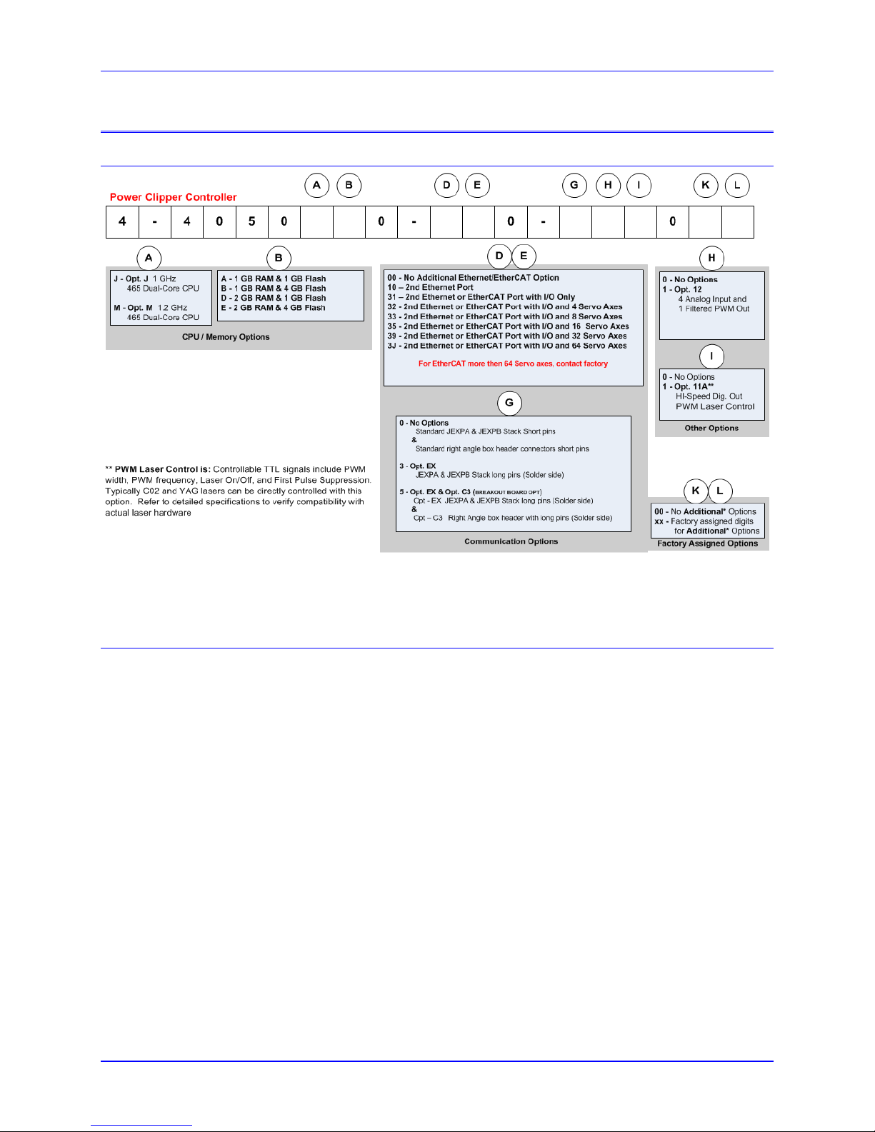
^4 4-4050xx0-xx0-xxx0xx
April 15, 2016
DELTA TAU
Data Systems, Inc.
NEW IDEAS IN MOTION …
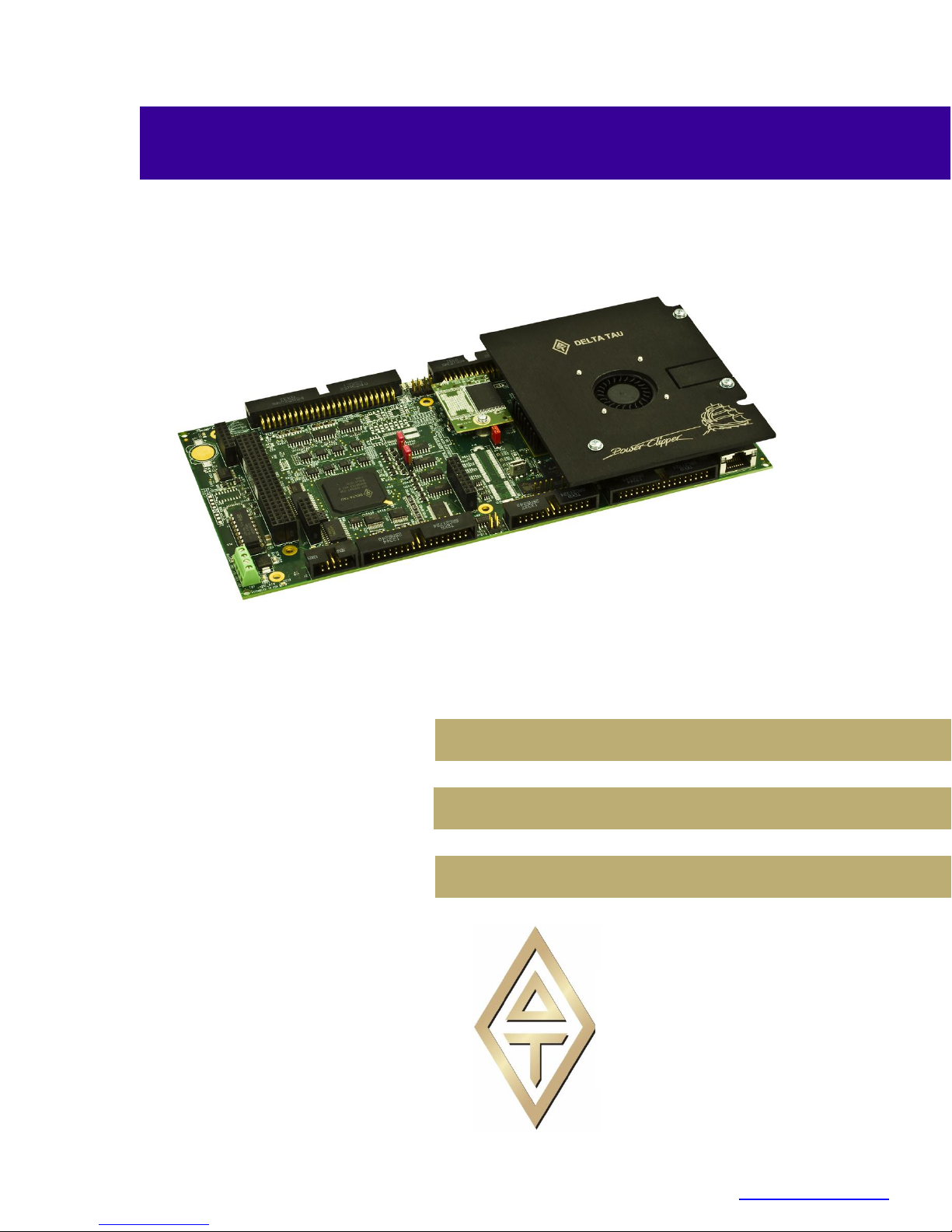
^2 Power PMAC Clipper
Page 2

Power PMAC Clipper User Manual
Copyright Information
© 2016 Delta Tau Data Systems, Inc. All rights reserved.
This document is furnished for the customers of Delta Tau Data Systems, Inc. Other uses
are unauthorized without written permission of Delta Tau Data Systems, Inc.
Information contained in this manual may be updated from time-to-time due to product
improvements, etc., and may not conform in every respect to former issues.
To report errors or inconsistencies, call or email:
Delta Tau Data Systems, Inc. Technical Support
Phone: (818) 717-5656
Fax: (818) 998-7807
Email: support@deltatau.com
Website: http://www.deltatau.com
Operating Conditions
All Delta Tau Data Systems, Inc. motion controller products, accessories, and amplifiers
contain static sensitive components that can be damaged by incorrect handling. When
installing or handling Delta Tau Data Systems, Inc. products, avoid contact with highly
insulated materials. Only qualified personnel should be allowed to handle this
equipment.
In the case of industrial applications, we expect our products to be protected from
hazardous or conductive materials and/or environments that could cause harm to the
controller by damaging components or causing electrical shorts. When our products are
used in an industrial environment, install them into an industrial electrical cabinet or
industrial PC to protect them from excessive or corrosive moisture, abnormal ambient
temperatures, and conductive materials. If Delta Tau Data Systems, Inc. products are
directly exposed to hazardous or conductive materials and/or environments, we cannot
guarantee their operation.
Page 3

Power PMAC Clipper User Manual
A Warning identifies hazards that could result in personal injury or
death. It precedes the discussion of interest.
Warning
Caution
A Caution identifies hazards that could result in equipment damage. It
precedes the discussion of interest.
Note
A Note identifies information critical to the understanding or use of
the equipment. It follows the discussion of interest.
Safety Instructions
Qualified personnel must transport, assemble, install, and maintain this equipment. Properly qualified
personnel are persons who are familiar with the transport, assembly, installation, and operation of
equipment. The qualified personnel must know and observe the following standards and regulations:
IEC364resp.CENELEC HD 384 or DIN VDE 0100
IEC report 664 or DIN VDE 0110
National regulations for safety and accident prevention or VBG 4
Incorrect handling of products can result in injury and damage to persons and machinery. Strictly adhere
to the installation instructions. Electrical safety is provided through a low-resistance earth connection. It
is vital to ensure that all system components are connected to earth ground.
This product contains components that are sensitive to static electricity and can be damaged by incorrect
handling. Avoid contact with high insulating materials (artificial fabrics, plastic film, etc.). Place the
product on a conductive surface. Discharge any possible static electricity build-up by touching an
unpainted, metal, grounded surface before touching the equipment.
Keep all covers and cabinet doors shut during operation. Be aware that during operation, the product has
electrically charged components and hot surfaces. Control and power cables can carry a high voltage,
even when the motor is not rotating. Never disconnect or connect the product while the power source is
energized to avoid electric arcing.
Page 4

Power PMAC Clipper User Manual
REVISION HISTORY
REV.
DESCRIPTION
DATE
CHG
APPVD
0
Preliminary
10/13/14
Sgm
1
Released
07/21/15
RN
RN
2
Update motor setup
04/15/16
Sgm
Sgm
Page 5

Page 6

Power PMAC Clipper User Manual
Table of Contents
INTRODUCTION ....................................................................................................................................... 9
Documentation .............................................................................................................................................. 9
Downloadable Power PMAC Script ........................................................................................................... 10
SPECIFICATIONS ................................................................................................................................... 11
Part Number ................................................................................................................................................ 11
Standard Configuration ............................................................................................................................... 11
Options ........................................................................................................................................................ 12
Accessories ................................................................................................................................................. 13
Environmental Specifications ..................................................................................................................... 16
Electrical Specifications .............................................................................................................................. 17
Digital Power Supply ............................................................................................................................. 17
DAC Outputs Power Supply .................................................................................................................. 17
Flags Power Supply ............................................................................................................................... 17
RECEIVING AND UNPACKING .......................................................................................................... 18
Use of Equipment ....................................................................................................................................... 18
MOUNTING .............................................................................................................................................. 19
Physical Specifications ............................................................................................................................... 20
Board Dimensions Rev101 .................................................................................................................... 20
Board Layout Rev101 ............................................................................................................................ 20
CONNECTIONS AND SOFTWARE SETUP ....................................................................................... 21
Default Jumper Configurations ................................................................................................................... 21
TB1 (JPWR): Power Supply Input.............................................................................................................. 21
J2: Serial Port .............................................................................................................................................. 23
J3: Machine Connector (JMACH1 Port) .................................................................................................... 24
Configuring Quadrature Encoders ........................................................................................................ 27
Wiring the DAC Output ......................................................................................................................... 29
Amplifier Enable Signal (AENAn/DIRn) ............................................................................................... 31
Amplifier Fault Signal (FAULT-) .......................................................................................................... 32
Analog Inputs ......................................................................................................................................... 33
Setting up the Analog (ADC) Inputs ...................................................................................................... 33
J4: Machine Connector (JMACH2 Port) .................................................................................................... 36
Overtravel Limits and Home Switches ................................................................................................... 37
Wiring the Limits and Flags .................................................................................................................. 37
Limits and Flags [Axis 1- 4] Structure Elements .................................................................................. 40
Step and Direction PFM Output (To External Stepper Amplifier) ........................................................ 41
Compare Equal Outputs ........................................................................................................................ 42
J7: Machine Connector (JMACH3 Port) .................................................................................................... 43
Brake Software Setup ............................................................................................................................. 44
Serial Encoder Software Setup .............................................................................................................. 44
J8: Thumbwheel Multiplexer Port (JTHW Port) ........................................................................................ 50
Table Of Contents vi
Page 7

Power PMAC Clipper User Manual
Thumbwheel Port Digital Inputs and Outputs ....................................................................................... 51
Configuring Multiplexed I/O on the JTHW port .................................................................................... 51
J9: General-Purpose Digital Inputs and Outputs (JOPT Port) .................................................................... 53
General Purpose I/O (J6) Structures ..................................................................................................... 54
J10: Handwheel and Pulse/Dir Connector (JHW/PD Port) ......................................................................... 56
Handwheel Encoder Software Setup...................................................................................................... 57
Handwheel PFM Software Setup ........................................................................................................... 57
Handwheel Option-12 DAC Software Setup .......................................................................................... 57
Handwheel 5th motor using the Option -12 DAC .................................................................................. 58
P2: USB Device Port .................................................................................................................................. 59
P20: EtherCat™/Ethernet Communications Port ........................................................................................ 59
P21: Ethernet Communications Port ........................................................................................................... 59
P17: USB Communications Port ................................................................................................................ 59
LED Indicators ............................................................................................................................................ 59
DRIVE - MOTOR SETUP ....................................................................................................................... 60
Filtered PWM Output (Analog ±10V) ........................................................................................................ 61
Clock Settings, Output Mode, Command Limit ..................................................................................... 61
Typical Motor Specific Settings ............................................................................................................. 61
Open Loop Test: Encoder/Decode ......................................................................................................... 62
Position-Loop PID Gains ...................................................................................................................... 63
Typical Settings for Four Channels of Filtered PWM Setup: ................................................................ 64
Pulse Frequency Modulation Output (Step and Direction) ......................................................................... 66
Multi-Channel Setup Elements .............................................................................................................. 66
Channel-Specific Setup Elements .......................................................................................................... 66
Motor-Specific Setup Elements .............................................................................................................. 67
Typical Settings for Four Channels of Open Loop PFM Setup: ............................................................ 68
ACC-24S3 4-CHANNEL AXIS EXPANSION STACK BOARD ......................................................... 70
Hardware Assembly .................................................................................................................................... 70
Default Jumper Configurations ................................................................................................................... 72
TB1 (JPWR): Power Supply Input.............................................................................................................. 73
J3: Machine Connector (JMACH1 Port) .................................................................................................... 74
Configuring Quadrature Encoders ........................................................................................................ 74
Wiring the DAC Output ......................................................................................................................... 74
Amplifier Enable Signal (AENAn/DIRn) ............................................................................................... 75
Amplifier Fault Signal (FAULT-) .......................................................................................................... 75
Analog Inputs ......................................................................................................................................... 75
Setting up the Analog (ADC) Inputs ...................................................................................................... 75
J4: Machine Connector (JMACH2 Port) .................................................................................................... 77
Limits and Flags [Axis 1- 4] Structure Elements .................................................................................. 77
Step and Direction PFM Output (To External Stepper Amplifier) ........................................................ 78
Compare Equal Outputs ........................................................................................................................ 78
J7: Machine Connector (JMACH3 Port) .................................................................................................... 79
Brake Software Setup ............................................................................................................................. 79
Serial Encoder Software Setup .............................................................................................................. 79
Table Of Contents vii
Page 8

Power PMAC Clipper User Manual
J8: Thumbwheel Multiplexer Port (JTHW Port) ........................................................................................ 80
Thumbwheel Port Digital Inputs and Outputs ....................................................................................... 80
Configuring Multiplexed I/O on the JTHW port .................................................................................... 80
J9: General-Purpose Digital Inputs and Outputs (JOPT Port) .................................................................... 81
General Purpose I/O (J6) Structures ..................................................................................................... 81
J10: Handwheel and Pulse/Dir Connector (JHW/PD Port) ......................................................................... 82
Handwheel Encoder Software Setup...................................................................................................... 82
Motor Setup Code ....................................................................................................................................... 83
Typical Settings for Four Channels of Filtered PWM Setup: ................................................................ 83
Typical Settings for Four Channels of Open Loop PFM Setup: ............................................................ 85
Table Of Contents viii
Page 9

Power PMAC Clipper User Manual
Note
The Power Clipper can also provide pulse and direction PFM output
signals to third-party stepper drives.
INTRODUCTION
The Power Clipper is a 4 axis motion controller combining the intelligence and capability of a Power
PMAC CPU with the convenience and savings of a low cost platform that is 100% hardware compatible
with its Turbo PMAC family member the Turbo PMAC Clipper.
It supports virtually any type of feedback device (with the optional ACC-84S and ACC-51S) and can
drive directly the following types of motors with the optional Clipper Drive Stack:
3-phase AC/DC brushless servo (synchronous) -- rotary/linear
2-phase stepper
DC brush
The number of axes in a Power Clipper application can be expanded to 8 with the optional ACC-24S3.
The Power Clipper comes with 32 general-purpose digital I/O points which can be expanded through the
optional ACC-34AA, ACC-24S3 or EtherCat. These can be configured as input or outputs in groups of
eight. The default factory settings are 16 inputs and 16 outputs.
The outstanding trajectory planner, built-in software PLCs (programmable in Power PMAC script and / or
C language), and other features make the Power Clipper a very scalable machine automation controllerdrive which can be virtually integrated in any kind of motion control application.
Documentation
In conjunction with this manual, the following manuals are essential for the proper operation and use of
the Power Clipper:
Power PMAC Software Reference Manual
Power PMAC User Manual
These manuals are available for download, to registered members, at Delta Tau Forums.
Introduction 9
Page 10

Power PMAC Clipper User Manual
Caution
Some code examples require the user to input specific information
pertaining to their system hardware. When user information is
required, a commentary ending with –User Input is inserted.
Caution
It is the user’s responsibility to manage the application’s PLCs
properly. The code samples are typically enclosed in a PLC buffer
with the user defined name ExamplePLC.
Downloadable Power PMAC Script
This manual contains downloadable code snippets in Power PMAC script. These examples can be copied
and pasted into the editor area of the IDE software. Care must be taken when using pre-configured Power
PMAC code, some information may need to be updated to match hardware or system specific
configurations. Downloadable code found in this manual is enclosed in the following format:
// Power PMAC script format example
GLOBAL MyCounter = 0; // Arbitrary global variable, counter
GLOBAL MyCycles = 10; // Arbitrary global variable, number of cycles --User Input
OPEN PLC ExamplePLC // Open PLC buffer
WHILE (MyCounter < MyCycles) // While counter is less than number of cycles
{ // Start while loop
MyCounter ++ // Increment MyCounter by 1
} // End while loop
MyCounter = 0 // Reset Mycounter
DISABLE PLC ExamplePLC // Disable PLC
CLOSE // Close PLC buffer
It is the user’s responsibility to use the PLC examples presented in this manual properly, and incorporate
the statement code in the application project accordingly.
Introduction 10
Page 11
Power PMAC Clipper User Manual
SPECIFICATIONS
Part Number
The Power Clipper comes standard with a powerful set of hardware and software capabilities, plus a full
set of options and accessories.
Standard Configuration
The standard configuration of the Power Clipper provides the following features:
CPU
1.0 GHz Dual-Core Power PC 465EX CPU
Memory
1 GB DDRAM3 active memory, 1 GB NAND Flash non-volatile memory
Communications Ports
100 Mbps Ethernet port for host communications
RS-232 port
USB 2.0 Host port
USB 2.0 Device port
Servo Interface
4 channels servo interface, each including:
Quadrature encoder (with index) interface
UVW digital Hall sensor interface
Specifications 11
Page 12

Power PMAC Clipper User Manual
Serial encoder interface, with software selectable protocol, from the following:
o SSI
o EnDat 2.1/2.2 (2.1-compatible features only) with delay compensation
o Hiperface
o Yaskawa Sigma I
o Yaskawa II/III/V (no position reset or fault clear)
o Tamagawa FA-Coder
o Panasonic (no servo clock output)
o Mitutoyo
o Kawasaki
o Basic quadrature (no index, no capture)
Filtered PWM analog output (~13-bit resolution)
Pulse & direction output
Input flags (home, +limit, -limit, user) at 5V CMOS levels (24V tolerant)
Position compare (EQU) output
Amplifier-enable output and amplifier-fault input flags
Brake control output
General-Purpose I/O
JIO Port: 16 5V CMOS I/O points, direction selectable by byte (flat cable connection to Opto-22
or equivalent)
JTHW Port: 16 5V CMOS I/O points, direction selectable by byte (flat cable connection to Delta
Tau ACC-34x boards)
Stacking Connector Configuration
The standard configuration of the Power Clipper comes with:
The “short-pin” version of the expansion port connectors. These support accessories that stack on
top of the Power Clipper (e.g. ACC-24S3, 8AS, 8FS, 8TS, 51S, and 84S), but not those that stack
under it (e.g. LV Stack Amplifier).
The “short-pin” version of the right-angle box header connectors. These support flat cable
connections to field wiring, but not connections through breakout boards that stack under it (e.g.
Delta Tau’s stack breakout board or custom breakout boards).
Options
The following options can be ordered for the Power Clipper board:
CPU Options
1.2 GHz Dual-Core Power PC 465EX CPU
Memory Options
The following optional memory configurations can be ordered:
1 GB DDRAM3 active memory, 4 GB NAND Flash non-volatile memory
2 GB DDRAM3 active memory, 1 GB NAND Flash non-volatile memory
2 GB DDRAM3 active memory, 4 GB NAND Flash non-volatile memory
Specifications 12
Page 13

Power PMAC Clipper User Manual
Communications Port Options
Added Ethernet Port ,1 Gbps, EtherCAT compatible
EtherCAT Software License Options (require 2nd Ethernet port option)
When the second Ethernet port option is ordered, software license options can also be ordered to support
EtherCAT data transfers. The following software license options can be ordered:
EtherCAT I/O only (no servo axes)
EtherCAT I/O with 4 servo axes
EtherCAT I/O with 8 servo axes
EtherCAT I/O with 16 servo axes
EtherCAT I/O with 32 servo axes
EtherCAT I/O with 64 servo axes
Analog I/O Option
4-channels 12-bit ADC plus 1 additional channel filtered-PWM analog output (~13 bits)
Digital Laser Control Output Option
Programmable PWM laser-control IC with output drivers
Stacking Connector Options
“Long-pin” version of expansion-port connectors to support communications interface to boards
that stack under Power Clipper (e.g. LV Stack Amplifier). “Short-pin” version of right-angle box
header connectors that only support flat cable connections for field wiring.
“Long-pin” version of expansion-port connectors to support communications interface to boards
that stack under Power Clipper (e.g. LV Stack Amplifier). “Long-pin” version of right-angle box
header connectors to support connections through breakout boards that stack under it (e.g. Delta
Tau’s stack breakout board or custom breakout boards).
Accessories
The following accessory boards can be used with the Power Clipper board:
ACC-24S3 4-Channel Axis Expansion Stack Board
The ACC-24S3 can be stacked on top of the Power Clipper to provide an additional 4 channels of servo
interface circuitry and 32 additional digital I/O points equivalent to what is on the Power Clipper itself.
Optionally, it can provide 4 additional 12-bit ADCs and 1 additional filtered-PWM analog output (~13
bits).
Only one ACC-24S3 board can be used with the Power Clipper. If it is installed on top of the Power
Clipper, only one small stack board (ACC-8AS, 8FS, 8TS, 51S, 84S) can be installed directly on the
Power Clipper between it and the ACC-24S3. Two of these small stack boards can be installed on top of
the ACC-24S3.
ACC-8AS 4-Channel 2-Phase 16-Bit True-DAC Stack Board
The ACC-8AS can be stacked on top of either the Power Clipper or the ACC-24S3 to provide 4 channels
of 16-bit “true DAC” output with two DACs per channel. This board is mainly used for very high-
precision servo applications that require more resolution than the filtered-PWM analog outputs on the
Specifications 13
Page 14

Power PMAC Clipper User Manual
Power Clipper and the ACC-24S3. The dual-phase DAC outputs support the “sine-wave output” control
mode where brushless motor commutation is performed by the Power PMAC.
The true-DAC outputs of the ACC-8AS can be used simultaneously with the filtered-PWM analog output
on the same channel of the Power Clipper or ACC-24S3 without interference.
ACC-8FS 4-Channel Direct-PWM Interface Stack Board
The ACC-8FS can be stacked on top of either the Power Clipper or the ACC-24S3 to provide 4 channels
of 3-phase direct-PWM output through Mini-D 36-pin connectors to “power block” amplifiers. This board
is mainly used for applications where the Power Clipper is performing both the commutation and digital
current loop closure for brushless motors.
The 3-phase PWM outputs of the ACC-8FS cannot be used simultaneously with the filtered-PWM analog
output on the same channel of the Power Clipper or ACC-24S3. However, they can be used
simultaneously with the PFM (pulse-and-direction) outputs of the same channel of the Power Clipper or
ACC-24S3 without interference.
The ADC inputs passed through the ACC-8FS can be used simultaneously with the Option 12 ADCs on
the Power Clipper or ACC-24S3 without interference.
ACC-8TS Bridge Stack Board to ACC-28B ADCs
The ACC-8TS can be stacked on top of either the Power Clipper or the ACC-24S3 to provide a flat-cable
interface to one or two ACC-28B 4-channel 16-bit ADC boards.
The ADC inputs passed through the ACC-8TS can be used simultaneously with the Option 12 ADCs on
the Power Clipper or ACC-24S3 without interference.
ACC-51S 4-Channel Sinusoidal Encoder Interpolator Stack Board
The ACC-51S can be stacked on top of either the Power Clipper or the ACC-24S3 to provide 4 channels
of sinusoidal encoder interpolation with 16,384 states per line.
The sinusoidal encoder inputs passed through the ACC-51S cannot be used simultaneously with the main
quadrature encoder inputs of the same channel of the Power Clipper or ACC-24S3 without interference.
However, it is possible to pass digital quadrature signals through the ACC-51S.
ACC-84S 4-Channel Serial Encoder Interface Stack Board
The ACC-84S can be stacked on top of either the Power Clipper or the ACC-24S3 to provide 4 channels
of serial-encoder interface. The ACC-84S can be ordered from the factory with a single encoder protocol
installed from the following list:
EnDat2.2 with additional information, no delay compensation
BiSS-B/C
Yaskawa II/III/V with position reset and fault clear
Tamagawa FA-Coder with servo clock output
Matsushita (Nikon D)
Mitsubishi
SSI (no capabilities over Power Clipper’s built-in interface)
Panasonic (no capabilities over Power Clipper’s built-in interface)
Mitutoyo (no capabilities over Power Clipper’s built-in interface)
Specifications 14
Page 15

Power PMAC Clipper User Manual
The serial-encoder inputs on the ACC-84S can be used simultaneously with the serial-encoder input on
the same channel of the Power Clipper or ACC-24S3 without interference.
Clipper 4-Channel Breakout Board
The Clipper 4-Channel Breakout Board can be stacked under the Power Clipper board to provide discrete
connectors for each channel and each I/O functionality. It also provides optical isolation and driver
circuitry for axis flags and general-purpose I/O.
The Clipper 4-Channel Breakout Board cannot be used to provide connections for the ACC-24S3 Axis
Expansion Board.
Clipper 4-Channel LV Stack Amplifier
The Clipper 4-Channel LV (Low-Voltage) Stack Amplifier can be stacked under the Power Clipper board
or its 4-Channel Breakout board to provide the power amplifier circuitry for 4 motors with up to 60VDC
supply and a rating of up to 5A(rms) continuous, 15A(rms) peak. Each motor can be 1-phase (e.g. DC
brush motor), 2-phase (e.g. stepper motor), or 3-phase (e.g. brushless servo motor).
The Clipper 4-Channel LV Stack Amplifier cannot be used to provide the power stage for the ACC-24S3
Axis Expansion Board.
ACC-28B 4-Channel 16-Bit ADC Board
The ACC-28B provides 2 or 4 channels of 16-bit A/D converters on a DIN-rail mountable board. It can
be connected to the Power Clipper or ACC-24S3 by flat cable through an ACC-8TS bridge stack board.
ACC-34 Family Multiplexed I/O Boards
The ACC-34 family of multiplexed I/O boards each provide 32 general-purpose digital inputs and 32
general-purpose digital outputs. Up to 32 of these DIN-rail mountable boards can be connected to the
JTHW multiplexer port on the Power Clipper through standard flat cables. Due to the multiplexed access
and serial data transfers, these I/O points cannot react as quickly as the I/O points on the Power Clipper
itself.
Specifications 15
Page 16

Power PMAC Clipper User Manual
Specification
Description
Range
Ambient operating Temperature
EN50178 Class 3K3 – IEC721-3-3
Minimum operating temperature
0°C (32°F)
Maximum operating temperature
45°C (113°F)
Storage Temperature Range
EN 50178 Class 1K4 – IEC721-3-1/2
Minimum Storage temperature
-25°C (-13°F)
Maximum Storage temperature
70°C (158°F)
Humidity Characteristics with
NO condensation and NO formation of ice
IEC721-3-3
Minimum Relative Humidity
5% HU
Maximum Relative Humidity
up to 35°C (95°F)
95% HU
Maximum Relative Humidity
from 35°C up to 50°C (122°F)
85% HU
De-rating for Altitude
0 ~ 1000m (0 ~ 3300ft)
No de-rating
1000 ~ 3000m (3300 ~ 9840ft)
-0.01%/m
3000 ~ 4000m (9840 ~ 13000ft)
-0.02%/m
Environment
ISA 71-04
Degree 2 environments
Atmospheric Pressure
EN50178 class 2K3
70 KPa to 106 KPa
Shock
Unspecified
Vibration
Unspecified
Air Flow Clearances
3" (76.2mm) above and below unit for air flow
Cooling
Natural convection and built-in CPU fan
Standard IP Protection
IP20
IP 55 can be evaluated for custom applications
Environmental Specifications
Specifications 16
Page 17

Power PMAC Clipper User Manual
Note
Clipper base board requires 2.75A with no other connections. Size
your application accordingly to your encoder load. The above assumes
typical encoder loads at ~100mA per encoder.
Electrical Specifications
Digital Power Supply
The +5V and ground reference lines from the power supply should be connected to TB1 terminal block of
the Power PMAC Clipper board using 18 AWG stranded wire. The power requirement (± 5%) is:
+5 V (20W) @ 3.5 A (Four-channel configuration with a typical load of encoders)
+5 V (20W) @ 5.5 A (Eight-channel ACC-24S3 configuration with a typical load of encoders)
DAC Outputs Power Supply
The ±12V lines from the supply, including the ground reference, can be brought in from the TB1 terminal
block.
+12 to +15 V (4.5W) @ 0.30 A (Four-channel configuration with a typical DAC load)
-12 to -15 V (3.8W) @ 0.25 A
+12 to +15 V (4.5W) @ 0.50 A (Eight-channel configuration with a typical DAC load)
-12 to -15 V (3.8W) @ 0.45 A
Flags Power Supply
Each channel of PMAC has five dedicated digital inputs on the machine connector: PLIMn, MLIMn
(overtravel limits), HOMEn (home flag), FAULTn (amplifier fault), and USERn. A power supply from 5
to 24V must be used to power the circuits related to these inputs. This power supply can be the same
used to Power PMAC Clipper and can be connected from the TB1 terminal block.
Specifications 17
Page 18

Power PMAC Clipper User Manual
RECEIVING AND UNPACKING
Delta Tau products are thoroughly tested at the factory and carefully packaged for shipment. When the
Power PMAC Clipper is received, there are several things to be done immediately:
Observe the condition of the shipping container and report any damage immediately to the
commercial carrier that delivered the board.
Remove the Power PMAC Clipper from the shipping container and remove all packing materials.
Check all shipping material for connector kits, documentation, or other small pieces of
equipment. Be aware that some connector kits and other equipment pieces may be quite small
and can be accidentally discarded if care is not used when unpacking the equipment. The
container and packing materials may be retained for future shipment.
Verify that the part number of the board received is the same as the part number listed on the
purchase order.
Inspect for external physical damage that may have been sustained during shipment and report
any damage immediately to the commercial carrier that delivered the board.
Electronic components in this product are design-hardened to reduce static sensitivity. However,
use proper procedures when handling the equipment.
If the Power PMAC Clipper is to be stored for several weeks before use, be sure that it is stored
in a location that conforms to published storage humidity and temperature specifications.
Use of Equipment
The following restrictions will ensure the proper use of the Power PMAC Clipper:
The components built into electrical equipment or machines can be used only as integral
components of such equipment.
The Power PMAC Clipper must not be operated on power supply networks without a ground or
with an asymmetrical ground.
If the Power PMAC Clipper is used in residential areas, or in business or commercial premises,
implement additional filtering measures.
The Power PMAC Clipper may be operated only in a closed switchgear cabinet, taking into
account the ambient conditions defined in the environmental specifications.
Delta Tau guarantees the conformance of the Power PMAC Clippers with the standards for industrial
areas stated in this manual, only if Delta Tau components (cables, controllers, etc.) are used.
Receiving and Unpacking 18
Page 19

Power PMAC Clipper User Manual
Caution
Unit must be installed in an enclosure that meets the environmental IP
rating of the end product (ventilation or cooling may be necessary to
prevent enclosure ambient from exceeding 45° C [113° F]).
MOUNTING
The location of the Power PMAC Clipper is important. Installation should be in an area that is protected
from direct sunlight, corrosives, harmful gases or liquids, dust, metallic particles, and other contaminants.
Exposure to these can reduce the operating life and degrade performance of the board.
Several other factors should be carefully evaluated when selecting a location for installation:
For effective cooling and maintenance, the Power PMAC Clipper should be mounted on a
smooth, non- flammable vertical or horizontal surface.
At least 10 mm (0.4 inches) top and bottom clearance must be provided for air flow.
Temperature, humidity and Vibration specifications should also be taken in account.
The Power PMAC Clipper can be mounted as a stand-alone controller using standoffs. At each of the
four corners of the board and at the center edges, there are mounting holes that can be used for this.
If the Power PMAC Clipper is mounted to a back panel, the back panel should be unpainted and
electrically conductive to allow for reduced electrical noise interference. The back panel should be
machined to accept the standoffs pattern of the board.
The board can be mounted to the back panel using four standoffs and internal-tooth lock washers. It is
important that the teeth break through any anodization on the board’s mounting gears to provide a good
electrically conductive path in as many places as possible. Mount the board on the back panel so there is
airflow at both the top and bottom areas of the board (at least 0.4 inches).
Mounting 19
Page 20
Power PMAC Clipper User Manual
Physical Specifications
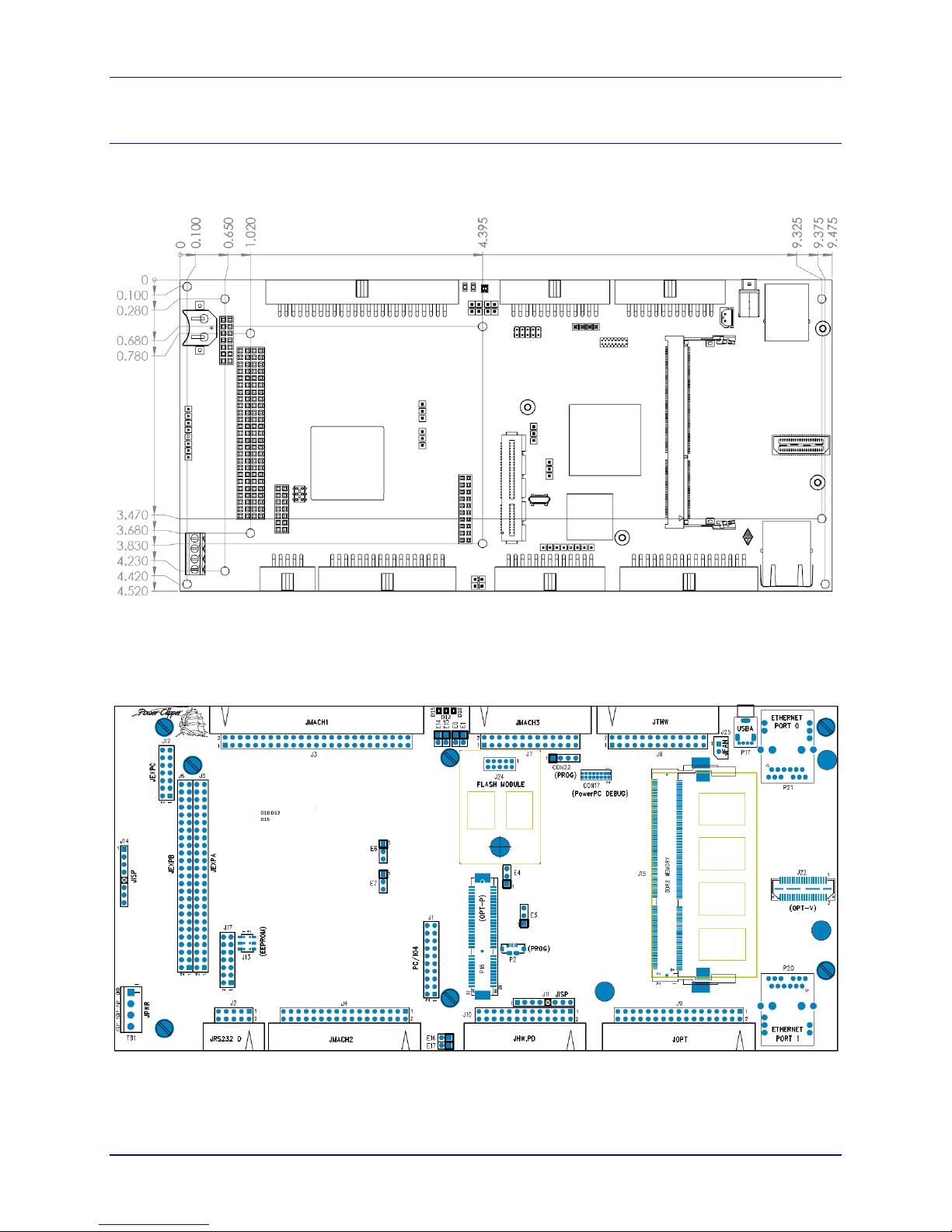
Board Dimensions Rev101
Top View
Board Layout Rev101
Top View
Mounting are holes shown with screw heads.
Mounting 20
Page 21

Power PMAC Clipper User Manual
WARNING
Installation of electrical equipment is subject to many regulations
including national, state, local, and industry guidelines and rules.
The following are general recommendations but it is important
that the integration be carried out in accordance with all
regulations pertaining to the installation.
Jumper
Position Description
Note
E0
CPU RESET
Do Not Install
E1
Install E1 to bypass watchdog timer for bootstrap
software load.
Do Not Install
E4
Factory use only, should always be 1-2.
Do Not change
E5
Not currently used
Not Installed
E6
Selection between handwheel input or serial encoder
input on Gate3[i].Chan[0].SerialEncDataA
1-2 FOR SENC1
2-3 ENC-HW-1
Default 1-2
E7
Selection between handwheel input or serial encoder
input on Gate3[i].Chan[1].SerialEncDataA
1-2 FOR SENC2
2-3 ENC-HW-2
Default 1-2
E14
Install to make GPIO 0-7 lines inputs
Remove jumper to make GPIO 0-7 lines outputs
Installed (Required for MuxIO)
E15
Install to make GPIO 8-15 lines inputs
Remove jumper to make GPIO 8-15lines outputs
Not Installed (Required for
MuxIO)
E16
Install to make GPIO 16-23 lines inputs
Remove jumper to make GPIO 16-23 lines outputs
Not Installed
E17
Install to make GPIO 24-31 lines inputs
Remove jumper to make GPIO 24-31 lines outputs
Installed
TB1 (JPWR): Power Supply
4-Pin Terminal Block
Pin#
Symbol
Function
Description
Notes
1
GND
Common
Digital Common
CONNECTIONS AND SOFTWARE SETUP
Default Jumper Configurations
The following table shows the default jumper configurations:
TB1 (JPWR): Power Supply Input
This 4-pin terminal block is used to bring the 5VDC logic power and +/-12VDC DAC supply into the
Power PMAC Clipper.
Connections and Software Setup 21
Page 22

Power PMAC Clipper User Manual
2
+5V
Input
Logic Voltage
Supplies all PMAC digital circuits
3
+12V
Input
DAC Supply Voltage
Ref to Digital GND
4
-12V
Input
DAC Supply Voltage
Ref to Digital GND
Note
For +5V and GND, 18 gauge (AWG) stranded wire is recommended.
For +12V and -12V, a minimum of 22 gauge (AWG) stranded wire is
recommended.
Connections and Software Setup 22
Page 23

Power PMAC Clipper User Manual
J2 (JRS232) Serial Port Connector
10-Pin Header
56341
2
9107
8
Pin#
Symbol
Function
Description
Notes
1
No Connection
2
DTR
Bidirect
Data Terminal Ready
Tied to "DSR"
3
TXD/
Output
Send Data
Host receive data
4
CTS
Input
Clear to Send
Host ready bit
5
RXD/
Input
Receive Data
Host transmit data
6
RTS
Output
Request to Send
PMAC ready bit
7
DSR
Bidirect
Data Set Ready
Tied to "DTR"
8
No Connection
9
GND
Common
Digital Common
10
RESET_SW#
Input
Hardware CPU Reset
Ground is Reset
J2: Serial Port
This connector allows communicating with Power PMAC Clipper from a host computer through a RS232 port. Delta Tau provides the Accessory 3L cable that connects the PMAC to a DB-9 connector.
10-pin female flat cable connector T&B Ansley P/N 609-1041
Standard flat cable stranded 10-wire T&B Ansley P/N 171-10
Connections and Software Setup 23
Page 24

Power PMAC Clipper User Manual
J3 (JMACH1): Machine Port Connector
50-Pin Header
495047484546434441423940373835363334313229302728252623242122192017181516131411129107856341
2
Pin#
Symbol
Function
Description
Notes
1
+5V
Output
+5V Power
For encoders, 1
2
+5V
Output
+5V Power
For encoders, 1
3
GND
Common
Digital Common
For encoders, 1
4
GND
Common
Digital Common
For encoders, 1
5
CHA1
Input
Encoder A Channel Positive
2
6
CHA2
Input
Encoder A Channel Positive
2
7
CHA1/
Input
Encoder A Channel Negative
2,3
8
CHA2/
Input
Encoder A Channel Negative
2,3
9
CHB1
Input
Encoder B Channel Positive
2
10
CHB2
Input
Encoder B Channel Positive
2
11
CHB1/
Input
Encoder B Channel Negative
2,3
12
CHB2/
Input
Encoder B Channel Negative
2,3
13
CHC1
Input
Encoder C Channel Positive
2
14
CHC2
Input
Encoder C Channel Positive
2
15
CHC1/
Input
Encoder C Channel Negative
2,3
16
CHC2/
Input
Encoder C Channel Negative
2,3
17
CHA3
Input
Encoder A Channel Positive
2
18
CHA4
Input
Encoder A Channel Positive
2
19
CHA3/
Input
Encoder A Channel Negative
2,3
20
CHA4/
Input
Encoder A Channel Negative
2,3
21
CHB3
Input
Encoder B Channel Positive
2
22
CHB4
Input
Encoder B Channel Positive
2
23
CHB3/
Input
Encoder B Channel Negative
2,3
24
CHB4/
Input
Encoder B Channel Negative
2,3
25
CHC3
Input
Encoder C Channel Positive
2
26
CHC4
Input
Encoder C Channel Positive
2
27
CHC3/
Input
Encoder C Channel Negative
2,3
J3: Machine Connector (JMACH1 Port)
The primary machine interface connector is JMACH1, labeled J3 on the Power PMAC Clipper. It
contains the pins for four channels of machine I/O: analog outputs, incremental encoder inputs, amplifier
fault and enable signals and power-supply connections.
Connections and Software Setup 24
Page 25

Power PMAC Clipper User Manual
28
CHC4/
Input
Encoder C Channel Negative
2,3
29
DAC1
Output
Analog Output Positive 1
4
30
DAC2
Output
Analog Output Positive 2
4
31
DAC1/
Output
Analog Output Negative 1
4,5
32
DAC2/
Output
Analog Output Negative 2
4,5
33
AENA1/
Output
Amplifier-Enable 1
34
AENA2/
Output
Amplifier -Enable 2
35
FAULT1/
Input
Amplifier -Fault 1
36
FAULT2/
Input
Amplifier -Fault 2
37
DAC3
Output
Analog Output Positive 3
4
38
DAC4
Output
Analog Output Positive 4
4
39
DAC3/
Output
Analog Output Negative 3
4,5
40
DAC4/
Output
Analog Output Negative 4
4,5
41
AENA3/
Output
Amplifier -Enable 3
42
AENA4/
Output
Amplifier -Enable 4
43
FAULT3/
Input
Amplifier -Fault 3
44
FAULT4/
Input
Amplifier -Fault 4
45
ADCIN_1
Input
Analog Input 1
46
ADCIN_2
Input
Analog Input 2
47
FLT_FLG_V
Input
Amplifier Fault pull-up V+
48
GND
Common
Digital Common
49
+12V
Input
DAC Supply Voltage
7
50
-12V
Input
DAC Supply Voltage
7
Note
Note 1: These lines can be used as +5V power supply inputs to power
PMAC’s digital circuitry.
Note 2: Referenced to digital common (GND). Maximum of ±12V
permitted between this signal and its complement.
Note 3: Leave this input floating if not used (i.e. digital single-ended
encoders).
Note 4: ±10V, 10 mA max, referenced to common ground (GND).
Note 5: Leave floating if not used. Do not tie to GND.
Note 7: Can be used to provide input power when the TB1 connector is
not being used.
50-pin female flat cable connector T&B Ansley P/N 609-5041. Standard flat cable stranded 50-wire T&B
Ansley P/N 171-50. Phoenix varioface module type FLKM 50 (male pins) P/N 22 81 08 9
Connections and Software Setup 25
Page 26
Power PMAC Clipper User Manual
Note
Use an encoder cable with high quality shield.
Channel A
Channel B
The standard encoder inputs on the Power PMAC Clipper are designed for differential quadrature type
signals.
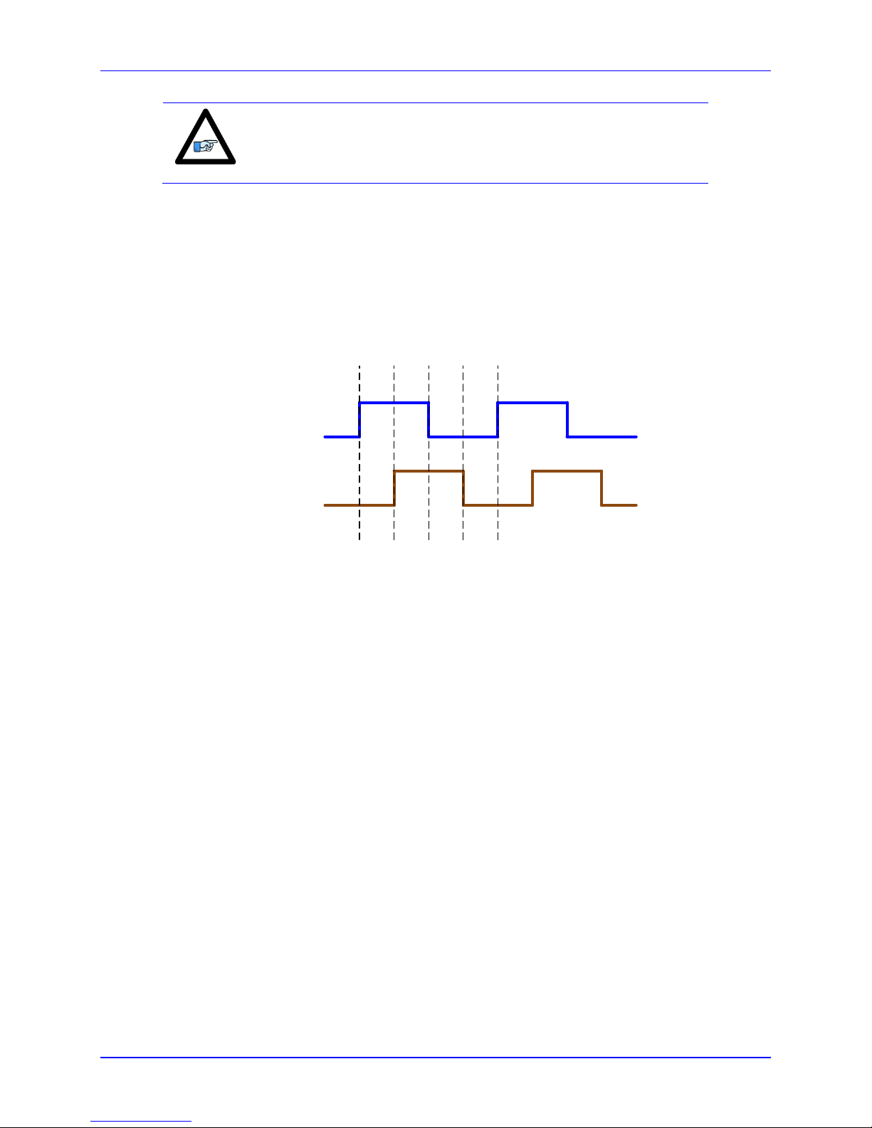
Quadrature encoders provide two digital signals to determine the position of the motor. Each nominally
with 50% duty cycle, and nominally 1/4 cycle apart. This format provides four distinct states per cycle of
the signal, or per line of the encoder. The phase difference of the two signals permits the decoding
electronics to discern the direction of travel, which would not be possible with a single signal.
Typically, these signals are 5V TTL/CMOS level whether they are single-ended or differential.
Differential signals can enhance noise immunity by providing common mode noise rejection. Modern
design standards virtually mandate their use in industrial systems.
Connections and Software Setup 26
Page 27

Power PMAC Clipper User Manual
Encoder shield
25 23
24
21
22
19
20
17
18
15
16
13
14
11
12
9
10
7
8
5
6
3
4
1
2
B-
C-
C+
B+
A-
A+
GND
+5V
J3(JMACH1)
Note
For single-ended encoders, leave the complementary signal pins
floating – do not ground them. Alternately, some open collector
single ended encoders may require tying the negative pins to
ground in series with a 1-2 KOhm resistors.
Some motor manufacturers bundle the hall sensors with the
motor-lead cable. The hall sensors must be brought into J7
connector.
Differential Quadrature Encoder Wiring for Channel #1
Configuring Quadrature Encoders
The Power Clipper default settings are configured for quadrature encoders. Minimal setup is required to
configure them; quadrature encoder signals are processed as a single 32-bit read in the encoder
conversion table (ECT). 1/T extension is done in the Gate3 "hardware".
The default ECT settings for the first incremental quadrature encoder will be:
EncTable[1].type = 1; // Single 32-bit read
EncTable[1].pEnc = Clipper[0].Chan[0].ServoCapt.a; // Primary source, ch 1 Servo Capture
EncTable[1].pEnc1 = Sys.Pushm; // Secondary source, none
EncTable[1].index1 = 0; // left shift, none
EncTable[1].index2 = 0; // right shift, none
EncTable[1].index3 = 0; //
EncTable[1].index4 = 0; //
EncTable[1].ScaleFactor = 1/256; // Scale Factor, LSB location
Connections and Software Setup 27
Page 28

Power PMAC Clipper User Manual
Note
The hardware 1/T extension produces 8 bits of fractional data, thus the
(1 / 256) 0.00390625 scale factor.
Channel
Number
Quadrature Encoder
Source Address
1
Clipper[0].Chan[0].ServoCapt.a
2
Clipper[0].Chan[1].ServoCapt.a
3
Clipper[0].Chan[2].ServoCapt.a
4
Clipper[0].Chan[3].ServoCapt.a
Note
The top level structure name “Clipper” is an alias for “Gate3”. Either
may be used when referring to any “Gate3” structures with the Power
Clipper. This manual will use “Clipper”.
Warning
Loss of the feedback sensor signal is potentially a very dangerous
condition in closed-loop control, because the servo loop no longer has
any idea what the true physical position of the motor is – usually it
thinks it is “stuck” – and it can react wildly, often causing a runaway
condition.
Activating the corresponding channel is sufficient to display counts in the position window when the
motor / encoder shaft is moved by hand.
Motor[1].ServoCtrl = 1; // Channel activation
The position and velocity source(s) must be pointing to the proper ECT result. With quadrature encoders,
they are initialized by the firmware as:
Motor[1].pEnc = EncTable[1].a; // Position
Motor[1].pEnc2 = EncTable[1].a; // Velocity
Motor[2].pEnc = EncTable[2].a; // Position
Motor[2].pEnc2 = EncTable[2].a; // Velocity
Motor[3].pEnc = EncTable[3].a; // Position
Motor[3].pEnc2 = EncTable[3].a; // Velocity
Motor[4].pEnc = EncTable[4].a; // Position
Motor[4].pEnc2 = EncTable[4].a; // Velocity
Counts per User Units
With quadrature encoders, the number of counts per user units (usually revolution) is 4 times the specified
number of lines of the encoder. For example, a 1,000–line rotary encoder should result in 4,000 motor
units per revolution.
Quadrature Encoder Count Error
With quadrature encoders, the Power Clipper has the capability of trapping encoder count (loss) errors.
This is described in detail in the Encoder Count Error section of this manual.
Quadrature Encoder Loss Detection
Connections and Software Setup 28
Page 29

Power PMAC Clipper User Manual
Note
Note the distinction between the encoder count error, which reports
loss of counts due to bad transitions of the quadrature signals, and
encoder loss, which indicates that one or more quadrature signals are
completely missing.
25 23
Analog
Device
COM
DAC1+
49
50
47
48
45
46
43
44
41
42
39
40
37
38
35
36
33
34
31
32
29
30
27
28 26
Single Ended DAC Output
J3 (JMACH1)
Analog
Device
COM
DAC1-
DAC1+
25 2349
50
47
48
45
46
43
44
41
42
39
40
37
38
35
36
33
34
31
32
29
30
27
28 26
Differential DAC Output
J3 (JMACH1)
Note
The analog outputs are intended to drive high-impedance inputs with
no significant current draw (10mA max). The 220 output resistors
will keep the current draw lower than 50 mA in all cases and prevent
damage to the output circuitry, but any current draw above 10 mA can
result in noticeable signal distortion. Software setup for analog outputs
can be found in the Drive-Motor setup section.
With quadrature encoders, the Power Clipper has the capability of detecting the loss of an encoder signal.
This is described in detail in the Encoder Loss Detection section of this manual.
Wiring the DAC Output
Example for Clipper Channel #1
Connections and Software Setup 29
Page 30

Power PMAC Clipper User Manual
Connections and Software Setup 30
Page 31

Power PMAC Clipper User Manual
25 2349
50
47
48
45
46
43
44
41
42
39
40
37
38
35
36
33
34
31
32
29
30
27
28 26
J3 (JMACH1)
AENA1
GND
}
Connect to the amplifier
enable input
Amplifier Enable Signal (AENAn/DIRn)
Most amplifiers have an enable/disable input that permits complete shutdown of the amplifier regardless
of the voltage of the command signal. PMAC’s AENA line is meant for this purpose. AENA1- is pin 33.
This signal is an open-collector output and an external 3.3 k pull-up resistor can be used if necessary.
Example for Clipper Channel #1
Connections and Software Setup 31
Page 32

Power PMAC Clipper User Manual
J3 (JMACH1)
5 – 24 VDC
Power Supply
25 2349
50
47
48
45
46
43
44
41
42
39
40
37
38
35
36
33
34
31
32
29
30
27
28 26
FAULT1-
}
Connect to the amplifier
fault output
+ -
Amplifier Fault Signal (FAULT-)
This input can take a signal from the amplifier so PMAC knows when the amplifier is having problems,
and can shut down action.
The polarity is programmable with Motor[x].AmpFaultLevel (Motor[1].AmpFaultLevel for motor 1) and the
return signal is ground (GND). FAULT1- is pin 35. With the default setup, this signal must actively be
pulled low for a fault condition. In this setup, if nothing is wired into this input, PMAC will consider the
motor not to be in a fault condition.
Example for Clipper Channel #1
Connections and Software Setup 32
Page 33

Power PMAC Clipper User Manual
}
+/- 10V Analog Signal
ADCIN_1
J3 (JMACH1)
495047484546434441423940373835363334313229302728252623242122192017181516131411129107856341
2
ADCIN_n/
Connector
Structure
Address
ADCIN_1, J3
Clipper[0].Chan[0].AdcEnc[0]
$900030
ADCIN_2, J3
Clipper[0].Chan[0].AdcEnc[1]
$900034
ADCIN_3, J7
Clipper[0].Chan[0].AdcEnc[2]
$900038
ADCIN_4, J7
Clipper[0].Chan[0].AdcEnc[3]
$90003C
Analog Inputs
The Power PMAC Clipper provides four 12-bit analog inputs with a ±10Vdc range. The first two inputs
are on JMACH1 pins 45 (ADCIN_1) and 46 (ADCIN_2) referenced to pin 3 (digital ground). Inputs 3
and 4 are on the JMACH3 connector pins 1 (ADCIN_3) and 2 (ADCIN_4). These are also referenced to
digital ground.
Example for Analog Input 1
Example for Analog Input 3
Setting up the Analog (ADC) Inputs
The analog inputs accept ±10V single-ended signals only.
The ADC data resides in the upper 12 bits of the 32-bit structure elements in the following table. The
structure elements do not allow bit definitions of the upper 12 bits, hence scaling (shifting) would be
required to obtain the raw ADC data. Using the explicit address registers with PTR definitions is one
alternative:
Connections and Software Setup 33
Page 34

Power PMAC Clipper User Manual
Note
The explicit address register(s) can be found by subtracting Sys.piom
from Clipper[0].Chan[0].AdcEnc[n].a (n=0-3).
Note
The ADC input data must be in the “unpacked” format to be read
properly; Clipper[0].Chan[0].PackInData = 0.
Single-Ended
[VDC]
Software
Counts
-10
-2048 0 0
10
+2048
Raw ADC Data (in bits)
Sys.WpKey = $AAAAAAAA; // Disable Write-Protection
Clipper[0].Chan[0].PackInData = 0; // Unpack Input Data all ADCs J3, J7
PTR ADCIN_1->S.IO:$900030.20.12; // ADCIN_1 J3 [bits]
PTR ADCIN_2->S.IO:$900034.20.12; // ADCIN_2 J3 [bits]
PTR ADCIN_3->S.IO:$900038.20.12; // ADCIN_3 J7 [bits]
PTR ADCIN_4->S.IO:$90003C.20.12; // ADCIN_4 J7 [bits]
Alternately use of bit shifting in PLC and Program with the structure, Clipper[0].Chan[0].AdcEnc[n], as in:
Bit shifting example
// This method is most efficient and uses the least PMAC resources
GLOBAL MyAnalog1 = 0; // Global variable for shifted analog value initialized to zero
OPEN PLC ExamplePLC
. . .
MyAnalog1 = Clipper[0].Chan[0].AdcEnc[0] >> 20; // shift right by 20 bits before assignment
. . .
CLOSE
Since the analog inputs have 12 bits of resolution (4,096 software counts) spanning over the full range of
the input voltage, wiring a ±10V voltage produces the following counts in software:
Scaled ADC Data (in volts)
For general purpose usage, the ADC data (reported in bits) can be easily scaled and converted into “user”
voltage. In the example PLC below:
The global parameter ADCnZeroOffset represents the voltage offset with a zero volt input. This
is user adjustable.
The pointer ADCIN_n reports the raw ADC data in software counts, units of 12-bit (±2048).
Connections and Software Setup 34
Page 35

Power PMAC Clipper User Manual
The global parameter ADCnVoltsIn reports the ADC data in “user” volts.
Where n is the ADC channel number (1 - 4).
GLOBAL ADC1VoltsIn = 0; // Voltage input, ADCIN_1
GLOBAL ADC2VoltsIn = 0; // Voltage input, ADCIN_2
GLOBAL ADC3VoltsIn = 0; // Voltage input, ADCIN_3
GLOBAL ADC4VoltsIn = 0; // Voltage input, ADCIN_4
GLOBAL ADC1ZeroOffset = 0.038; // Zero Volt Offset1, [volt] --USER ADJUSTABLE
GLOBAL ADC2ZeroOffset = 0.038; // Zero Volt Offset2, [volt] --USER ADJUSTABLE
GLOBAL ADC3ZeroOffset = 0.038; // Zero Volt Offset3, [volt] --USER ADJUSTABLE
GLOBAL ADC4ZeroOffset = 0.038; // Zero Volt Offset4, [volt] --USER ADJUSTABLE
OPEN PLC PtrExamplePLC
ADC1VoltsIn = (ADCIN_1 * 10 / 2048) - ADC1ZeroOffset ;
ADC2VoltsIn = (ADCIN_2 * 10 / 2048) – ADC2ZeroOffset ;
ADC3VoltsIn = (ADCIN_3 * 10 / 2048) – ADC3ZeroOffset ;
ADC4VoltsIn = (ADCIN_4 * 10 / 2048) – ADC4ZeroOffset ;
CLOSE
OPEN PLC ShiftExamplePLC // More efficient less resources
ADC1VoltsIn = ((Clipper[0].Chan[0].AdcEnc[0] >> 20) * 10 / 2048) - ADC1ZeroOffset ;
ADC2VoltsIn = ((Clipper[0].Chan[0].AdcEnc[1] >> 20) * 10 / 2048) – ADC2ZeroOffset ;
ADC3VoltsIn = ((Clipper[0].Chan[0].AdcEnc[2] >> 20) * 10 / 2048) – ADC3ZeroOffset ;
ADC4VoltsIn = ((Clipper[0].Chan[0].AdcEnc[3] >> 20) * 10 / 2048) – ADC4ZeroOffset ;
CLOSE
Using the ADC for Servo Feedback
Using the ADC data for servo feedback requires bringing it into the Encoder Conversion Table (ECT)
into which the motor’s position and velocity elements are assigned to. Example:
EncTable[5].pEnc = Clipper[0].Chan[0].AdcEnc[0].a;
EncTable[5].pEnc1 = Sys.pushm;
EncTable[5].index1 = 20;
EncTable[5].index2 = 20;
EncTable[5].index3 = 0;
EncTable[5].index4 = 0;
EncTable[5].index5 = 0;
EncTable[5].ScaleFactor = 1 / EXP2(20);
Motor[5].pEnc = EncTable[5].a;
Motor[5].pEnc2 = EncTable[5].a;
Connections and Software Setup 35
Page 36

Power PMAC Clipper User Manual
J4 (JMACH2): Machine Port CPU Connector
34-Pin Header
56341
2
9107
8
1516131411
12
192017
18
2526232421
22
293027
28
333431
32
Pin#
Symbol
Function
Description
Notes
1
FLG_1_2_V
Input
Flags 1-2 Pull-Up
2
FLG_3_4_V
Input
Flags 3-4 Pull-Up
3
GND
Common
Digital Common
4
GND
Common
Digital Common
5
HOME1
Input
Home-Flag 1
10
6
HOME2
Input
Home-Flag 2
10
7
PLIM1
Input
Positive End Limit 1
8,9
8
PLIM2
Input
Positive End Limit 2
8,9
9
MLIM1
Input
Negative End Limit 1
8,9
10
MLIM2
Input
Negative End Limit 2
8,9
11
USER1
Input
User Flag 1
12
USER2
Input
User Flag 2
13
PUL_1
Output
Pulse Output 1
14
PUL_2
Output
Pulse Output 2
15
DIR_1
Output
Direction Output 1
16
DIR_2
Output
Direction Output 2
17
EQU1
Output
Encoder Comp-Equal 1
18
EQU2
Output
Encoder Comp-Equal 2
19
HOME3
Input
Home-Flag 3
10
20
HOME4
Input
Home-Flag 4
10
21
PLIM3
Input
Positive End Limit 3
8,9
22
PLIM4
Input
Positive End Limit 4
8,9
23
MLIM3
Input
Negative End Limit 3
8,9
24
MLIM4
Input
Negative End Limit 4
8,9
25
USER3
Input
User Flag 3
26
USER4
Input
User Flag 3
J4: Machine Connector (JMACH2 Port)
This machine interface connector is labeled JMACH2 or J4 on the Power PMAC Clipper. It contains the
pins for four channels of machine I/O: end-of-travel input flags, home flag and pulse-and-direction
output signals. In addition, the B_WDO output allows monitoring the state of the Watchdog safety
feature.
Connections and Software Setup 36
Page 37

Power PMAC Clipper User Manual
27
PUL_3
Output
Pulse Output 3
28
PUL_4
Output
Pulse Output 4
29
DIR_3
Output
Direction Output 3
30
DIR_4
Output
Direction Output 4
31
EQU3
Output
Encoder Comp-Equal 3
32
EQU4
Output
Encoder Comp-Equal 4
33
B_WDO
Output
Watchdog Out
Indicator/driver
34
INIT-
Input
PMAC Reset
Low is Reset. See note 11
Note
Note 8: Pins marked PLIMn should be connected to switches at
the positive end of travel. Pins marked MLIMn should be
connected to switches at the negative end of travel.
Note 9: Must be conducting to 0V (usually GND) for PMAC to
consider itself not into this limit. Automatic limit function can be
disabled with Motor[x].pLimits.
Note 10: Functional polarity for homing or other trigger use of
HOMEn controlled by Encoder/Flag Variable
Clipper[0].Chan[j].CaptCtrl. HMFLn selected for trigger by
Encoder/Flag structure Clipper[0].Chan[j].CaptFlagSel. Must be
conducting to 0V (usually GND) to produce a 0 in PMAC
software.
Note 11: Even if it is not used but connected, long cabling may
pull this line low and cause PMAC to unintentionally reset.
34-pin female flat cable connector T&B Ansley P/N 609-3441. Standard flat cable stranded 34-wire T&B
Ansley P/N 171-34. Phoenix varioface module type FLKM 34 (male pins) P/N 22 81 06 3
Overtravel Limits and Home Switches
When assigned for the dedicated uses, these signals provide important safety and accuracy functions.
PLIMn and MLIMn are direction-sensitive over-travel limits that must conduct current to permit motion
in that direction. If no over-travel switches will be connected to a particular motor, this feature must be
disabled in the software by setting Motor[x].pLimits= 0.
Wiring the Limits and Flags
PMAC expects a closed-to-ground connection for the limits to not be considered on fault. This
arrangement provides a failsafe condition. Usually, a passive normally close switch is used. If a
proximity switch is needed instead, use a 5 to 24V normally closed to ground NPN sinking type sensor.
Connections and Software Setup 37
Page 38

Power PMAC Clipper User Manual
5
6
3
4
1
2
9
10
7
8
15
16
13
14
11
12
19
20
17
18
25
26
23
24
21
22
29
30
27
28
33
34
31
32
5 - 24 VDC
Power supply
USER 1
NC POS. LIMIT 1
NC NEG. LIMIT 1
HOME 1
COM
+
FLAG RETURN 3-4
FLAG RETURN 1-2
USER 2
NC POS. LIMIT 2
NC NEG. LIMIT 2
HOME 2
USER 3
NC POS. LIMIT 3
NC NEG. LIMIT 3
HOME 3
USER 4
NC POS. LIMIT 4
NC NEG. LIMIT 4
HOME 4
J4(JMACH2)
Example for Normally Closed Switch
Connections and Software Setup 38
Page 39

Power PMAC Clipper User Manual
5
6
3
4
1
2
9
10
7
8
15
16
13
14
11
12
19
20
17
18
25
26
23
24
21
22
29
30
27
28
33
34
31
32
5 - 24 VDC
Power supply
USER 1
NC POS. LIMIT 1
NC NEG. LIMIT 1
HOME 1
COM
+
FLAG RETURN 3-4
FLAG RETURN 1-2
USER 2
NC POS. LIMIT 2
NC NEG. LIMIT 2
HOME 2
USER 3
NC POS. LIMIT 3
NC NEG. LIMIT 3
HOME 3
USER 4
NC POS. LIMIT 4
NC NEG. LIMIT 4
HOME 4
J4(JMACH2)
Example for 15-24V Proximity Switch
Connections and Software Setup 39
Page 40

Power PMAC Clipper User Manual
Note
While normally closed-to-ground switches are required for the
overtravel limits inputs, the home switches could be either
normally close or normally open types. The polarity is
determined by the home sequence setup, through
Clipper[i].Chan[j].CaptCtrl.
Note
When using these lines as regular I/O points the appropriate setting to
disable the flag’s feature by setting Motor[x].pLimits = 0 and/or
Motor[x].pAmpEnable = 0.
Limits and Flags [Axis 1- 4] Structure Elements
Either the user flags or other unassigned axis flags on the base board can be used as general-purpose I/O
providing up to 20 inputs and 4 outputs at 5-24Vdc levels. The indicated Structure Elements allow
accessing each particular line as shown below:
Clipper[0].Chan[0].AmpEna ; AENA1 output status
Clipper[0].Chan[0].UserFlag ; User 1 flag input status
Clipper[0].Chan[0].HomeFlag ; Home flag 1 input status
Clipper[0].Chan[0].PlusLimit ; Positive Limit 1 flag input status
Clipper[0].Chan[0].MinusLimit ; Negative Limit 1 flag input status
Clipper[0].Chan[1].AmpEna ; AENA2 output status
Clipper[0].Chan[1].UserFlag ; User 2 flag input status
Clipper[0].Chan[1].HomeFlag ; Home flag 2 input status
Clipper[0].Chan[1].PlusLimit ; Positive Limit 2 flag input status
Clipper[0].Chan[1].MinusLimit ; Negative Limit 2 flag input status
Clipper[0].Chan[2].AmpEna ; AENA3 output status
Clipper[0].Chan[2].UserFlag ; User 3 flag input status
Clipper[0].Chan[2].HomeFlag ; Home flag 3 input status
Clipper[0].Chan[2].PlusLimit ; Positive Limit 3 flag input status
Clipper[0].Chan[2].MinusLimit ; Negative Limit 3 flag input status
Clipper[0].Chan[3].AmpEna ; AENA4 output status
Clipper[0].Chan[3].UserFlag ; User 4 flag input status
Clipper[0].Chan[3].HomeFlag ; Home flag 4 input status
Clipper[0].Chan[3].PlusLimit ; Positive Limit 4 flag input status
Clipper[0].Chan[3].MinusLimit ; Negative Limit 4 flag input status
Connections and Software Setup 40
Page 41

Power PMAC Clipper User Manual
5
6
3
4
1
2
9
10
7
8
15
16
13
14
11
12
17
External Stepper
Amplifier
DIR+
PUL+
GND
J4 (JMACH2)
Note
Software setup for PFM outputs are covered in detail in the Pulse
Frequency Modulation (PFM) section under DRIVE - MOTOR
SETUP.
Step and Direction PFM Output (To External Stepper Amplifier)
The Power PMAC Clipper has the capability of generating step and direction (Pulse Frequency
Modulation) output signals to external stepper amplifiers. The step and direction outputs can be
connected in single-ended configuration for 5V (input signal) amplifiers.
Example for Clipper Channel #1
Connections and Software Setup 41
Page 42

Power PMAC Clipper User Manual
5
6
3
4
1
2
9
10
7
8
15
16
13
14
11
12
17
J4 (JMACH2)
}
TTL level output
EQU_1+
GND
Compare Equal Outputs
The compare-equals (EQU) outputs have a dedicated use of providing a signal edge when an encoder
position reaches a pre-loaded value. This is very useful for scanning and measurement applications.
Instructions for use of these outputs are covered in detail in the Power PMAC User Manual.
Example for Channel #1
Clipper[0].Chan[0].EquOut ; EQU1, ENC1 compare output value
Clipper[0].Chan[1].EquOut ; EQU2, ENC2 compare output value
Clipper[0].Chan[2].EquOut ; EQU3, ENC3 compare output value
Clipper[0].Chan[3].EquOut ; EQU4, ENC4 compare output value
Connections and Software Setup 42
Page 43

Power PMAC Clipper User Manual
J7 (JMACH3): Machine Port
26-Pin Header
56341
2
9107
8
1516131411
12
192017
18
2526232421
22
Pin #
symbol
Function
Description
1
ADC3
Input
General Purpose ADC 3 (Requires Opt12)
2
ADC4
Input
General Purpose ADC 4 (Requires Opt12)
3
+5V
Output
4
+5V
Output
5
BRAKE1
Output
Brake output for Channel 1 (Open-collector Output)
6
BRAKE2
Output
Brake output for Channel 2 (Open-collector Output)
7
BRAKE3
Output
Brake output for Channel 3 (Open-collector Output)
8
BRAKE4
Output
Brake output for Channel 4 (Open-collector Output)
9
CHT1
Input
T-flag/Serial Encoder Data+ Input for channel 1
10
CHT2
Input
T-flag/Serial Encoder Data+ Input for channel 2
11
CHT3
Input
T-flag/Serial Encoder Data+ Input for channel 3
12
CHT4
Input
T-flag/Serial Encoder Data+ Input for channel 4
13
GND
Common
14
GND
Common
15
CHU1
Input
U-flag/Serial Encoder Data- input for channel 1
16
CHU2
Input
U-flag/Serial Encoder Data- input for channel 2
17
CHV1
Input
V-flag/Serial Encoder Clock+ input for channel 1
18
CHV2
Input
V-flag/Serial Encoder Clock+ input for channel 2
19
CHW1
Input
W-flag/Serial Encoder Clock- input for channel 1
20
CHW2
Input
W-flag/Serial Encoder Clock- input for channel 2
21
CHU3
Input
U-flag/Serial Encoder Data- input for channel 3
22
CHU4
Input
U-flag/Serial Encoder Data- input for channel 4
23
CHV3
Input
V-flag/Serial Encoder Clock+ input for channel 3
24
CHV4
Input
V-flag/Serial Encoder Clock+ input for channel 4
25
CHW3
Input
W-flag/Serial Encoder Clock- input for channel 3
26
CHW4
Input
W-flag/Serial Encoder Clock- input for channel 4
J7: Machine Connector (JMACH3 Port)
This machine interface connector is labeled JMACH3 or J7 on the Power PMAC Clipper. It contains the
pins for four channels of Gate3 serial encoders and is shared with the T, U, V, and W flags normally used
for hall device commutation with the Clipper Drive stack accessory. Also on this connector are the third
and fourth ADC inputs and four channels of brake outputs.
26-pin female flat cable connector T&B Ansley P/N 609-2641. Standard flat cable stranded 26-wire T&B
Ansley P/N 171.26. Phoenix varioface module type FLKM 26 (male pins) P/N 22 81 05 0
Connections and Software Setup 43
Page 44

Power PMAC Clipper User Manual
Caution
The brake’s output signal has a limited current capability (about
100mA) and should be wired using external relays to the motor.
Note
For diagnostics, set Motor[x].pBrakeOut = 0 and set the output using the
Clipper[0].Chan[j].OutFlagB bit element.
Global Control Register
Channels 1 – 4
Clipper[0].SerialEncCtrl
Brake Software Setup
The following settings are required to synchronize the enabling/disabling of the motor with the brake
output signal.
Motor[1].pBrakeOut = Clipper[0].Chan[0].OutFlagB.a; //
Motor[1].BrakeOutBit = 9; //
Motor[1].BrakeOffDelay = 1; // msec, Brake Off Delay --USER INPUT
Motor[1].BrakeOnDelay = 1; // msec, Brake On Delay --USER INPUT
Motor[2].pBrakeOut = Clipper[0].Chan[1].OutFlagB.a; //
Motor[2].BrakeOutBit = 9; //
Motor[2].BrakeOffDelay = 1; // msec, Brake Off Delay --USER INPUT
Motor[2].BrakeOnDelay = 1; // msec, Brake On Delay --USER INPUT
Motor[3].pBrakeOut = Clipper[0].Chan[2].OutFlagB.a; //
Motor[3].BrakeOutBit = 9; //
Motor[3].BrakeOffDelay = 1; // msec, Brake Off Delay --USER INPUT
Motor[3].BrakeOnDelay = 1; // msec, Brake On Delay --USER INPUT
Motor[4].pBrakeOut = Clipper[0].Chan[3].OutFlagB.a; //
Motor[4].BrakeOutBit = 9; //
Motor[4].BrakeOffDelay = 1; // msec, Brake Off Delay --USER INPUT
Motor[4].BrakeOnDelay = 1; // msec, Brake On Delay --USER INPUT
Serial Encoder Software Setup
Configuring Gate3 serial encoder protocols is achieved through the following structure elements:
Global Control Word, Clipper[0].SerialEncCtrl
Channel Control Word, Clipper[0].Chan[j].SerialEncCmd
Channel Enable Bit, Clipper[0].Chan[j].SerialEncEna
Global Control Register
The Global Control Word is a 4-channel control word (channels 1 – 4).
Following, is a summary of the 32-bit serial control word. Detailed description can be found in the Power
PMAC Software and User manuals.
Connections and Software Setup 44
Page 45

Power PMAC Clipper User Manual
Bit #:
Binary:
0
Protocol
0: Rising
1: Falling
0: Phase
1: Servo
Hex ($):
123
1100
4567
0000
891011
0000
12131415
0000
16171819
1000
20212223
0000
24252627
0001
28293031
1000
Reserved
Trigger Delay
Edge
Clock
Reserved
N DivisorM Divisor
Encoder
Protocol
Typically 0
(Units of Serial Clock Cycles)
30001081
SSI
EnDat
= 2 SSI
= 3 EnDat
Channel
Channel Control Register
1
Clipper[0].Chan[0].SerialEncCmd
2
Clipper[0].Chan[1].SerialEncCmd
3
Clipper[0].Chan[2].SerialEncCmd
4
Clipper[0].Chan[3].SerialEncCmd
Bits [31 – 20] specify the serial encoder interface transmission frequency, using the equations in
the diagram. This frequency is usually specified by the encoder manufacturer, and typically set in
the range of 1 – 16 MHz.
Bit #17 specifies the trigger source; Phase clock is recommended.
Bit #16 specifies the active edge; Falling edge is recommended.
Bits [15 – 8] specify a trigger delay used to compensate for transmission over long encoder lines.
Bits [3 – 0] specify the encoder protocol of the serial encoder.
In the example diagram above, an EnDat encoder is configured at a 4 MHz serial clock triggered at falling
edge of phase clock. Clipper[0].SerialEncCtrl = $18010003.
Channel Control Register
The channel control word is channel specific.
Following, is a summary of the 32-bit channel control word. Detailed description can be found in the
Power PMAC Software and User manuals.
Bits [31 – 16] specify the encoder command word. This is encoder specific, typical settings
shown in the diagrams below.
Bits [15 – 14] specifies the parity type, this is an encoder specific setting.
Connections and Software Setup 45
Page 46

Power PMAC Clipper User Manual
Bit #:
Binary:
0
Bit Length
(Resolution)
Hex ($):
123
0000
4567
0000
891011
0000
12131415
0000
16171819
0000
20212223
0000
24252627
0000
28293031
0000
00000000
Status
Bits
DataRdy
G to B
Trig Ena
Mode
ParityCommand
Encoder Dependent
0 for SSI
00: None
01: Odd
10: Even
0: Continuous
1: One Shot
0: Disable
1: Enable
0: No Conversion
1: Gray to Binary
Read Only
Single Turn + Multi
Turn
Bit #:
Binary:
0
Bit Length
(Resolution)
Hex ($):
123
1010
4567
0100
891011
0000
12131415
1000
16171819
1110
20212223
0000
24252627
0000
28293031
0000
52017000
Status
Bits
DataRdy
G to B
Trig Ena
Mode
ParityCommand
$7: Report position
$2A: Reset Encoder
00: None
01: Odd
10: Even
0: Continuous
1: One Shot
0: Disable
1: Enable
0: No Conversion
1: Gray to Binary
Read Only
Single Turn + Multi
Turn
Bit #13 specifies the trigger mode. Typically set to 0 for continuous (on-going position).
Bit #12 is the trigger enable bit, must be set to 1 to trigger.
Bit #11 specifies whether a Gray to Binary conversion is necessary.
Bit #10 is a read-only bit.
Bits [9 – 6] are status bits.
Bits [5 – 0] specify the encoder protocol resolution (in bits).
SSI
EnDat
In this example, a 37-bit (25-bit Single-Turn, 12-bit Multi-Turn) EnDat 2.2 encoder configuration.
Serial Data Registers
The resulting serial encoder – position – data is found in the serial data registers A, and B.
Connections and Software Setup 46
Page 47

Power PMAC Clipper User Manual
Ch. #
Serial Encoder Data Registers
1
Clipper[0].Chan[0].SerialEncDataA
Clipper[0].Chan[0].SerialEncDataB
2
Clipper[0].Chan[1].SerialEncDataA
Clipper[0].Chan[1].SerialEncDataB
3
Clipper[0].Chan[2].SerialEncDataA
Clipper[0].Chan[2].SerialEncDataB
4
Clipper[0].Chan[3].SerialEncDataA
Clipper[0].Chan[3].SerialEncDataB
31
PowerBrick[].Chan[].SerialEncDataA
2627282930 012345678910111213141516171819202122232425
Single-Turn Data
PowerBrick[].Chan[].SerialEncDataB
Multi-Turn Data (cont.)
31 2627282930 012345678910111213141516171819202122232425
Multi-Turn Data
Note
Knowing where the position data resides is essential for the proper
setup functions of the motor/encoder.
With a 37-bit (25-bit single-turn, 12-bit multi-turn) serial encoder, the resulting position data would reside
in the following bit fields:
Encoder Conversion Table
The Encoder Conversion Table ECT must be set up properly for the Power PMAC to increment the ongoing position of the motor/encoder.
The source data for the ECT is typically serial register data A.
For the ECT, the number of bits of interest is the single-turn protocol resolution. Additionally, the Most
Significant Bit MSB of this data must be positioned at bit #31 so that rollover is handled gracefully. With
the 25-bit Single-Turn encoder, we apply a left shift of 7 bits (32 – Single-Turn data length) and adjust the
scale factor accordingly:
Connections and Software Setup 47
Page 48

Power PMAC Clipper User Manual
$aa $bb $cc $dd
31 2627282930 012345678910111213141516171819202122232425
Number of starting bit in SerialEncDataB
$00: Unsigned Binary
$01: Signed Binary
$02: Gray to Unsigned Binary
$03: Gray to Signed Binary
Total Number of bits
Number of starting bit in SerialEncDataA
EncTable[1].Type = 1;
EncTable[1].pEnc = Clipper[0].Chan[0].SerialEncDataA.a;
EncTable[1].index1 = 7; // Shift left 7 bits
EncTable[1].index2 = 0; // No right shift
EncTable[1].index3 = 0;
EncTable[1].index4 = 0;
EncTable[1].index5 = 0;
EncTable[1].index6 = 0;
EncTable[1].ScaleFactor = 1 / EXP2(7); // 1/2^7
The position and velocity pointers, typically initiated by default by the firmware, should point to the
result of the corresponding ECT entry. And activating the channel should allow the user to see counts in
the position window of the IDE software:
Motor[1].ServoCtrl = 1;
Motor[1].pEnc = EncTable[1].a;
Motor[1].pEnc2 = EncTable[1].a;
Counts per User Units
For a rotary motor / serial encoder, the user should see 2
With a 25-bit Single-Turn encoder: 2
25
= 33,554,432 motor units / revolution.
Single-Turn Bits
encoder/motor units per revolution.
For a linear serial scale, the user should see 1 / corresponding protocol resolution. With a 0.1 µm linear
encoder: 1 / 0.0001 = 10,000 motor units / mm.
Absolute Power-On Position Read
With absolute serial encoders, the Power PMAC can be set up to read absolute position on power-up
(assuming encoder power is provided), or at the receipt of the HMZ command.
The two essential structure elements for setting up an absolute position read are Motor[x].pAbsPos, and
Motor[x].AbsPosFormat.
Motor[x].pAbsPos is typically set to the Clipper[0].Chan[j].SerialEncDataA register.
Motor[x].AbsoPosFormat is a 32-bit value consisting of four byte fields in the $aabbccdd format:
Connections and Software Setup 48
Page 49

Power PMAC Clipper User Manual
Note
Linear serial absolute encoders and rotary encoders with no multi-turn
data are set to read and interpret unsigned absolute position (always
positive).
Examples:
A 37-bit (25-bit Single-Turn, 12-bit Multi-Turn) serial EnDat rotary encoder is set to $01002500.
A 25-bit (25-bit Single-Turn, no Multi-Turn) serial SSI rotary encoder is set to $00002500.
A 25-bit serial SSI linear encoder is set to $00002500.
Issuing #nHMZ, where n is the channel number, reports the absolute position of the encoder. For setting
up absolute position read on power-up:
Motor[4].PowerOnMode = Motor[4].PowerOnMode | $4
Connections and Software Setup 49
Page 50

Power PMAC Clipper User Manual
J8 (JTHW): Multiplexer Port Connector
26-Pin Header
56341
2
9107
8
1516131411
12
192017
18
2526232421
22
Pin#
Symbol
Function
Description
Notes
1
GND
Common
PMAC Common
2
GND
Common
PMAC Common
3
DAT0
Input
Data-0 Input
Data input from multiplexed accessory
4
SEL0
Output
Select-0 Output
Multiplexer select output
5
DAT1
Input
Data -1 Input
Data input from multiplexed accessory
6
SEL1
Output
Select -1 Output
Multiplexer select output
7
DAT2
Input
Data -2 Input
Data input from multiplexed accessory
8
SEL2
Output
Select -2 Output
Multiplexer select output
9
DAT3
Input
Data -3 Input
Data input from multiplexed accessory
10
SEL3
Output
Select -3 Output
Multiplexer select output
11
DAT4
Input
Data -4 Input
Data input from multiplexed accessory
12
SEL4
Output
Select -4 Output
Multiplexer select output
13
DAT5
Input
Data -5 Input
Data input from multiplexed accessory
14
SEL5
Output
Select -5 Output
Multiplexer select output
15
DAT6
Input
Data -6 Input
Data input from multiplexed accessory
16
SEL6
Output
Select -6 Output
Multiplexer select output
17
DAT7
Input
Data -7 Input
Data input from multiplexed accessory
18
SEL7
Output
Select -7 Output
Multiplexer select output
19
N.C.
N.C.
No Connection
20
GND
Common
PMAC Common
21
N.C.
N.C.
No Connection
22
GND
Common
PMAC Common
23
N.C.
N.C.
No Connection
24
GND
Common
PMAC Common
25
+5V
Output
+5VDC Supply
Power supply out
26
INIT-
Input
PMAC Reset
Low is Reset
J8: Thumbwheel Multiplexer Port (JTHW Port)
Thumbwheel Multiplexer Port on the JTHW connector has 8 inputs and 8 outputs at TTL levels. These
may be used as general purpose I/O if the MuxIO feature is not used. . The direction of the input and
output lines on this connector are set by jumpers E14 and E15.
Connections and Software Setup 50
Page 51

Power PMAC Clipper User Manual
Note
The direction of the input and output lines on this connector are
set by jumpers E14 and E15.
If E14 is removed or E15 is installed then the multiplexing feature
of the JTHW port cannot be used.
E14
Install to make GPIO 0-7 lines inputs
Remove jumper to make GPIO 0-7 lines outputs
Installed (Required for MuxIO)
E15
Install to make GPIO 8-15 lines inputs
Remove jumper to make GPIO 8-15lines outputs
Not Installed (Required for MuxIO)
26-pin female flat cable connector T&B Ansley P/N 609-2641
Standard flat cable stranded 26-wire T&B Ansley P/N 171.26
Phoenix varioface module type FLKM 26 (male pins) P/N 22 81 05 0
Thumbwheel Port Digital Inputs and Outputs
To configure the I/O for the default jumper settings the following must be set:
Sys.WpKey = $AAAAAAAA;
Clipper[0].GpioDir[0] = $00FFFF00 // Direction Control
Clipper[0].GpioPol[0] = $0 // Polarity Control
Note that polarity and direction control can be modified to the users need for the JTHW bits if not using
this port for multiplexed I/O:
Sys.WpKey = $AAAAAAAA;
Clipper[0].GpioDir[0] = $00FF0000 // Direction Control for JTHW all inputs (1=out, 0=in)
// Also install E15
Clipper[0].GpioPol[0] = $0000FFFF // Invert Polarity Control of JTHW only
The inputs and outputs on the thumbwheel multiplexer port J8 may be used as discrete, non-multiplexed
I/O. In this case, these I/O lines can be accessed through structures:
// Inputs
Clipper[0].GpioData[0].0 // DAT0
Clipper[0].GpioData[0].1 // DAT1
Clipper[0].GpioData[0].2 // DAT2
Clipper[0].GpioData[0].3 // DAT3
Clipper[0].GpioData[0].4 // DAT4
Clipper[0].GpioData[0].5 // DAT5
Clipper[0].GpioData[0].6 // DAT6
Clipper[0].GpioData[0].7 // DAT7
Clipper[0].GpioData[0].0.8 // DAT0-7 8 bit byte
// Outputs
Clipper[0].GpioData[0].8 // SEL0
Clipper[0].GpioData[0].9 // SEL1
Clipper[0].GpioData[0].10 // SEL2
Clipper[0].GpioData[0].11 // SEL3
Clipper[0].GpioData[0].12 // SEL4
Clipper[0].GpioData[0].13 // SEL5
Clipper[0].GpioData[0].14 // SEL6
Clipper[0].GpioData[0].15 // SEL7
Clipper[0].GpioData[0].8.8 // SEL0-7 8 bit byte
Configuring Multiplexed I/O on the JTHW port
The JTHW port can be used to multiplex large numbers of inputs and outputs on the using the MuxIO
feature. Up to 32 of the multiplexed I/O boards may be daisy-chained on the port, in any combination. To
configure the JTHW port for multiplexed I/O the default jumper settings of E14 and E15 must be as
follows:
Connections and Software Setup 51
Page 52

Power PMAC Clipper User Manual
Also the direction control and polarity must be at the default settings. Complete instructions for use of
this I/O are covered in detail in the Power PMAC User Manual.
For the multiplexed digital I/O on ACC-34 boards, the application will access the I/O points through their
image words in Power PMAC memory. The values in the image words for output ports are automatically
copied to the actual outputs on the ACC-34 boards, and the values in the image words for input ports are
automatically copied from the actual inputs on the ACC-34 boards.
The data structure elements (32-bit unsigned integers) for these image words are MuxIo.PortA[n].Data
(inputs) and MuxIo.PortB[n].Data (outputs), where n (= 0 to 31) is the index for the board as set by the
DIP switches on the board. Standard Power PMAC bit addressing may be used:
MuxIo.PortA[0].Data.0 // first input bit
MuxIo.PortA[0].Data.0.4 // first four input bits (nibble)
MuxIo.PortB[0].Data.0 // first output bit
MuxIo.PortB[0].Data.0.4 // first four output bits (nibble)
An M-variable can be assigned to the entire element, an individual bit of the element, or to a consecutive
set of bits. When the assignment is made through the IDE, an application-specific name can be given to
the variable. For example:
ptr PartClamp->MuxIo.PortB[1].Data.17 // 1-bit value
ptr LocatorArray->MuxIo.PortA[0].Data.8.12 // 12-bit value
Typical setup for multiplexed I/O control:
Sys.WpKey = $AAAAAAAA
MuxIo.Enable=0
MuxIo.pOut = Clipper[0].GpioData[0].a
MuxIo.OutBit = 8
MuxIo.pIn = Clipper[0].GpioData[0].a
MuxIo.InBit = 0
MuxIO.PortA[0].Enable=1;
MuxIO.PortA[0].Dir=0;
MuxIO.PortA[0].AutoParityCheck=0
MuxIO.PortB[0].Enable=1;
MuxIO.PortB[0].Dir=1;
MuxIO.PortB[0].AutoParityCheck=0
MuxIO.ClockPeriod=250;
MuxIO.Enable=1
Connections and Software Setup 52
Page 53

Power PMAC Clipper User Manual
J9 (JOPT): I/O Port Connector
34-Pin Header
56341
2
9107
8
1516131411
12
192017
18
2526232421
22
293027
28
333431
32
Pin#
Symbol
Function
Description
Notes
1
MI8
Input
Machine Input 8
12, 13
2
GND
Common
PMAC Common
3
MI7
Input
Machine Input 7
12, 13
4
GND
Common
PMAC Common
5
MI6
Input
Machine Input 6
12, 13
6
GND
Common
PMAC Common
7
MI5
Input
Machine Input 5
12, 13
8
GND
Common
PMAC Common
9
MI4
Input
Machine Input 4
12, 13
10
GND
Common
PMAC Common
11
MI3
Input
Machine Input 3
12, 13
12
GND
Common
PMAC Common
13
MI2
Input
Machine Input 2
12, 13
14
GND
Common
PMAC Common
15
MI1
Input
Machine Input 1
12, 13
16
GND
Common
PMAC Common
17
MO8
Output
Machine Output 8
11, 13
18
GND
Common
PMAC Common
19
MO7
Output
Machine Output 7
11, 13
20
GND
Common
PMAC Common
21
MO6
Output
Machine Output 6
11, 13
22
GND
Common
PMAC Common
23
MO5
Output
Machine Output 5
11, 13
24
GND
Common
PMAC Common
25
MO4
Output
Machine Output 4
11, 13
26
GND
Common
PMAC Common
J9: General-Purpose Digital Inputs and Outputs (JOPT Port)
This connector provides 16 general-purpose inputs or outputs at TTL levels. Each input and each output
has its own corresponding ground pin in the opposite row. The direction of the input and output lines on
this connector are set by jumpers E16 and E17. The 34-pin connector was designed for easy interface to
OPTO-22 or equivalent optically isolated I/O modules. Delta Tau's Acc-21F is a six-foot cable for this
purpose.
Connections and Software Setup 53
Page 54

Power PMAC Clipper User Manual
27
MO3
Output
Machine Output 3
11, 13
28
GND
Common
PMAC Common
29
MO2
Output
Machine Output 2
11, 13
30
GND
Common
PMAC Common
31
MO1
Output
Machine Output 1
11, 13
32
GND
Common
PMAC Common
33
+5
Output
+5 Power I/O
34
GND
Common
PMAC Common
Note
Note 11: To configure MO1 - MO8 as inputs install jumper E16.
To configure MO1 - MO8 as outputs remove jumper E16.
Note 12: To configure MI1 - MI8 as inputs install jumper E17.
To configure MI1 - MI8 as outputs remove jumper E17.
Note 13: Includes a 10K ohm pull-up resistor to +5V.
34-pin female flat cable connector T&B Ansley P/N 609-3441; Standard flat cable stranded 34-wire T&B
Ansley P/N 171-34; Phoenix varioface module type FLKM 34 (male pins) P/N 22 81 06 3
General Purpose I/O (J6) Structures
To configure the I/O for the default jumper settings the following must be set:
Sys.WpKey = $AAAAAAAA;
Clipper[0].GpioDir[0] = $00FFFF00 // Direction Control
Clipper[0].GpioPol[0] = $00000000 // Polarity Control
Note that polarity and direction control can be modified to the users need for the JOPT bits. If using the
JTHW port for multiplexed I/O the JTHW bits must be left at default:
Sys.WpKey = $AAAAAAAA;
Clipper[0].GpioDir[0] = $FFFFFF00 // Direction Control for JOPT all outputs (1=out, 0=in)
// Also remove E17
Clipper[0].GpioPol[0] = $FFFF0000 // Invert Polarity Control of JOPT only
The lines on the JOPT general-purpose I/O connector are accessed with the following structures:
// Inputs
Clipper[0].GpioData[0].24 // MI1
Clipper[0].GpioData[0].25 // MI2
Clipper[0].GpioData[0].26 // MI3
Clipper[0].GpioData[0].27 // MI4
Clipper[0].GpioData[0].28 // MI5
Clipper[0].GpioData[0].29 // MI6
Clipper[0].GpioData[0].30 // MI7
Clipper[0].GpioData[0].31 // MI8
Clipper[0].GpioData[0].24.8 // Inputs as 8-bit byte
// Outputs
Clipper[0].GpioData[0].16 // MO1
Clipper[0].GpioData[0].17 // MO2
Clipper[0].GpioData[0].18 // MO3
Clipper[0].GpioData[0].19 // MO4
Clipper[0].GpioData[0].20 // MO5
Clipper[0].GpioData[0].21 // MO6
Clipper[0].GpioData[0].22 // MO7
Clipper[0].GpioData[0].23 // MO8
Clipper[0].GpioData[0].16.8 // Outputs as 8-bit byte
Connections and Software Setup 54
Page 55

Power PMAC Clipper User Manual
An M-variable can be assigned to an individual bit of an element, or to a consecutive set of bits. When the
assignment is made through the IDE, an application-specific name can be given to the variable. For
example:
ptr LaserOn->Clipper[0].GpioData[0].21 // 1-bit value
ptr OverrideKnob->Clipper[1].GpioData[0].24.4 // 4-bit value
Once the assignment is made, the application can use the declared variable name in the application.
Connections and Software Setup 55
Page 56

Power PMAC Clipper User Manual
J10 (JHW) Handwheel Encoder Connector
26-Pin Header
56341
2
9107
8
1516131411
12
192017
18
2526232421
22
Pin#
Symbol
Function
Description
1
GND
Common
Reference voltage
2
+5V
Output
Supply voltage
3
HWA1+
Input
HW1 channel A+
4
HWA1-
Input
HW1 channel A-
5
HWB1+
Input
HW1 channel B+
6
HWB1-
Input
HW1 channel B-
7
HWA2+
Input
HW2 channel A+
8
HWA2-
Input
HW2 channel A-
9
HWB2+
Input
HW2 channel B+
10
HWB2-
Input
HW2 channel B-
11
PUL1+
Output
PULSE1+ output
12
PUL1-
Output
PULSE1- output
13
DIR1+
Output
DIRECTION1+ output
14
DIR1-
Output
DIRECTION1- output
15
PUL2+
Output
PULSE2+ output
16
PUL2-
Output
PULSE2- output
17
DIR2+
Output
DIRECTION2+ output
18
DIR2-
Output
DIRECTION2- output
19-22
TBD
23
HWANA+
Output
OPT12 Filtered PWM DAC+
24
HWANA-
Output
OPT12 Filtered PWM DAC-
25
GND
Common
Reference voltage
26
+5V
Output
Supply voltage
J10: Handwheel and Pulse/Dir Connector (JHW/PD Port)
JHW/PD port provides two differential Quadrature encoder inputs (HW1 and HW2) and two differential
PFM outputs or PWM output pairs. There is no index channel on HW1 and HW2. The Serial encoders on
Power Clipper’s channels 1 and 2 are shared with HW1 and HW2 respectively and jumpers E6 and E7
select which is active. Default E6 and E7 settings are 1-2 to enable the serial encoder inputs on Power
Clipper’s channels 1 and 2. These must be set to 2-3 to enable the handwheel encoders HW1 and HW2.
26-pin female flat cable connector T&B Ansley P/N 609-2641. Standard flat cable stranded 26-wire T&B
Ansley P/N 171.26. Phoenix varioface module type FLKM 26 (male pins) P/N 22 81 05 0
Connections and Software Setup 56
Page 57

Power PMAC Clipper User Manual
Handwheel Encoder Software Setup
To enable the handwheel encoders in software set Clipper[i].Chan[j].SerialEncEna=0, (j=1,2). The encoder
counter is available in Clipper[i].Chan[j].SerialEncDataA. This has 8 bits of 1/T fractional counts. Use
EncTable[x].Type=1 to read this location with an EncTable[x].ScaleFactor=1/256. To reset the counter set
Clipper[i].Chan[j].SerialEncCmd=$400. Bit 11 of Clipper[i].Chan[j].SerialEncCmd is used to change the count
direction of the encoder. Bit 31 of Clipper[i].Chan[j].SerialEncDataB is the status of the encoder count error
flag. The sample clock for these encoders is controlled by Clipper[i].EncClockDiv.
Sys.WpKey = $AAAAAAAA;
// Typical ECT setup for HW1
Gate3[0].Chan[0].SerialEncEna=0
EncTable[5].Type=1
EncTable[5].pEnc=Gate3[0].Chan[0].SerialEncDataA.a
EncTable[5].pEnc1=sys.pushm
EncTable[5].index1=0
EncTable[5].index2=0
EncTable[5].index3=0
EncTable[5].index4=0
EncTable[5].ScaleFactor=1/256
// Typical ECT setup for HW2
Gate3[0].Chan[1].SerialEncEna=0
EncTable[6].Type=1
EncTable[6].pEnc=Gate3[0].Chan[6].SerialEncDataA.a
EncTable[6].pEnc1=sys.pushm
EncTable[6].index1=0
EncTable[6].index2=0
EncTable[6].index3=0
EncTable[6].index4=0
EncTable[6].ScaleFactor=1/256
// Typical pointers for encoder count direction
PTR CountDirHW1->U.IO:$90005C.11.1
PTR CountDirHW2->U.IO:$9000DC.11.1
// Typical pointers for encoder count error
PTR CountErrHW1->U.IO:$90001C.11.1
PTR CountErrHW2->U.IO:$90009C.11.1
Handwheel PFM Software Setup
The handwheel pulse and direction connections are common to the Power Clippers channel’s 1 and 2
pulse frequency modulation outputs (PFM) and would be setup according to the “Pulse Frequency
Modulation Output (Step and Direction)” section of this manual.
Handwheel Option-12 DAC Software Setup
The Option-12 DAC uses the pulse and direction output of channel 3. Set PWM mode on phase D of
channel 3 (set bit 3 to zero). Set the proper PWM clocks for channel 3 if not already done:
Sys.WpKey = $AAAAAAAA;
// Clocks – Phase and Servo
Clipper[0].PhaseFreq=10000; // 10KHz Phase
Clipper[0].PhaseClockDiv=0;
Clipper[0].ServoClockDiv=3; // 2.25KHz Servo
Clipper[0].AdcAmpStrobe=$fffffc
Clipper[0].Chan[2].PwmFreqMult=5 // 30KHz PWM
Sys.PhaseOverServoPeriod=1/( Clipper[0].ServoClockDiv+1)
Sys.ServoPeriod=1000*( Clipper[0].ServoClockDiv+1)/Clipper[0].PhaseFreq
Clipper[0].Chan[2].OutputMode= Clipper[0].Chan[2].OutputMode&( Clipper[0].Chan[2].OutputMode^8)
The DAC is available at the following register:
Gate3[0].Chan[2].Pwm[3].a
Connections and Software Setup 57
Page 58

Power PMAC Clipper User Manual
Handwheel 5th motor using the Option -12 DAC
Using one of the handwheel encoders and the Option-12 DAC a complete 5th motor can be created with
axis flags form the JOPT port:
// Typical pointers for encoder count direction
PTR CountDirHW1->U.IO:$90005C.11.1
// Typical pointers for encoder count error
PTR CountErrHW1->U.IO:$90001C.11.1
Sys.WpKey = $AAAAAAAA;
// Clocks – Phase and Servo
Clipper[0].PhaseFreq=10000; // 10KHz Phase
Clipper[0].PhaseClockDiv=0;
Clipper[0].ServoClockDiv=3; // 2.25KHz Servo
Clipper[0].AdcAmpStrobe=$fffffc
Clipper[0].Chan[2].PwmFreqMult=5 // 30KHz PWM
Sys.PhaseOverServoPeriod=1/( Clipper[0].ServoClockDiv+1)
Sys.ServoPeriod=1000*( Clipper[0].ServoClockDiv+1)/Clipper[0].PhaseFreq
Clipper[0].Chan[2].OutputMode= Clipper[0].Chan[2].OutputMode&( Clipper[0].Chan[2].OutputMode^8)
// Typical ECT setup for HW1
CountDirHW1=0 // CW decode for HW1 //--USER ADJUSTABLE
Gate3[0].Chan[0].SerialEncEna=0
EncTable[5].Type=1
EncTable[5].pEnc=Gate3[0].Chan[0].SerialEncDataA.a
EncTable[5].pEnc1=sys.pushm
EncTable[5].index1=0
EncTable[5].index2=0
EncTable[5].index3=0
EncTable[5].index4=0
EncTable[5].ScaleFactor=1/256
Motor[5].ServoCtrl=1 // Motor #5 activation
Motor[5].pDac=Gate3[0].Chan[2].Pwm[3].a // DAC pointer
Motor[5].pEnc=EncTable[5].a // ECT entry of HW1
Motor[5].pEnc2=EncTable[5].a
Use the JOPT port I/O to provide flags for motor 5. For example to use JOPTO:
MI1 is +LIM
MI2 is –LIM
MI3 is AFAULT
MO1 is AENA
Motor[5].pLimits= Clipper[0].GpioData[0].a // MI1
Motor[5].LimitBits=24 // MI1 is bit #24, MI2 is bit #25
Motor[5].pAmpFault= Clipper[0].GpioData[0].a // MI3
Motor[5].AmpFaultBit=26 // MI3 is bit #26
Motor[5].AmpFaultLevel=0 //--USER ADJUSTABLE
Motor[5].pAmpEnable= Clipper[0].GpioData[0].a // MO1
Motor[5].AmpEnablebit= 16 // MO1 is bit #16
Connections and Software Setup 58
Page 59

Power PMAC Clipper User Manual
Caution
The electrical ground plane of any separately powered and grounded
device connected through USB must be at the same level as the Power
PMAC Clipper. Ground loops may result in causing damage on the
Power PMAC Clipper.
Note
Use a shielded USB (category 6 or 7) cable. In noise sensitive
environment, install ferrite cores at both Clipper and PC side.
P2: USB Device Port
The USB “device” port is located next to the J10 connector inside the board. It is a “micro” USB
connector and has an orthogonal orientation. When the Power PMAC CPU is not powered this port will
allow a PC to view the flash RAM as a USB drive.
P20: EtherCat™/Ethernet Communications Port
This connector is used to connect to an EtherCat™ network. It can also serve as another Ethernet
communication port.
P21: Ethernet Communications Port
This connector is used to establish communication over Ethernet between the PC and the Power PMAC
Clipper. Delta Tau strongly recommends the use of RJ45 CAT5e or better shielded cable.
P17: USB Communications Port
The USB “host” port is located next to the Ethernet communication port at P21. It is a “Standard-A”
format connector and has a vertical orientation. With this port, the Power PMAC CPU acts as the host
computer and various peripheral devices can be connected through this port.
Probably the most common peripheral device used on this port is the “USB stick” flash drive. The Power
PMAC CPU board will automatically recognize standardly formatted flash drives connected to this port.
It is even possible to boot the CPU from this drive if the proper boot files are present on the drive.
It is also possible to use USB peripheral devices such as true disk drives and keyboards.
LED Indicators
D10: This is a dual colored LED. When this LED is green, it indicates that power is applied to the +5V
input when this LED is red, it indicates that the watchdog timer has tripped.
D12: This is a red colored LED. When this LED is lit it indicates that the “Power Good” subsystem has
failed.
D15: This is an amber colored LED. When this LED is lit it indicates that the backplane reset has
completed and Power PMAC is ready for communication.
Connections and Software Setup 59
Page 60

Power PMAC Clipper User Manual
Factory Default Reset $$$***, Save, $$$
(recommended)
Encoder Software Setup. Verify Feedback.
(rotate shaft by hand)
Position PID Tuning
Output Type i.e. ±10V, PFM
(Dominant Clock Settings)
Encoder / Motor wiring
Note
The following section assumes that feedback devices have been setup
properly, and that moving the motor/encoder shaft by hand shows
correct data in the position window.
DRIVE - MOTOR SETUP
The Power PMAC Clipper supports three types of outputs:
Analog ±10V 13-bit Filtered PWM
Pulse Frequency Modulation (PFM)
Analog ±10V 16-bit True DAC with Acc-8AS
The following chart summarizes the steps to implement for setting up a motor properly with the Power
PMAC Clipper:
DRIVE - Motor Setup 60
Page 61

Power PMAC Clipper User Manual
Note
Some amplifiers operate in the ±5V range; this can be regulated using
the motor command output limit, parameter Motor[x].MaxDac.
PWM Frequency
Resolution
Ripple
Filtered PWM Output (Analog ±10V)
In this mode, the ±10V analog output is obtained by passing the digital PWM signal through a low pass
30KHz filter. This technique, although not as high performance as a true digital to analog converter, is
more than adequate for most servo applications.
The duty cycle of the PWM signal controls the magnitude of the voltage output. This is handled internally
by the PMAC, the user needs not to change any settings. However, the frequency of the PWM signal
determines the output resolution and ripple magnitude (disturbance). The trade-off is as follows:
The higher the PWM frequency, the lower is the resolution with a low-ripple signal output.
The lower the PWM frequency, the higher is the resolution with a high-ripple signal output.
Both the resolution and the frequency of the Filtered PWM outputs are configured in software on the
Power PMAC Clipper through Clipper[0].PhaseFreq and each channel’s Clipper[0].Chan[j].PwmFreqMult. The
Clipper[0].PhaseFreq also effects the servo interrupts. Therefore as Clipper[0].PhaseFreq is changed the
Clipper[0].ServoClockDiv (servo clock divider), and Sys.ServoPeriod (servo interrupt time) will change. These
four structures are all related and must be understood before adjusting parameters. The detailed
information for these parameters can be found in the Power PMAC Software Reference Manual.
Clock Settings, Output Mode, Command Limit
The clock settings in this mode allowing a good compromise are a 30 KHz PWM Frequency, 10 KHz
Phase, and 2.25 KHZ Servo.
Sys.WpKey=$AAAAAAAA
// Clocks – Phase and Servo
Clipper[0].PhaseFreq=10000; // 10KHz Phase
Clipper[0].PhaseClockDiv=0;
Clipper[0].ServoClockDiv=3; // 2.25KHz Servo
Clipper[0].AdcAmpStrobe=$fffffc
Sys.PhaseOverServoPeriod=1/( Clipper[0].ServoClockDiv+1)
Sys.ServoPeriod=1000*( Clipper[0].ServoClockDiv+1)/ Clipper[0].PhaseFreq
// PWM setup
Clipper[0].Chan[0].PwmDeadTime=0;
Clipper[0].Chan[0].PackOutData=0;
Clipper[0].Chan[0].PackInData=0;
Clipper[0].Chan[0].PwmFreqMult=5; // 30KHz PWM
Typical Motor Specific Settings
Power Clipper’s DAC pointer must be Pwm[2] for each channel.
Motor[1].ServoCtrl=1
Motor[1].pDac=Gate3[0].Chan[0].Pwm[2].a
Motor[1].pEncStatus=Gate3[0].Chan[0].Status.a
Motor[1].pAmpEnable=Gate3[0].Chan[0].OutCtrl.a
Motor[1].pAmpFault=Gate3[0].Chan[0].Status.a
Motor[1].pLimits=Gate3[0].Chan[0].Status.a //--USER ADJUSTABLE =0 for no flags wired
Motor[1].AmpFaultLevel=0 //--USER ADJUSTABLE
Motor[1].MaxDac=16384
DRIVE - Motor Setup 61
Page 62

Power PMAC Clipper User Manual
Open Loop Test: Encoder/Decode
The open-loop test is critical to verify the direction sense of the encoder counting versus the command
output. A positive command should create a positive velocity and a position counting in the positive
direction; a negative command should create a negative velocity and a position counting in the negative
direction. The Open Loop test utility in the IDEs “Tune” tool can be used to execute and open loop test. It
can also be carried manually from the terminal window while gathering position, velocity data or simply
monitoring the motor velocity in the position window.
Satisfactory Open-Loop Test Result
The open-loop test is usually performed on an unloaded motor. The open loop command output is
adjustable, start off with a conservative 1 to 2 percent command output (i.e. #1Out2) value and increment
gradually until you see a satisfactory result.
If the failure persists (inverted saw tooth, as shown in the plot), or you observe oscillations in the
response instead of a saw tooth, then most likely the direction sense of the encoder is opposite to the
command output.
General recommendation for troubleshooting an unsuccessful open loop test
An inverted saw tooth response, most times, indicates that the direction sense of the encoder is opposite to
that of the command output.
Quadrature | Sinusoidal:
Change Clipper[0].Chan[j].EncCtrl to 3 from 7 (default) or vice-versa.
Absolute Serial Encoders (EnDat, SSI, BiSS, Yaskawa, Panasonic, Tamagawa, Mitutoyo):
The Power PMAC Clipper has no control on the direction sense of the serial data stream
(packets). There are no software parameters that allow changing the direction sense of absolute
serial encoders. Normally, it is set by jumpers or software at the encoder side.
DRIVE - Motor Setup 62
Page 63

Power PMAC Clipper User Manual
Note
At this point of the setup, the motor(s) is ready to accept Jog
commands.
Some amplifiers allow swapping the DAC+ and DAC- signal to invert the direction travel of the
motor. Otherwise, two of the motor leads have to be swapped.
If the motor/axis direction does not comply now with the machine design then negative jog
commands can be issued for positive motion, and vice versa. Similarly, for motion programs, the
motor can then assigned to a negative axis definition.
Position-Loop PID Gains
The position-loop tuning is done as in any Power PMAC PID-Loop setup. The IDEs “Tune” tool
automatic or interactive utility can be used to fine-tune the PID-Loop. Satisfactory Step and Parabolic
move responses would look like:
Position Step Move
Position Parabolic Move
DRIVE - Motor Setup 63
Page 64

Power PMAC Clipper User Manual
Typical Settings for Four Channels of Filtered PWM Setup:
Sys.WpKey=$AAAAAAAA
// Clocks – Phase and Servo
Clipper[0].PhaseFreq=10000; // 10KHz Phase
Clipper[0].PhaseClockDiv=0;
Clipper[0].ServoClockDiv=3; // 2.25KHz Servo
Clipper[0].AdcAmpStrobe=$fffffc;
Sys.PhaseOverServoPeriod=1/(Clipper[0].ServoClockDiv+1)
Sys.ServoPeriod=1000*(Clipper[0].ServoClockDiv+1)/Clipper[0].PhaseFreq
// PWM setup
Clipper[0].Chan[0].PwmDeadTime=0;
Clipper[0].Chan[0].PackOutData=0;
Clipper[0].Chan[0].PackInData=0;
Clipper[0].Chan[0].PwmFreqMult=5; // 30KHz PWM
Clipper[0].Chan[1].PwmDeadTime=0;
Clipper[0].Chan[1].PackOutData=0;
Clipper[0].Chan[1].PackInData=0;
Clipper[0].Chan[1].PwmFreqMult=5;
Clipper[0].Chan[2].PwmDeadTime=0;
Clipper[0].Chan[2].PackOutData=0;
Clipper[0].Chan[2].PackInData=0;
Clipper[0].Chan[2].PwmFreqMult=5;
Clipper[0].Chan[3].PwmDeadTime=0;
Clipper[0].Chan[3].PackOutData=0;
Clipper[0].Chan[3].PackInData=0;
Clipper[0].Chan[3].PwmFreqMult=5;
// Motor and PID Setup
//************** Motor1
Motor[1].ServoCtrl=1;
Motor[1].pDac=Clipper[0].Chan[0].Pwm[2].a;
Motor[1].pEncStatus=Clipper[0].Chan[0].Status.a;
Motor[1].pAmpEnable=Clipper[0].Chan[0].OutCtrl.a;
Motor[1].pAmpFault=Clipper[0].Chan[0].Status.a;
Motor[1].pLimits=Clipper[0].Chan[0].Status.a
Motor[1].AmpFaultLevel=1
Motor[1].MaxDac=16384
//< PID & Safety >
Motor[1].Servo.Kp=51.702454;
Motor[1].Servo.Kvfb=1438.4297;
Motor[1].Servo.Ki=0.0099164471;
Motor[1].Servo.Kvff=1438.4297;
Motor[1].Servo.Kaff=19470.463;
Motor[1].Servo.Kvifb=0;
Motor[1].Servo.Kviff=0;
Motor[1].Servo.Kfff=0;
Motor[1].FatalFeLimit=20000;
Motor[1].MaxSpeed=2048;
Motor[1].InvAmax=20;
Motor[1].JogTa=50;
Motor[1].JogTs=20;
Motor[1].JogSpeed=102.4;
Motor[1].Servo.MaxPosErr=100000
//************** Motor2
Motor[2].ServoCtrl=1;
Motor[2].pDac=Clipper[0].Chan[1].Pwm[2].a;
Motor[2].pEncStatus=Clipper[0].Chan[1].Status.a;
Motor[2].pAmpEnable=Clipper[0].Chan[1].OutCtrl.a;
Motor[2].pAmpFault=Clipper[0].Chan[1].Status.a;
Motor[2].pLimits=Clipper[0].Chan[1].Status.a
Motor[2].AmpFaultLevel=1
Motor[2].MaxDac=16384
//< PID & Safety >
DRIVE - Motor Setup 64
Page 65

Power PMAC Clipper User Manual
Motor[2].Servo.Kp=51.702454;
Motor[2].Servo.Kvfb=1438.4297;
Motor[2].Servo.Ki=0.0099164471;
Motor[2].Servo.Kvff=1438.4297;
Motor[2].Servo.Kaff=19470.463;
Motor[2].Servo.Kvifb=0;
Motor[2].Servo.Kviff=0;
Motor[2].Servo.Kfff=0;
Motor[2].FatalFeLimit=20000;
Motor[2].MaxSpeed=2048;
Motor[2].InvAmax=20;
Motor[2].JogTa=50;
Motor[2].JogTs=20;
Motor[2].JogSpeed=102.4;
Motor[2].Servo.MaxPosErr=100000
//************** Motor3
Motor[3].ServoCtrl=1;
Motor[3].pDac=Clipper[0].Chan[2].Pwm[2].a;
Motor[3].pEncStatus=Clipper[0].Chan[2].Status.a;
Motor[3].pAmpEnable=Clipper[0].Chan[2].OutCtrl.a;
Motor[3].pAmpFault=Clipper[0].Chan[2].Status.a;
Motor[3].pLimits=Clipper[0].Chan[2].Status.a
Motor[3].AmpFaultLevel=1
Motor[3].MaxDac=16384
//< PID & Safety >
Motor[3].Servo.Kp=51.702454;
Motor[3].Servo.Kvfb=1438.4297;
Motor[3].Servo.Ki=0.0099164471;
Motor[3].Servo.Kvff=1438.4297;
Motor[3].Servo.Kaff=19470.463;
Motor[3].Servo.Kvifb=0;
Motor[3].Servo.Kviff=0;
Motor[3].Servo.Kfff=0;
Motor[3].FatalFeLimit=20000;
Motor[3].MaxSpeed=2048;
Motor[3].InvAmax=20;
Motor[3].JogTa=50;
Motor[3].JogTs=20;
Motor[3].JogSpeed=102.4;
Motor[3].Servo.MaxPosErr=100000
//************** Motor4
Motor[4].ServoCtrl=1;
Motor[4].pDac=Clipper[0].Chan[3].Pwm[2].a;
Motor[4].pEncStatus=Clipper[0].Chan[3].Status.a;
Motor[4].pAmpEnable=Clipper[0].Chan[3].OutCtrl.a;
Motor[4].pAmpFault=Clipper[0].Chan[3].Status.a;
Motor[4].pLimits=Clipper[0].Chan[3].Status.a
Motor[4].AmpFaultLevel=1
Motor[4].MaxDac=16384
//< PID & Safety >
Motor[4].Servo.Kp=51.702454;
Motor[4].Servo.Kvfb=1438.4297;
Motor[4].Servo.Ki=0.0099164471;
Motor[4].Servo.Kvff=1438.4297;
Motor[4].Servo.Kaff=19470.463;
Motor[4].Servo.Kvifb=0;
Motor[4].Servo.Kviff=0;
Motor[4].Servo.Kfff=0;
Motor[4].FatalFeLimit=20000;
Motor[4].MaxSpeed=2048;
Motor[4].InvAmax=20;
Motor[4].JogTa=50;
Motor[4].JogTs=20;
Motor[4].JogSpeed=102.4;
Motor[4].Servo.MaxPosErr=100000
DRIVE - Motor Setup 65
Page 66

Power PMAC Clipper User Manual
Pulse Frequency Modulation Output (Step and Direction)
The Power Clipper has the capability of generating Pulse Frequency Modulation (Step and Direction)
output signals for control of external devices such as stepper amplifiers. The maximum pulse frequency
and minimum pulse width are typically provided by the third party device manufacturer.
The step and direction outputs are RS422 compatible, +5V level, and could be connected in either
differential or single-ended configuration.
There are several methods that can be implemented for the setup of stepper motors. This document will
describe open loop stepper setup only. For other method details refer to the Power PMAC User Manual.
Multi-Channel Setup Elements
PFM Clock Frequency: Clipper[0].PfmClockDiv
This divides down the master 100MHz clock to set the frequency of the internal PFM clock. This clock
puts an upper and lower limit on the PFM output (1/4 - 1/8,000,000 of the internal PFM clock). The
default frequency of approximately 3.125 MHz can provide a useful range of about 1 Hz to 400 KHz and
should be sufficient for most users. The default is 5.
Encoder Sample clock Frequency: Clipper[0].EncClockDiv
This divides down the master 100MHz clock to set the frequency of the encoder sample clock. This
frequency must be at least as great as the PFM clock frequency. The default frequency of approximately
3.125 MHz is compatible with the default PFM clock. The default is 5.
Channel-Specific Setup Elements
PFM Pulse Width: Clipper[0].Chan[j].PfmWidth
This controls the pulse width of the PFM output in PFM clock cycles with a range of 1 to 4095. Note
there is no minimum gap between pulses. Pulses are generated faster than the previous pulses end will
result in a continuously “on” state. The default is 15. This may be stepper drive dependent and can be
calculated as follows:
Clipper[0].Chan[j].PfmWidth = PFM _CLK _ Freq(MHz)*PFM _ Pulse _Width(μsec) - 1
Output Mode Control: Clipper[0].Chan[j].OutputMode
This controls the output mode of the channel’s Phases A, B, C & D. It must be set to 8 or higher to output
PFM on Phase D.
Data Packing Control: Clipper[0].Chan[j].PackOutData
This must be set to 0 to disable packing so only the PFM command is written into Phase D.
Output Inversion Control: Clipper[0].Chan[j].OutputPol
This controls whether the pulse signals are inverted or not. A value of 0 or 1 means the PFM pulse is
high-true; a value of 2 or 3 means that it is low true. This may be stepper drive dependent. The default is
0.
PFM Direction Inversion Control: Clipper[0].Chan[j].PfmDirPol
This controls the polarity of the PFM direction signal alone (it does not affect the pulse signal). A value
of 0 means positive direction is low; a value of 1 means the negative direction is low. This may be stepper
drive dependent. The default is 0.
DRIVE - Motor Setup 66
Page 67

Power PMAC Clipper User Manual
Encoder Decode Control: Clipper[0].Chan[j].EncCtrl
Clipper[0].Chan[j].TimerMode
Clipper[0].Chan[j].TimerMode is set to 3 to feed back the internally generated PFM signal to the
Clipper[0].Chan[j].TimerA register each servo cycle. This is in units of whole counts, with no fractionalcount estimation (low 8 bits always zero). The “TimerA” register will be used in the ECT for feedback
processing. If Clipper[0].Chan[j].EncCtrl is set to 3 or 7 this will allow the use of a “real” encoder for
verification on the same channel.
Motor-Specific Setup Elements
Phase Task Control: Motor[x].PhaseCtrl
For pulse-and-direction control, bit 0 (value 1), bit 2 (value 4) and bit 3 (value 8) should be set to zero
making the value of the entire element equal to 0.
Command Output Address: Motor[x].pDac
To use the PFM output register for the motor’s servo output, Motor[x].pDac must be set to
Clipper[0].Chan[j].Pfm.a.
Encoder Conversion Table Processing: EncTable[n]
The counter value used for feedback must be processed by the encoder conversion table (ECT). To get the
pulse-count value from the “timer” register (no sub-count extension) select “Type 1” conversion (single-
register read).
In the IDE menu specify the source register as the TimerA register for the channel using 32 bits starting at
bit 0. With the low 8 bits always being zero a 1/256 multiplier is used. If setting up the entry manually,
the following settings should be made (with the appropriate numerical indices):
EncTable[n].Type = 1
EncTable[n].pEnc = Clipper[0].Chan[j].TimerA.a
EncTable[n].index1 = 0
EncTable[n].index2 = 0
EncTable[n].index3 = 0
EncTable[n].MaxDelta = 0
EncTable[n].ScaleFactor = 1/256
Feedback Addresses: Motor[x].pEnc, Motor[x].pEnc2
These specifie what registers the motor reads for its outer (position) and inner (velocity) loop feedback.
This will be the result from the encoder conversion table entry above and both are the same as in:
Motor[x].pEnc = EncTable[n].a.
Motor[x].pEnc2 = EncTable[n].a.
Parameters to Set Up Motor Servo Gains
For open loop stepper setup the following values provide a responsive and stable performance at the
default servo update frequency for a motor scaled in units of pulses (counts):
Motor[x].Servo.Kp = 40
Motor[x].Servo.Kvfb = 0
Motor[x].Servo.Kvff = 40
Motor[x].Servo.Ki = 0.001
Command end positions can result with fractional-count components but the system can only resolve full
count (pulse) values at rest. It is strongly advised to implement one count of true deadband to prevent
dithering at rest with the following settings:
Motor[x].Servo.BreakPosErr = 1.0 // For motor scaled in counts (pulses)
DRIVE - Motor Setup 67
Page 68

Power PMAC Clipper User Manual
Motor[x].Servo.Kbreak = 0 // Zero gain inside deadband zone
If a real feedback sensor is used, the motor’s servo loop will be tuned as a velocity mode servo. This will
not be covered here please refer to the Power PMAC User Manual for details of this procedure.
Typical Settings for Four Channels of Open Loop PFM Setup:
Sys.WpKey=$AAAAAAAA
//Global Clock Settings
Clipper[0].PhaseFreq=9035.69;
Clipper[0].PhaseClockDiv=0;
Clipper[0].ServoClockDiv=3;
Clipper[0].AdcAmpStrobe=$fffffc;
Clipper[0].PfmClockDiv=5
Clipper[0].EncClockDiv=5
Sys.PhaseOverServoPeriod=1/(Clipper[0].ServoClockDiv+1)
Sys.ServoPeriod=1000*(Clipper[0].ServoClockDiv+1)/Clipper[0].PhaseFreq
//Channel PFM Hardware Settings
Clipper[0].Chan[0].PfmWidth=15 //May be stepper drive specific
Clipper[0].Chan[0].OutputMode=8
Clipper[0].Chan[0].PackOutData=0
Clipper[0].Chan[0].OutputPol=0 //May be stepper drive specific
Clipper[0].Chan[0].PfmDirPol=0 //May be stepper drive specific
Clipper[0].Chan[0].TimerMode=3
Clipper[0].Chan[1].PfmWidth=15
Clipper[0].Chan[1].OutputMode=8
Clipper[0].Chan[1].PackOutData=0
Clipper[0].Chan[1].OutputPol=0
Clipper[0].Chan[1].PfmDirPol=0
Clipper[0].Chan[1].TimerMode=3
Clipper[0].Chan[2].PfmWidth=15
Clipper[0].Chan[2].OutputMode=8
Clipper[0].Chan[2].PackOutData=0
Clipper[0].Chan[2].OutputPol=0
Clipper[0].Chan[2].PfmDirPol=0
Clipper[0].Chan[2].TimerMode=3
Clipper[0].Chan[3].PfmWidth=15
Clipper[0].Chan[3].OutputMode=8
Clipper[0].Chan[3].PackOutData=0
Clipper[0].Chan[3].OutputPol=0
Clipper[0].Chan[3].PfmDirPol=0
Clipper[0].Chan[3].TimerMode=3
//Motor Control
Motor[1].PhaseCtrl=0
Motor[1].ServoCtrl=1
Motor[1].pDac=Clipper[0].Chan[0].Pfm.a
Motor[1].pAmpFault=0 //May be stepper drive specific
Motor[1].pAmpEnable=0 //May be stepper drive specific
Motor[2].PhaseCtrl=0
Motor[2].ServoCtrl=1
Motor[2].pDac=Clipper[0].Chan[1].Pfm.a
Motor[2].pAmpFault=0 //May be stepper drive specific
Motor[2].pAmpEnable=0 //May be stepper drive specific
Motor[3].PhaseCtrl=0
Motor[3].ServoCtrl=1
Motor[3].pDac=Clipper[0].Chan[2].Pfm.a
Motor[3].pAmpFault=0 //May be stepper drive specific
Motor[3].pAmpEnable=0 //May be stepper drive specific
Motor[4].PhaseCtrl=0
Motor[4].ServoCtrl=1
Motor[4].pDac=Clipper[0].Chan[3].Pfm.a
Motor[4].pAmpFault=0 //May be stepper drive specific
DRIVE - Motor Setup 68
Page 69

Power PMAC Clipper User Manual
Motor[4].pAmpEnable=0 //May be stepper drive specific
//Encoder Conversion Table
EncTable[1].Type = 1
EncTable[1].pEnc = Clipper[0].Chan[0].TimerA.a
EncTable[1].index1 = 0
EncTable[1].index2 = 0
EncTable[1].index3 = 0
EncTable[1].MaxDelta = 0
EncTable[1].ScaleFactor = 1/256
Motor[1].pEnc = EncTable[1].a
Motor[1].pEnc2 = EncTable[1].a
EncTable[2].Type = 1
EncTable[2].pEnc = Clipper[0].Chan[1].TimerA.a
EncTable[2].index1 = 0
EncTable[2].index2 = 0
EncTable[2].index3 = 0
EncTable[2].MaxDelta = 0
EncTable[2].ScaleFactor = 1/256
Motor[2].pEnc = EncTable[2].a
Motor[2].pEnc2 = EncTable[2].a
EncTable[3].Type = 1
EncTable[3].pEnc = Clipper[0].Chan[2].TimerA.a
EncTable[3].index1 = 0
EncTable[3].index2 = 0
EncTable[3].index3 = 0
EncTable[3].MaxDelta = 0
EncTable[3].ScaleFactor = 1/256
Motor[3].pEnc = EncTable[3].a
Motor[3].pEnc2 = EncTable[3].a
EncTable[4].Type = 1
EncTable[4].pEnc = Clipper[0].Chan[3].TimerA.a
EncTable[4].index1 = 0
EncTable[4].index2 = 0
EncTable[4].index3 = 0
EncTable[4].MaxDelta = 0
EncTable[4].ScaleFactor = 1/256
Motor[4].pEnc = EncTable[4].a
Motor[4].pEnc2 = EncTable[4].a
//Motor Gains
Motor[1].Servo.Kp = 40
Motor[1].Servo.Kvfb = 0
Motor[1].Servo.Kvff = 40
Motor[1].Servo.Ki = 0.001
Motor[1].Servo.BreakPosErr = 1
Motor[1].Servo.Kbreak = 0
Motor[2].Servo.Kp = 40
Motor[2].Servo.Kvfb = 0
Motor[2].Servo.Kvff = 40
Motor[2].Servo.Ki = 0.001
Motor[2].Servo.BreakPosErr = 1
Motor[2].Servo.Kbreak = 0
Motor[3].Servo.Kp = 40
Motor[3].Servo.Kvfb = 0
Motor[3].Servo.Kvff = 40
Motor[3].Servo.Ki = 0.001
Motor[3].Servo.BreakPosErr = 1
Motor[3].Servo.Kbreak = 0
Motor[4].Servo.Kp = 40
Motor[4].Servo.Kvfb = 0
Motor[4].Servo.Kvff = 40
Motor[4].Servo.Ki = 0.001
Motor[4].Servo.BreakPosErr = 1
Motor[4].Servo.Kbreak = 0
DRIVE - Motor Setup 69
Page 70

Power PMAC Clipper User Manual
ACC-24S3 4-CHANNEL AXIS EXPANSION STACK BOARD
The ACC-24S3 provides an additional 4 channels of servo interface circuitry, 32 additional digital I/O
and the option for 4 additional 12-bit ADCs and 1 filtered-PWM analog output. The setup of the axis
expansion is virtually the same as the Power PMAC Clipper base board with the exception that
“Clipper[0]” references are replaced with “Clipper[1]”, the activation and addition of new motors (5-8)
and pointers and different addresses for the direct addressed ADCs and the ECT setup. These differences
will be detailed in the following sections. Code for the complete configuration of four motors (5-8 both
filtered PWM and stepper) is included in the final section of this chapter “Motor Setup Code”.
Hardware Assembly
All power is through the JEXPx connectors – no other power connections are needed. The supplied
JEXPx extension connectors and standoff hardware are used to mount the ACC-24S3 to the Power
Clipper.
There are four sets of standoff hardware:
There are also four JEXPx extension connectors:
ACC-24S3 4-Channel Axis Expansion Stack Board 70
Page 71

Power PMAC Clipper User Manual
The JEXPx extensions are inserted on the Power Clipper base board in the folloing locations:
The stanoff hardware and the will fit onto the ACC-24S3 as in the following picture (although the JEXPx
extenders are placed on the Power Clipper base board as in the above picture:
ACC-24S3 4-Channel Axis Expansion Stack Board 71
Page 72

Power PMAC Clipper User Manual
Jumper
Position Description
Note
E0
Not currently used
Not Installed
E1
Not currently used
Not Installed
E4
Not currently used
Not Installed
E5
Not currently used
Not Installed
E6
Selection between handwheel input or serial encoder
input on Gate3[i].Chan[0].SerialEncDataA
1-2 FOR SENC1
2-3 ENC-HW-1
Default 1-2
E7
Selection between handwheel input or serial encoder
input on Gate3[i].Chan[1].SerialEncDataA
1-2 FOR SENC2
2-3 ENC-HW-2
Default 1-2
E14
Install to make GPIO 0-7 lines inputs
Remove jumper to make GPIO 0-7 lines outputs
Installed (Required for MuxIO)
E15
Install to make GPIO 8-15 lines inputs
Remove jumper to make GPIO 8-15lines outputs
Not Installed (Required for
MuxIO)
E16
Install to make GPIO 16-23 lines inputs
Remove jumper to make GPIO 16-23 lines outputs
Not Installed
E17
Install to make GPIO 24-31 lines inputs
Remove jumper to make GPIO 24-31 lines outputs
Installed
Default Jumper Configurations
The following table shows the default jumper configurations:
ACC-24S3 4-Channel Axis Expansion Stack Board 72
Page 73

Power PMAC Clipper User Manual
TB1 (JPWR): Power Supply
4-Pin Terminal Block
Pin#
Symbol
Function
Description
Notes
1
GND
Common
Digital Common
2
+5V
Input
Logic Voltage
Supplies all PMAC digital circuits
3
+12V
Input
DAC Supply Voltage
Ref to Digital GND
4
-12V
Input
DAC Supply Voltage
Ref to Digital GND
Note
For +5V and GND, 18 gauge (AWG) stranded wire is recommended.
For +12V and -12V, a minimum of 22 gauge (AWG) stranded wire is
recommended.
TB1 (JPWR): Power Supply Input
This 4-pin terminal block is used to bring the 5VDC logic power and +/-12VDC DAC supply into the
ACC-24S3 and Power PMAC Clipper stack. The power connector on the base board may be used instead
but not both simultaneously as this could lead to ground loop wiring.
ACC-24S3 4-Channel Axis Expansion Stack Board 73
Page 74

Power PMAC Clipper User Manual
Channel
Number
Quadrature Encoder
Source Address
5
Clipper[1].Chan[0].ServoCapt.a
6
Clipper[1].Chan[1].ServoCapt.a
7
Clipper[1].Chan[2].ServoCapt.a
8
Clipper[1].Chan[3].ServoCapt.a
J3: Machine Connector (JMACH1 Port)
The primary machine interface connector is JMACH1, labeled J3 on the ACC-24S3, contains the pins for:
analog outputs, incremental encoder inputs, amplifier fault and enable signals and power-supply
connections. Use the same hardware wiring setup as the base Power PMAC Clipper board.
Configuring Quadrature Encoders
Use the same software setup as the base Power PMAC Clipper board with the following differences:
Gate3 index is 1 (Clipper[1])
Motors 5-8 are used (or motors other than used on the base board)
ECT entries 5-8 are used (or entries other than used on the base board)
The default ECT settings for the first incremental quadrature encoder (typically motor 5) will be:
EncTable[5].type = 1; // Single 32-bit read
EncTable[5].pEnc = Clipper[1].Chan[0].ServoCapt.a; // Primary source, ch 1 Servo Capture
EncTable[5].pEnc1 = Sys.Pushm; // Secondary source, none
EncTable[5].index1 = 0; // left shift, none
EncTable[5].index2 = 0; // right shift, none
EncTable[5].index3 = 0; //
EncTable[5].index4 = 0; //
EncTable[5].ScaleFactor = 1/256; // Scale Factor, LSB location
Activating the corresponding channel is sufficient to display counts in the position window when the
motor / encoder shaft is moved by hand.
Motor[5].ServoCtrl = 1; // Channel activation
The position and velocity source(s) must be pointing to the proper ECT result. With quadrature encoders,
they are initialized by the firmware as:
Motor[5].pEnc = EncTable[5].a; // Position
Motor[5].pEnc2 = EncTable[5].a; // Velocity
Motor[6].pEnc = EncTable[6].a; // Position
Motor[6].pEnc2 = EncTable[6].a; // Velocity
Motor[7].pEnc = EncTable[7].a; // Position
Motor[7].pEnc2 = EncTable[7].a; // Velocity
Motor[8].pEnc = EncTable[8].a; // Position
Motor[8].pEnc2 = EncTable[8].a; // Velocity
Wiring the DAC Output
Use the same hardware wiring setup as the base Power PMAC Clipper board.
ACC-24S3 4-Channel Axis Expansion Stack Board 74
Page 75

Power PMAC Clipper User Manual
ADCIN_n/
Connector
Structure
Address
ADCIN_5, J3
Clipper[1].Chan[0].AdcEnc[0]
$904030
ADCIN_6, J3
Clipper[1].Chan[0].AdcEnc[1]
$904034
ADCIN_7, J7
Clipper[1].Chan[0].AdcEnc[2]
$904038
ADCIN_8, J7
Clipper[1].Chan[0].AdcEnc[3]
$90403C
Amplifier Enable Signal (AENAn/DIRn)
Use the same hardware wiring setup as the base Power PMAC Clipper board.
Amplifier Fault Signal (FAULT-)
Use the same hardware wiring setup as the base Power PMAC Clipper board.
Analog Inputs
Use the same hardware wiring setup as the base Power PMAC Clipper board.
Setting up the Analog (ADC) Inputs
Use the same software setup as the base Power PMAC Clipper board with the following differences:
Gate3 index is 1
Direct address is different
Program nomenclature enumeration should be 5-8
Raw ADC Data (in bits)
Sys.WpKey = $AAAAAAAA; // Disable Write-Protection
Clipper[1].Chan[0].PackInData = 0; // Unpack Input Data all ADCs J3, J7
PTR ADCIN_5->S.IO:$904030.20.12; // ADCIN_5 J3 [bits]
PTR ADCIN_6->S.IO:$904034.20.12; // ADCIN_6 J3 [bits]
PTR ADCIN_7->S.IO:$904038.20.12; // ADCIN_7 J7 [bits]
PTR ADCIN_8->S.IO:$90403C.20.12; // ADCIN_8 J7 [bits]
Alternately use of bit shifting in PLC and Program with the structure, Clipper[1].Chan[0].AdcEnc[n], as in:
Bit shifting example
// This method is most efficient and uses the least PMAC resources
GLOBAL MyAnalog1 = 0; // Global variable for shifted analog value initialized to zero
OPEN PLC ExamplePLC
. . .
MyAnalog5 = Clipper[1].Chan[0].AdcEnc[0] >> 20; // shift right by 20 bits before assignment
. . .
CLOSE
ACC-24S3 4-Channel Axis Expansion Stack Board 75
Page 76

Power PMAC Clipper User Manual
Scaled ADC Data (in volts)
GLOBAL ADC5VoltsIn = 0; // Voltage input, ADCIN_5
GLOBAL ADC6VoltsIn = 0; // Voltage input, ADCIN_6
GLOBAL ADC7VoltsIn = 0; // Voltage input, ADCIN_7
GLOBAL ADC8VoltsIn = 0; // Voltage input, ADCIN_8
GLOBAL ADC5ZeroOffset = 0.038; // Zero Volt Offset5, [volt] --USER ADJUSTABLE
GLOBAL ADC6ZeroOffset = 0.038; // Zero Volt Offset6, [volt] --USER ADJUSTABLE
GLOBAL ADC7ZeroOffset = 0.038; // Zero Volt Offset7, [volt] --USER ADJUSTABLE
GLOBAL ADC8ZeroOffset = 0.038; // Zero Volt Offset8, [volt] --USER ADJUSTABLE
OPEN PLC PtrExamplePLC
ADC5VoltsIn = (ADCIN_5 * 10 / 2048) – ADC5ZeroOffset ;
ADC6VoltsIn = (ADCIN_6 * 10 / 2048) – ADC6ZeroOffset ;
ADC7VoltsIn = (ADCIN_7 * 10 / 2048) – ADC7ZeroOffset ;
ADC8VoltsIn = (ADCIN_8 * 10 / 2048) – ADC8ZeroOffset ;
CLOSE
OPEN PLC ShiftExamplePLC // More efficient less resources
ADC5VoltsIn = ((Clipper[1].Chan[0].AdcEnc[0] >> 20) * 10 / 2048) – ADC5ZeroOffset ;
ADC6VoltsIn = ((Clipper[1].Chan[0].AdcEnc[1] >> 20) * 10 / 2048) – ADC6ZeroOffset ;
ADC7VoltsIn = ((Clipper[1].Chan[0].AdcEnc[2] >> 20) * 10 / 2048) – ADC7ZeroOffset ;
ADC8VoltsIn = ((Clipper[1].Chan[0].AdcEnc[3] >> 20) * 10 / 2048) – ADC8ZeroOffset ;
CLOSE
Using the ADC for Servo Feedback
Use the same software setup as the base Power PMAC Clipper board with the following differences:
Gate3 index is 1 (Clipper[1])
Motors 5-8 are used (or motors other than used on the base board)
ECT entries 5-8 are used (or entries other than used on the base board)
EncTable[5].pEnc = Clipper[0].Chan[0].AdcEnc[0].a;
EncTable[5].pEnc1 = Sys.pushm;
EncTable[5].index1 = 20;
EncTable[5].index2 = 20;
EncTable[5].index3 = 0;
EncTable[5].index4 = 0;
EncTable[5].index5 = 0;
EncTable[5].ScaleFactor = 1 / EXP2(20);
Motor[5].pEnc = EncTable[5].a;
Motor[5].pEnc2 = EncTable[5].a;
ACC-24S3 4-Channel Axis Expansion Stack Board 76
Page 77

Power PMAC Clipper User Manual
J4: Machine Connector (JMACH2 Port)
This machine interface connector is labeled JMACH2 or J4 on the ACC-24S3 contains pins for four
channels of machine I/O: end-of-travel input flags, home flag and pulse-and-direction output signals. In
addition, the B_WDO output allows monitoring the state of the Watchdog safety feature. Use the same
hardware wiring setup as the base Power PMAC Clipper board. Use the same software setup as the base
Power PMAC Clipper board with the following differences:
Gate3 index is 1 (Clipper[1])
Limits and Flags [Axis 1- 4] Structure Elements
Either the user flags or other unassigned axis flags on the base board can be used as general-purpose I/O
providing up to 20 inputs and 4 outputs at 5-24Vdc levels. The indicated Structure Elements allow
accessing each particular line as shown below:
Clipper[1].Chan[0].AmpEna ; AENA1 output status
Clipper[1].Chan[0].UserFlag ; User 1 flag input status
Clipper[1].Chan[0].HomeFlag ; Home flag 1 input status
Clipper[1].Chan[0].PlusLimit ; Positive Limit 1 flag input status
Clipper[1].Chan[0].MinusLimit ; Negative Limit 1 flag input status
Clipper[1].Chan[1].AmpEna ; AENA2 output status
Clipper[1].Chan[1].UserFlag ; User 2 flag input status
Clipper[1].Chan[1].HomeFlag ; Home flag 2 input status
Clipper[1].Chan[1].PlusLimit ; Positive Limit 2 flag input status
Clipper[1].Chan[1].MinusLimit ; Negative Limit 2 flag input status
Clipper[1].Chan[2].AmpEna ; AENA3 output status
Clipper[1].Chan[2].UserFlag ; User 3 flag input status
Clipper[1].Chan[2].HomeFlag ; Home flag 3 input status
Clipper[1].Chan[2].PlusLimit ; Positive Limit 3 flag input status
Clipper[1].Chan[2].MinusLimit ; Negative Limit 3 flag input status
Clipper[1].Chan[3].AmpEna ; AENA4 output status
Clipper[1].Chan[3].UserFlag ; User 4 flag input status
Clipper[1].Chan[3].HomeFlag ; Home flag 4 input status
Clipper[1].Chan[3].PlusLimit ; Positive Limit 4 flag input status
Clipper[1].Chan[3].MinusLimit ; Negative Limit 4 flag input status
ACC-24S3 4-Channel Axis Expansion Stack Board 77
Page 78

Power PMAC Clipper User Manual
Step and Direction PFM Output (To External Stepper Amplifier)
The ACC-24S3 has the capability of generating step and direction (Pulse Frequency Modulation) output
signals to external stepper amplifiers. Use the same hardware wiring setup as the base Power PMAC
Clipper board. Use the same software setup as the base Power PMAC Clipper board with the following
differences:
Gate3 index is 1 (Clipper[1])
Motors 5-8 are used (or motors other than used on the base board)
ECT entries 5-8 are used (or entries other than used on the base board)
Compare Equal Outputs
The compare-equals (EQU) outputs have a dedicated use of providing a signal edge when an encoder
position reaches a pre-loaded value. This is very useful for scanning and measurement applications. Use
the same hardware wiring setup as the base Power PMAC Clipper board. Use the same software setup as
the base Power PMAC Clipper board with the following differences:
Gate3 index is 1 (Clipper[1])
Instructions for use of these outputs are covered in detail in the Power PMAC User Manual.
Clipper[1].Chan[0].EquOut ; EQU1, ENC1 compare output value
Clipper[1].Chan[1].EquOut ; EQU2, ENC2 compare output value
Clipper[1].Chan[2].EquOut ; EQU3, ENC3 compare output value
Clipper[1].Chan[3].EquOut ; EQU4, ENC4 compare output value
ACC-24S3 4-Channel Axis Expansion Stack Board 78
Page 79

Power PMAC Clipper User Manual
J7: Machine Connector (JMACH3 Port)
This machine interface connector is labeled JMACH3 or J7 on the ACC-24S3 contains pins for four
channels of Gate3 serial encoders and is shared with the T, U, V, and W flags normally used for hall
device commutation with the Clipper Drive stack accessory. Also on this connector are the third and
fourth ADC inputs and four channels of brake outputs. Use the same hardware wiring setup as the base
Power PMAC Clipper board.
Brake Software Setup
Use the same software setup as the base Power PMAC Clipper board with the following differences:
Gate3 index is 1 (Clipper[1])
Motors 5-8 are used (or motors other than used on the base board)
The following settings are required to synchronize the enabling/disabling of the motor with the brake
output signal.
Motor[5].pBrakeOut = Clipper[1].Chan[0].OutFlagB.a; //
Motor[5].BrakeOutBit = 9; //
Motor[5].BrakeOffDelay = 1; // msec, Brake Off Delay --USER INPUT
Motor[5].BrakeOnDelay = 1; // msec, Brake On Delay --USER INPUT
Motor[6].pBrakeOut = Clipper[1].Chan[1].OutFlagB.a; //
Motor[6].BrakeOutBit = 9; //
Motor[6].BrakeOffDelay = 1; // msec, Brake Off Delay --USER INPUT
Motor[6].BrakeOnDelay = 1; // msec, Brake On Delay --USER INPUT
Motor[7].pBrakeOut = Clipper[1].Chan[2].OutFlagB.a; //
Motor[7].BrakeOutBit = 9; //
Motor[7].BrakeOffDelay = 1; // msec, Brake Off Delay --USER INPUT
Motor[7].BrakeOnDelay = 1; // msec, Brake On Delay --USER INPUT
Motor[8].pBrakeOut = Clipper[1].Chan[3].OutFlagB.a; //
Motor[8].BrakeOutBit = 9; //
Motor[8].BrakeOffDelay = 1; // msec, Brake Off Delay --USER INPUT
Motor[8].BrakeOnDelay = 1; // msec, Brake On Delay --USER INPUT
Serial Encoder Software Setup
Use the same software setup as the base Power PMAC Clipper board with the following differences:
Gate3 index is 1 (Clipper[1])
Motors 5-8 are used (or motors other than used on the base board)
ECT entries 5-8 are used (or entries other than used on the base board)
ACC-24S3 4-Channel Axis Expansion Stack Board 79
Page 80

Power PMAC Clipper User Manual
J8: Thumbwheel Multiplexer Port (JTHW Port)
Thumbwheel Multiplexer Port on the JTHW connector provides 16 general-purpose inputs or outputs at
TTL levels. Use the same hardware wiring setup as the base Power PMAC Clipper board. Use the same
software setup as the base Power PMAC Clipper board with the following differences:
Gate3 index is 1 (Clipper[1])
Thumbwheel Port Digital Inputs and Outputs
The inputs and outputs on the thumbwheel multiplexer port J8 may be used as discrete, non-multiplexed
I/O. In this case, these I/O lines can be accessed through structures:
// Inputs
Clipper[1].GpioData[0].0 // DAT0
Clipper[1].GpioData[0].1 // DAT1
Clipper[1].GpioData[0].2 // DAT2
Clipper[1].GpioData[0].3 // DAT3
Clipper[1].GpioData[0].4 // DAT4
Clipper[1].GpioData[0].5 // DAT5
Clipper[1].GpioData[0].6 // DAT6
Clipper[1].GpioData[0].7 // DAT7
Clipper[1].GpioData[0].0.8 // DAT0-7 8 bit byte
// Outputs
Clipper[1].GpioData[0].8 // SEL0
Clipper[1].GpioData[0].9 // SEL1
Clipper[1].GpioData[0].10 // SEL2
Clipper[1].GpioData[0].11 // SEL3
Clipper[1].GpioData[0].12 // SEL4
Clipper[1].GpioData[0].13 // SEL5
Clipper[1].GpioData[0].14 // SEL6
Clipper[1].GpioData[0].15 // SEL7
Clipper[1].GpioData[0].8.8 // SEL0-7 8 bit byte
Configuring Multiplexed I/O on the JTHW port
Multiplexed I/O may be used on the ACC-24S3 if it is not currently enabled for use on the Power Clipper
base board. Use the same hardware wiring setup as the base Power PMAC Clipper board. Use the same
software setup as the base Power PMAC Clipper board with the following differences:
Gate3 index is 1 (Clipper[1])
Typical setup for multiplexed I/O control:
Sys.WpKey = $AAAAAAAA
MuxIo.Enable=0
MuxIo.pOut = Clipper[1].GpioData[0].a
MuxIo.OutBit = 8
MuxIo.pIn = Clipper[1].GpioData[0].a
MuxIo.InBit = 0
MuxIO.PortA[0].Enable=1;
MuxIO.PortA[0].Dir=0;
MuxIO.PortA[0].AutoParityCheck=0
MuxIO.PortB[0].Enable=1;
MuxIO.PortB[0].Dir=1;
MuxIO.PortB[0].AutoParityCheck=0
MuxIO.ClockPeriod=250;
MuxIO.Enable=1
ACC-24S3 4-Channel Axis Expansion Stack Board 80
Page 81

Power PMAC Clipper User Manual
J9: General-Purpose Digital Inputs and Outputs (JOPT Port)
This connector provides 16 general-purpose inputs or outputs at TTL levels. Use the same hardware
wiring setup as the base Power PMAC Clipper board. Use the same software setup as the base Power
PMAC Clipper board with the following differences:
Gate3 index is 1 (Clipper[1])
General Purpose I/O (J6) Structures
The lines on the JOPT general-purpose I/O connector are accessed with the following structures:
// Inputs
Clipper[1].GpioData[0].24 // MI1
Clipper[1].GpioData[0].25 // MI2
Clipper[1].GpioData[0].26 // MI3
Clipper[1].GpioData[0].27 // MI4
Clipper[1].GpioData[0].28 // MI5
Clipper[1].GpioData[0].29 // MI6
Clipper[1].GpioData[0].30 // MI7
Clipper[1].GpioData[0].31 // MI8
Clipper[1].GpioData[0].24.8 // Inputs as 8-bit byte
// Outputs
Clipper[1].GpioData[0].16 // MO1
Clipper[1].GpioData[0].17 // MO2
Clipper[1].GpioData[0].18 // MO3
Clipper[1].GpioData[0].19 // MO4
Clipper[1].GpioData[0].20 // MO5
Clipper[1].GpioData[0].21 // MO6
Clipper[1].GpioData[0].22 // MO7
Clipper[1].GpioData[0].23 // MO8
Clipper[1].GpioData[0].16.8 // Outputs as 8-bit byte
ACC-24S3 4-Channel Axis Expansion Stack Board 81
Page 82

Power PMAC Clipper User Manual
J10: Handwheel and Pulse/Dir Connector (JHW/PD Port)
JHW/PD port provides two differential Quadrature encoder inputs (HW1 and HW2) and two differential
PFM outputs or PWM output pairs. Use the same hardware wiring setup as the base Power PMAC
Clipper board.
Handwheel Encoder Software Setup
Use the same software setup as the base Power PMAC Clipper board with the following differences:
Gate3 index is 1 (Clipper[1])
Use motors not in current use
Use ECT entries not in current use
Direct address pointers for encoder count direction and error are different
Sys.WpKey = $AAAAAAAA;
// Typical ECT setup for HW1
Gate3[1].Chan[0].SerialEncEna=0
EncTable[9].Type=1
EncTable[9].pEnc=Gate3[1].Chan[0].SerialEncDataA.a
EncTable[9].pEnc1=sys.pushm
EncTable[9].index1=0
EncTable[9].index2=0
EncTable[9].index3=0
EncTable[9].index4=0
EncTable[9].ScaleFactor=1/256
// Typical ECT setup for HW2
Gate3[1].Chan[1].SerialEncEna=0
EncTable[10].Type=1
EncTable[10].pEnc=Gate3[1].Chan[6].SerialEncDataA.a
EncTable[10].pEnc1=sys.pushm
EncTable[10].index1=0
EncTable[10].index2=0
EncTable[10].index3=0
EncTable[10].index4=0
EncTable[10].ScaleFactor=1/256
// Typical pointers for encoder count direction
PTR CountDirHW1->U.IO:$90405C.11.1
PTR CountDirHW2->U.IO:$9040DC.11.1
// Typical pointers for encoder count error
PTR CountErrHW1->U.IO:$90401C.11.1
PTR CountErrHW2->U.IO:$90409C.11.1
ACC-24S3 4-Channel Axis Expansion Stack Board 82
Page 83

Power PMAC Clipper User Manual
Motor Setup Code
Typical Settings for Four Channels of Filtered PWM Setup:
Sys.WpKey=$AAAAAAAA
// Clocks – Phase and Servo
Clipper[1].PhaseFreq=10000; // 10KHz Phase
Clipper[1].PhaseClockDiv=0;
Clipper[1].ServoClockDiv=3; // 2.25KHz Servo
Clipper[1].AdcAmpStrobe=$fffffc;
Sys.PhaseOverServoPeriod=1/(Clipper[1].ServoClockDiv+1)
Sys.ServoPeriod=1000*(Clipper[1].ServoClockDiv+1)/Clipper[1].PhaseFreq
// PWM setup
Clipper[1].Chan[0].PwmDeadTime=0;
Clipper[1].Chan[0].PackOutData=0;
Clipper[1].Chan[0].PackInData=0;
Clipper[1].Chan[0].PwmFreqMult=5; // 30KHz PWM
Clipper[1].Chan[1].PwmDeadTime=0;
Clipper[1].Chan[1].PackOutData=0;
Clipper[1].Chan[1].PackInData=0;
Clipper[1].Chan[1].PwmFreqMult=5;
Clipper[1].Chan[2].PwmDeadTime=0;
Clipper[1].Chan[2].PackOutData=0;
Clipper[1].Chan[2].PackInData=0;
Clipper[1].Chan[2].PwmFreqMult=5;
Clipper[1].Chan[3].PwmDeadTime=0;
Clipper[1].Chan[3].PackOutData=0;
Clipper[1].Chan[3].PackInData=0;
Clipper[1].Chan[3].PwmFreqMult=5;
// Motor and PID Setup
//************** Motor1
Motor[5].ServoCtrl=1;
Motor[5].pDac=Clipper[1].Chan[0].Pwm[2].a;
Motor[5].pEncStatus=Clipper[1].Chan[0].Status.a;
Motor[5].pAmpEnable=Clipper[1].Chan[0].OutCtrl.a;
Motor[5].pAmpFault=Clipper[1].Chan[0].Status.a;
Motor[5].pLimits=Clipper[1].Chan[0].Status.a
Motor[5].AmpFaultLevel=1
Motor[5].MaxDac=16384
//< PID & Safety >
Motor[5].Servo.Kp=51.702454;
Motor[5].Servo.Kvfb=1438.4297;
Motor[5].Servo.Ki=0.0099164471;
Motor[5].Servo.Kvff=1438.4297;
Motor[5].Servo.Kaff=19470.463;
Motor[5].Servo.Kvifb=0;
Motor[5].Servo.Kviff=0;
Motor[5].Servo.Kfff=0;
Motor[5].FatalFeLimit=20000;
Motor[5].MaxSpeed=2048;
Motor[5].InvAmax=20;
Motor[5].JogTa=50;
Motor[5].JogTs=20;
Motor[5].JogSpeed=102.4;
Motor[5].Servo.MaxPosErr=100000
//************** Motor2
Motor[6].ServoCtrl=1;
Motor[6].pDac=Clipper[1].Chan[1].Pwm[2].a;
Motor[6].pEncStatus=Clipper[1].Chan[1].Status.a;
Motor[6].pAmpEnable=Clipper[1].Chan[1].OutCtrl.a;
Motor[6].pAmpFault=Clipper[1].Chan[1].Status.a;
Motor[6].pLimits=Clipper[1].Chan[1].Status.a
ACC-24S3 4-Channel Axis Expansion Stack Board 83
Page 84

Power PMAC Clipper User Manual
Motor[6].AmpFaultLevel=1
Motor[6].MaxDac=16384
//< PID & Safety >
Motor[6].Servo.Kp=51.702454;
Motor[6].Servo.Kvfb=1438.4297;
Motor[6].Servo.Ki=0.0099164471;
Motor[6].Servo.Kvff=1438.4297;
Motor[6].Servo.Kaff=19470.463;
Motor[6].Servo.Kvifb=0;
Motor[6].Servo.Kviff=0;
Motor[6].Servo.Kfff=0;
Motor[6].FatalFeLimit=20000;
Motor[6].MaxSpeed=2048;
Motor[6].InvAmax=20;
Motor[6].JogTa=50;
Motor[6].JogTs=20;
Motor[6].JogSpeed=102.4;
Motor[6].Servo.MaxPosErr=100000
//************** Motor3
Motor[7].ServoCtrl=1;
Motor[7].pDac=Clipper[1].Chan[2].Pwm[2].a;
Motor[7].pEncStatus=Clipper[1].Chan[2].Status.a;
Motor[7].pAmpEnable=Clipper[1].Chan[2].OutCtrl.a;
Motor[7].pAmpFault=Clipper[1].Chan[2].Status.a;
Motor[7].pLimits=Clipper[1].Chan[2].Status.a
Motor[7].AmpFaultLevel=1
Motor[7].MaxDac=16384
//< PID & Safety >
Motor[7].Servo.Kp=51.702454;
Motor[7].Servo.Kvfb=1438.4297;
Motor[7].Servo.Ki=0.0099164471;
Motor[7].Servo.Kvff=1438.4297;
Motor[7].Servo.Kaff=19470.463;
Motor[7].Servo.Kvifb=0;
Motor[7].Servo.Kviff=0;
Motor[7].Servo.Kfff=0;
Motor[7].FatalFeLimit=20000;
Motor[7].MaxSpeed=2048;
Motor[7].InvAmax=20;
Motor[7].JogTa=50;
Motor[7].JogTs=20;
Motor[7].JogSpeed=102.4;
Motor[7].Servo.MaxPosErr=100000
//************** Motor4
Motor[8].ServoCtrl=1;
Motor[8].pDac=Clipper[1].Chan[3].Pwm[2].a;
Motor[8].pEncStatus=Clipper[1].Chan[3].Status.a;
Motor[8].pAmpEnable=Clipper[1].Chan[3].OutCtrl.a;
Motor[8].pAmpFault=Clipper[1].Chan[3].Status.a;
Motor[8].pLimits=Clipper[1].Chan[3].Status.a
Motor[8].AmpFaultLevel=1
Motor[8].MaxDac=16384
//< PID & Safety >
Motor[8].Servo.Kp=51.702454;
Motor[8].Servo.Kvfb=1438.4297;
Motor[8].Servo.Ki=0.0099164471;
Motor[8].Servo.Kvff=1438.4297;
Motor[8].Servo.Kaff=19470.463;
Motor[8].Servo.Kvifb=0;
Motor[8].Servo.Kviff=0;
Motor[8].Servo.Kfff=0;
Motor[8].FatalFeLimit=20000;
Motor[8].MaxSpeed=2048;
Motor[8].InvAmax=20;
Motor[8].JogTa=50;
Motor[8].JogTs=20;
ACC-24S3 4-Channel Axis Expansion Stack Board 84
Page 85

Power PMAC Clipper User Manual
Motor[8].JogSpeed=102.4;
Motor[8].Servo.MaxPosErr=100000
Typical Settings for Four Channels of Open Loop PFM Setup:
Sys.WpKey=$AAAAAAAA
//Global Clock Settings
Clipper[1].PhaseFreq=9035.69;
Clipper[1].PhaseClockDiv=0;
Clipper[1].ServoClockDiv=3;
Clipper[1].AdcAmpStrobe=$fffffc;
Clipper[1].PfmClockDiv=5
Clipper[1].EncClockDiv=5
Sys.PhaseOverServoPeriod=1/(Clipper[1].ServoClockDiv+1)
Sys.ServoPeriod=1000*(Clipper[1].ServoClockDiv+1)/Clipper[1].PhaseFreq
//Channel PFM Hardware Settings
Clipper[1].Chan[0].PfmWidth=15 //May be stepper drive specific
Clipper[1].Chan[0].OutputMode=8
Clipper[1].Chan[0].PackOutData=0
Clipper[1].Chan[0].OutputPol=0 //May be stepper drive specific
Clipper[1].Chan[0].PfmDirPol=0 //May be stepper drive specific
Clipper[1].Chan[0].TimerMode=3
Clipper[1].Chan[1].PfmWidth=15
Clipper[1].Chan[1].OutputMode=8
Clipper[1].Chan[1].PackOutData=0
Clipper[1].Chan[1].OutputPol=0
Clipper[1].Chan[1].PfmDirPol=0
Clipper[1].Chan[1].TimerMode=3
Clipper[1].Chan[2].PfmWidth=15
Clipper[1].Chan[2].OutputMode=8
Clipper[1].Chan[2].PackOutData=0
Clipper[1].Chan[2].OutputPol=0
Clipper[1].Chan[2].PfmDirPol=0
Clipper[1].Chan[2].TimerMode=3
Clipper[1].Chan[3].PfmWidth=15
Clipper[1].Chan[3].OutputMode=8
Clipper[1].Chan[3].PackOutData=0
Clipper[1].Chan[3].OutputPol=0
Clipper[1].Chan[3].PfmDirPol=0
Clipper[1].Chan[3].TimerMode=3
//Motor Control
Motor[5].PhaseCtrl=0
Motor[5].ServoCtrl=1
Motor[5].pDac=Clipper[1].Chan[0].Pfm.a
Motor[5].pAmpFault=0 //May be stepper drive specific
Motor[5].pAmpEnable=0 //May be stepper drive specific
Motor[6].PhaseCtrl=0
Motor[6].ServoCtrl=1
Motor[6].pDac=Clipper[1].Chan[1].Pfm.a
Motor[6].pAmpFault=0 //May be stepper drive specific
Motor[6].pAmpEnable=0 //May be stepper drive specific
Motor[7].PhaseCtrl=0
Motor[7].ServoCtrl=1
Motor[7].pDac=Clipper[1].Chan[2].Pfm.a
Motor[7].pAmpFault=0 //May be stepper drive specific
Motor[7].pAmpEnable=0 //May be stepper drive specific
Motor[8].PhaseCtrl=0
Motor[8].ServoCtrl=1
Motor[8].pDac=Clipper[1].Chan[3].Pfm.a
Motor[8].pAmpFault=0 //May be stepper drive specific
Motor[8].pAmpEnable=0 //May be stepper drive specific
//Encoder Conversion Table
ACC-24S3 4-Channel Axis Expansion Stack Board 85
Page 86

Power PMAC Clipper User Manual
EncTable[5].Type = 1
EncTable[5].pEnc = Clipper[1].Chan[0].TimerA.a
EncTable[5].index1 = 0
EncTable[5].index2 = 0
EncTable[5].index3 = 0
EncTable[5].MaxDelta = 0
EncTable[5].ScaleFactor = 1/256
Motor[5].pEnc = EncTable[5].a
Motor[5].pEnc2 = EncTable[5].a
EncTable[6].Type = 1
EncTable[6].pEnc = Clipper[1].Chan[1].TimerA.a
EncTable[6].index1 = 0
EncTable[6].index2 = 0
EncTable[6].index3 = 0
EncTable[6].MaxDelta = 0
EncTable[6].ScaleFactor = 1/256
Motor[6].pEnc = EncTable[6].a
Motor[6].pEnc2 = EncTable[6].a
EncTable[7].Type = 1
EncTable[7].pEnc = Clipper[1].Chan[2].TimerA.a
EncTable[7].index1 = 0
EncTable[7].index2 = 0
EncTable[7].index3 = 0
EncTable[7].MaxDelta = 0
EncTable[7].ScaleFactor = 1/256
Motor[7].pEnc = EncTable[7].a
Motor[7].pEnc2 = EncTable[7].a
EncTable[8].Type = 1
EncTable[8].pEnc = Clipper[1].Chan[3].TimerA.a
EncTable[8].index1 = 0
EncTable[8].index2 = 0
EncTable[8].index3 = 0
EncTable[8].MaxDelta = 0
EncTable[8].ScaleFactor = 1/256
Motor[8].pEnc = EncTable[8].a
Motor[8].pEnc2 = EncTable[8].a
//Motor Gains
Motor[5].Servo.Kp = 40
Motor[5].Servo.Kvfb = 0
Motor[5].Servo.Kvff = 40
Motor[5].Servo.Ki = 0.001
Motor[5].Servo.BreakPosErr = 1
Motor[5].Servo.Kbreak = 0
Motor[6].Servo.Kp = 40
Motor[6].Servo.Kvfb = 0
Motor[6].Servo.Kvff = 40
Motor[6].Servo.Ki = 0.001
Motor[6].Servo.BreakPosErr = 1
Motor[6].Servo.Kbreak = 0
Motor[7].Servo.Kp = 40
Motor[7].Servo.Kvfb = 0
Motor[7].Servo.Kvff = 40
Motor[7].Servo.Ki = 0.001
Motor[7].Servo.BreakPosErr = 1
Motor[7].Servo.Kbreak = 0
Motor[8].Servo.Kp = 40
Motor[8].Servo.Kvfb = 0
Motor[8].Servo.Kvff = 40
Motor[8].Servo.Ki = 0.001
Motor[8].Servo.BreakPosErr = 1
Motor[8].Servo.Kbreak = 0
ACC-24S3 4-Channel Axis Expansion Stack Board 86
 Loading...