


PMAC2A-PC-104
Table of contents
 Loading...
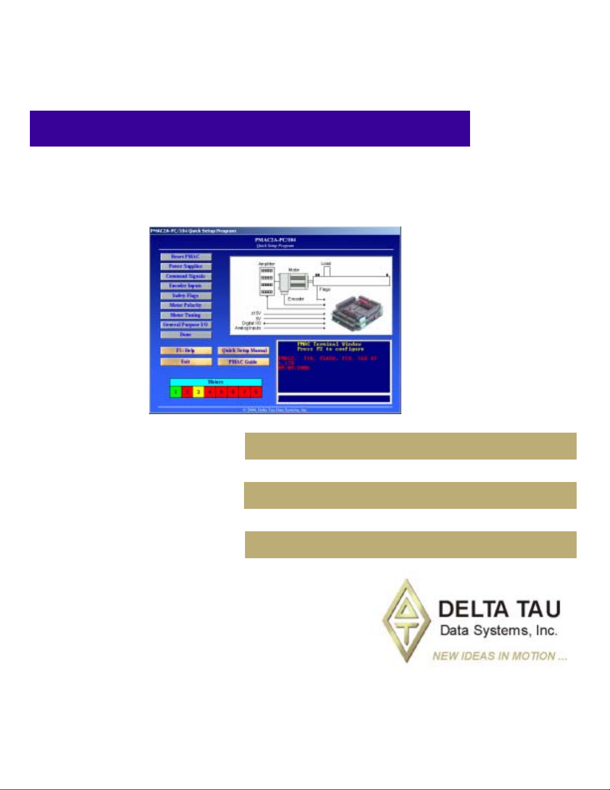
^1 EZ SETUP SOFTWARE MANUAL
^2 PMAC2A-PC/104
^3 EZ PMAC2A-PC104 Setup Manual
^4 4EZ-603670-xSxx
^5 September 24, 2004
Single Source Machine Control Power // Flexibility // Ease of Use
21314 Lassen Street Chatsworth, CA 91311 // Tel. (818) 998-2095 Fax. (818) 998-7807 // www.deltatau.com

Copyright Information
© 2003 Delta Tau Data Systems, Inc. All rights reserved.
This document is furnished for the customers of Delta Tau Data Systems, Inc. Other
uses are unauthorized without written permission of Delta Tau Data Systems, Inc.
Information contained in this manual may be updated from time-to-time due to product
improvements, etc., and may not conform in every respect to former issues.
To report errors or inconsistencies, call or email:
Delta Tau Data Systems, Inc. Technical Support
Phone: (818) 717-5656
Fax: (818) 998-7807
Email: support@deltatau.com
Website: http://www.deltatau.com
Operating Conditions
All Delta Tau Data Systems, Inc. motion controller products, accessories, and
amplifiers contain static sensitive components that can be damaged by incorrect
handling. When installing or handling Delta Tau Data Systems, Inc. products, avoid
contact with highly insulated materials. Only qualified personnel should be allowed to
handle this equipment.
In the case of industrial applications, we expect our products to be protected from
hazardous or conductive materials and/or environments that could cause harm to the
controller by damaging components or causing electrical shorts. When our products
are used in an industrial environment, install them into an industrial electrical cabinet
or industrial PC to protect them from excessive or corrosive moisture, abnormal
ambient temperatures, and conductive materials. If Delta Tau Data Systems, Inc.
products are directly exposed to hazardous or conductive materials and/or
environments, we cannot guarantee their operation.

EZ PMAC2A-PC-104 Setup Manual
Table of Contents
INTRODUCTION.......................................................................................................................................................1
Configuring PMAC...................................................................................................................................................1
Getting More Information.........................................................................................................................................1
CONNECTIONS AND INITIAL SETTINGS..........................................................................................................5
Power Supplies Connections.....................................................................................................................................5
Communication Ports Connections...........................................................................................................................5
Serial Communication Connections..........................................................................................................................5
Installing and Running the Software.........................................................................................................................6
Establishing Communications..............................................................................................................................6
If Communications Cannot be Established...........................................................................................................7
Main Setup Screen ....................................................................................................................................................7
Built-in Catalog of Functions...............................................................................................................................8
The PMAC Guide Manual ....................................................................................................................................8
Resetting PMAC for First Time Use.....................................................................................................................8
Power Supplies..........................................................................................................................................................9
Analog Amplifier Command Signals........................................................................................................................9
Stepper Driver Command Signals...........................................................................................................................10
Encoder Feedback...................................................................................................................................................11
Safety Flags: End-of-Travel Limits, Home and Amplifier Fault Inputs..................................................................12
Polarity Test............................................................................................................................................................13
TUNING THE MOTORS.........................................................................................................................................15
The Tuning Procedure.............................................................................................................................................15
The Parabolic Move ...........................................................................................................................................15
MOTOR JOG COMMANDS...................................................................................................................................17
Motor Safety I-Variables.........................................................................................................................................17
Ix11 - Motor x Fatal Following Error Limit.......................................................................................................17
Ix12 - Motor x Warning Following Error Limit.................................................................................................17
Ix13 - Motor x + Software Position Limit...........................................................................................................17
Ix14 - Motor x - Software Position Limit............................................................................................................17
Ix15 - Motor x Abort/Lim Deceleration Rate...................................................................................................... 18
Ix16 - Motor x Maximum Velocity......................................................................................................................18
Ix17 - Motor x Maximum Acceleration...............................................................................................................18
Ix19 - Motor x Maximum Jog/Home Acceleration..............................................................................................18
S-Curve and Linear Acceleration Variables.......................................................................................................18
Rate vs Time: Programming the Maximum Acceleration Parameters................................................................19
Benefits of Using S-Curve Acceleration Profiles................................................................................................19
Motor Jog Movement I-Variables...........................................................................................................................19
Ix20 Motor x Jog/Home Acceleration Time........................................................................................................19
Ix21 Motor x Jog/Home S-Curve Time...............................................................................................................19
Ix22 Motor x Jog Speed......................................................................................................................................19
Motor Jog Commands.............................................................................................................................................20
HomeZ ................................................................................................................................................................20
Jog Neg...............................................................................................................................................................20
Stop.....................................................................................................................................................................20
Jog Pos ...............................................................................................................................................................20
Jog Abs ...............................................................................................................................................................20
Jog Inc ................................................................................................................................................................ 20
HOME PROCEDURE..............................................................................................................................................21
Motor Home Movement I-Variables.......................................................................................................................21
Ix19 - Motor x Maximum Jog/Home Acceleration..............................................................................................21
Ix20 Motor x Jog/Home Acceleration Time........................................................................................................21
Table of Contents i

EZ PMAC2A-PC-104 Setup Manual
Ix21 Motor x Jog/Home S-Curve Time...............................................................................................................21
Ix23 Motor x Home Speed and Direction...........................................................................................................22
Ix26 Motor x Home Offset ..................................................................................................................................22
Motor Home Commands.........................................................................................................................................22
MOTION PROGRAMS............................................................................................................................................23
Coordinate Systems Definitions..............................................................................................................................23
S-Curve and Linear Acceleration Variables.......................................................................................................23
Benefits of Using S-Curve Acceleration Profiles................................................................................................24
Motion Program Velocity...................................................................................................................................24
Blending Disable/Enable....................................................................................................................................25
Motion Programs.....................................................................................................................................................25
PLC PROGRAMS.....................................................................................................................................................27
General-Purpose I/O and Analog Inputs Page...................................................................................................28
Software Setup........................................................................................................................................................28
General-Purpose Digital Inputs and Outputs.....................................................................................................28
Analog Inputs......................................................................................................................................................29
BACKUP AND RESET PROCEDURES................................................................................................................31
Backup Procedures..................................................................................................................................................31
Reset Procedures.....................................................................................................................................................31
Reset PMAC to Last Saved Backup File Parameters..........................................................................................32
Reset PMAC to Last Memory Saved Parameters................................................................................................32
Reset PMAC to Factory Defaults........................................................................................................................32
Save Parameters in PMAC Memory...................................................................................................................32
THE TERMINAL WINDOW AND UTILITY FUNCTIONS...............................................................................33
The Watch Window ................................................................................................................................................33
The Calculator Function ..........................................................................................................................................33
The Circle Function.................................................................................................................................................34
ii Table of Contents

EZ PMAC2A-PC-104 Setup Manual
INTRODUCTION
PMAC, pronounced Pe’-MAC, stands for Programmable Multi-Axis Controller. It is a family of highperformance servo motion controllers capable of commanding up to 32 axes of motion simultaneously
with a high level of sophistication.
The PMAC2A-PC/104, member of the PMAC family, is a cost-effective 8-axis motion controller. The
PMAC2A-PC/104 can be composed of three boards in a stack configuration. The base board provides
four channels of either DAC ±10V or pulse and direction command outputs. The optional axis expansion
board provides a set of four additional servo channels and I/O ports. The optional communications board
provides extra I/O ports and either the USB or Ethernet interface for faster communications. Only one
communication port can be used at any given time.
The PMAC Quick Setup program is a software tool for setting up and troubleshooting the PMAC2APC/104 board. Each screen is dedicated to testing and setting up a particular feature of the board, thus
making the setup of the PMAC motion controller a very simple process.
©
The PMAC Quick Setup program runs in most 32-bit Microsoft
communicate through any method including serial RS-232, USB, Ethernet, and PC/104 bus.
Configuring PMAC
PMAC is shipped with all the configuration jumpers set for a typical application. These default settings
are explained in the particular sections of this manual where each feature is illustrated.
Windows operating systems, and can
Follow these steps to install and configure PMAC for a typical application:
1. Establish power supplies connections.
2. Establish communications.
3. Establish amplifier and motor connections.
4. Establish flags connections (home switches and end-of-travel switches).
5. Check motor polarity.
6. Set up motor software parameters.
7. Jog motors.
8. Home motor s.
9. Define a coordinate system. Write and run a simple motion program.
10. Save the configuration.
Getting More Information
The PMAC Quick Setup program is provided with the PMAC Guide manual which has the complete
description of each PMAC connector and software command used in a typical application. This manual
can be accessed from the main setup screen of the program.
Introduction 1
EZ PMAC2A-PC-104 Setup Manual
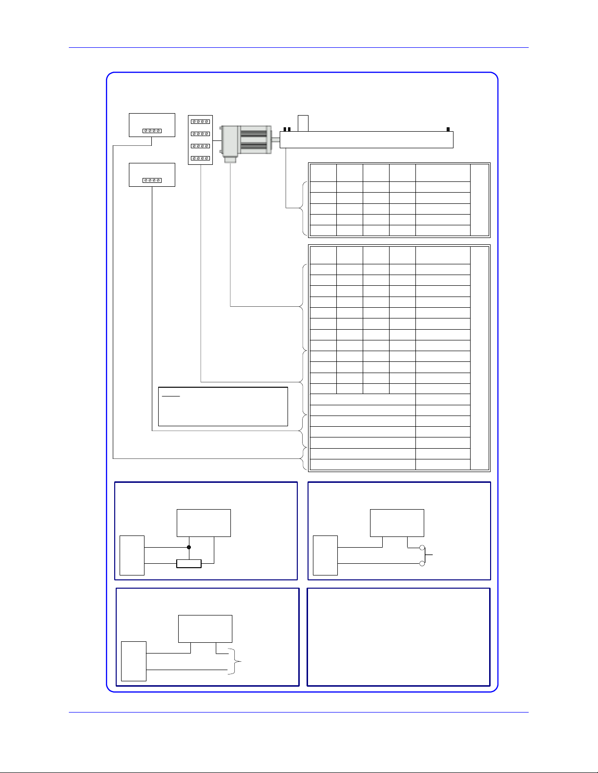
Machine Connections Example: using analog ±10 Volts amplifi ers
5V Power Supply
± 15V Power Supply
Note: The 5V and ±12V external
power supplies are only required
when PMAC is not installed in a
PC/104 computer bus.
Amplifier
Load
Motor
Flags
Motor #1
Motor #2
Motor #3
Encoder
Pin #
Pin #
5 6 19 20 HOMEn
7 8 21 22 PLIMn
9 10 23 24 MLIMn
1 1 2 2 Flag_V
3 3 4 4 Gnd
Motor #1
Motor #2
Pin #
Pin #
1 2 1 2 +5V
3 4 3 4 GND
5 6 17 18 CHAn+
7 8 19 20 CHAn-
9 10 21 22 CHBn+
11 12 23 24 CHBn13 14 25 26 CHCn+
15 16 27 28 CHCn29 30 37 38 DACn+
31 32 39 40 DACn33 34 41 42 AENAn
35 36 43 44 FAULTn
47 FLT_FLG_V
48 GND
49 +12 to +15V
50 -12 to -15V
48 GND
3 GND
1 5V
Pin #
Motor #3
Pin #
Motor #4
Pin #
Motor #4
Pin #
Symbol
Symbol
JMACH2
JMACH1
Flags Sensor Connection
5-24 VDC
JMACH2
1
7
Flag_1_2_V
PLIM1
Power Supply
+-
5 to 24 Volts normally
closed to ground NPN
sinking type sensor.
Amplifier Fault Connection
5-24 VDC
JMACH1
47
35
FLT_FLG_V
FAULT-
Power Supply
+-
Connect to
amplifier
Flags Switch Connection
5-24 VDC
JMACH2
1
7
Flag_1_2_V
PLIM1
Power Supply
+-
Normally-Closed
Switch
Software Setup
I-variables setup for using the DAC outputs:
I900 = 1001
I901 = 2
I902 = 3
I906 = 1001
I9n6 = 0 ; n = channel number from 1 to 8
Ix69 = 1024 ; x = motor number from 1 to 8
I10 = 1710933
2 Introduction
EZ PMAC2A-PC-104 Setup Manual
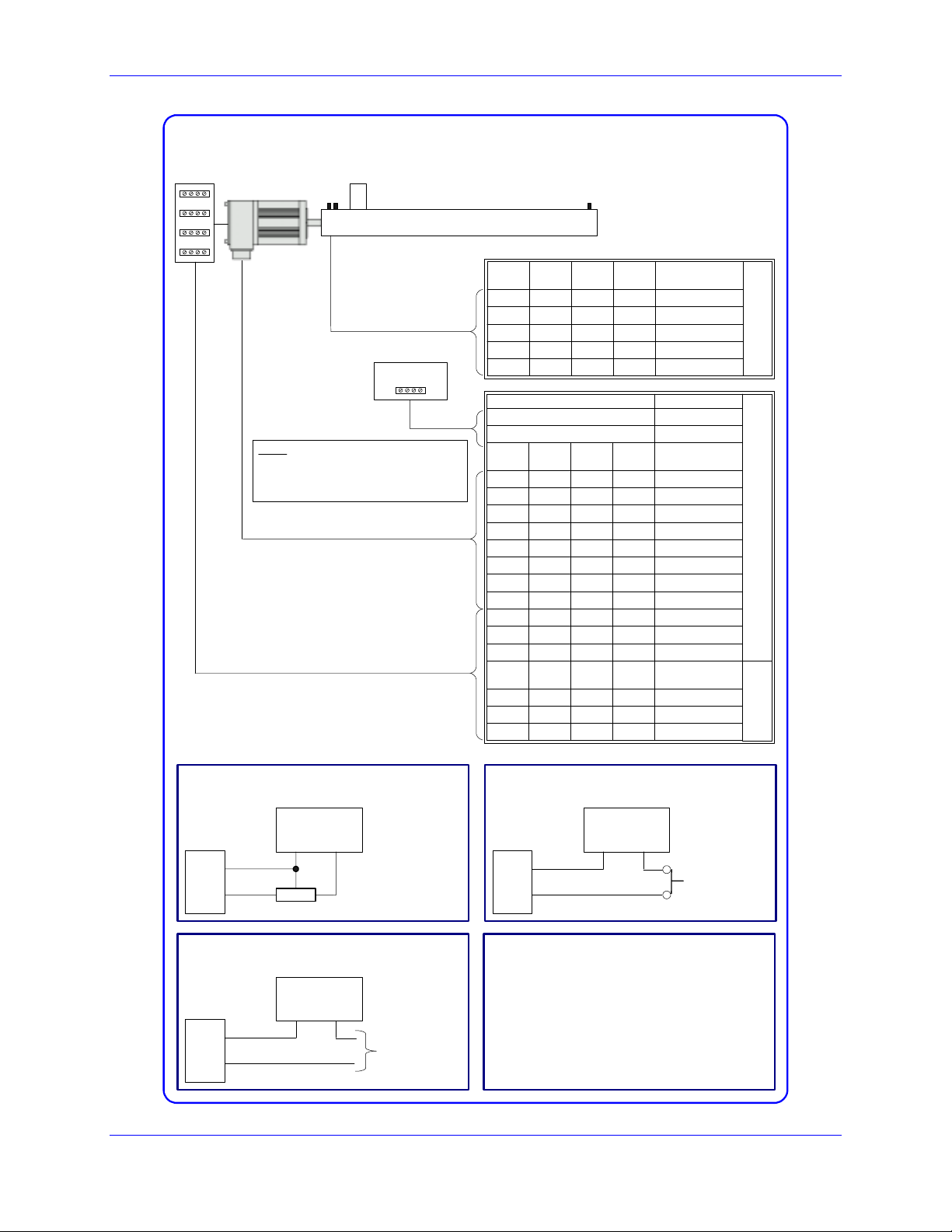
Machine Connections Example: using pulse and direction drivers
Driver
Stepper
Motor
Load
Flags
Encoder
(Optional)
5V Power Supply
Note: The 5V external power
supply is only required when
PMAC is not installed in a PC/104
computer bus.
Motor #1
Motor #2
Motor #3
Pin #
Pin #
Pin #
Motor #4
Pin #
Symbol
5 6 19 20 HOMEn
7 8 21 22 PLIMn
9 10 23 24 MLIMn
1 1 2 2 Flag_V
3 3 4 4 Gnd
Pin # Symbol
3 GND
1 5V
Motor #1
Motor #2
Motor #3
Pin #
Pin #
Pin #
Motor #4
Pin #
Symbol
1 2 1 2 +5V
3 4 3 4 GND
5 6 17 18 CHAn+
7 8 19 20 CHAn-
9 10 21 22 CHBn+
11 12 23 24 CHBn13 14 25 26 CHCn+
15 16 27 28 CHCn33 34 41 42 AENAn
35 36 43 44 FAULTn
47 47 47 47 FLT_FLG_V
Motor #1
Motor #2
Motor #3
Pin #
Pin #
Pin #
Motor #4
Pin #
Symbol
13 14 27 28 PUL_n+
15 16 29 30 DIR_n+
3 4 3 4 GND
JMACH2
JMACH1
JMACH2
Flags Sensor Connection
5-24 VDC
JMACH2
1
7
Flag_1_2_V
PLIM1
Power Supply
+-
5 to 24 Volts normally
closed to ground NPN
sinking type sensor.
Driver Fault Connection
5-24 VDC
JMACH1
47
35
FLT_FLG_V
FAULT-
Power Supply
+-
Connect to
driver
Flags Switch Connection
5-24 VDC
JMACH2
1
7
Flag_1_2_V
PLIM1
Power Supply
+-
Normally-Closed
Switch
Software Setup
I-variables setup for using the stepper outputs:
Ix02 = * ; x = motor number from 1 to 8
Ix02 = Ix02+2 ; x = motor number from 1 to 8
I9n6 = 2 ; n = channel number from 1 to 8
I-variables setup if no encoder feedback is used:
I9n0 = 8 ; n = channel number from 1 to 8
Introduction 3

EZ PMAC2A-PC-104 Setup Manual
4 Introduction
EZ PMAC2A-PC-104 Setup Manual
CONNECTIONS AND INITIAL SETTINGS
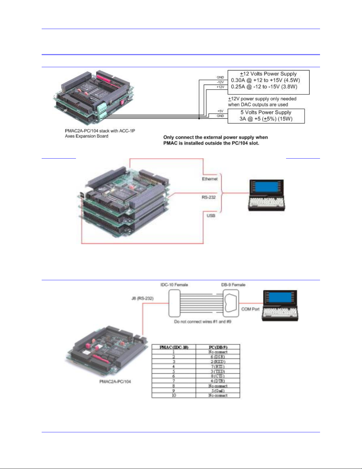
Power Supplies Connections
Communication Ports Connections
• Connect the host computer to only one communication port, either PC/104 bus, RS-232, USB or
Ethernet.
• Select the port by clicking on the Device button.
Serial Communication Connections
Connections and Initial Settings 5

EZ PMAC2A-PC-104 Setup Manual
Installing and Running the Software
Install the program by selecting the appropriate option on the CD-ROM provided or running the
executable program downloaded from the Delta Tau website, and following the instructions on the screen.
After the program is installed successfully, a new folder labeled QSPC104 will be present on the
Windows
• EZ PMAC2A-PC/104 Setup Manual opens the electronic form of this manual.
• PMAC Guide opens the electronic form of the PMAC Guide which the most complete resource of
• Setup runs the PMAC Quick Setup program for configuring and testing all motors for the first time.
• Terminal runs the PMAC Quick Setup program for programming the PMAC motion controller after
Establishing Communications
©
Start menu. The folder contains these items:
information for configuring and programming the PMAC2A-PC/104 motion controller.
all motors have been properly configured.
Once PMAC is properly powered and the communications cable has been connected between the host
computer and the PMAC, communications can be established. The communications setup screen appears
when the program is run for the first time or when the PMAC cannot be found in the previously defined
channel of communications. Press the F1 function key for instructions.
The Instructions button provides a direct link to the PCOMM32 manual and it explains how to enable
PMAC communications under different operating systems.
The program can run even if PMAC is not linked to the computer. By pressing the Offline button, the
program is run in simulated dry mode.
6 Connections and Initial Settings
EZ PMAC2A-PC-104 Setup Manual
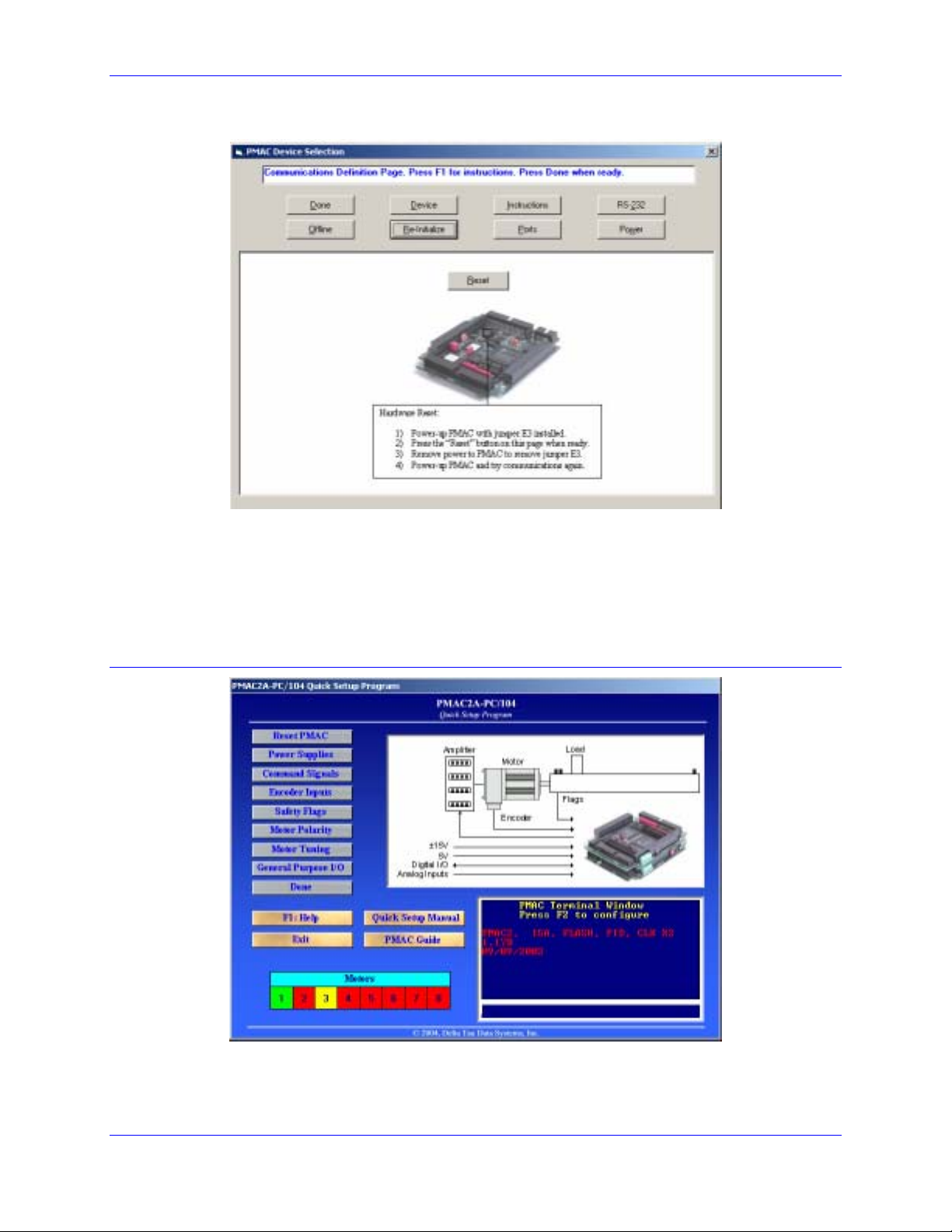
If Communications Cannot be Established
1. Press the Re-Initialize button on the Communications Setup screen.
2. Power-up PMAC with jumper E3 on the baseboard installed.
3. Make sure the green LED in PMAC is lit; this will confirm that PMAC is properly powered with 5V.
4. Press the Reset button in the middle of the screen. This will reset the memory to factory defaults.
5. Turn off PMAC and remove the E3 jumper.
6. Power-up PMAC and try communications again.
Main Setup Screen
Once communications has been established, the main Setup screen displays. At any time during the
execution of this program, press the F1 function key to get instructions for each particular page.
Connections and Initial Settings 7
EZ PMAC2A-PC-104 Setup Manual
The steps to configure PMAC are listed sequentially from top to bottom, but they can be called in any
order.
A simple terminal is provided to allow a direct communication with PMAC. However, during the initial
setup process this is seldom necessary. If any I-Variable is changed on the terminal window, or if any
reset command is issued, all motor status will change to red and the setup process must be repeated for
each required motor.
The colored motors status strip helps determine the configuration of each motor. A red-colored square
indicates that the polarity test has not yet been run for the particular motor. A yellow colored square
indicates that the motor passed the polarity test, but its servo parameters haved not yet been tuned. A
green colored square indicates that the motor has already been tuned and that it is ready to be operated in
closed-loop mode. Clicking on the particular motor box will open the appropriate screen to complete the
motor setup. For example, if the motor status is indicated with a red box, then the motor polarity test
screen will open. If the motor status is indicated with a yellow box instead, then the motor tuning screen
will open.
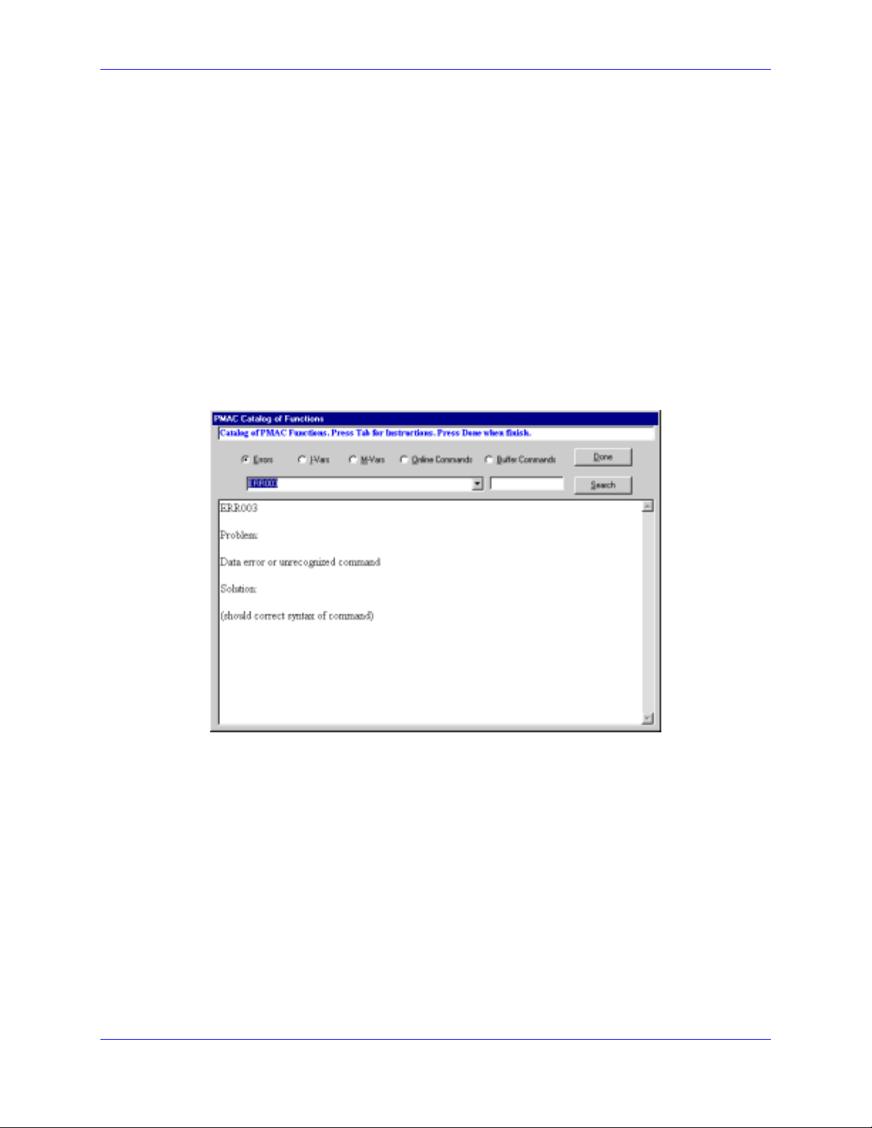
Built-in Catalog of Functions
This function, accessible from the F1 Help command, allows searching for the description of any PMAC
setup variable or command. The Search button will list all the entries based on a particular entered search
key. This window can be kept open at all times for easy reference to each command in every part of the
setup process.
The PMAC Guide Manual
This Acrobat© PDF file is the most complete reference for setting up PMAC for a typical application.
This file also can be kept open for easy reference during the setup process.
Resetting PMAC for First Time Use
The first button on the setup screen is labeled Reset and allows PMAC to be reset for first time use. This
is recommended if setting up this particular PMAC for the first time and there are no contents in its
memory that needs to be kept. After performing this procedure, all programs inside memory will be
erased and all variables will be configured to the default values.
8 Connections and Initial Settings
Loading...