

Page 1
^1 USER MANUAL
^2 Geo PMAC Drive
Single Source Machine Control Power // Flexibility // Ease of Use
21314 Lassen Street Chatsworth, CA 91311 // Tel. (818) 998-2095 Fax. (818) 998-7807 // www.deltatau.com
^3 Programmable Servo Amplifier
^4 500-603704-xUxx
^5 April 28, 2010
Page 2

Page 3

Copyright Information
© 2010 Delta Tau Data Systems, Inc. All rights reserved.
This document is furnished for the customers of Delta Tau Data Systems, Inc. Other uses are
unauthorized without written permission of Delta Tau Data Systems, Inc. Information contained
in this manual may be updated from time-to-time due to product improvements, etc., and may not
conform in every respect to former issues.
To report errors or inconsistencies, call or email:
Delta Tau Data Systems, Inc. Technical Support
Phone: (818) 717-5656
Fax: (818) 998-7807
Email: support@deltatau.com
Website: http://www.deltatau.com
Operating Conditions
All Delta Tau Data Systems, Inc. motion controller products, accessories, and amplifiers contain
static sensitive components that can be damaged by incorrect handling. When installing or
handling Delta Tau Data Systems, Inc. products, avoid contact with highly insulated materials.
Only qualified personnel should be allowed to handle this equipment.
In the case of industrial applications, we expect our products to be protected from hazardous or
conductive materials and/or environments that could cause harm to the controller by damaging
components or causing electrical shorts. When our products are used in an industrial
environment, install them into an industrial electrical cabinet or industrial PC to protect them
from excessive or corrosive moisture, abnormal ambient temperatures, and conductive materials.
If Delta Tau Data Systems, Inc. products are directly exposed to hazardous or conductive
materials and/or environments, we cannot guarantee their operation.
Safety Instructions
Qualified personnel must transport, assemble, install, and maintain this equipment. Properly
qualified personnel are persons who are familiar with the transport, assembly, installation, and
operation of equipment. The qualified personnel must know and observe the following standards
and regulations:
IEC 364 resp. CENELEC HD 384 or DIN VDE 0100
IEC report 664 or DIN VDE 0110
National regulations for safety and accident prevention or VBG 4
Incorrect handling of products can result in injury and damage to persons and machinery. Strictly
adhere to the installation instructions. Electrical safety is provided through a low-resistance earth
connection. It is vital to ensure that all system components are connected to earth ground.
This product contains components that are sensitive to static electricity and can be damaged by
incorrect handling. Avoid contact with high insulating materials (artificial fabrics, plastic film,
etc.). Place the product on a conductive surface. Discharge any possible static electricity build-up
by touching an unpainted, metal, grounded surface before touching the equipment.
Keep all covers and cabinet doors shut during operation. Be aware that during operation, the
product has electrically charged components and hot surfaces. Control and power cables can
carry a high voltage, even when the motor is not rotating. Never disconnect or connect the
product while the power source is energized to avoid electric arcing.
Page 4

After removing the power source from the equipment, wait at least 10 minutes before touching or
disconnecting sections of the equipment that normally carry electrical charges (e.g., capacitors,
contacts, screw connections). To be safe, measure the electrical contact points with a meter before
touching the equipment.
The following text formats are used in this manual to indicate a potential for personal injury or
equipment damage. Read the safety notices in this manual before attempting installation,
operation, or maintenance to avoid serious bodily injury, damage to the equipment, or operational
difficulty.
WARNING:
A Warning identifies hazards that could result in personal injury or death.
It precedes the discussion of interest.
Caution:
A Caution identifies hazards that could result in equipment damage. It
precedes the discussion of interest
Note:
A Note identifies information critical to the user’s understanding or use of
the equipment. It follows the discussion of interest.
Page 5

REVISION HISTORY
REV. DESCRIPTION DATE CHG APPVD
1 ADDED SAFETY RELAY PN INFO, P. 38 04/28/10 CP S.MILICI
Page 6

Page 7

Geo PMAC Drive User Manual
Table of Contents
Copyright Information................................................................................................................................................i
Operating Conditions .................................................................................................................................................i
Safety Instructions......................................................................................................................................................i
INTRODUCTION .......................................................................................................................................................1
User Interface ............................................................................................................................................................1
Geo MACRO Drives .............................................................................................................................................1
Geo Direct-PWM Drives ......................................................................................................................................1
Geo PMAC Drives ................................................................................................................................................2
Feedback Devices......................................................................................................................................................3
Compatible Motors....................................................................................................................................................3
Maximum Speed....................................................................................................................................................3
Torque...................................................................................................................................................................4
Motor Poles ..........................................................................................................................................................4
Motor Inductance..................................................................................................................................................5
Motor Resistance ..................................................................................................................................................5
Motor Back EMF ..................................................................................................................................................5
Motor Torque Constant ........................................................................................................................................5
Motor Inertia ........................................................................................................................................................5
Motor Cabling ......................................................................................................................................................5
SPECIFICATIONS .....................................................................................................................................................7
Part Number ..............................................................................................................................................................7
Geo PMAC Feedback Options..................................................................................................................................8
Package Types...........................................................................................................................................................8
Electrical Specifications............................................................................................................................................9
240VAC Input Drives............................................................................................................................................9
480VAC Input Drives..........................................................................................................................................11
Environmental Specifications..................................................................................................................................13
Recommended Fusing and Wire Gauge..................................................................................................................13
RECEIVING AND UNPACKING...........................................................................................................................15
Use of Equipment....................................................................................................................................................15
MOUNTING ..............................................................................................................................................................17
Low Profile .........................................................................................................................................................18
Single Width........................................................................................................................................................19
Double Width......................................................................................................................................................20
CONNECTIONS .......................................................................................................................................................21
System (Power) Wiring...........................................................................................................................................21
Wiring AC Input, J1 ................................................................................................................................................23
Wiring Earth-Ground ..............................................................................................................................................23
Wiring 24 V Logic Control, J4................................................................................................................................24
Wiring the Motors ...................................................................................................................................................24
J2: Motor 1 Output Connector Pinout...............................................................................................................24
J3: Motor 2 Output Connector Pinout (Optional).............................................................................................24
Wiring the Motor Thermostats................................................................................................................................25
Wiring the Regen (Shunt) Resistor J5.....................................................................................................................25
J5: External Shunt Connector Pinout................................................................................................................26
Shunt Regulation.................................................................................................................................................27
Minimum Resistance Value.................................................................................................................................27
Maximum Resistance Value................................................................................................................................27
Energy Transfer Equations.................................................................................................................................27
Bonding...................................................................................................................................................................30
Filtering...................................................................................................................................................................30
CE Filtering........................................................................................................................................................30
Table of Contents i
Page 8

Geo PMAC Drive User Manual
Input Power Filtering .........................................................................................................................................30
Motor Line Filtering...........................................................................................................................................31
I/O Filtering........................................................................................................................................................31
CONNECTORS.........................................................................................................................................................33
Connector Pinouts ...................................................................................................................................................33
X1: Encoder Input 1...........................................................................................................................................33
X2: Encoder Input 2...........................................................................................................................................34
X3: General Purpose I/O...................................................................................................................................35
X4: Safety Relay (Optional)...............................................................................................................................38
X5: USB 2.0 Connector .....................................................................................................................................38
X6: RJ45, Ethernet Connector...........................................................................................................................38
X7: Analog I/O (Optional, Option 3/4/5)...........................................................................................................39
X8: S. Encoder 1................................................................................................................................................39
X9: S. Encoder 2................................................................................................................................................41
X10: Discrete I/O...............................................................................................................................................42
J1: AC Input Connector Pinout .........................................................................................................................45
J2: Motor 1 Output Connector Pinout...............................................................................................................45
J3: Motor 2 Output Connector Pinout (Optional).............................................................................................45
J4: 24VDC Input Logic Supply Connector ........................................................................................................45
J5: External Shunt Connector Pinout................................................................................................................45
SETTING UP THE ENCODERS.............................................................................................................................46
Setting up Quadrature Encoders..............................................................................................................................46
Signal Format .....................................................................................................................................................46
Hardware Setup..................................................................................................................................................46
Setting up SSI Encoders..........................................................................................................................................47
Hardware Setup..................................................................................................................................................47
Software Setup ....................................................................................................................................................48
Setting up Sinusoidal Encoders...............................................................................................................................52
Encoder Connections..........................................................................................................................................52
Hardware Setup..................................................................................................................................................52
Software Setup ....................................................................................................................................................53
Principle of Operation........................................................................................................................................54
Setting up EnDat Interface ......................................................................................................................................56
Hardware Setup..................................................................................................................................................56
Software Setup ....................................................................................................................................................57
Ix10 Setup for Geo PMAC drive in use with EnDat............................................................................................57
Ix81 Setup for Geo PMAC drive in use with EnDat............................................................................................57
Setting up Resolvers................................................................................................................................................59
Hardware Setup..................................................................................................................................................59
Software Setup ....................................................................................................................................................60
I1010 Resolver Excitation Phase Offset ......................................................................................................61
I1011 Resolver Excitation Gain...................................................................................................................61
I1012 Resolver Excitation Frequency Divider ............................................................................................61
Setting Up Digital Hall Sensors ..............................................................................................................................62
Signal Format .....................................................................................................................................................62
Hardware Setup..................................................................................................................................................62
Using Hall Effect Sensors for Phase Reference..................................................................................................63
Determining the Commutation Phase Angle.......................................................................................................63
Finding the Hall Effect Transition Points...........................................................................................................64
Calculating the Hall Effect Zero Point (HEZ)....................................................................................................64
Determining the Polarity of the Hall Effects – Standard or Reversed................................................................67
Software Settings for Hall Effect Phasing...........................................................................................................67
Optimizing the Hall Effect Phasing Routine for Maximum Performance...........................................................68
Encoder Loss Setup.................................................................................................................................................73
Program Accessible Amplifier Status Codes...........................................................................................................75
ii Table of Contents
Page 9

Geo PMAC Drive User Manual
DIRECT PWM COMMUTATION CONTROLLER SETUP ..............................................................................76
Key Servo IC Variables...........................................................................................................................................76
Key Motor Variables...............................................................................................................................................76
DC BRUSH MOTOR DRIVE SETUP.....................................................................................................................78
I-Variable Setup ......................................................................................................................................................78
Hardware Connection..............................................................................................................................................79
SETTING I2T PROTECTION .................................................................................................................................80
CALCULATING MINIMUM PWM FREQUENCY.............................................................................................82
TROUBLESHOOTING............................................................................................................................................85
Error Codes .............................................................................................................................................................85
D1: AMP Status Display Codes..........................................................................................................................85
7-segment LED ...................................................................................................................................................85
Status LEDs.............................................................................................................................................................86
APPENDIX A.............................................................................................................................................................87
Mating Connector and Cable Kits...........................................................................................................................87
Mating Connector and Cable Kits...........................................................................................................................87
Mating Connector and Cable Kits......................................................................................................................87
Connector and Pins Part Numbers.....................................................................................................................88
Cable Drawings.......................................................................................................................................................90
Regenerative Resistor: GAR78/48 .........................................................................................................................96
Type of Cable for Encoder Wiring..........................................................................................................................97
APPENDIX B.............................................................................................................................................................99
Schematics...............................................................................................................................................................99
X8 and X9 S.Encoder..........................................................................................................................................99
X3: General Purpose IO.....................................................................................................................................99
X10: Limits for Axis 1 and 2 .............................................................................................................................100
APPENDIX C...........................................................................................................................................................101
SUGGESTED M-VARIABLE DEFINITIONS....................................................................................................101
MEMORY AND I/O MAP ADDENDUM.............................................................................................................107
Table of Contents iii
Page 10

Page 11

Geo PMAC Drive User Manual
INTRODUCTION
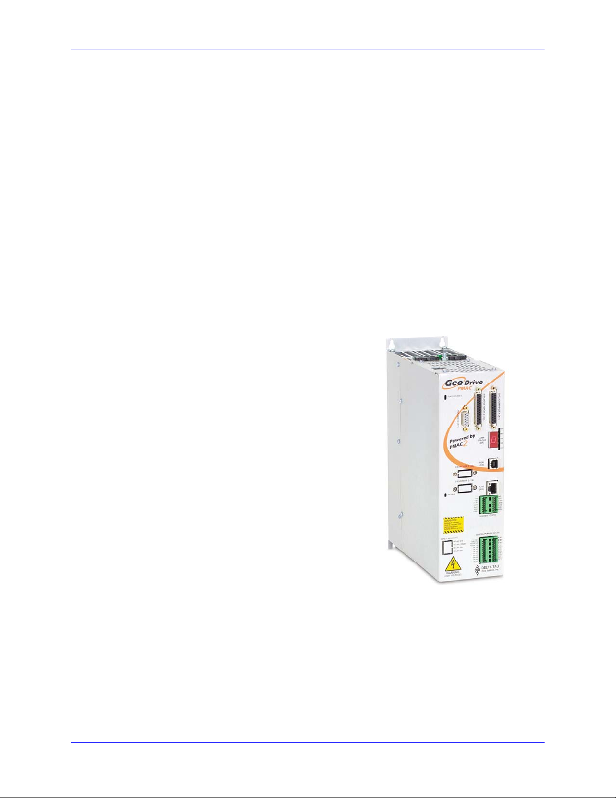
The Geo Drive family of “bookcase”-style servo amplifiers provides many new capabilities for users.
This family of 1- and 2-axis 3-phase amplifiers, built around a common core of highly integrated IGBTbased power circuitry, supports a wide variety of motors, power ranges, and interfaces. The 2-axis
configurations share common power input, bus, and shunt for a very economical implementation.
Three command interfaces are provided: direct-PWM, MACRO-ring, and integrated PMAC controller,
each described in following sections. In all three cases, fully digital “direct PWM” control is used. Direct
PWM control eliminates D-to-A and A-to-D conversion delays and noise, allowing higher gains for more
robust and responsive tuning without sacrificing stability.
All configurations provide these power-stage features:
• Direct operation off AC power mains (100 – 240 or 300 – 480 VAC, 50/60 Hz) or optional DC
power input (24 – 350 or 24 – 700 VDC)
• Integrated bus power supply including soft start and shunt regulator (external resistor required)
• Separate 24VDC input to power logic circuitry
• Complete protection: over voltage, under voltage, over temperature, PWM frequency limit,
minimum dead time, motor over temperature, short circuit, over current, input line monitor
• Ability to drive brushed and brushless permanent-magnet servo motors, or AC induction motors
• Single-digit LED display and six discrete LEDs for status information
• Optional safety relay circuitry. Please contact factory for more details and pricing.
• Easy setup with Turbo PMAC and UMAC controllers.
User Interface
The Geo Drive family is available in different versions distinguished by their user interface styles.
Geo MACRO Drives
The Geo MACRO Drive interfaces to the controller through the 125 Mbit/sec MACRO ring, with
either a fiber-optic or Ethernet electrical medium, accepting numerical command values for direct
PWM voltages and returning numerical feedback values for phase current, motor position, and status.
It accepts many types of position feedback to the master controller, as well as axis flags (limits, home,
and user) and general-purpose analog and digital I/O. Typically, the Geo MACRO Drives are
commanded by either a PMAC2 Ultralite bus-expansion board, or a UMAC rack-mounted controller
with a MACRO-interface card. This provides a highly distributed hardware solution, greatly
simplifying system wiring, while maintaining a highly centralized software solution, keeping system
programming simple.
• Choices for main feedback for each axis: A/B quadrature encoder, sinusoidal encoder with
• Secondary A/B quadrature encoder for each axis
EnDat
TM
or HiperfaceTM, SSI encoder, resolver
• General-purpose isolated digital I/O: 4 in, 4 out at 24VDC
• 2 optional A/D converters, 12- or 16-bit resolution
Geo Direct-PWM Drives
The direct-PWM interface versions accept the actual power-transistor on/off signals from the PMAC2
controller, while providing digital phase-current feedback and drive status to the controller for closed-
Introduction 1
Page 12
Geo PMAC Drive User Manual
loop operation. Interface to the direct-PWM amplifier is through a standard 36-pin Mini-D style
cable. The drive performs no control functions but has protection features. Drive installation,
maintenance, and replacement are simplified because there is less wiring (position feedback and I/O
are not connected to the drive) and there are no variables to set or programs to install in the drive.
• Fully centralized control means that all gains and settings are made in the PMAC; no software
setup of drive is required
• No position feedback or axis flags required at the drive
Geo PMAC Drives
The Geo PMAC Drive is a standalone-capable integrated controller/amplifier with a built-in full
PMAC2 controller having stored-program capability. It can be operated standalone, or commanded
from a host computer through USB2.0 or 100 Mbps Ethernet ports. The controller has the full
software capabilities of a PMAC (see descriptions), with an internal fully-digital connection to the
advanced Geo power-stage , providing a convenient, compact, and cost-effective installation for one
and two-axis systems, with easy synchronization to other drives and controls.
• Choices for main feedback for each axis: A/B quadrature encoder, sinusoidal encoder with
• Secondary A/B quadrature encoder for each axis
• General-purpose isolated digital I/O: 8 in, 6 out at 24VDC
• 2 optional A/D converters 12- or 16-bit resolution
EnDat
TM
or HiperfaceTM, SSI encoder, resolver
Motion Controller Standard Features:
• Motorola DSP 56k digital signal processor
• PMAC2 CPU
• Fully Configurable via USB2.0 and Ethernet TCP/IP
• Operation from a PC via setup software
• Stand-alone operation
• Linear and circular interpolation
• 256 motion programs capacity
• 64 asynchronous PLC program capability
• Rotating buffer for large programs
• 36-bit position range (± 64 billion counts)
• Adjustable S-curve acceleration and deceleration
• Cubic trajectory calculations, splines
• Set and change parameters in real time
• Torque, Velocity and Position control standard
• Full rated temperature cooling standard (no need for additional fans except small power models)
• Eight inputs @12-24V, fully-protected and isolated with separate commons for two banks of four.
• Six thermal-fuse protected outputs rated for 0.5A @, 24VDC each. (Flexible outputs allow for sinking
or sourcing of current depending on whether the common emitter or common collector is used.)
• On single axis drives: One primary encoder with TTL differential/single-ended inputs with A, B
quadrature channels and C index channel, 10 MHz cycle rate, or SSI feedback and Hall-effect inputs.
Plus one secondary encoder with TTL differential/single-ended input with A, B quadrature feedback
2 Introduction
Page 13

Geo PMAC Drive User Manual
• On two axis drives: Two primary encoders with TTL differential/single-ended inputs with A, B
quadrature channels and C index channel, 10 MHz cycle rate, or SSI feedback and Hall-effect inputs,
plus two secondary encoders with TTL differential/single-ended input with A, B quadrature feedback
for Axis 1 and 2.
• Four flags per axis: HOME, PLIM, MLIM, and USER inputs; EQU compare output per axis.
Amplifier Standard Features:
• Direct Line Connections: models for either 240VAC or 480VAC, single or three phases
• DC operation from 24VDC to 740VDC
• Designed for UL and CE Certification (approval pending)
• Small footprint saves space.
• Dual-axis configurations are more economical and save panel space and installation wiring
• Complete protection: over voltage, under voltage, over temperature, motor over temperature, short
circuit, over current, motor over temperature, input phase loss detection, shunt over-current detection.
• Integrated bus power supply including shunt regulator (external resistor required)
• Full ratings to 45°C ambient.
Optional Features:
• Resolvers or sine/cosine interpolator with Options 1 or 4
• Absolute encoder Inputs, Endat, Hiperface, SSI, with Options 2 or 5
• Two 16-bit analog-to-digital converter inputs, +/-10VDC, included with Options 3, 4 or 5.
• One differential 12-bit filtered PWM analog output, +/- 10V, included with Options 3, 4 or 5.
• Modbus Ethernet Connection, with Option M, special firmware.
Feedback Devices
Many motors incorporate a position feedback device. Devices are incremental encoders, resolvers, and
sine encoder systems. The PMAC2 version of the Geo drive accepts feedback. In its standard form, it is
set up to accept incremental encoder feedback and SSI encoders (one at a time). With the appropriate
option, it is possible to use either resolver or sinusoidal encoder feedback. Historically, the choice of a
feedback device has been guided largely by cost and robustness. Today, feedbacks are relatively constant
for the cost and picked by features such as size and feedback data. More feedback data or resolution
provides the opportunity to have higher gains in a servo system.
Geo PMAC drives have standard Secondary quadrature encoder feedback. One secondary encoder (X8)
for one axis Drive and two secondary encoders (X8 and X9) for dual axis Drives.
Compatible Motors
The Geo drive product line is capable of interfacing to a wide variety of motors. The Geo drive can
control almost any type of three-phase brushless motor, including DC brushless rotary, AC brushless
rotary, induction, and brushless linear motors. Permanent magnet DC brush motors can also be controlled
using two of the amplifiers three phases. Motor selection for an application is a science in itself and
cannot be covered in this manual. However, some basic considerations and guidelines are offered. Motor
manufacturers include a host of parameters to describe their motor.
Some basic equations can help guide an applications engineer to mate a proper drive with a motor. A
typical application accelerates a load to a speed, running the speed for a while and then decelerating the
load back into position.
Maximum Speed
The motor’s maximum rated speed is given. This speed may or may not be achievable in a given system.
The speed could be achieved if enough voltage and enough current loop gain are available. In addition,
consider the motor’s feedback adding limitations to achievable speeds. The load attached to the motor
Introduction 3
Page 14

Geo PMAC Drive User Manual
also limits the maximum achievable speed. In addition, some manufacturers will provide motor data with
their drive controller, which is tweaked to extend the operation range that other controllers may be able to
provide. In general, the maximum speed can be determined by input voltage line-to-line divided by Kb
(the motor’s back EMF constant). It is wise to de-rate this a little for proper servo applications.
Torque
The torque required for the application can be viewed as both instantaneous and average. Typically, the
instantaneous or peak torque is calculated as a sum of machining forces or frictional forces plus the forces
required to accelerate the load inertia. The machining or frictional forces on a machine must be
determined by the actual application. The energy required to accelerate the inertia follows the equation:
T = JA, where T is the torque in Newton-meters or pound-feet required for the acceleration, J is the inertia
in kilogram-meters-squared or pound-feet-second squared, and A is in radians per second per second.
The required torque can be calculated if the desired acceleration rate and the load inertia reflected back to
the motor are known. The T=JA equation requires that the motor's inertia be considered as part of the
inertia-requiring torque to accelerate.
Once the torque is determined, the motor’s specification sheet can be reviewed for its torque constant
parameter (Kt). The torque required at the application divided by the Kt of the motor provides the peak
current required by the amplifier. A little extra room should be given to this parameter to allow for good
servo control.
Most applications have a duty cycle in which the acceleration profile occurs repetitively over time.
Calculating the average value of this profile gives the continuous rating required by the amplifier.
Applications also concern themselves with the ability to achieve a speed. The requirements can be
reviewed by either defining what the input voltage is to the drive, or defining what the voltage
requirements are at the motor. Typically, a system is designed at a 230 or 480V input line. The motor
must be able to achieve the desired speed with this voltage limitation. This can be determined by using
the voltage constant of the motor (Kb), usually specified in volts-per-thousand rpm. The application
speed is divided by 1000 and multiplied by the motor's Kb. This is the required voltage to drive the motor
to the desired velocity. Headroom of 20% is suggested to allow for good servo control.
Peak Torque
The peak torque rating of a motor is the maximum achievable output torque. It requires that the amplifier
driving it be able to output enough current to achieve this. Many drive systems offer a 3:1 peak-tocontinuous rating on the motor, while the amplifier has a 2:1 rating. To achieve the peak torque, the drive
must be sized to be able to deliver the current to the motor. The required current is often stated on the
datasheet as the peak current through the motor. In some sense, it can also be determined by dividing the
peak amplifier's output rating by the motor's torque constant (Kt).
Continuous Torque
The continuous torque rating of the motor is defined by a thermal limit. If more torque is consumed from
the motor than this on average, the motor overheats. Again, the continuous torque output of the motor is
subject to the drive amplifier’s ability to deliver that current. The current is determined by the
manufacturer’s datasheets stating the continuous RMS current rating of the motor and can also be
determined by using the motor's Kt parameter, usually specified in torque output per amp of input current.
Motor Poles
Usually, the number of poles in the motor is not a concern to the actual application. However, it should
be noted that each pole-pair of the motor requires an electrical cycle. High-speed motors with high motor
pole counts can require high fundamental drive frequencies that a drive amplifier may or may not be able
to output. In general, drive manufacturers with PWM switching frequencies (16kHz or below) would like
to see commutation frequencies less than 400 Hz. The commutation frequency is directly related to the
4 Introduction
Page 15

Geo PMAC Drive User Manual
number of poles in the motor.
Motor Inductance
PWM outputs require significant motor inductance to turn the on-off voltage signals into relatively
smooth current flow with small ripple. Typically, motor inductance of servomotors is 1 to 15 mH. The
Geo drive product series can drive this range easily. On lower-inductance motors (below 1mH), problems
occur due to PWM switching where large ripple currents flow through the motor, causing excessive
energy waste and heating. If an application requires a motor of less than 1mH, external inductors are
recommended to increase that inductance. Motors with inductance in excess of 15mH can still be driven,
but are slow to react and typically are out of the range of high performance servomotors.
Motor Resistance
Motor resistance is not really a factor in determining the drive performance, but rather, comes into play
more with the achievable torque or output horsepower from the motor. The basic resistance shows up in
the manufacturer's motor horsepower curve.
Motor Back EMF
The back EMF of the motor is the voltage that it generates as it rotates. This voltage subtracts from the
bus voltage of the drive and reduces the ability to push current through the motor. Typical back EMF
ratings for servomotors are in the area of 8 to 200 volts-per-thousand rpm. The Geo drive product series
can drive any range of back EMF motor, but the back EMF is highly related to the other parameters of the
motor such as the motor inductance and the motor Kt. It is the back EMF of the motor that limits the
maximum achievable speed and the maximum horsepower capability of the motor.
Motor Torque Constant
Motor torque constant is referred to as Kt and usually it is specified in torque-per-amp. It is this number
that is most important for motor sizing. When the load that the motor will see and knowing the motor’s
torque constant is known, the drive amplifier requirements can be calculated to effectively size a drive
amplifier for a given motor. Some motor designs allow Kt to be non-linear, in which Kt will actually
produce less torque per unit of current at higher output speeds. It is wise to de-rate the systems torque
producing capability by 20% to allow headroom for servo control.
Motor Inertia
Motor inertia comes into play with motor sizing because torque to accelerate the inertia of the motor is
effectively wasted energy. Low inertia motors allow for quicker acceleration. However, consider the
reflected inertia from the load back to the motor shaft when choosing the motor’s inertia. A high ratio of
load-to-motor inertia can limit the achievable gains in an application if there is compliance in the
transmission system such as belt-drive systems or rubber-based couplings to the systems. The closer the
rotor inertia matches the load’s reflected inertia to the motor shaft, the higher the achievable gains will be
for a given system. In general, the higher the motor inertia, the more stable the system will be inherently.
Mechanical gearing is often placed between the load and the motor simply to reduce the reflected inertia
back to the motor shaft.
Motor Cabling
Motor cables are an integral part of a motor drive system. Several factors should be considered when
selecting motor cables. First, the PWM frequency of the drive emits electrical noise. Motor cables must
have a good-quality shield around them. The motor frame must also have a separate conductor to bring
back to the drive amplifier to help quench current flows from the motor due to the PWM switching noise.
Both motor drain wire and the cable shield should be tied at both ends to the motor and to the drive
amplifier.
Another consideration in selecting motor cables is the conductor-to-conductor capacitance rating of the
cable. Small capacitance is desirable. Longer runs of motor cable can add motor capacitance loading to
Introduction 5
Page 16

Geo PMAC Drive User Manual
the drive amplifier causing undesired spikes of current. It can also cause couplings of the PWM noise
into the earth grounds, causing excessive noise as well. Typical motor cable ratings would be 50 pf per
foot maximum cable capacitance.
Another factor in picking motor cables is the actual conductor cross-sectional area. This refers to the
conductor’s ability to carry the required current to and from the motor. When calculating the required
cable dimensions, consider agency requirements, safety requirements, maximum temperature that the
cable will be exposed to, the continuous current flow through the motor, and the peak current flow
through the motor. Typically, it is not suggested that any motor cable be less than 14 AWG.
The motor cable’s length must be considered as part of the application. Motor cable length affects the
system in two ways. First, additional length results in additional capacitive loading to the drive. The
drive’s capacitive loading should be kept to no more than 1000pf. Additionally, the length sets up
standing waves in the cable, which can cause excessive voltage at the motor terminals. Typical motor
cable length runs up to 60 meters (200 feet) for 230V systems and 15 meters (50 feet) for 480V systems
are acceptable. Exceeding these lengths may put other system requirements in place for either a snubber
at the motor end or a series inductor at the drive end. The series inductor at the drive end provides
capacitance loading isolation from the drive and slows the rise time of the PWM signal into the cable,
resulting in less voltage overshoot at the motor.
6 Introduction
Page 17
Geo PMAC Drive User Manual
SPECIFICATIONS
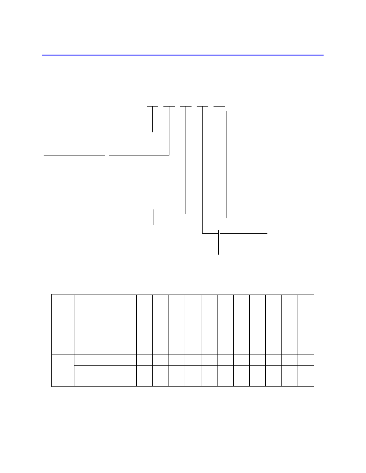
Part Number
Geo PMAC Drive
Model Number Definition
GIL03 01 0
Voltage Rating (Direct M ains )
L = 110 - 240 VAC
H = 300 - 480 VAC
Continuous/Peak Current Rating
(Sinusoidal RMS)
01 = 1.5/4.5 Amp (single or 3
03 = 3/9 Amp (single or 3
05 = 5/10 Amp (3
10 = 10/20 Amp (3
15 = 15/30 Amp (3
20 = 20/40 Amp (3
30 = 30/60 Amp (3
*For single phase input, need to derate 30%
Product Width According to Ratings
Single-Width U nits :
1.5/4.5 Dual Axis 10/20 Dual Axis (480VAC)
3/9 Dual Axis 15/30 Dual Axis
5/10 Single and Dual Axis 20/40 Single Axis
10/20 Single Axis and Dual Axis (240VAC) 30/60 Single Axis
15/30 Single Axis
φ
φ
φ
φ
φ
φ
operation)
φ
operation)
input, for single φ need to derate 20%)
input*)
input*)
input*)
input*)
Number of Axes:
1 = Single Axis
2 = Dual Axis
Double-Width Units:
Feedback Options :
0 = No options, Default; Standard feedback
per axis is quadrature differential encoder
with hall effect inputs or SSI absolute
encoder .
1 = Analog Feedback including :
• Option 0 Standard Feedback
• 4096x Sin/Cos interpolator
• Resolver Interface
2 = Absolute Feedback including :
• Option 1 Analog Feedback
• Endat™
• Hiperface™
3, 4, 5 = Same as Options 0, 1 and 2
described above but with two 16-bit analogto-digital converter inputs and one
differential 12-bit filtered P WM analog
output
Note: Any available method can be used f or
feedback but only one method can be used at any
time. Feedback method is selected by wiring .
Communication Options :
0 = No options
L = Lookahead firmware option
M = Modbus/TCP firmware option for Ethernet port
T = Lookahead and Modbus options combined
GIx012xx
GIx051xx
GIx101xx
GIx151xx
GIx032xx
Single axis
Axis
Dual Axis
Low Profile
Single Width
Sizing
Double Width
GIx052xx
√ √ √ √ √
√ √ √ √ √ √
√
√ √ √ √ √ √
√ √ √ √
GIx201xx
GIL102xx
GIx301xx
GIH102xx
GIx152xx
Specifications 7
Page 18

Geo PMAC Drive User Manual
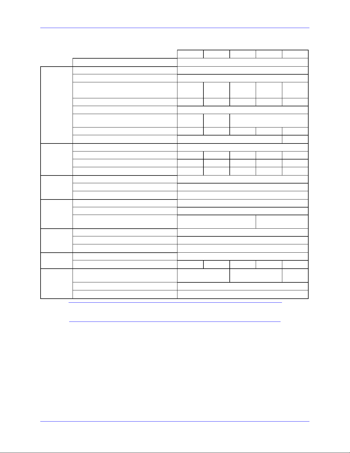
Geo PMAC Feedback Options
Default Configuration:
Quadrature Encoders,
or SSI Absolute
Encoders and Hall
Model
GIxxxxx0
GIxxxxx1
GIxxxxx2
GIxxxxx3
GIxxxxx4
GIxxxxx5
GIxxxxLx Lookahead firmware option
GIxxxxMx Ethernet Modbus TCP
GIxxxxTx Combination of Lookahead option and Modbus
Effect inputs
√
√
√
√ √
√ √
√ √
Analog (Sin/Cos)
Encoders: x4096
Interpolator
Resolver to Digital
Converters
Absolute
Encoder
Interface:
Endat
Hiperface
Addition of two channels
of 16-bit A/D converters
with each feedback option
and one 12-bit filtered
PWM- DAC output
Package Types
Geo package types provide various power levels and one or two axis capability with three different
package types.
The Geo Drive has a basic package size of 3.3"W x 9.875"H x 8.0"D (84mm W x 251mm H x 203mm
D). This size includes the heat sink and fan. In this package size, Single Width, the Geo can handle one
or two low-to-medium power axes OR only a single axis for medium to high power.
The mechanical design of the Geo drive is such that it allows two heat sinks to be easily attached together
so as to provide two high power axes in a Double Width configuration. This double package size is 6.5"
W x 9.875" H x 8.0" D (165 mm W x 251 mm H x 203 mm D). It provides a highly efficient package
size containing two axes of up to about 10kW each thus driving nearly 24kW of power, but using a single
interface card. This results in a highly cost efficient package.
There is also one more package type only for the low power (1.5A/4.5A) single width Geo drive, model
GIx012xx. This package substitutes the heatsink and the fan with a smaller plate which has the same
mounting pattern with the regular single width drive making the unit’s depth 2.2 inches (56 mm) less than
the single width drive, 5.8" D.
• Low Profile: GIx012xx (only)
3.3" wide (84 mm) (no heatsink, no fan), Maximum Power Handling ~1200 watts
Package Dimensions: 3.3" W x 9.875" H x 5.8" D (84 mm W x 251 mm H x 148 mm D)
Weight: 4.3lbs. (1.95kgs)
• Single Width: GIx051xx, GIx101xx, GIx151xx, GIH032xx, GIx052xx and GIL102xx
3.3" wide (84 mm)(with heatsink and fan), Maximum Power Handling ~12000 watts
GIL032xx Single Width, with heatsink, no Fan (Weight 5.4lbs/2.45kgs)
Package Dimensions: 3.3" W x 9.875" H x 8.0" D (84 mm W x 251 mm H x 203 mm D)
Weight: 5.5lbs. (2.50kgs)
• Double Width: GIx201xx, GIx301xx, GIH102xx and GIx152xx.
6.5” wide (164mm) (with heatsink and fan), Maximum Power Handling ~24,000 watts
Package Dimensions: 6.5" W x 9.875" H x 8.0" D (164mm W x 251 mm H x 203 mm D)
Weight: 11.6lbs (5.3kgs)
8 Specifications
Page 19

Geo PMAC Drive User Manual
g
g
Electrical Specifications
240VAC Input Drives
Nominal Input Voltage (VAC)
Rated Input Voltage (VAC)
Rated Continuous Input Current (A
AC
)
Main
Input
Power
Output
Power
Bus
Protection
Shunt
Re
ulator
Ratings
Control
Lo
ic
Power
Current
Feedback
Transistor
Control
RMS
Rated Input Power (Watts)
Frequency (Hz)
Phase Requirements
Charge Peak Inrush Current (A)
Main Bus Capacitance (µf)
Rated Output Voltage (V)
Rated Cont. Output Current per Axis
Peak Output Current (A) for 2 seconds
Rated Output Power per Axis (Watts)
Nominal DC Bus
Over-voltage Trip Level (VDC)
Under-voltage Lockout Level (VDC)
Turn-On Voltage (VDC)
Turn-Off Voltage (VDC) 372
Delta Tau Recommended Load Resistor
(300 W Max.)
Input Voltage (VDC)
Input Current (A)
Inrush Current (A)
Resolution (bits)
Full-scale Signed Reading (±A)
Delta Tau Recommended PWM
Frequency (kHz) @rated current
Minimum Dead Time (µs)
Charge Pump Time (% of PWM period.)
GxL051 GxL101 GxL151 GxL201 GxL301
230
97-265
3.3 6.6 9.9 13.2 19.8
1315 2629 3944 5259 7888
50/60
1Φ or 3Φ 3Φ
3380 5020 6800
138
5 10 15 20 30
10 20 30 40 60
1195 2390 3585 4780 7171
325
410
10
392
GAR78 GAR48 GAR48-3
20-27
2A
4A
12
16.26 32.53
12 10 8
48.79 65.05 97.58
1
5
Note:
All values at ambient temperature of 0-45°C (113F) unless otherwise stated.
Specifications 9
Page 20
Geo PMAC Drive User Manual
g
g
Main
Input
Power
GxL012 GxL032 GxL052 GxL102 GxL152
Output Circuits (axes)
Nominal Input Voltage (VAC)
Rated Input Voltage (VAC)
Rated Continuous Input Current (A
AC
)
RMS
Rated Input Power (Watts)
Frequency (Hz)
Phase Requirements
1.98 3.96 6.6 13.2 19.8
789 1578 2629 5259 7888
1Φ or 3Φ 1Φ or 3Φ 3Φ
2
230
97-265
50/60
Output
Power
Bus
Protection
Shunt
Re
ulator
Ratings
Control
Lo
ic
Power
Current
Feedback
Transistor
Control
Charge Peak Inrush Current (A)
Main Bus Capacitance (µf)
Rated Output Voltage (V)
Rated Cont. Output Current per Axis
Peak Output Current (A) for 2 seconds
Rated Output Power per Axis (Watts)
Nominal DC Bus
Over-voltage Trip Level (VDC)
Under-voltage Lockout Level (VDC)
Turn-On Voltage (VDC)
Turn-Off Voltage (VDC)
Delta Tau Recommended Load Resistor
(300 W Max.)
Input Voltage (VDC)
Input Current (A)
Inrush Current (A)
Resolution (bits)
Full-scale Signed Reading (±A)
Delta Tau Recommended PWM
Frequency (kHz)
Minimum Dead Time (µs)
Charge Pump Time (% of PWM period.)
3380 5020
138
1.5 3 5 10 15
4.5 9 10 20 30
359 717 1195 2390 3585
325
410
10
392
372
GAR78 GAR48
20-27
2A
4A
12
7.32 14.64
16 12 10
16.26 32.53
1
5
48.79
Note:
All values at ambient temperature of 0-45°C (113F) unless otherwise stated.
10 Specifications
Page 21

Geo PMAC Drive User Manual
g
g
480VAC Input Drives
Main
Input
Power
Bus
Protection
Shunt
Re
ulator
Ratings
Control
Lo
ic
Power
Current
Feedback
Transistor
Control
Output Circuits (axes)
Nominal Input Voltage (VAC)
Rated Input Voltage (VAC)
Rated Continuous Input Current (A
AC
)
RMS
Rated Input Power (Watts)
Frequency (Hz)
Phase Requirements
Charge Peak Inrush Current (A)
Main Bus Capacitance (µf)
Rated Output Voltage (V) @ Rated
Current
Rated Cont. Output Current per Axis
Peak Output Current (A) for 2 seconds
Rated Output Power per Axis (Watts)
Nominal DC Bus
Over-voltage Trip Level (VDC)
Under-voltage Lockout Level (VDC)
Turn-On Voltage (VDC)
Turn-Off Voltage (VDC) 744
Delta Tau Recommended Load
Resistor (300 W Max.)
Input Voltage (VDC)
Input Current (A)
Inrush Current (A)
Resolution (bits)
Full-scale Signed Reading (±Amperes)
Delta Tau Recommended PWM
Frequency (KHz) @ rated current
Minimum Dead Time (µs)
Charge Pump Time (% of PWM
period.)
GxH051 GxH101 GxH151 GxH201 GxH301
1
480
300-525
3.3 6.6 9.9 13.2 19.8
2744 5487 8231 10974 16461
50/60
1Φ or 3Φ 3Φ
845 1255 1700
288
5 10 15 20 30
10 20 30 40 60
2494 4988 7482 9977 14965
678
828
20
784
GAR78 GAR48 GAR48-3
20-27
2A
4A
12
16.26 32.53 48.79 65.05 97.58
12 10 8
1.6
5
Specifications 11
Page 22

Geo PMAC Drive User Manual
g
g
Main
Input
Power
Bus
Protection
Shunt
Re
ulator
Ratings
Control
Lo
ic
Power
Current
Feedback
Transistor
Control
GxH012 GxH032 GxH052 GxH102 GxH152
Output Circuits (axes)
Nominal Input Voltage (VAC)
Rated Input Voltage (VAC)
Rated Continuous Input Current (A
AC
)
RMS
Rated Input Power (Watts)
Frequency (Hz)
Phase Requirements
Charge Peak Inrush Current (A)
Main Bus Capacitance (µf)
Rated Output Voltage (V) @ Rated
Current
Rated Cont. Output Current per Axis
Peak Output Current (A) for 2 seconds
Rated Output Power per Axis (Watts)
Nominal DC Bus
Over-voltage Trip Level (VDC)
Under-voltage Lockout Level (VDC)
Turn-On Voltage (VDC)
1.98 3.96 6.6 13.2 19.8
1646 3292 5487 10974 16461
1Φ or 3Φ 3Φ
1.5 3 5 10 15
4.5 9 10 20 30
748 1496 2494 4988 7482
2
480
300-525
50/60
845 1255
288
678
828
20
784
Turn-Off Voltage (VDC) 744
Delta Tau Recommended Load Resistor
(300 W Max.)
Input Voltage (VDC)
Input Current (A)
Inrush Current (A)
Resolution (bits)
Full-scale Signed Reading (±Amperes)
Delta Tau Recommended PWM
Frequency (KHz) @ rated current
Minimum Dead Time (µs)
Charge Pump Time (% of PWM period.)
7.32 14.64 16.26 32.53 48.79
GAR78 GAR48
20-27
2A
4A
12
12 10 8
1.6
5
Note:
All values at ambient temperature of 0-45°C (113F) unless otherwise stated.
12 Specifications
Page 23

Geo PMAC Drive User Manual
Environmental Specifications
Description Unit Specifications
Operating Temperature °C +0 to 45 (113F). Above 45°C, de-rate the continuous peak output
current by 2.5% per °C above 45°C. Maximum Ambient is 55°C (131F).
Rated Storage Temperature °C -25 to +70
Humidity % 10% to 90% non-condensing
Shock Call Factory
Vibration Call Factory
Operating Altitude Feet
(Meters)
Air Flow Clearances in (mm) 3" (76.2mm) above and below unit for air flow
To 3300 feet (1000 meters). De-rate the continuous and peak output
current by 1.1% for each 330 feet (100 meters) above the 3300 feet
Recommended Fusing and Wire Gauge
Model Recommended Fuse
(FRN/LPN)
GIL012xx 15 14 AWG
GIL032xx 20 12 AWG
GIL051xx 20 12 AWG
GIL052xx 20 12 AWG
GIL101xx 20 12 AWG
GIL102xx 20 12 AWG
GIL151xx 25 10 AWG
GIL152xx 25 10 AWG
GIL201xx 25 10 AWG
GIL301xx 30 8 AWG
GIH012xx 15 14 AWG
GIH032xx 20 12 AWG
GIH051xx 20 12 AWG
GIH052xx 20 12 AWG
GIH101xx 20 12 AWG
GIH102xx 20 12 AWG
GIH151xx 25 10 AWG
GIH152xx 25 10 AWG
GIH201xx 25 10 AWG
GIH301xx 30 8 AWG
* See local and national code requirements
Wire Sizes
Geo Drive electronics create a DC bus by rectifying the incoming AC electricity. The current flow into
the drive is not sinusoidal but rather a series of narrow, high-peak pulses. Keep the incoming impedance
small to not hinder these current pulses. Conductor size, transformer size, and fuse size recommendations
may seem larger than normally expected. All ground conductors should be 8AWG minimum using wires
constructed of many strands of small gauge wire. This provides the lowest impedance to high-frequency
noises.
Recommended Wire Gauge*
Specifications 13
Page 24

Geo PMAC Drive User Manual
14 Specifications
Page 25

Geo PMAC Drive User Manual
RECEIVING AND UNPACKING
Delta Tau products are thoroughly tested at the factory and carefully packaged for shipment. When the
Geo Drive is received, do the following immediately.
1. Observe the condition of the shipping container and report any damage immediately to the
commercial carrier that delivered the drive.
2. Remove the drive from the shipping container and remove all packing materials. Check all shipping
material for connector kits, documentation, diskettes, CD ROM, or other small pieces of equipment.
Be aware that some connector kits and other equipment pieces may be quite small and can be
accidentally discarded if care is not used when unpacking the equipment. The container and packing
materials may be retained for future shipment.
3. Verify that the part number of the drive received is the same as the part number listed on the purchase
order.
4. Inspect the drive for external physical damage that may have been sustained during shipment and
report any damage immediately to the commercial carrier that delivered the controller.
5. Electronic components in this amplifier are design-hardened to reduce static sensitivity. However,
use proper procedures when handling the equipment.
6. If the Geo Drive is to be stored for several weeks before use, be sure that it is stored in a location that
conforms to published storage humidity and temperature specifications stated in this manual.
Use of Equipment
The following guidelines describe the restrictions for proper use of the Geo Drive:
• The components built into electrical equipment or machines can be used only as integral components
of such equipment.
• The Geo Drives are to be used only on grounded three-phase industrial mains supply networks (TN-
system, TT-system with grounded neutral point).
• The Geo Drives must not be operated on power supply networks without a ground or with an
asymmetrical ground.
• If the Geo Drives are used in residential areas, or in business or commercial premises, implement
additional filter measures.
• The Geo Drives may be operated only in a closed switchgear cabinet, taking into account the ambient
conditions defined in the environmental specifications.
Delta Tau guarantees the conformance of the Geo Drives with the standards for industrial areas stated in
this manual, only if Delta Tau components (cables, controllers, etc.) are used.
Geo PMAC drive is a combination of a PMAC2 controller and Geo Amplifier. So parallel with this
manual the user needs to use the PMAC1/2 Software reference
Note:
Always download the latest manual revision from the Delta Tau website
www.deltatau.com
manual and the PMAC USERS manual.
Receiving and Unpacking 15
Page 26

Geo PMAC Drive User Manual
Note:
If Ethernet communications is used, Delta Tau Systems strongly recommends use
of RJ45 CAT5e or better shielded cable.
Newer network cards have the Auto-MDIX feature that eliminates the need for
crossover cabling by performing an internal crossover when a straight cable is
detected during the auto-negotiation process.
For older network cards, one end of the link must perform media dependent
interface (MDI) crossover (MDIX), so that the transmitter on one end of the data
link is connected to the receiver on the other end of the data link (a crossover/patch
cable is typically used). If an RJ45 hub is used, then a regular straight cable must
be implemented..
Maximum length for Ethernet cable should not exceed 100m (330ft).
16 Receiving and Unpacking
Page 27

Geo PMAC Drive User Manual
MOUNTING
The location of the control is important. Installation should be in an area that is protected from direct
sunlight, corrosives, harmful gases or liquids, dust, metallic particles, and other contaminants. Exposure
to these can reduce the operating life and degrade performance of the control.
Several other factors should be evaluated carefully when selecting a location for installation:
• For effective cooling and maintenance, the control should be mounted on a smooth, non-flammable
vertical surface.
• At least 3 inches (76mm) top and bottom clearance must be provided for airflow. At least 0.4 inches
(10mm) clearance is required between controls (each side).
• Temperature, humidity and Vibration specifications should also be taken in account.
The Geo Drives can be mounted with a traditional 4-hole panel mount, two U shape/notches on the
bottom and two pear shaped holes on top. This keeps the heat sink and fan (single width and double
width drives), inside the mounting enclosure. On the low profile units (low power), the heat sink and fan
are replaced with a flat plate, and use the mounting enclosure itself as a heat sink and reduce the depth of
the Geo amplifier by about 2.2 inches (~56 mm) to a slim 5.8 inch D (150 mm D). Mounting is also
identical to the single and double width drives through the 4-hole panel mount.
If multiple Geo drives are used, they can be mounted side-by-side, leaving at least a 0.4inch clearance
between drives. This means a 3.7 inch center-to-center distance (94 mm) with the Single width and low
profile Geo drives. Double Width Geo amplifiers can be mounted side by side at 6.9 inch center-to-center
distance (175 mm).
It is extremely important that the airflow is not obstructed by the placement of conduit tracks or other
devices in the enclosure.
The drive is mounted to a back panel. The back panel should be unpainted and electrically conductive to
allow for reduced electrical noise interference. The back panel should be machined to accept the
mounting bolt pattern of the drive. Make sure that all metal chips are cleaned up before the drive is
mounted so there is no risk of getting metal chips inside the drive.
The drive is mounted to the back panel with four M4 screws and internal-tooth lock washers. It is
important that the teeth break through any anodization on the drive’s mounting gears to provide a good
electrically conductive path in as many places as possible. Mount the drive on the back panel so there is
airflow at both the top and bottom areas of the drive (at least three inches).
Caution:
Units must be installed in an enclosure that meets the environmental IP rating of
the end product (ventilation or cooling may be necessary to prevent enclosure
ambient from exceeding 45° C [113° F ]).
The figures below show the mounting dimensions of the drives.
Note:
For more detail drawings (SolidWorks, eDrawings, DXF) visit our website under
the product that you are looking for.
Mounting 17
Page 28
Geo PMAC Drive User Manual
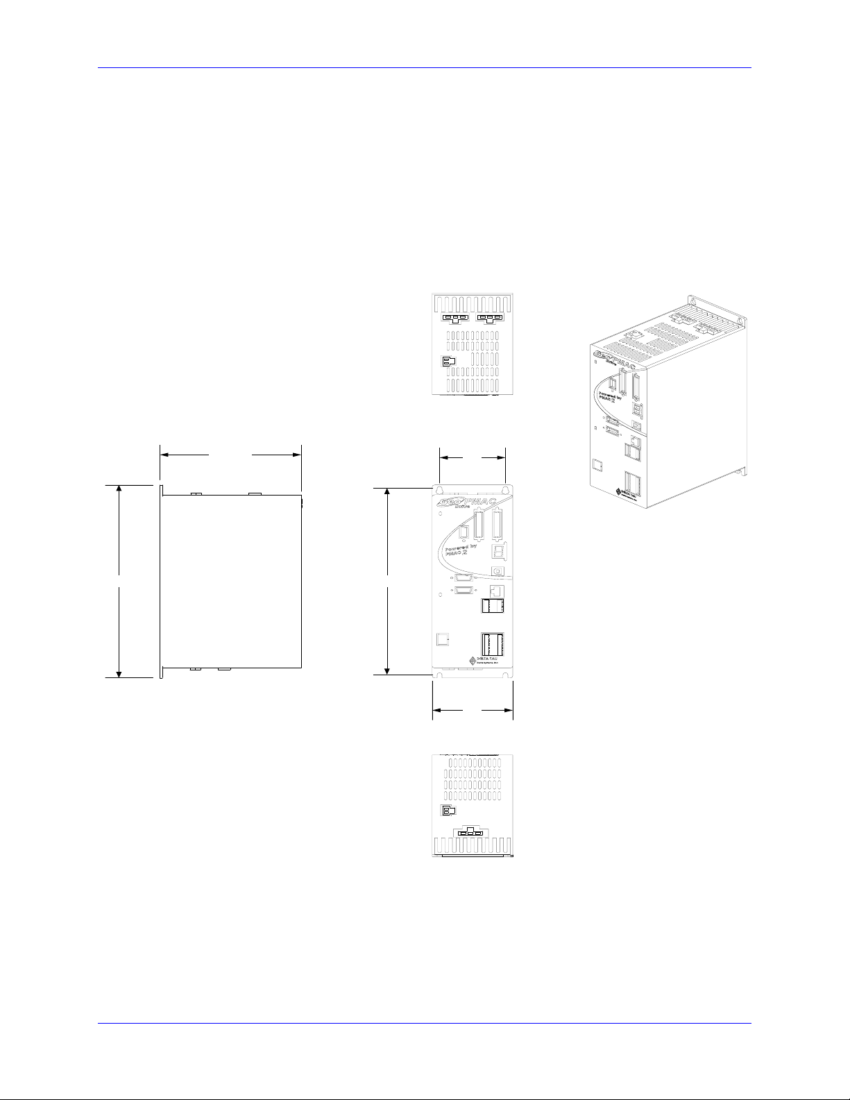
Low Profile
GIx012xx (only)
Geo PMAC
Low Profile, Dual Axis
(Without Heatsink, Without Fan )
GIL012XX, GIH012XX
11.00
(5.790)
2.7
10.625
3.3
18 Mounting
Page 29
Geo PMAC Drive User Manual
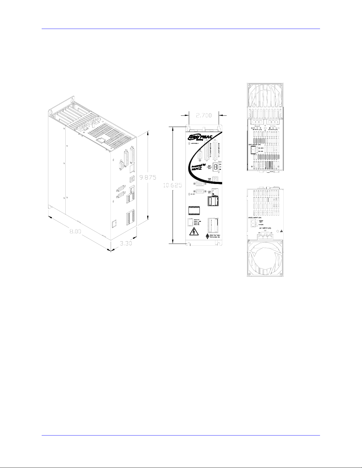
Single Width
GIx051xx, GIx101xx, GIx151xx, GIx032, GIx052xx, and GIL102xx
A
N
A
L
O
G
I
/
O
(
X
7
)
S ENCODER 1 (X8)
S ENCODER 2 (X9)
TOP VIEW
+3.3V
GND
GND
EQU1
EQU2
FL RT1
FL RT2
USER1
USER2
MLIM1
MLIM2
PLIM1
PLIM2
HOME1
HOME2
WARNING!
Residual Voltage.
Wait 5 minutes after
removing power
before servicing unit.
SAFETY RELAY (X4)
(X4)
N/A
WARNING:
HIGH VOLTAGE!
DISCRETE I/O (X10)
GENERAL PURPOSE I/O (X3)
COM EMT
COM COL
IN COM 5-8
IN COM 1-4
GP IN8
GP IN7
GP IN6
GP IN5
GP IN4
GP IN3
GP IN2
GP IN1
GP O6GP O6+
GP O5GP O5+
GP O4GP O4+
GP O3GP O3+
GP O2GP O2+
GP O1GP O1+
BOTTOM VIEW
Mounting 19
Page 30
Geo PMAC Drive User Manual
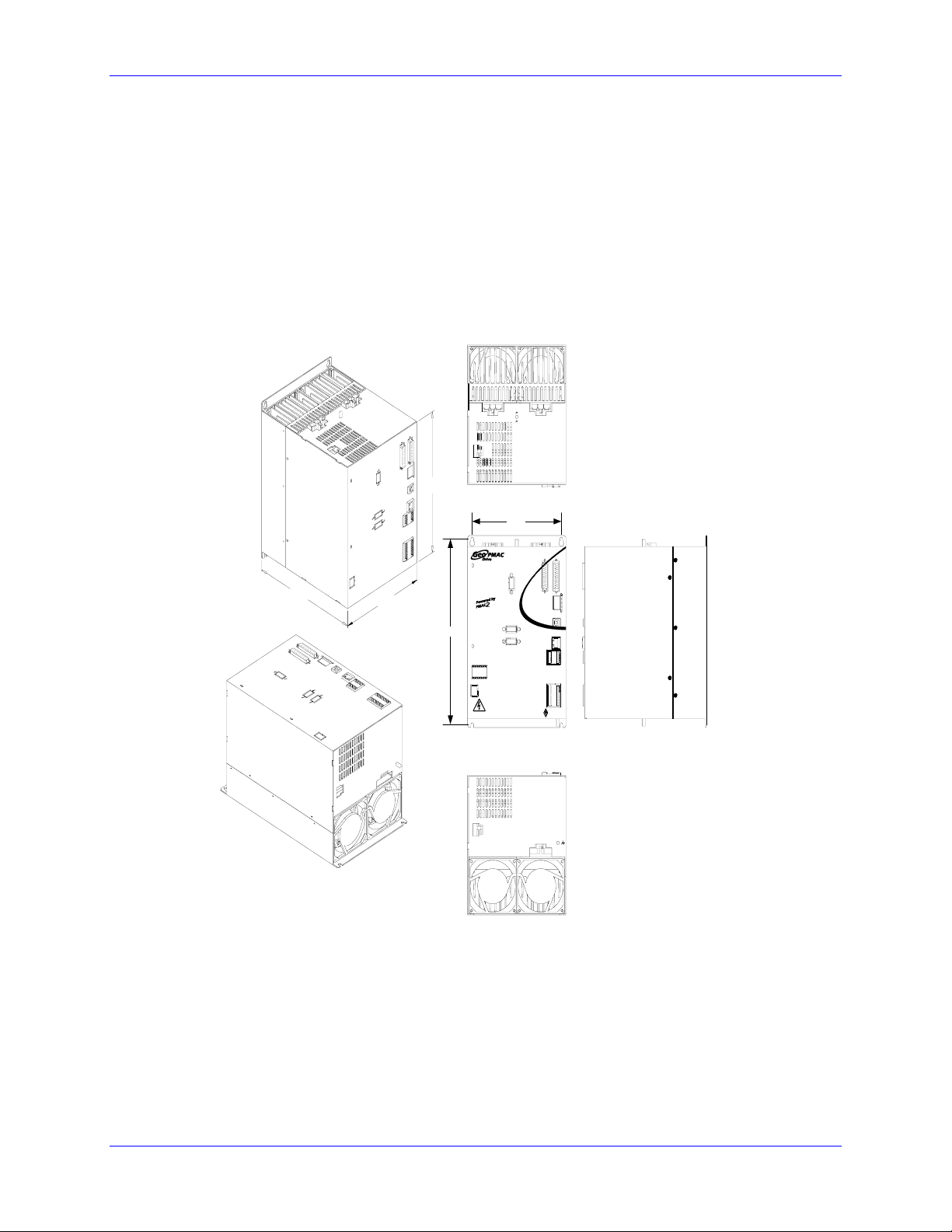
Double Width
GIx201xx and GIx301xx (single axis), GIH102xx and GIx152xx (dual axis)
GIH102, GIL152 & GIH152
10.0/20.0 & 15.0/30.0 AMPS CONT/PEAK (306-603705 )
PMAC Version, Internal Heatsink Mtg ,
Double wide with 2 Fans
8.00
6. 46
9.875
10. 625
EXT SHUNT (J 5)
SAFETY RELAY (X4)
24VDC INPUT (J4)
GATE ENABLE
DC BUS
WARNI NG !
Resid ual Vo ltage.
Wait 5 minutes after
remov ing power
before ser vic ing unit.
(X4)
N/A
WARNIN G:
HIGH VOLTAGE!
RELAY N/O
RELAY COMM
RELAY WB
RELAY WA
W U
MOTOR 2 (J3)
REGEN +
REGEN -
24VDC
RET
+24VDC
WVU
V
MOTOR 1 (J2)
5.860
ENCODER INPUT 1 (X1)
ENCODER INPUT 2 (X2)
ANALO G I/O (X7)
USB
REG
AMP
+5V
STATUS
(D1)
W
D
+3.3V
USB
S ENCODER 1 (X8)
(X5)
S ENCODER 2 (X9)
RJ45
(X6)
GND
GND
EQU2
EQU1
FL RT2
FL RT1
USER2
USER1
MLIM2
MLIM1
PLIM2
PLIM1
HOME2
HOME1
DISCRETE I/O (X10)
GENERAL PURPOSE I/O (X3)
COM EMT
GP O6-
COM COL
GP O6+
IN COM 5-8
GP O5-
IN COM 1-4
GP O5+
GP O4-
GP IN8
GP O4+
GP IN7
GP O3-
GP IN6
GP O3+
GP IN5
GP O2-
GP IN4
GP O2+
GP IN3
GP O1-
GP IN2
GP O1+
GP IN1
DELTA TAU
Data Systems, Inc .
AC I N PU T (J1)
L2
L1 L3
20 Mounting
Page 31

Geo PMAC Drive User Manual
CONNECTIONS
System (Power) Wiring
MAIN
POWER
OPTI ONAL
EMI FILTER
EARTH
BLOCK
MCR
BLK
BLK
Fusing
GARxx
SHUNT
RESISTOR
24V
POWER
SUPPLY
WHT
WHT
EARTH
FRAME
+24 V
Red
Blk
24V R ET
Twisted Wires
WARNING:
RE GEN -
SHUN T
J4
LOGIC
24 VDC RET
BLK
J5
+24 VDC
RED
GRN\Y EL
RE GEN +
Geo
Pmac
Drive
MOTOR 2
SC RE W HE AD
BLK
BLU
J3
WHT
MOTOR 1
J1
AC IN PUT
L
L2L
1
Motor 2
BLK
BLU
GRN\Y EL
WHT
WVUWVU
J2
SCREW HEAD
X1X2
SCREW HEAD
3
t
e
xt
t
e
xt
8AWG
to Main
Earth
Block
Motor 1
t
e
xt
t
e
xt
Encoders
Installation of electrical control equipment is subject to many regulations including
national, state, local, and industry guidelines and rules. General recommendations
can be stated but it is important that the installation be carried out in accordance
with all regulations pertaining to the installation.
Fuse and Circuit Breaker Selection
In general, fusing must be designed to protect the weakest link from fire hazard. Each Geo drive is
designed to accept more than the recommended fuse ratings. External wiring to the drive may be the
weakest link as the routing is less controlled than the drive’s internal electronics. Therefore, external
circuit protection, be it fuses or circuit breakers, must be designed to protect the lesser of the drive or
external wiring.
High peak currents and high inrush currents demand the use of slow blow type fuses and hamper the use
of circuit breakers with magnetic trip mechanisms. Generally, fuses are recommended to be larger than
what the rms current ratings require. Remember that some drives allow three times the continuous rated
current on up to two axis of motion. Time delay and overload rating of protection devices must consider
this operation.
System Wiring 21
Page 32

Geo PMAC Drive User Manual
Use of GFI Breakers
Ground Fault Interrupter circuit breakers are designed to break the power circuit in the event that
outgoing currents are not accompanied by equal and opposite returning currents. These breakers assume
that if outgoing currents are not returning then there is a ground path in the load. Most circuit breakers of
this type account for currents as low as 10mA PWM switching in servo drives coupled with parasitic
capacitance to ground in motor windings and long cables generate ground leakage current. Careful
installation practices must be followed. The use of inductor chokes in the output of the drive will help
keep these leakage currents below breaker threshold levels.
Transformer and Filter Sizing
Incoming power design considerations for use with Geo Drives require some over rating. In general, it is
recommended that all 3-phase systems using transformers and incoming filter chokes be allotted a 25%
over size to keep the impedances of these inserted devices from affecting stated system performance. In
general, it is recommended that all single-phase systems up to 1kW be designed for a 50% overload. All
single-phase systems over 1kW should be designed for a 200% overload capacity.
Noise Problems
When problems do occur often it points to electrical noise as the source of the problem. When this
occurs, turn to controlling high-frequency current paths. If following the grounding instructions does not
work, insert chokes in the motor phases. These chokes can be as simple as several wraps of the individual
motor leads through a ferrite ring core (such as Micrometals T400-26D). This adds high-frequency
impedance to the outgoing motor cable thereby making it harder for high-frequency noise to leave the
control cabinet area. Care should be taken to be certain that the core’s temperature is in a reasonable
range after installing such devices.
Operating Temperature
It is important that the ambient operating temperature of the Geo Drive be kept within specifications. The
Geo Drive should be installed in an enclosure such as a NEMA cabinet. The internal temperature of the
cabinet must be kept under the Geo Drive Ambient Temperature specifications. It is sometimes desirable
to roughly calculate the heat generated by the devices in the cabinet to determine if some type of
ventilation or air conditioning is required. For these calculations the Geo Drive’s internal heat losses
must be known. Budget 100W per axis for 1.5 amp drives, 150W per axis for 3 amp drives, 200W per
axis for 5 amp drives, 375W per axis for 10 Amp drives, and 500W per axis for 15 Amp drives.
From 0°C to 45°C (113F) ambient, no de-rating required. Above 45°C, derate the continuous and peak
output current by 2.5% per °C above 45°C. Maximum ambient is 55°C (131F).
Single Phase Operation
Due to the nature of power transfer physics, it is not recommended that any system design attempt to
consume more than 2kW from any single-phase mains supply. Even this level requires careful
considerations. The simple bridge rectifier front end of the Geo Drive, as with all other drives of this
type, require high peak currents. Attempting to transfer power from a single-phase system getting one
charging pulse each 8.3 milliseconds causes excessively high peak currents that can be limited by power
mains impedances. The Geo Drive output voltage sags, the input rectifiers are stressed, and these current
pulses cause power quality problems in other equipment connected to the same line. While it is possible
to operate drives on single-phase power, the actual power delivered to the motor must be considered.
Never design expecting more than 1.5 HP total from any 115V single-phase system and never more than
2.5 HP from any 230V single-phase system.
22 System Wiring
Page 33

Geo PMAC Drive User Manual
Wiring AC Input, J1
The main bus voltage supply is brought to the Geo drive through connector J1. 1.5A continuous and 3A
continuous Geo drives can be run off single-phase power. It is acceptable to bring the single-phase power
into any two of the three input pins on connector J1. Higher-power drive amplifiers require three-phase
input power. It is extremely important to provide fuse protection or overload protection to the input
power to the Geo drive amplifier. Typically, this is provided with fuses designed to be slow acting, such
as FRN-type fuses. Due to the various regulations of local codes, NEC codes, UL and CE requirements,
it is very important to reference these requirements before making a determination of how the input power
is wired.
Additionally, many systems require that the power be able to be turned on and off in the cabinet. It is
typical that the AC power is run through some kind of main control contact within the cabinet, through
the fuses, and then fed to a Geo drive. If multiple Geo drives are used, it is important that each drive has
its own separate fuse block.
Whether single- or three-phase, it is important that the AC input wires be twisted together to eliminate
noise radiation as much as possible. Additionally, some applications may have further agency noise
reduction requirements that require that these lines be fed from an input filtering network.
The AC connections from the fuse block to the Geo drive are made via a cable that is either purchased as
an option from Delta Tau (CABKITxx) or made with the appropriate connector kit (CONKITxx).
(Appendix A)
J1: AC Input Connector Pinout
Pin # Symbol Function Description Notes
1 L3 Input Line Input Phase 3
2 L2 Input Line Input Phase 2
3 L1 Input Line Input Phase 1 (Not used for single Phase input)
On Gxx201xx and Gxx301xx, there is a fourth pin for GROUND connection.
If DC bus is used, use L3 for DC+ and L2 for DC return.
Connector is located at the bottom side of the unit
Wiring Earth-Ground
Panel wiring requires that a central earth-ground location be installed at one part of the panel. This
electrical ground connection allows for each device within the enclosure to have a separate wire brought
back to the central wire location. The ground connection is usually a copper plate directly bonded to the
back panel or a copper strip with multiple screw locations. The Geo drive is brought to the earth-ground
via a wire connected to the M4 stud (5mm thread) on the top of the location through a heavy gauge,
multi-strand conductor to the central earth-ground location. On some models, a fourth pin is provided on
the 3-phase AC input connector (J1) and on the motor output connectors to provide a ground connection.
Earth Grounding Paths
High-frequency noises from the PWM controlled power stage will find a path back to the drive. It is best
that the path for the high-frequency noises be controlled by careful installation practices. The major
failure in problematic installations is the failure to recognize that wire conductors have impedances at
high frequencies. What reads 0 ohms on a handheld meter may be hundreds of ohms at 30MHz.
Consider the following during installation planning:
1. Star point all ground connections. Each device wired to earth ground should have its own conductor
brought directly back to the central earth ground plate.
2. Use unpainted back panels. This allows a wide area of contact for all metallic surfaces reducing high
frequency impedances.
3. Conductors made up of many strands of fine conducts outperform solid or conductors with few
System Wiring 23
Page 34

Geo PMAC Drive User Manual
strands at high frequencies.
4. Motor cable shields should be bonded to the back panel using 360-degree clamps at the point they
enter or exit the panel.
5. Motor shields are best grounded at both ends of the cable. Again, connectors using 360-degree shield
clamps are superior to connector designs transporting the shield through a single pin. Always use
metal shells.
6. Running motor armature cables with any other cable in a tray or conduit should be avoided. These
cables can radiate high frequency noise and couple into other circuits.
Wiring 24 V Logic Control, J4
An external 24VDC power supply is required to power the logic portion of the Geo drive. This power can
remain on, regardless of the main AC input power, allowing the signal electronics to be active while the
main motor power control is inactive. The 24V is wired into connector J4. The polarity of this
connection is extremely important. Carefully follow the instructions in the wiring diagram. This
connection can be made using 16 AWG wire directly from a protected power supply. In situations where
the power supply is shared with other devices, it may be desirable to insert a filter in this connection.
The power supply providing this 24V must be capable of providing an instantaneous current of at least
1.5A to be able to start the DC-to-DC converter in the Geo drive. In the case where multiple drives are
driven from the same 24V supply, it is recommended that each drive be wired back to the power supply
terminals independently. It is also recommended that the power supply be sized to handle the
instantaneous inrush current required to start up the DC-to-DC converter in the Geo drive.
J4: 24VDC Input Logic Supply Connector
Pin # Symbol Function Description Notes
1
2 +24VDC Input Control power input 24V+/-10%, 2A
Connector is located at the bottom side of the unit
24VDC RET Common Control power return
Wiring the Motors
The cable wiring must be shielded and have a separate conductor connecting the motor frame back to the
drive amplifier. The cables are available in cable kits (CABKITxx) from Delta Tau (see Appendix A).
Motor phases are conversed in one of three conventions. Motor manufacturers will call the motor phases
A, B, or C. Other motor manufacturers call them U, V, W. Induction motor manufacturers may call them
L1, L2, and L3. The drive’s inputs are called U, V, and W. Wire U, A, or L1 to the drive’s U terminal.
Wire V, B, or L2 to the drive’s V terminal. Wire W, C, or L3 to the drive’s W terminal.The motor’s
frame drain wire and the motor cable shield must be tied together at the mounting stud (5mm thread) on
top of the Geo drive product.
J2: Motor 1 Output Connector Pinout
Pin # Symbol Function Description Notes
1 U Output Axis 1 Phase1
2 V Output Axis 1 Phase2
3 W Output Axis 1 Phase3
On Gxx201xx and Gxx301xx, there is a fourth pin for ground connection.
Connector is located at the top side of the unit, for Ground connection use the screw with a lug
J3: Motor 2 Output Connector Pinout (Optional)
Pin # Symbol Function Description Notes
1 U Output Axis 2 Phase1 2- Axis drives only
2 V Output Axis 2 Phase2 2- Axis drives only
3 W Output Axis 2 Phase3 2- Axis drives only
Connector is located at the top side of the unit, for Ground connection use the screw with a lug
24 System Wiring
Page 35

Geo PMAC Drive User Manual
Wiring the Motor Thermostats
Some motor manufacturers provide the motors with integrated thermostat overload detection capability.
Typically, it is in one or two forms: a contact switch that is normally closed or a PTC. These sensors can
be wired into the Geo drive’s front panel at connector X1 and X2. Motor 1 thermostat output is wired to
pin 23 of X1, In_Therm_Mot1, and referenced to the GND pin13 or 25. In addition, if dual axis drive is
ordered, Motor 2 thermostat output is wired to pin 23 of X2, In_Therm_Mot2, and referenced to the
GND pin 13 or 25.
I1013 was specially created ( firmware 1.17C and above) for Geo PMAC drives to enable the motor overtemperature function of the drive, default this function is disabled. If someone wants to enable the motor
#1 temperature input switch to his Geo then he needs to set I1013=1. For motor #2 over-temperature input
to be enabled I1013=2 and if the user wants both motor over-temperature inputs enable then I1013=3.
For earlier drives (firmware 1.17A and 1.17B) If the motor over-temperature protection is not required,
In_Therm_Mot1/2 should be connected to GND, pin 13 or 25 of X1/X2 respectively. Otherwise, the
drive status display will show a warning error code 5 for motor #1 over -temperature, or an A for motor
#2 over-temperature. If both pins are not shorted to GND, display will show 5 (the first error that gets
triggered).
On the right side there is an example on how the
user could wire to the thermostats.
Function Pin
Motor Thermostat Input 23
GND 13,25
Wiring the Motor Thermostats
X1/X2
1
14
2
15
3
16
4
17
5
18
6
19
7
20
8
21
9
22
10
23
In_Therm_Mot
11
24
12
25
13
GND
Wiring the Regen (Shunt) Resistor J5
The Geo Drive family offers compatible regen resistors as optional equipment. The regen resistor is used
as a shunt regulator to dump excess power during demanding deceleration profiles. The GAR48 and
GAR78 resistors are designed to dump the excess bus energy very quickly.
The regen circuit is also known as a shunt regulator. Its purpose is to dump power fed back into the drive
from a motor acting as a generator. Excessive energy can be dumped via an external load resistor. The
Geo product series is designed for operation with external shunt resistors of 48 Ω for the 10 and 15 amp
versions or 78 Ω for the 1.5, 3, and 5 amp versions. These are available directly from Delta Tau as
GAR48 and GAR78, respectively. These resistors are provided with pre-terminated cables that plug into
connector J5.
Each resistor is the lowest ohm rating for its compatible drive and is limited for use to 200 watts RMS.
There are times the regen design might be analyzed to determine if an external Regen resistor is required
or what its ratings can be. The following data is provided for such purpose.
System Wiring 25
Page 36

Geo PMAC Drive User Manual
Caution:
The black wires are for the thermostat and the white wires are for the regen resistor
on the external regen resistor (pictured below). These resistors can reach
temperatures of up to 200 degrees C. These resistors must be mounted away from
other devices and near the top of the cabinet. Additionally, precautions must be
made to ensure the resistors are enclosed and cannot be touched during operation
or anytime they are hot. Sufficient warning labels should be placed prominently
near these resistors.
The GAR regen resistors incorporate a thermal overload protection thermostat that opens when the core
temperature of the resistor exceeds 225 degrees C. This thermostat is available through the two black
leads exiting the resistor. It is important that these two leads be wired in a safety circuit that stops the
system from operating should the thermostat open.
J5: External Shunt Connector Pinout
Pin # Symbol
Function
1 Regen- Output
2 Regen+ Output
Connector is located at the top side of the unit
DT Connector part number #014-000F02-HSG and pins part number #014-043375-001
Molex Crimper tool p/n#63811-0400
For the high Current Drives, Gxx201xx and Gxx301xx , this connector is a 3 pin Large
Molex connector
1 CAP- Output
2 Regen- Output
3 Regen+ Output
Connector is located at the top side of the unit.
DT Connector part number #014-H00F03-049 and pins part number #014-042815-001.
Molex Crimper tool p/n#63811-1500
26 System Wiring
Page 37

Geo PMAC Drive User Manual
Shunt Regulation
When the motor is used to slow the moving load, this is called regenerative deceleration. Under this
operation, the motor is acting as a generator consuming energy from the load while passing the energy
into the DC Bus storage capacitors. Left unchecked, the DC Bus voltage can raise high enough to
damage the drive. For this reason there are protection mechanisms built into the Geo Drive product such
as shunt regulation and over-voltage protection.
The shunt regulator monitors the DC Bus voltage. If this voltage rises above a present threshold (Regen
Turn On Voltage), the Geo Drive will turn on a power device intended to place the externally mounted
regen resistor across the bus to dump the excessive energy. The power device keeps the regen resistor
connected across the bus until the bus voltage is sensed to be below the Regen Turn Off voltage at which
time the power device removes the resistor connection.
Minimum Resistance Value
The regen resistor selection requires that the resistance value of the selected resistor will not allow more
current to flow through the Geo Drive’s power device than specified.
Maximum Resistance Value
The maximum resistor value that will be acceptable in an application is one that will not let the bus
voltage reach the drive’s stated over voltage specification during the deceleration ramp time. The
following equations defining energy transfer can be used to determine the maximum resistance value.
Energy Transfer Equations
Regen, or shunt, regulation analysis requires study of the energy transferred during the deceleration
profile. The basic philosophy can be described as follows:
• The motor and load have stored kinetic energy while in motion.
• The drive removes this energy during deceleration by transferring to the DC bus.
• There are losses during this transfer, both mechanical and electrical, which can be significant in some
systems.
• The DC bus capacitors can store some energy.
• The remaining energy, if any, is transferred to the regen resistor.
Kinetic Energy
The first step is to ascertain the amount of kinetic energy in the moving system, both the motor rotor and
the load it is driving. In metric (SI) units, the kinetic energy of a rotating mass is:
1
2
E
where:
is the kinetic energy in joules, or watt-seconds (J, W-s)
E
K
J is the rotary moment of inertia in kilogram-meter
ω is the angular velocity of the inertia in radians per second (1/s)
If the values are not in these units, convert them. For example, if the speed is in revolutions per minute
(rpm), first multiply this value by 2π/60 to convert to radians per second.
When English mechanical units are used, there are additional conversion factors that must be included to
get the energy result to come out in joules. For example, if the rotary moment of inertia J is expressed in
lb-ft-sec
2
, the following equation should be used:
E
K
If the rotary moment of inertia J is expressed in lb-in-sec
E
K
J
ω
=
K
2
2
(kg-m2)
J678.0
=
=
ω
2
, the following equation should be used:
J0565.0
ω
2
2
System Wiring 27
Page 38

Geo PMAC Drive User Manual
ω
=
=
In standard metric (SI) units, the kinetic energy of a linearly moving mass is:
1
2
E =
mv
K
2
where:
is the kinetic energy in joules (J)
E
K
m is the mass in kilograms (kg)
v is the linear velocity of the mass in meters/second (m/s)
Here also, to get energy in Joules from English mechanical units, additional conversion factors are
required. To calculate the kinetic energy of a mass having a weight of W pounds, the following equation
can be used:
E ==
K
W
2
v
678.0
g
2
Wv0211.0
where:
E
is the kinetic energy in joules (J)
K
W is the weight of the moving mass in pounds (lb)
g is the acceleration of gravity (32.2 ft/sec
2
)
v is the linear velocity of the mass in feet per second (ft/sec)
Energy Lost in Transformation
Some energy will be lost in the transformation from mechanical kinetic energy to electrical energy. The
losses will be both mechanical, due to friction, and electrical, due to resistance. In most cases, these
losses comprise a small percentage of the transformed energy and can be ignored safely because this leads
to a conservative design. However, if the losses are significant and the system should not be overdesigned, calculate these losses.
In metric (SI) units, the mechanical energy lost due to Coulomb (dry) friction in a constant deceleration to
stop of a rotary system can be expressed as:
1
ω
=
E
LM
where:
is the lost energy in joules (J)
E
LM
T
is the resistive torque due to Coulomb friction in newton-meters (N-m)
f
ω is the starting angular velocity of the inertia in radians per second (1/s)
t
is the deceleration time in seconds (s)
d
If the frictional torque is expressed in the common English unit of pound-feet (lb-ft), the comparable
expression is:
E
LM
In metric (SI) units, the mechanical energy lost due to Coulomb (dry) friction in a constant deceleration to
stop of a linear system can be expressed as:
E =
LM
where:
E
is the lost energy in joules (J)
LM
T
is the resistive force due to Coulomb friction in newtons (N)
f
v is the starting linear velocity in meters/second (m/s)
t
is the deceleration time in seconds (s)
d
If the frictional force is expressed in the English unit of pounds (lb) and the velocity in feet per second
(ft/sec), the comparable expression is:
E
LM
t
T
d
f
2
t
T678.0
d
f
1
2
F
dvtf
F678.0
dvtf
28 System Wiring
Page 39

Geo PMAC Drive User Manual
(
−−−
=
The electrical resistive losses in a 3-phase motor in a constant deceleration to stop can be calculated as:
E =
LE
2
i
rms
2
t
R
pp
d
3
where:
is the lost energy in joules (J)
E
LE
i
is the current required for the deceleration in amperes (A), equal to the required deceleration torque
rms
divided by the motor’s (rms) torque constant K
R
is the phase-to-phase resistance of the motor, in ohms (Ω)
pp
t
is the deceleration time in seconds (s)
d
T
Capacitive Stored Energy in the Drive
The energy not lost during the transformation is initially stored as additional capacitive energy due to the
increased DC bus voltage. The energy storage capability of the drive can be expressed as:
E −=
C
1
2
VC
regen
2
V
2
nom
)
where:
E
is the additional energy storage capacity in joules (J)
C
C is the total bus capacitance in Farads
V
is the DC bus voltage at which the regeneration circuit would have to activate, in volts (V)
regen
V
is the normal DC bus voltage, in volts (V)
nom
Evaluating the Need for a Regen Resistor
Any starting kinetic energy that is not lost in the transformation and cannot be stored as bus capacitive
energy must be dumped by the regeneration circuitry in to the regen (shunt) resistor. The following
equation can be used to determine whether this will be required:
LE
E
C
If E
LM
E
E
E
excess
in this equation is greater than 0, a regen resistor will be required.
excess
E
K
Regen Resistor Power Capacity
A given regen resistor will have both a peak (instantaneous) and a continuous (average) power dissipation
limit. It is therefore necessary to compare the required peak and continuous regen power dissipation
requirements against the limits for the resistor.
The peak power dissipation that will occur in the regen resistor in the application will be:
2
V
peak
regen
R
100
timeon%
P =
peak
where:
is peak power dissipation in watts (W)
P
peak
V
is the DC bus voltage at which the regeneration circuit activates, in volts (V)
regen
R is the resistance value of the regen resistor, in ohms (Ω)
However, this power dissipation will not be occurring all of the time, and in most applications, only for a
small percentage of the time. Usually, the regen will only be active during the final part of a lengthy
deceleration, after the DC bus has charged up to the point where it exceeds the regen activation voltage.
The average power dissipation value can be calculated as:
avg
P
P−=
where:
P
is average power dissipation in watts (W)
avg
%on-time is the percentage of time the regen circuit is active
System Wiring 29
Page 40

Geo PMAC Drive User Manual
Note:
The Turn-on voltage for the Shunt circuitry for all low power Geo drives is 392V(
for High Power is 780V). There is a Hysteresis of 20V, so if the regen turns on @
392V(780V), it will not turn off until it drops to 372V(740V).
Bonding
The proper bonding of shielded cables is imperative for minimizing noise emissions and increasing
immunity levels. The bonding effect is to reduce the impedance between the cable shield and the back
panel.
Power input wiring does not require shielding (screening) if the power is fed to the enclosure via metal
conduit. If metal conduit is not used in the system, shielded cable is required on the power input wires
along with proper bonding techniques.
Filtering
CE Filtering
Apply proper bonding and grounding techniques, described earlier in this section, when incorporating
EMC noise filtering components to meet this standard.
Noise currents often occur in two ways. The first is conducted emissions passed through ground loops.
The quality of the system-grounding scheme inversely determines the noise amplitudes in the lines.
These conducted emissions are of a common-mode nature from line-to-neutral (ground). The second is
radiated high-frequency emissions that usually are capacitively coupled from line-to-line and are
differential in nature.
When mounting the filters, make sure the enclosure has an unpainted metallic surface. This allows more
surface area to be in contact with the filter housing, and provides a lower impedance path between the
housing and the back plane. The back panel should have a high frequency ground strap connection to the
enclosure frame and earth ground.
Input Power Filtering
Caution:
To avoid electric shock, do not touch filters for at least 10 seconds after removing
the power supply.
The Geo Drive electronic system components require EMI filtering in the input power leads to meet the
conducted emission requirements for the industrial environment. This filtering blocks conducted -type
emissions from exiting onto the power lines and provides a barrier for power line EMI.
Adequately size the system. The type of filter must be based on the voltage and current rating of the
system and whether the incoming line is single or three-phase. One input line filter may be used for
multi-axis control applications. These filters should be mounted as close to the incoming power as
possible so noise is not capacitively coupled into other signal leads and cables. Implement the EMI filter
according to the following guidelines:
• Mount the filter as close as possible to incoming cabinet power.
• When mounting the filter to the panel, remove any paint or material covering. Use an unpainted
metallic back panel, if possible.
• Filters are provided with a ground connection. All ground connections should be tied to ground.
• Filters can produce high leakage currents; they must be grounded before connecting the supply.
• Do not touch filters for a period of 10 seconds after removing the power supply.
30 System Wiring
Page 41

Geo PMAC Drive User Manual
Motor Line Filtering
Motor filtering may not be necessary for CE compliance of Geo Drives. However, this additional
filtering increases the reliability of the system. Poor non-metallic enclosure surfaces and lengthy,
unbonded (or unshielded) motor cables that couple noise line-to-line (differential) are some of the factors
that may lead to the necessity of motor lead filtering.
Motor lead noise is either common-mode or differential. The common-mode conducted currents occur
between each motor lead and ground (line-to-neutral). Differential radiated currents exist from one motor
lead to another (line-to-line). The filtering of the lines feeding the motor provides additional attenuation
of noise currents that may enter surrounding cables and equipment I/O ports in close proximity.
Differential mode currents commonly occur with lengthy motor cables. As the cable length increases, so
does its capacitance and ability to couple noise from line-to-line. While every final system is different
and every application of the product causes a slightly different emission profile, it may become necessary
to use differential mode chokes to provide additional noise attenuation to minimize the radiated
emissions. The use of a ferrite core placed at the Geo Drive end on each motor lead attenuates differential
mode noise and lowers frequency (30 to 60 MHz) broadband emissions to within specifications. Delta
Tau recommends a Fair-Rite P/N 263665702 (or equivalent) ferrite core.
Common mode currents occur from noise spikes created by the PWM switching frequency of the Geo
Drive. The use of a ferrite or iron-powder core toroid places common mode impedance in the line
between the motor and the Geo Drive. The use of a common mode choke on the motor leads may
increase signal integrity of encoder outputs and associated I/O signals.
I/O Filtering
I/O filtering may be desired, depending on system installation, application, and integration with other
equipment. It may be necessary to place ferrite cores on I/O lines to avoid unwanted signals entering and
disturbing the Geo.
System Wiring 31
Page 42

Geo PMAC Drive User Manual
32 System Wiring
Page 43

Geo PMAC Drive User Manual
CONNECTORS
Connector Pinouts
X1: Encoder Input 1
The main encoder input channels for the Geo Drive support a variety of encoder feedback types. 5V
supply to power the encoder is provided, along with four digital Hall sensors (UVWT) for phasing.
Quadrature Encoder Input, or SSI Absolute Encoders. Optional: Sinusoidal Encoder Input with x4096
Interpolation, Resolver Feedback, Endat and Hiperface Interfaces.
X1 Encoder Input 1
(DB-25 Female Connector)
Pin # Digital /SSI
Encoder
Symbol
Sinusoidal
Encoder
Symbol*
Resolver
Symbol*
1213
1011
2425
89
2223
Use for Incremental Encoder/Sinusoidal
Encoder/Resolver
67
2021
1819
1 ChA1+ Sin1+ N/A Axis 1 Encoder A+/Encoder Sine+/Not used
2 ChB1+ Cos1+ N/A Axis 1 Encoder B+/Encoder Cosine+/Not used
3 Index1+ Index1+ N/A Axis 1 Encoder Index+/Encoder Index+/Not used
4 N/A N/A ResSin1+ Axis 1 Not used/Not used/Resolver Sine+
5 N/A N/A ResCos1+ Axis 1 Not used/Not used/Resolver Cosine+
6 CLK+ AltSin1+/CLK
+
7 DAT+ AltCos1+/DA
T+
N/A Axis 1 SSI Clock+/Power On Position Sine+, for Endat
output CLK+/Not used
N/A Axis 1 SSI Data-/Power On Position Cosine+, for Endat
input DATA+/Not used
8 ChU1+ ChU1+ ChU1+ Axis 1 U Commutation+
9 ChW1+ ChW1+ ChW1+ Axis 1 W Commutation+
10 BVREF1 Axis 1 Buffered 2.5 Volt Reference
11 N/A N/A ResOut1 Axis 1 Not used/Not used/Resolver Excitation Output
12 Encoder
Power1
Encoder
Power1
N/A Encoder PWR/Encoder PWR/Not used. 5VDC
13 GND Common
14 ChA1- Sin1- N/A Axis 1 Encoder A-/Encoder Sine-/Not used
15 ChB1- Cos1- N/A Axis 1 Encoder B-/Encoder Cosine-/Not used
16 Index1- Index1- N/A Axis 1 Encoder Index-/Encoder Index-/Not used
17 N/A N/A ResSin1- Axis 1 Not used/Not used/Resolver Sine18 N/A N/A ResCos1- Axis 1 Not used/Not used/Resolver Cosine19 CLK- AltSin1-/CLK- N/A Axis 1 SSI Clock-/Power On Position Sine-, for Endat
output CLK-/Not used
20 DAT- AltCos1-
/DAT-
N/A Axis 1 SSI Data-/Power On Position Cosine-, for Endat
input DATA-/Not used
21 ChV1+ ChV1+ ChV1+ Axis 1 V Commutation+
22 ChT1+ ChT1+ ChT1+ Axis 1 T Commutation+ (supplemental Hall sensor)***
23 1_In_Therm_Mot Motor 1 Thermal Input Switch
24 +5V Axis 1, +5V Supply
25 GND Common
* The Analog Feedback Option 1 or 4 is required for these functions.
** The Serial Encoder Feedback Option 2 or 5 is required for these functions
*** Most Hall sensors do not use this line, so let it float if not used
1
2345
14151617
Connectors 33
Page 44

Geo PMAC Drive User Manual
X2: Encoder Input 2
The main encoder input channels for the Geo Drive support a variety of encoder feedback types. 5V
supply to power the encoder is provided, along with four digital Hall sensors (UVWT) for phasing.
Quadrature Encoder Input, or SSI Absolute Encoders. Optional: Sinusoidal Encoder Input with x4096
Interpolation, Resolver Feedback, Endat and Hiperface Interfaces.
2345
X2 Encoder Input 2 (DB-25 Female Connector)
1213
1011
2425
89
2223
67
2021
1819
1
14151617
Pin # Digital /
SSI
Encoder
Sinusoidal
Encoder
Symbol*
Resolver
Symbol*
Use for Incremental Encoder/Sinusoidal
Encoder/Resolver
Symbol
1 ChA2+ Sin2+ N/A Axis 2 Encoder A+/Encoder Sine+/Not used
2 ChB2+ Cos2+ N/A Axis 2 Encoder B+/Encoder Cosine+/Not used
3 Index2+ Index2+ N/A Axis 2 Encoder Index+/Encoder Index+/Not used
4 N/A N/A ResSin2+ Axis 2 Not used/Not used/Resolver Sine+
5 N/A N/A ResCos2+ Axis 2 Not used/Not used/Resolver Cosine+
6
7
CLK+ AltSin2+/CLK+ N/A
DAT+ AltCos2+/DAT+ N/A
8 ChU2+ ChU2+ ChU2+ Axis 2 U Commutation+
9 ChW2+ ChW2+ ChW2+ Axis 2 W Commutation+
10 BVREF2 Axis 2 Buffered 2.5 Volt Reference
11 N/A N/A ResOut2 Axis 2 Not used/Not used/Resolver Excitation Output
12 Encoder
Encoder Power2 N/A Relay-Controlled Power/Relay-Controlled Power/Not used
Power2
13 GND Common
14 ChA2- Sin2- N/A Axis 2 Encoder A-/Encoder Sine-/Not used
15 ChB2- Cos2- N/A Axis 2 Encoder B-/Encoder Cosine-/Not used
16 Index2- Index2- N/A Axis 2 Encoder Index-/Encoder Index-/Not used
17 N/A N/A ResSin2- Axis 2 Not used/Not used/Resolver Sine18 N/A N/A ResCos2- Axis 2 Not used/Not used/Resolver Cosine19
20
CLK- AltSin2-/CLK- N/A
DAT- AltCos2-/DAT- N/A
21 ChV2+ ChV2+ ChV2+ Axis 2 V Commutation+
22 ChT2+ ChT2+ ChT2+ Axis 2 T Commutation+ + (supplemental Hall sensor)***
23 2_In_Therm_Mot Motor 2 Thermal Input Switch
24 +5V Axis 2, +5V Supply
25 GND Common
* The Analog Feedback Option 1 or 4 is required for these functions.
** The Serial Encoder Feedback Option 2 or 5 is required for these functions
*** Most Hall sensors do not use this line, so let it float if not used
Axis 2 SSI Clock+/Power On Position Sine+, for Endat
output CLK+/Not used
Axis2 SSI Data+/Power On Position Cosine+, for Endat
input DATA +/Not used
Default is Power ON, 5V
Axis 2 SSI Clock-/Power On Position Sine-, for Endat
output CLK-/Not used
Axis 2 SSI Data -/Power On Position Cosine-, for Endat
input DATA-/Not used
34 Connectors
Page 45

Geo PMAC Drive User Manual
X3: General Purpose I/O
Discrete I/O is available on the Geo PMAC Drive. All I/O is electrically isolated from the drive. Inputs
can be configured for sink or source applications (all eight inputs sinking or all eight inputs sourcing).
All I/O is 24V nominal operation, 0.5A maximum current. Outputs are robust against ESD and overload.
24
12 11 1 0
23 22 21 20 19 18 17 16 15 14 13
X3 General Purpose I/O (Two 12-pin Terminal Blocks Male)
Pin # Symbol Function Notes
1 GP Input 1/ HOME3 Input M1->X:$C010,16
2 GP Input 2/ PLIM3 Input M2->X:$C010,17
3 GP Input 3/ MLIM3 Input M3->X:$C010,18
4 GP Input 4/ User3 Input M4->X:$C010,19
5 GP Input 5/ HOME4 Input M5->X:$C018,16
6 GP Input 6/ PLIM4 Input M6->X:$C018,17
7 GP Input 7/ MLIM4 Input M7->X:$C018,18
8 GP Input 8/ USER4 Input M8->X:$C018,19
9 IN COM 1-4 Input Input 1-4 Common
10 IN COM 5-8 Input Input 5-8 Common
11 COL COM Input Common Collector
12 COM EMT Input Common Emitter
13 GP Output 1+ Output M9->Y:$FFC4,0 *
14 GP Output 1- Output M9->Y:$FFC4,0 **
15 GP Output 2+ Output M10->Y:$FFC4,1 *
16 GP Output 2- Output M10->Y:$FFC4,1 **
17 GP Output 3+ Output M11->Y:$FFC4,2 *
18 GP Output 3- Output M11->Y:$FFC4,2 **
19 GP Output 4+ Output M12->Y:$FFC4,3 *
20 GP Output 4- Output M12->Y:$FFC4,3 **
21 GP Output 5+ /EQU3 Output M311->Y:$FFC0,4 *
22 GP Output 5-/EQU3 Output M311->Y:$FFC0,4 **
23 GP Output 6+/EQU4 Output M411->Y:$FFC0,5 * ,2
24 GP Output 6-/EQU4 Output M411->Y:$FFC0,5 ** ,2
Note
6 5 123479 8
,1
,1
See notes on the following page regarding the I/O table above.
Connectors 35
Page 46

Geo PMAC Drive User Manual
*For sinking outputs, connect the COM EMIT (pin12) line to the Common GND (Analog Ground) and
the outputs to the individual plus output lines, e.g. GP OUTPUT 1+
**For sourcing outputs, connect the COM COL (pin11) line to 12-24V and the outputs to the individual
minus output lines, e.g., GP OUTPUT 1Topologies cannot be mixed, i.e., all sinking or all sourcing outputs. If the common emitter is used, the
common collector should be unconnected. Conversely, if the common collector is used, the common
emitter should be unconnected.
Inputs can be used as Flags for channels 3 and 4.
1,2
For outputs 5 and 6, use EQU 3 and EQU4 line respectively.
M13->X:$C015,11,1 ; EQU_3 compare flag latch control
M14->X:$C015,12,1 ; EQU_3 output write enable
M15->X:$C01D,11,1 ; EQU_4 compare flag latch control
M16->X:$C01D,12,1 ; EQU_4 output write enable
Part Type: FKMC 0,5/12-ST-2,5 p/n: 18 81 42 0
Since M13 (output 5) and M14 (output 6) are using the same address as EQU3 and EQU4, change them
as if you were latching EQU outputs. To do this, set M311=1 after each change to M13 (output5) and
M411=1 after each change to M14 (output6)
Output 5 ON: m13=1 m311=1
Output 5 OFF: m13=0 m311=1
Output 6 ON: m14=1 m411=1
Output 6 OFF: m14=0 m411=1
36 Connectors
Page 47

Geo PMAC Drive User Manual
Sample Wiring for the I/O, X3
GIx
Sourcing 1-8 Inputs
Sourcing 1-6 Outputs
24
2322212019181716151413
12
1110
GPO 6-
GPO 5-
GPO 4-
GPO 3-
GPO 2-
GPO 1-
INPUT Common 5-8
INPUT Common 1-4
Output 06
Output 05
Output 04
Output 03
Outpu t 02
Outpu t 01
COM_COL
24V Supply
0V 24V
GIx
Sinking 1-8 Inputs
Sinking 1-6 Outputs
24
2322212019181716151413
12
1110
GPO 6+
GPO 5+
GPO 4+
GPO 3+
GPO 2+
GPO 1+
COM_EMT
INPUT Common 5-8
INPUT Common 1-4
24V Supply
0V 24V
Output 06
Output 05
Output 04
Output 03
Output 02
Output 01
651 2 3 4 7 98
GIx
Sinking 1-4 Inputs
Sourcing 5-8 Inputs
Sinking 1-6 Outputs
24
2322212019181716151413
12
1110
651 2 3 4 7 98
GPO 6+
GPO 5+
GPO 4+
GPO 3+
GPO 2+
GPO 1+
INPUT Common 5-8
INPUT Common 1-4
Inputs
5-8
Inputs
1-4
Output 06
Output 05
Output 04
Output 03
Output 02
Output 01
COM_EMT
Inputs
5-8
24V Supply
0V 24V
651 2 3 4 7 98
Inputs
5-8
Inputs
1-4
GIx
Sourcing 1-4 Inputs
Sinking 5-8 Inputs
24V Supply
0V 24V
Sinking 1-6 Outputs
24
2322212019181716151413
12
1110
651 2 3 4 7 98
GPO 6+
GPO 5+
GPO 4+
GPO 3+
GPO 2+
GPO 1+
INPUT Common 5- 8
INPUT Common 1- 4
Output 06
Output 05
Output 04
Output 03
Output 02
Output 01
COM_EMT
Inputs
5-8
Inputs
1-4
Inputs
1-4
Connectors 37
Page 48

Geo PMAC Drive User Manual
X4: Safety Relay (Optional)
1 2 3 4
TB-4: 016-P L0F04-38P
Pin # Symbol Function
1 RELAY WA Safety Input 24V
2 RELAY WB Safety Input Return
3 RELAY COM Common
4 RELAY N/O Relay Normally Open
Part Type: MC 1, 5/4-ST-3, 81, PITCH 3.81MM PN:
1850686
If the Safety Relay option is installed, there is a dedicated Safety Input @24VDC (user supplied). When
the Safety Input is asserted, then the hardware will cut the 20V power to the gate drive which will prevent
all output from the power stage (the Gate Enable LED will turn off). If the user doesn’t need to use the
Safety Input and the drive has it installed, the user has to bypass it by wiring a 24VDC input to WA (pin
1) and the return (24VDC) to WB (pin 2).
Note:
There are no software configurable parameters to enable/disable or otherwise
manipulate the Safety Input functionality.
X5: USB 2.0 Connector
This connector is used in conjunction with USB A-B cable, which can be purchased from any local
computer store and is provided when Option 1A is ordered. The A connector is connected to a PC or Hub
device; the B connector plugs into the J9-USB port.
Pin # Symbol Function
1 VCC N.C.
2 D- DATA-
3 D+ DATA+
4 GND GND
5 SHELL SHIELD
6 SHELL SHIELD
X6: RJ45, Ethernet Connector
This connector is used for Ethernet communications from the Geo PMAC Drive to a PC.
Note:
Delta Tau Systems strongly recommends the use of RJ45 CAT5e or better shielded
cable.
Newer network cards have the Auto-MDIX feature that eliminates the need for
crossover cabling by performing an internal crossover when a straight cable is
detected during the auto-negotiation process.
For older network cards, one end of the link must perform media dependent
interface (MDI) crossover (MDIX), so that the transmitter on one end of the data
link is connected to the receiver on the other end of the data link (a crossover/patch
cable is typically used). If an RJ45 hub is used, then a regular straight cable must
38 Connectors
Page 49

Geo PMAC Drive User Manual
be implemented.
Maximum length for Ethernet cable should not exceed 100m (330ft).
X7: Analog I/O (Optional, Option 3/4/5)
Two analog inputs with 16 Bit A/D converter and one filtered PWM 12-bit analog output.
X7 Analog I/O
(DB-9 Female Connector)
Pin # Symbol Function Description Notes
1 AGND Common
2 DAC1- Output Filtered PWM 12-bit output +/-10V
3 AGND Common
4 ADC2+ Input Input level +/-10V
5 ADC1+ Input Input level+/-10V
6 DAC1+ Output Filtered PWM 12-bit output +/-10V
7 5V Output
8 ADC2- Input Input level +/-10V
9 ADC1- Input Input level+/-10V
Using the Analog Inputs A/D (X7)
The Geo PMAC Drive can be ordered with two analog-to-digital converters (Option 3/4/5). These A/D
converters are 16-bit devices that are ready to be used without any software setup. Delta Tau uses the
Burr Brown ADS8343 for this circuit.
The analog signals for analog input #1 are wired in to pins 5 (ADC1+) and 9 (ADC1-), and for analog
input #2 into pins 4 (ADC2+) and 8 (ADC2-).
When selected for bipolar mode, differential inputs allow the user to apply input voltages to ±10 volts
(20V p-p). When selected for unipolar mode, the user can apply input voltages from 0V to +10V (the
negative input ADCn- must be grounded).
To read the A/D data from the Geo PMAC device, create the M-variable definitions.
;The data received is an unsigned 16-bit number scaled from 0V to +10V (0cts to 32767cts).
M1000->Y:$FF58,8,16,u ;ADC1
M1001->Y:$FF78,8,16,u ;ADC2
;The data received is a signed 16-bit number scaled from –10V to +10V (-32767cts to 32767cts).
M1000->Y:$FF58,8,16,S ;ADC1
M1001->Y:$FF78,8,16,S ;ADC2
Using the Analog Output (X7)
When the Geo PMAC drive is ordered with either Option 3, 4, or 5, one differential 12-bit filtered PWM
analog output (analog output intended for use with loads > 5K impedance) is installed to the unit.
• Channel #3, Output M302->Y:$C012,8,16,s
• I369=6527 ; DAC limit 10Vdc
For example, if M302=653, the output should be approximately 1Vdc.
X8: S. Encoder 1
The Secondary Encoder channel allows an external encoder to be fed back on the controller. A 5V supply
is available for encoder power at pin 4. The three differential signal channels are brought into remaining
pins as indicated. The encoder loop feedback address is $C010
For example, to enter it in the ECT, write to the last empty entry (for this example entry 3):
WY:$722,$C010
Connectors 39
Page 50

Geo PMAC Drive User Manual
Ix03 and Ix04 =$722
X8 S. Enc. 1 (DB-9 Female Connector)
Pin # Symbol Function Notes
1 Cha1+ Input Secondary Encoder 1 A+
2 Chb1+ Input Secondary Encoder 1 B+
3 Index1+ Input Secondary Encoder 1 Index + /C+
4 5V Out Encoder Power
5 GND Out Common
6 Cha1- Input Secondary Encoder 1 A7 Chb1- Input Secondary Encoder 1 B8 Index1- Input Secondary Encoder 1 Index - /C-
9 N.C. Not Connected
40 Connectors
Page 51

Geo PMAC Drive User Manual
X9: S. Encoder 2
The Secondary Encoder channel allows an external encoder to be fed back on the controller. A 5V supply
is available for encoder power at pin 4. The three differential signal channels are brought into remaining
pins as indicated. The encoder loop feedback address is $C018.
For example, to enter it in the ECT, write to the last empty entry (for this example entry 4):
WY:$723,$C018
Ix03 and Ix04 =$723
X9 S. Enc. 2 (DB-9 Female Connector)
Pin # Symbol Function Notes
1 Cha2+ Input Secondary Encoder 2 A+
2 Chb2+ Input Secondary Encoder 2 B+
3 Index2+ Input Secondary Encoder 2 Index + /C+
4 5V Out Encoder Power
5 GND Out Common
6 Cha2- Input Secondary Encoder 2 A7 Chb2- Input Secondary Encoder 2 B8 Index2- Input Secondary Encoder 2 Index - /C-
9 N.C. Not Connected
Connectors 41
Page 52

Geo PMAC Drive User Manual
X10: Discrete I/O
The Geo PMAC limit and flag circuits also give the flexibility to wire in standard 12V to 24V limits and
flags or wire in 5V level limits and flags on a channel basis. The default is set for the standard 12V to
24V inputs but if the resistor pack is added to the circuit, the card can read 5V inputs.
14
13
12
11
10
9
8
X10 Discrete I/O
(Two 7-pin Terminal Blocks Male)
7
6
5
4
3
2
1
Pin # Symbol Function Description Notes
1 HOME1 Input Home Flag axis 1 M120->X:$C000,16,1
2 PLIM1 Input Positive Limit axis 1 M121->X:$C000,17,1
3 MLIM1 Input Negative Limit axis 1 M122->X:$C000,18,1
4 USER1 Input General User Flag 1 M115->X:$C000,19,1
5 FL_RT1 Input Return For All ch#1 Flags +V (12 to 24V) or 0V
6 EQU1- Output Compare Output M111->X:$C005
7 GND Common
8 HOME2 Input Home Flag axis 2 M220->X:$C008,16,1
9 PLIM2 Input Positive Limit axis 2 M221->X:$C008,17,1
10 MLIM2 Input Negative Limit axis2 M222->X:$C008,18,1
11 USER2 Input General User Flag 2 M215->X:$C008,19,1
12 FL_RT2 Input Return For All ch#2 Flags +V (12 to 24V) or 0V
13 EQU2- Output Compare Output M211->X:$C00D
14 GND Common
The Geo PMAC Drive limit and flag circuits also give the flexibility to wire in standard 12V to 24V
limits and flags or wire in 5V level limits and flags on a channel basis.
The default is set for the standard 12V to 24V inputs but if the resistor pack is added to the circuit, the
card can read 5V inputs.
If RP7 (limits 1) and RP8 (limits 2) are installed in the unit, the voltage level of the flags can be lowered
to 5V.
• RP7 and RP8 for 5V flags: 1Kohm Sip, 8-pin, four independent Resistors
• RP7 and RP8 for 12-24Vflags: Empty bank
Part Type: FKMC 0,5/7-ST-2,5 p/n: 18 81 37 0
Position Compare Port Driver IC
As with the other PMAC controllers, the Geo drive has the high-speed position compare outputs allowing
the firing of an output based on position. This circuit will fire within 100 nsec of reaching the desired
position. The position compare output port on the Geo PMAC drive has driver IC at component U27A
and U27B. This IC gives a fast CMOS driver.
The following table lists the properties of each driver IC:
Part # of Pins Max Voltage and Current Output Type Max Frequency
DS75452N 8 5V, 10 mA Totem-Pole (CMOS) 5 MHz
42 Connectors
Page 53

Geo PMAC Drive User Manual
Limit and Flag Circuit Wiring
The Geo PMAC allows the use of sinking or sourcing position limits and flags to the controller. The
opto-isolator IC used is a PS2705-4NEC-ND quad phototransistor output type. This IC allows the current
to flow from return to flag (sinking) or from flag to return (sourcing).
A sample of the positive limit circuit is shown below. The 4.7K resistor packs used will allow 12-24V
flag inputs. If 0-5V flags are used, then a 1KΩ resistor pack (RP) can be placed in either RP7 (channel 1)
or RP8 (channel 2). If these resistor packs are not added, all flags (±Limits, Home, User) will be
referenced from 12-24V.
Connecting Limits/Flags to the Geo Drive
The following diagrams illustrate the sinking and sourcing connections to a Geo Drive. This example
uses 12-24V flags.
24V
Return
Sinking
Separate
Flag Supply
12-24VDC
Flag
Supply
0V
24V
Flag
Flag Supply
12-24VDC
Sourcing
Separate
Supply
0V
Return
Connectors 43
Page 54

Geo PMAC Drive User Manual
Sample Wiring for the Flags, X10
GIx_Sourcing Flags
14
13
12
11
10
9
8
7
6
5
4
3
2
1
GND
FLG_RTN2
USER 2
Neg.Limit 2
Pos .Lim it 2
Home 2
GND
FLG_RTN1
Us er 1 Fl ag
Neg.Limit 1
Pos .Lim it 1
GIx_
Sourcing Flags channel #1
Sinking Flags channel #2
EQU 2
EQU 1
Home1
24V Supply
0V 24V
24V Supply
0V 24V
GIx_Sinking Flags
14
13
12
11
10
9
8
7
6
5
4
3
2
1
GND
FLG_RTN2
GND
GIx_
Sinking Flags channel #1
Sourcing Flags channel #2
FLG_RTN1
EQU 2
USER 2
Neg.Limit 2
Pos .Lim it 2
Home 2
EQU 1
Us er 1 Fl ag
Neg.Limit 1
Pos .Lim it 1
Home1
24V Supply
0V 24V
24V Supply
0V 24V
14
13
12
11
10
9
8
7
6
5
4
3
2
1
GND
EQU 2
FLG_RTN2
USER 2
Neg.Limit 2
Pos .Limit 2
Home 2
GND
EQU 1
FLG_RTN1
Us er 1 Flag
Neg.Limit 1
Pos .Limit 1
Home1
14
13
12
11
10
9
8
7
6
5
4
3
2
1
GND
EQU 2
FLG_RTN2
USER 2
Neg.Limit 2
Pos .Limit 2
Home 2
GND
EQU 1
FLG_RTN1
Us er 1 Flag
Neg.Limit 1
Pos .Limit 1
Home1
44 Connectors
Page 55

Geo PMAC Drive User Manual
J1: AC Input Connector Pinout
Pin # Symbol Function Description Notes
1 L3 Input Line Input Phase 3
2 L2 Input Line Input Phase 2
3 L1 Input Line Input Phase 1 (Not used for single Phase input)
On Gxx201xx and Gxx301xx, there is a fourth pin for GROUND connection.
If DC bus is used, use L3 for DC+ and L2 for DC return.
Connector is located at the bottom side of the unit
J2: Motor 1 Output Connector Pinout
Pin # Symbol Function Description Notes
1 U Output Axis 1 Phase1
2 V Output Axis 1 Phase2
3 W Output Axis 1 Phase3
On Gxx201xx and Gxx301xx, there is a fourth pin for ground connection.
Connector is located at the top side of the unit, for Ground connection use the screw with a lug
J3: Motor 2 Output Connector Pinout (Optional)
Pin # Symbol Function Description Notes
1 U Output Axis 2 Phase1 2- Axis drives only
2 V Output Axis 2 Phase2 2- Axis drives only
3 W Output Axis 2 Phase3 2- Axis drives only
Connector is located at the top side of the unit, for Ground connection use the screw with a lug
J4: 24VDC Input Logic Supply Connector
Pin # Symbol Function Description Notes
1
2 +24VDC Input Control power input 24V+/-10%, 2A
Connector is located at the bottom side of the unit
24VDC RET Common Control power return
J5: External Shunt Connector Pinout
Pin # Symbol
Function
1 Regen- Output
2 Regen+ Output
Connector is located at the top side of the unit
DT Connector part number #014-000F02-HSG and pins part number #014-043375-001
Molex Crimper tool p/n#63811-0400
For the high Current Drives, Gxx201xx and Gxx301xx , this connector is a 3 pin Large Molex
connector
1 CAP- Output
2 Regen- Output
3 Regen+ Output
Connector is located at the top side of the unit.
DT Connector part number #014-H00F03-049 and pins part number #014-042815-001.
Molex Crimper tool p/n#63811-1500
Connectors 45
Page 56

Geo PMAC Drive User Manual
SETTING UP THE ENCODERS
The Geo PMAC is a special version of the PMAC2 controller integrated with the amplifier in a single
package. It adds a few features not available on other versions of the PMAC2 controller. For all other
aspects of the software operation, the User’s Manual and Software Reference Manual for the PMAC2
family of controllers can be used. This section covers the features unique to the Geo PMAC Drive.
Setting up Quadrature Encoders
Digital quadrature encoders are the most common position sensors used with Geo Drives. Interface
circuitry for these encoders comes standard on board-level Turbo PMAC controllers, UMAC axisinterface boards, Geo drives, and QMAC control boxes.
Signal Format
Quadrature encoders provide two digital signals that are a function of the position of the encoder, each
nominally with 50% duty cycle, and nominally one-quarter cycle apart. This format provides four distinct
states per cycle of the signal, or per line of the encoder. The phase difference of the two signals permits the
decoding electronics to discern the direction of travel, which would not be possible with a single signal.
Typically, these signals are at 5V TTL/CMOS levels, whether single-ended or differential. The input
circuits are powered by the main 5V supply for the controller, but they can accept up to +/-12V between
the signals of each differential pair, and +/-12V between a signal and the GND voltage reference.
Differential encoder signals can enhance noise immunity by providing common-mode noise rejection.
Modern design standards virtually mandate their use for industrial systems, especially in the presence of
PWM power amplifiers, which generate a great deal of electromagnetic interference.
Hardware Setup
The Geo Drive accepts inputs from two digital encoders and
provides encoder position data to the motion processor. X1
is encoder 1 connector and X2 is encoder 2. The differential
format provides a means of using twisted pair wiring that
allows for better noise immunity when wired into
machinery.
Geo Drives encoder interface circuitry employs differential
line receivers. The wiring diagram on the right shows an
example of how to connect the Geo drive to a quadrature
encoder.
Function
Pin #
ChA+ 1
ChA- 14
ChB+ 2
ChB- 15
ChC+ 3
ChC- 16
X1/X2
1
2
3
4
5
6
7
8
9
10
11
12
13
CHA+
14
CHA-
CHB+
15
CHB-
CHC+
16
CHC-
17
18
19
20
21
22
23
24
25
Shield
5V
GND
GND
Quadrature
Encoder
46 Setting Up Encoders
Page 57

Geo PMAC Drive User Manual
Encoder Value Description
3 Clockwise decode I910 for ENC#1
I920 for ENC#2
7 Counter clockwise decode
Setting up SSI Encoders
The Geo Drive will take the data from the SSI encoder and process it as a binary parallel word. This data
can then processed in the PMAC encoder conversion table for position and velocity feedback. With proper
setup, the information can also be used to commutate brushless and AC induction motors.
Caution:
Geo Drive was designed to work with either Gray Code or Binary Style SSI
Encoders. The Geo Drive takes the gray/binary code information and converts it
into a parallel binary word for absolute and ongoing position data
Hardware Setup
The differential format provides a means of using
twisted pair wiring that allows for better noise
immunity when wired into machinery.
The wiring diagram to the right shows an example of
how to connect the Geo Drive to an SSI encoder.
Function Pin#
CLK+ 6
DATA+ 7
CLK- 19
DATA- 20
ENCPWR/5V 12/24
GND 13/25
Note: We assume the SSI Encoder power
requirements are for 5V, else use of an external power
supply for the SSI encoder is required. Tie together
the Geo Drive GND and the power supply for noise
immunity
X1/X2
1
2
3
4
5
6
7
8
9
10
11
12
13
14
15
16
17
18
CLK+
19
CLK-
DAT+
20
DAT-
21
22
23
24
25
Shield
SSI
encoder
+5V
GND
Setting Up Encoders 47
Page 58

Geo PMAC Drive User Manual
Software Setup
There are several parts of the software setup for the use of SSI encoders in the Geo PMAC. The first part
is the software configuration of the hardware interface to establish the clock frequency (bit rate), number
of bits, and expected data format. The second part is the processing of the received data in the encoder
conversion table (ECT). The third part is defining the use of the processed data by the motor software.
Software Configuration of Hardware Interface
The SSI hardware interface on the Geo PMAC is software configurable. The configuration is done by
assigning values to several I-variables.
SSI Clock Frequency
The SSI clock frequency, or bit rate, for both channels, is set by variable I1015. The following table
shows the possible values of I1015 and the frequencies they select:
I1015 SSI Clock Freq.
0 153.6 kHz
1 307.2 kHz
2 614.4 kHz
3 1.2288 MHz
The highest frequency that does not exceed the capabilities of the sensor or the cabling should be selected.
Expected Data Format
The Geo PMAC can accept SSI data either in numeric binary format or in Gray code format, as selected
by I1016 for Channel 1 and I1018 for Channel 2. The variable should be set to 2 for numeric binary, or to
3 for Gray code. If Gray code is selected, the Geo PMAC interface hardware will automatically convert
the incoming data to numeric binary before latching it into a register for software access.
Word Length
The Geo PMAC interface hardware can be set up to clock in SSI words of 12, 16, 20, or 24 bits, as
selected by I1017 for Channel 1 and I1019 for Channel 2. The following table shows that possible values
of these variables and the word lengths they select:
I1017, I1019 Word Length
0 12 bits
1 16 bits
2 20 bits
3 24 bits
If your SSI word length is not one of these lengths, select the next highest length from this table. Then
recognize that the data will be shifted up “too far”, so that the least significant bit (LSB) of the sensor will
not end up in bit 0 of the latching register, and will not be treated as one “count” by the PMAC software.
For example, if you have a 15-bit sensor, you should select the 16-bit word length by setting I1017 or
I1019 to1. Since the 15-bit data will be shifted one bit too far, the LSB from the sensor will appear in bit
1 of the resulting register, and be treated as 2 “counts” by PMAC.
Note:
I1015, I1016, I1017, I1018 and I1019 are only used with the Geo PMAC.
48 Setting Up Encoders
Page 59

Geo PMAC Drive User Manual
Encoder Conversion Table Setup
The encoder conversion table provides a pre-processing of the raw SSI feedback data so it can be used by
the PMAC motor software properly. The encoder conversion table can be set up through an interactive
menu in the Setup program (pending) or the Executive program, or by direct memory write commands.
The Geo PMAC will read the SSI encoder data as “parallel feedback”. The source data appears in
register Y:$FF54 for Channel 1 and Y:$FF74 for Channel 2. Generally, the user should employ the “Yword parallel, with filtering” conversion format (method $3). This is a 3-line entry in the conversion
table.
The first line of the entry specifies the method and the source address. It should be $30FF54 to use
Channel 1, or $30FF74 to use Channel 2.
The second line of the entry specifies which bits of the source register are used. It should be set to
$000FFF for the 12-bit word length, to $00FFFF for the 16-bit word length, to $0FFFFF for the 20-bit
word length, or to $FFFFFF for the 24-bit word length.
The third line of the entry specifies the maximum change in one servo cycle that will be accepted as real.
It should be set to a value slightly greater (e.g. ~25%) than the maximum true velocity expected,
expressed in counts per servo cycle.
The result of the conversion is in the X-register at the address of the last line of the entry. This address
will be used by any task that needs to access the result. In the result register, the LSB from the encoder
has been shifted left 5 bits – equivalent to a multiplication by 32, so the units of this result register are
1/32-count.
If the filtered parallel-read entry is the first entry in the ECT, its result will be in register X:$0722. If a
second filtered parallel-read entry immediately follows, its result will be in register X:$0725.
Direct Memory Write Example
There is a 24-bit SSI encoder with a maximum speed of 200 LSBs per servo cycle connected to Channel
1, and a 16-bit SSI encoder with a maximum speed of 100 LSBs per servo cycle connected to Channel 2.
The following direct memory-write commands could be used to set up the encoder conversion table for
these sensors:
WY:$0720,$30FF54,$FFFFFF,256 ; 24-bit read from SSI Channel 1, 256 cts/cycle max
WY:$0723,$30FF74,$00FFFF,128 ; 16-bit read from SSI Channel 2, 128 cts/cycle max
The result of the first conversion is in X:$0722 (the third line of the first entry); the result of the second
conversion is in X:$0725 (the third line of the second entry).
Motor I-Variables
Ix03, Ix04: Position-Loop and Velocity-Loop Feedback Address
Ix03 and Ix04 specify the address of the X-register to be read for the feedback for Motor x’s position loop
and velocity loop, respectively. Unless dual feedback is used for the motor, these two variables will
specify the same address and so have the same value. These variables expect the specified register to
have data in units of 1/32-count.
To use SSI feedback for these loops, these variables should specify the address of the result register in the
encoder conversion table.
Ix10: Absolute Power-On Position and Format
Ix10 specifies the address of the register to be read for the absolute power-on position for Motor x, and
Setting Up Encoders 49
Page 60

Geo PMAC Drive User Manual
the format expected in that register. If your SSI sensor is absolute over the entire travel of the motor, you
will want to use Ix10 to configure your absolute position read. If your SSI sensor is not absolute over the
entire travel of the motor, leave Ix10 at the default value of 0 and establish your position reference with a
homing search move.
Ix10 consists of 6 hexadecimal digits. The first two hex digits specify the format, and the last four hex
digits specify the address of the source register. Ix10 expects the source data to be in units of counts, so it
must use the hardware input registers at Y:$FF54 and Y:$FF74.
To read data from a Y-register, the first two hex digits simply specify the number of bits to be read as a
hex number if the data is to be treated as an unsigned value, or as $80 plus the number of bits to be read if
the data is to be treated as a signed value.
The following table lists the values of Ix10 for the different possible SSI configurations:
Configuration Ix10 to Use Channel 1 Ix10 to Use Channel 2
12-bit unsigned data $0CFF54 $0CFF74
12-bit signed data $8CFF54 $8CFF74
16-bit unsigned data $10FF54 $10FF74
16-bit signed data $90FF54 $90FF74
20-bit unsigned data $14FF54 $14FF74
20-bit signed data $94FF54 $94FF74
24-bit unsigned data $18FF54 $18FF74
24-bit signed data $98FF54 $98FF74
Ix83: Ongoing Phase Position Address
Ix83 specifies what register is to be read for the phase (commutation) position feedback every phase
cycle. It expects data in units of counts, and it expects a full 24 bits of position data (it cannot handle the
rollover of data at less than 24 bits).
If your SSI sensor is a full 24 bits and/or its data will never roll over (i.e. it is absolute over the full travel
of the machine), you can read the SSI hardware input register here, setting Ix83 to $8FF54 to read
Channel 1 or to $8FF74 to read Channel 2. The “8” specifies that the source data is in a Y-register.
However, if your SSI sensor provides less than 24 bits and it will roll over during operation (i.e. it is not
absolute over the full travel of the machine), you will need to read instead the processed result of the
conversion table for the sensor, which provides a full 24-bit rolled-over value. In our example case where
the result of the Channel 1 conversion is in X:$0722 and the result of the Channel 2 conversion is in
X:$0725, Ix83 would be set to $0722 to use Channel 1 processed data, or to $0725 to use Channel 2
processed data.
In this case, however, note that the units of the result registers are 1/32-count, whereas Ix83 expects data
in units of counts. This means that you will need to specify your commutation cycle size with Ix70 and
Ix71 as 32 times bigger than it would normally be.
Ix81: Power-On Phase Position Address and Format
Ix81 specifies what register is to be read for the phase (commutation) position feedback on power-on to
establish the absolute rotor angle for a synchronous motor such as a permanent-magnet brushless servo
motor, and what format that data is in. Virtually all SSI encoders are absolute over one motor revolution,
so Ix81 will almost always be used in this case.
Ix81 consists of 6 hexadecimal digits. The first two hex digits specify the format, and the last four hex
50 Setting Up Encoders
Page 61

Geo PMAC Drive User Manual
digits specify the address of the source register. Ix81 should specify the same address as in Ix83, whether
the hardware-input register for the encoder (Y:$FF54 or Y:$FF74), or the processed result in the
conversion table (e.g. X:$0722 or X:$0725).
The first two hex digits specify the number of bits to be read (starting at bit 0 of the source), with an
added $40 if an X-register is read. The number of bits should express the number of bits of the SSI
sensor in one revolution if the hardware-input register is used, or the number of bits plus 5 if the
processed data in the ECT is used.
Remember that the difference between the zero point of the SSI encoder data (over one revolution) and
the zero point of the commutation cycle (usually established once by a “stepper motor” phasing search) is
held in variable Ix75 for the motor.
Ix70, Ix71: Commutation Cycle Size
The size of the commutation cycle size, in PMAC counts, is Ix71/Ix70. Normally Ix71 specifies the
number of counts in a motor mechanical revolution, and Ix70 the number of pole pairs (commutation
cycles) per mechanical revolution. For a linear motor, Ix70 is usually set to 1 and Ix71 set to the number
of counts per pole pair of the motor.
If Ix83 specifies an SSI hardware input register (Y:$FF54 or Y:$FF74), a count here is equivalent to an
LSB from the SSI sensor. However, if Ix83 specifies the processed result register in the conversion table
(e.g. X:$0722 or X:$0725), a count here is equivalent to 1/32 of an LSB from the sensor, so Ix71 will
have to be 32 times bigger than it otherwise would be.
Commutation Example 1
A 24-bit multi-turn SSI encoder with 12 bits (4096 LSBs) per mechanical revolution is used on a 6-pole
brushless servo motor. It is wired into Channel 1 and is to be used for the phase commutation of Motor 1.
Since the data is a full 24 bits, the hardware-input register can be used directly.
I183=$8FF54 ; Read Y:$FF54 for ongoing phase position
I181=$0CFF54 ; Read low 12 bits of Y:$FF54 for power-on phase position
I170=3 ; 3 pole pairs per mechanical revolution
I171=4096 ; 4096 counts per mechanical revolution
Commutation Example 2
A 12-bit single-turn SSI encoder is used on a 6-pole brushless motor that will turn many revolutions. It is
wired into Channel 1 and is to be used for the phase commutation of Motor 1. It is processed in the first
entry of the conversion table. Because the data is less than 24 bits and will roll over, we must use the
processed result of the conversion table.
I183=$0722 ; Read X:$0722 for ongoing phase position
I181=$510722 ; Read low 17 (12+5) bits of X:$0722 for power-on phase position
I170=3 ; 3 pole pairs per mechanical revolution
I171=131072 ; 4096*32 PMAC counts per mechanical revolution
Setting Up Encoders 51
Page 62

Geo PMAC Drive User Manual
Setting up Sinusoidal Encoders
The Geo Drive with the Interpolator option accepts inputs from two sinusoidal or quasi-sinusoidal
encoders and provides encoder position data to the motion processor. This interpolator creates 4,096
steps per sine-wave cycle.
The Interpolator can accept a voltage-source (1Vp-p) signal from the encoder. The maximum sine-cycle
frequency input is approximately 8 MHz (1,400,000 SIN cycles/sec), which gives a maximum speed of
about 5.734 billion steps per second.
When used with a 1000 line sinusoidal rotary encoder, there will be 4,096,000 discrete states per
revolution (128,000 software counts). The maximum calculated electrical speed of this encoder would be
1,400 RPS or 84,000 RPM, which exceeds the maximum physical speed of most encoders.
Encoder Connections
Be sure to use shielded, twisted pair cabling for sinusoidal encoder wiring. Double insulated is the best.
The sinusoidal signals are very small and must be kept as noise free as possible. Avoid cable routing near
noisy motor or driver wiring. Refer to the appendix for tips on encoder wiring.
It is possible to reduce noise in the encoder lines of a motor-based system by the use of inductors that are
placed between the motor and the amplifier. Improper grounding techniques may also contribute to noisy
encoder signals.
Hardware Setup
The differential format provides a means of using twisted
pair wiring that allows for better noise immunity when
wired into machinery.
Sinusoidal encoders operate on the concept that there are
two analog signal outputs 90 degrees out of phase. There
are two common output types available with differential
style sinusoidal encoders, these are current mode and
voltage mode style encoder outputs.
The current mode encoder output uses a high impedance
11µA pk-pk output. The voltage mode output encoder uses
a low impedance 1 V pk-pk output.
Geo Drives can be used with the voltage mode encoder
type, and the lines have to be differential. The wiring
diagram to the right shows an example of how to connect
the Geo drive to a sinusoidal encoder.
Function Pin#
Sin+ 1
Sin- 14
Cos+ 2
Cos- 15
Index+ 3
Index- 16
X1/X2
1
2
3
4
5
6
7
8
9
10
11
12
13
14
15
16
17
18
19
20
21
22
23
In_Therm_Mot
24
+5V
25
Sin+
Cos+
GND
Sin-
Cos-
Index+
Index-
Shield
Sinusoidal
Encoder
1Vpp A
1Vpp B
index
Up Power
0V Supply
Note:
Voltage mode encoders are becoming the more popular choice for machine designs
due to their lower impedance outputs. Lower impedance outputs represent better
noise immunity, and therefore more reliable encoder interfaces. The Geo Drive
uses only voltage mode encoders. 1Vp-p
52 Setting Up Encoders
Page 63

Geo PMAC Drive User Manual
Software Setup
Sinusoidal Encoder Decode Value Description
I910 for ENC#1 or I920 for ENC#2
Note: This permits the user to set the direction sense by setting the decode variable to 3 or 7. However, if the
variable is changed, the user must save the setting using the SAVE command and reset the card $$$ before the
fractional direction sense matches.
3 x4 clockwise Decode
7 x4 counterclockwise Decode
To read the sinusoidal encoder feedback, set up the Encoder Conversion Table.
High-Resolution Encoder Interpolation Entries ($F): The $F entry converts the feedback from
sinusoidal incremental encoders through the Geo PMAC’s high-resolution interpolation circuitry,
producing a result with 4096 states per line of the encoder.
Method/Address Word: The first line of the three-line entry contains $F in the first hex digit and the
base address of the encoder channel to be read in the low 16 bits (the third through sixth hex digits). In
the Geo PMAC, the first encoder channel is at address $C000 and the second encoder channel is at
address $C008, so the first setup line is set to $F0C000 or $F0C008.
A/D-Converter Address Word: The second line of the entry contains $00 in the first two hex digits and
the address of the first of the two A/D converters in the low 16 bits (the last four hex digits). The second
A/D converter will be read at the next higher address. In the Geo PMAC, the first A/D converter for
Channel 1 is at address $FF00, and the first A/D converter for Channel 2 is at address $FF20, so the
second setup line is set to $00FF00 or $00FF20.
Sine/Cosine Bias Word: The third setup line in a high-resolution sinusoidal-encoder conversion entry
contains bias terms for the sine and cosine ADC values. The high twelve bits (the first three hex digits)
contain the bias term for the sine input; the low twelve bits (the last three hex digits) contain the bias term
for the cosine input. Each 12-bit section should be treated as a signed 12-bit value (so if the most
significant of the 12 bits is a 1, the bias value is negative).
Each 12-bit bias term should contain the value that the high 12 bits of the matching A/D converter report
when they should ideally report zero. In action, the bias term will be subtracted from the high 12 bits of
the corresponding ADC reading before subsequent calculations are done.
For example, if the bias word were set to $004FFA, the sine bias would be +4 LSBs of a 12-bit ADC, and
the cosine bias would be -6 LSBs ($FFA = -6) of a 12-bit ADC. In use, 4 12-bit LSBs would be
subtracted from the sine reading, and 6 12-bit LSBs would be added to the cosine reading each cycle
before further processing.
Result Word: The output value of the high-resolution sinusoidal-encoder conversion in the Geo PMAC
is placed in the 24-bit X-register of the third line of the conversion table entry. Bit 0 of the result contains
the LSB of the conversion, representing 1/4096 of a line of the encoder. Since PMAC software considers
the contents of Bit 5 to be a count for scaling purposes when used for servo feedback or master data, bit 0
will be considered 1/32 of a count. This means that PMAC software will scale the data as 128 software
counts per line of the encoder.
Setting Up Encoders 53
Page 64

Geo PMAC Drive User Manual
Example:
Set the ECT:
WY:$720,$F0C000,$FF00,0 ; Sinusoidal interpolator #1, connected to X1
WY:$723,$F0C008,$FF20,0 ; Sinusoidal interpolator #2, connected to X2
Activate Motor X : Ix00
I100=1 ;default is active
I200=1 ;default is inactive, 0
Set the motor X position Loop Feedback Address: Ix03
I103=$722
I203=$725
Set the Motor X velocity Loop Feedback Address: Ix04
I104=$722
I204=$725
Principle of Operation
The sine and cosine signals from the encoder are processed in two ways in the Geo drive (see the diagram).
First, they are sent through comparators that square up the signals into digital quadrature and sent into the
quadrature decoding and counting circuit of the Servo IC on the Geo drive. The decoding must be set up
for quadrature times x4 decode (I9n0 = 3 or 7) to generate four counts per line in the hardware counter.
The units of the hardware counter, which are called hardware counts, are thus ¼ of a line. For most users,
this fact is an intermediate value, an internal detail that does not concern them. However, this is important
in two cases. First, if the sinusoidal encoder is used for PMAC-based brushless-motor commutation, the
hardware counter, not the fully interpolated position value, will be used for the commutation position
feedback. Therefore, the units of Ixx71 will be hardware counts.
Second, if the hardware position-compare circuits in the Servo IC are used, the units of the compare
register are hardware counts. (The same is true of the hardware position-capture circuits, but often these
scaling issues are handled automatically through the move-until-trigger constructs).
The second, parallel, processing of the sine and cosine signals is through analog-to-digital converters,
which produce numbers proportional to the input voltages. These numbers are used to calculate
mathematically an arctangent value that represents the location within a single line. This is calculated to
1/4096 of a line, so there are 4096 unique states per line, or 1024 states per hardware count.
54 Setting Up Encoders
Page 65

Geo PMAC Drive User Manual
For historical reasons, PMAC expects the position it reads for its servo feedback software to have units of
1/32 of a count. That is, it considers the least significant bit (LSB) of whatever it reads for position
feedback to have a magnitude of 1/32 of a count for the purposes of its software scaling calculations. We
call the resulting software units software counts and any software parameter that uses counts from the
servo feedback (e.g., jog speed in counts/msec, axis scale factor in counts/engineering-unit) is using these
software counts. In most cases, such as digital quadrature feedback, these software counts are equivalent
to hardware counts.
However, with the added resolution produced by the Geo Drive interpolator option, software counts and
hardware counts are no longer the same. The LSB produced by the interpolator (through the encoder
conversion table processing) is 1/1024 of a hardware count, but PMAC software considers it 1/32 of a
software count. Therefore, with the Geo drive, a software count is 1/32 the size of a hardware count.
The following equations express the relationships between the different units when using the Geo Drive:
1 line = 4 hardware counts = 128 software counts = 4096 states (LSBs)
¼-line = 1 hardware count = 32 software counts = 1024 states (LSBs)
1/128-line = 1/32-hardware count = 1 software count = 32 states (LSBs)
1/4096-line = 1/1024-hardware count = 1/32-software count = 1 state (LSB)
Note that these are all just naming conventions. Even the position data that is fractional in terms of
software counts is real. The servo loop can see it and react to it, and the trajectory generator can
command to it.
Example 1:
A 4-pole rotary brushless motor has a sinusoidal encoder with 2000 lines. It directly drives a screw with a
5-mm pitch. The encoder is used for both commutation and servo feedback.
The commutation uses the hardware counter. There are 8000 hardware counts per revolution, and two
commutation cycles per revolution of the 4-pole motor. Therefore, Ixx70 will be set to 2, and Ixx71 will
be set to 8000. Ixx83 will contain the address of the hardware counter’s phase capture register.
For the servo, the interpolated results of the conversion table are used. There are 128 software counts per
line, or 256,000 software counts per revolution. With each revolution corresponding to 5 mm on the
screw, there are 51,200 software counts per millimeter. The measurement resolution, at 4096 states per
line, is 1/8,192,000 of a revolution, or 1/1,638,400 of a millimeter (~0.6 nanometers/state).
Setting Up Encoders 55
Page 66

Geo PMAC Drive User Manual
Example 2:
A linear brushless motor has a commutation cycle of 60.96 mm (2.4 inches). It has a linear scale with a
20-micron line pitch. The scale is used for both commutation and servo feedback.
The commutation uses the hardware counter. There are 200 hardware counts per millimeter (5 microns
per count), so 12,192 hardware counts per commutation cycle. Ixx70 should be set to 1, and Ixx71 should
be set to 12,192.
The servo uses the interpolated results of the conversion table. With 128 software counts per line, and 50
lines per millimeter, there are 6400 software counts per millimeter (or 162,560 software counts per inch).
The measurement resolution, at 4096 states per line, is 204,800 states per mm (~5 nanometers/state).
Setting up EnDat Interface
The Geo Drive will read the absolute data from the EnDat (Encoder Data) interface only if the
appropriate option is ordered.
Note:
For EnDat Interface firmware version 1.17C is required
Hardware Setup
The differential format provides a means of
using twisted pair wiring that allows for
better noise immunity when wired into
machinery.
The wiring diagram to the right shows an
example of how to connect the Geo Drive to
an EnDat interface.
Function Pin#
Sin+/ ChA+ 1
Cos+/ChB+ 2
Sin-/ChA- 14
Cos-/ChB- 15
CLK+ 6
DATA+ 7
CLK- 19
DATA- 20
ENCPWR/5V 12/24
GND 13/25
Note: We assume the EnDat
Interface power requirements are
for 5V, else use of an external
power supply for the EnDat is
required. Tie together the Geo
Drive GND and the power supply
GND for noise immunity.
X1/X2
1
2
3
4
5
6
7
8
9
10
11
12
13
14
15
16
17
18
19
20
21
22
23
In_Therm_Mot
24
+5V
25
GND
Sin+
Sin-
Cos+
Cos-
CLK+
CLK-
DATA+
DATA-.
EnDat Interface
Shield
1Vpp A
1Vpp B
Up Power
0V Supply
DATA
EnDat Interface
DATA
CLOCK
CLOCK
56 Setting Up Encoders
Page 67

Geo PMAC Drive User Manual
Software Setup
In the next two pages we discuss how to setup the Geo PMAC drive to read the absolute data and Power
up on absolute position.
For Quadrature encoder data reading read the “Setting up Quadrature encoders” section of this manual.
(1/T Interpolation)
For Sinusoidal encoder data reading read the “Setting up sinusoidal encoders” section of this manual.
(x4096 Interpolation)
Ix10 Setup for Geo PMAC drive in use with EnDat
PMAC power on absolute position is acquired by Ix10. If an EnDat is used, Ix10 must be set properly for
power on absolute encoder data reading.
Bit 23 of Ix10 specifies whether the position is interpreted as unsigned value (Bit 23=0 making the first
Hex digit a 7) or as a signed value (Bit 23=1, making the first Hex digit an F). Set Ix10 equal to $75wxyz
for unsigned, or to $F5wxyz for signed.
Bits 8 to 15 (wx) contain the data width from the EnDat. For example, if 23-bits were to be read, these
two hex digits would be set to $17. Another example for 28-bits were to be read the value would be: $1C.
The fifth hex digit “y”, bits 4 to 7, specify the shift of the data read, permitting the user to match the
resolution properly with that of the ongoing position. The data is first shifted left 10-bits, then shifted
right by “y” bits, so “y” should be set (NetRightShift + 10). The object is to end up with data whose LSB
is equal to one quadrature count (1/4-line) of the encoder. Most commonly the of 2 bits, so “y” should be
a hex digit of “C” (12 decimal).
The sixth hex digit “z”, specifies the channel number used, whether the data is negated, and whether it
should be matched to ongoing digital quadrature or analog sinusoidal feedback.
• Bit 3 is set to 0 to use the data without negation, or to 1 to negate the data before use. Negating
the data reverses the direction sense; this control is used to match the direction sense of the
ongoing feedback as set by I9n0.
• Bit 2 designates the use of a sinusoidal encoder or a quadrature encoder. It is set to 0 if the
ongoing feedback is analog sinusoidal processed through the high resolution conversion (format
$F) in the conversion table, or to 1 if the ongoing feedback is digital quadrature.
• Bits 0 and 1 together express the channel number minus one as a value from 0 to 3 (so channel 1
to 4). For Geo PMAC Drives only channel 1 and 2 are supported and it is almost always used
with interpolated sinusoidal ongoing feedback.
So as to enable sinusoidal EnDat for channel #1, “z” should be equal to 0 or 8 (regular or negated,
respectively). And for the second channel “z” should be equal to 1 or 9 (regular or negated,
respectively).
Ix81 Setup for Geo PMAC drive in use with EnDat
If Ix81 is set to $75wxyz on a Geo PMAC drive, Motor x will expect its power-on phase position from
the optional EnDat interface that can be ordered with the Geo PMAC.
“wxyz” are setup the same way as the Ix10 described above.
Setting Up Encoders 57
Page 68

Geo PMAC Drive User Manual
Example 1:
We have a 4 pole brushless motor (2 commutation cycles) with a 1024lines per revolution Quadrature
EnDat device and “times 4” decode is used. So as to set it up for unsigned absolute position readings we
need to set the ECT for channel #1: WY:$720,$C000, and Ix10, Ix03
I110=$7517C4 ; 1/T, EnDat, unsigned
I103=$720
For Power up on Phase we need to set Ix70, Ix71, Ix81 and Ix83. The encoder counts (1024lines/rev x 4 =
4096 cts/rev) are divisible with 2 (number of commutation cycles). Therefore I170=2 and I171=4096
could be used, or I170=1 and I171=2048
I170=1
I171=2048
I181=$750BC4 ; 11 bits/rev, 1/T scale Power on Phase Format/Address
I183 = $C001 ; Default setting
Example 2:
Same with Example 1 but we would like to read “signed” absolute data now.
I110=$F517C4 ; 1/T EnDat signed
I103=$720
For Power up on Phase the I-vars are the same with example 1.
Example 3:
We have a 4 pole brushless motor (2 commutation cycles) with a 1024lines per revolution Sinusoidal
EnDat device and “times 4096” interpolation is used ( 5-bits of fraction x32). So as to set it up for
unsigned absolute position readings we need to set the ECT for channel #1: WY:$720,$F0C000,$FF00,0,
and Ix10, Ix03
I110=$751C70 ; Sinusoidal, EnDat, unsigned
I103=$722
For Power up on Phase we need to set Ix70, Ix71, Ix81 and Ix83. The encoder counts (1024lines/rev x
128 whole counts interpolated = 131,072 cts/rev) are divisible with 2 (number of commutation cycles).
Therefore I170=2 and I171=131,072 could be used, or I170=1 and I171=65,536
I170=1
I171=65,536
I181=$750BC0 ; 11 bits/rev, 1/T scale Power on Phase Format/Address
I183 = $C001 ; Default setting
Example 4:
Same with Example 3 but we would like to read “signed” absolute data now.
I110=$F51C70 ; Sinusoidal, EnDat, signed
I103=$722
For Power up on Phase the I-vars are the same with example 3.
58 Setting Up Encoders
Page 69

Geo PMAC Drive User Manual
Setting up Resolvers
The Geo PMAC Drive has up to two channels of resolver inputs. The inputs may be used as feedback or
master reference signals for the PMAC servo loops. The basic configuration of the drive contains one 12-bit
resolution (x4096) tracking resolver-to-digital (R-to-D) converters, with an optional second resolver when a
dual axis driver is ordered. The Geo drive creates the AC excitation signal (ResOut) for up to two resolvers,
accepts the modulated sine and cosine signals back from these resolvers, demodulates the signals and
derives the position of the resolver from the resulting information, in an absolute sense if necessary.
Hardware Setup
The Geo Drive can interface to most industry standard resolvers. Typical resolvers requiring 5 to 10 kHz
excitation frequencies with voltages ranging from 5 to 10V peak-to-peak are compatible with this drive.
Fundamentally, the Geo Drive connects three differential analog signal pairs to each resolver: a single
excitation signal pair, and two analog feedback signal pairs. The wiring diagram below shows an
example of how to connect the Geo drive to the Resolver.
X1 or X2
1
Geo Drive Resolver Wiring Diagram
Sin+
Sin-
Twisted pair Screened
Cable
Cos+
Cos-
ResOut
GND
Shield
ResSin+
ResSinResCos+
ResCos-.
ResOut
GND
GND
14
2
15
3
16
4
17
5
18
6
19
7
20
8
21
9
22
10
23
11
24
12
25
13
Notes:
Terminate shields on pins 13 and 25
Line Pin #
ResSin+ 4
ResSin- 17
ResCos+ 5
ResCos- 18
ResOut 11
GND 13,25
Setting Up Encoders 59
Page 70

Geo PMAC Drive User Manual
Software Setup
Resolver Conversion Entries ($E): The $E entry converts the sine and cosine resolver feedback values
processed through the Geo PMAC’s A/D converter (ADC) registers to a 16-bit resolver angle value.
Method/Address Word: The first setup line of a resolver conversion entry contains $E in the first hex digit
and the address of the first ADC register to be read in the low 16 bits (the third through sixth hex digits). If
bit 19 of the line is set to 0 (making the second hex digit $0) the conversion creates a clockwise rotation
sense. If bit 19 of the line is set to 1 (making the second hex digit $8), the conversion creates a counterclockwise rotation sense.
The two base ADC addresses presently supported by the Geo PMAC for resolver conversion are $FF00
for Channel 1 and $FF20 for Channel 2. Therefore, the possible first-setup-line values are:
First Setup Line Conversion
$E0FF00 Channel 1 CW
$E8FF00 Channel 1 CCW
$E0FF20 Channel 2 CW
$E8FF20 Channel 2 CCW
Excitation Address Word: The second setup line in a resolver conversion entry contains the address of
the excitation value register in the low 16 bits (the third through sixth hex digits), used to correlate the
excitation and the feedback values. The excitation register is presently at a fixed address of $FF5C in the
Geo PMAC, so this line should be $00FF5C.
Sine/Cosine Bias Word: The third setup line in a resolver conversion entry contains bias terms for the
sine and cosine ADC values. The high twelve bits (the first three hex digits) contain the bias term for the
sine input; the low twelve bits (the last three hex digits) contain the bias term for the cosine input. Each
12-bit section should be treated as a signed 12-bit value (so if the most significant of the 12 bits is a 1, the
bias value is negative).
Each 12-bit bias term should contain the value that the high 12 bits of the matching A/D converter report
when they should ideally report zero. In action, the bias term will be subtracted from the high 12 bits of
the corresponding ADC reading before subsequent calculations are done.
For example, if the bias word were set to $004FFA, the sine bias would be +4 LSBs of a 12-bit ADC, and
the cosine bias would be -6 LSBs ($FFA = -6) of a 12-bit ADC. In use, 4 12-bit LSBs would be
subtracted from the sine reading, and 6 12-bit LSBs would be added to the cosine reading each cycle
before further processing.
The resolver conversion can only be used if the Geo PMAC’s Feedback Option 1 for analog position
feedback is ordered.
Result Word: The output value of the resolver conversion is placed in the 24-bit X-register of the third
line of the conversion table entry. The low five bits of the result word (which contain fractional values in
some conversions) are always zero. The LSB of the 16-bit result is in bit 5, which PMAC software
considers a count. The result data for one electrical cycle of the resolver is therefore in bits 5 – 20. Bits
21 – 23 contain cycle data from software extension of the result to multiple cycles.
Example:
Set the ECT:
WY:$720,$E0FF00,$FF5C,0 ;resolver#1CW
WY:$723,$E0FF20,$FF5C,0 ;resolver#2 CW
Activate motor x : Ix00
I100=1 ;default is active
I200=1 ;default is inactive, 0
60 Setting Up Encoders
Page 71

Geo PMAC Drive User Manual
Set the motor x position loop feedback address: Ix03
I103=$722
I203=$725
Set the motor x velocity loop feedback address: Ix04
I104=$722
I204=$725
Set the resolver special I-variables:
I1010=120
I1011=1
I1012=1
I1010 Resolver Excitation Phase Offset
Range: 0 – 255
Units: 1/256 cycle
Default: 0
I1010 specifies the phase (time) offset for the AC excitation created by the Geo PMAC for resolvers. The
optimum setting of I1010 depends on the L/R time constant of the resolver circuit. I1010 should be set
interactively so as to maximize the magnitudes of the feedback ADC values (Y:$FF00 and Y:$FF01 for
Resolver 1; Y:$FF20 and Y:$FF21 for Resolver 2).
I1010 is only used if the Geo PMAC’s Feedback Option 1 for analog position feedback is ordered.
I1011 Resolver Excitation Gain
Range: 0 – 3
Units: Gain-1
Default: 0
I1011 specifies the gain of the AC excitation output created by the Geo PMAC for resolvers, with the
gain equal to (I1011 + 1). With a gain of 1, the nominal AC output has peak voltages of +/-2.5V. The
following table lists the possible values of I1011 and the nominal output magnitudes they produce:
I1011 Excitation Mag.
0 +/-2.5V
1 +/-5.0V
2 +/-7.5V
3 +/-10.0V
I1011 is only used if the Geo PMAC’s Feedback Option 1 for analog position feedback is ordered.
I1012 Resolver Excitation Frequency Divider
Range: 0 – 3
Units: none
Default: 0
I1012 specifies the frequency of the AC excitation output created by the Geo PMAC for resolvers as a
function of the phase clock frequency set by I900 and I901. The following table lists the possible values
of I1012 and the excitation frequencies they produce:
I1012 Excitation Freq.
0 PhaseFreq
1 PhaseFreq/2
2 PhaseFreq/4
3 PhaseFreq/6
I1012 is only used if the Geo PMAC’s Feedback Option 1/4 for analog position feedback is ordered.
Setting Up Encoders 61
Page 72

Geo PMAC Drive User Manual
Setting Up Digital Hall Sensors
Many motor manufactures now give the consumer the option of placing both Hall effect sensors and
quadrature encoders on the end shaft of brushless motors. This will allow the controller to estimate the
rotor magnetic field orientation and adjusts the command among the motor phases properly without
rotating the motor at power-up. If this is not done properly, the motor or amplifier could be damaged.
Three-phase digital hall-effect position sensors (or their equivalent) are popular for commutation
feedback. They can also be used with any PMAC as low-resolution position/velocity sensors. As
commutation position sensors, typically, they are just used by PMAC for approximate power-up phase
position; ongoing phase position is derived from the same high-resolution encoder that is used for servo
feedback. (Many controllers and amplifiers use these hall sensors as their only commutation position
feedback, starting and ongoing, but that is a lower-performance technique.)
Many optical encoders have hall tracks. These commutation tracks provide signal outputs equivalent to
those of magnetic hall commutation sensors, but use optical means to create the signals.
Note:
These digital hall-effect position sensors should not be confused with analog halleffect current sensors used in many amplifiers to provide current feedback data for
the current loop.
Signal Format
Digital hall sensors provide three digital signals that are a function of the position of the motor, each
nominally with 50% duty cycle, and nominally one-third cycle apart. (This format is often called 120
spacing. Geo PMAC has no automatic hardware or software features to work with 60
o
spacing.) This
format provides six distinct states per cycle of the signal. Typically, one cycle of the signal set
corresponds to one electrical cycle, or pole pair, of the motor. These sensors, then, can provide absolute
(if low resolution) information about where the motor is in its commutation cycle, and eliminate the need
to do a power-on phasing search operation.
o
Hardware Setup
If used for power-up commutation position feedback only, typically the hall sensors are wired into the U,
V, and W supplemental flags of X1 and X2 connectors of the Geo Drive. These are single-ended 5V
digital inputs on all existing hardware implementations. They are not optically isolated inputs; if isolation
is desired from the sensor, this must be done externally.
62 Setting Up Encoders
Page 73

Geo PMAC Drive User Manual
The wiring diagram on the right side of the
page shows an example of how to connect the
Geo drive to the Hall Sensors.
Function Pin #
U 8
V 21
W 9
T 22
5V 12,24
GND 13,25
In the case of magnetic hall sensors, the feedback signals often come back to the
controller in the same cable as the motor power leads. In this case, the possibility
of a short to motor power must be considered; safety considerations and industrial
design codes may make it impermissible to connect the signals directly to the Geo
PMAC TTL inputs without isolation.
Note:
X1/ X2
1
2
3
4
5
6
7
8
9
10
11
12
13
14
15
16
17
18
19
20
U
21
V
W
22
T
23
24
5V
25
GND
Shield
Hall Sensors
If used for servo position and velocity feedback, the three hall sensors are connected to the A, B, and C
encoder inputs, so that the signal edges can be counted. As with quadrature encoders, these inputs can be
single-ended or differential. They are not optically isolated inputs; if isolation is desired from the sensor,
this must be done externally. There may be applications in which the signals are connected both to U, V,
and W inputs (for power-on commutation position) and to A, B, and C inputs (for servo feedback).
Using Hall Effect Sensors for Phase Reference
There are usually four things to be considered about the alignment of the Hall Effect Sensors in order to
properly set up Hall Effect phasing within the Geo Drive.
• Commutation Phase angle –based on Ix72
• Hall Effect Transition Points
• Hall Effect Zero position with respect to PMAC’s electrical zero
• Polarity of the Hall Effects – standard or reversed
Determining the Commutation Phase Angle
The commutation phase angle most likely has been set up already and it can be checked by querying the
value of Ix72. For details on how this is determined, see the PMAC2 User’s Manual under Commutation
Phase angle for either Sinusoidal Commutation or Direct PWM Commutation.
Commutation Phase Angle
Ix72=85 Ix72=171
120 degrees
240 degrees
Setting Up Encoders 63
Page 74

Geo PMAC Drive User Manual
Finding the Hall Effect Transition Points
Usually, hall-effect sensors map out six zones of 60o elec each. In terms of PMAC2’s commutation cycle,
usually the boundaries will have one of two different combinations. If the Hall effect sensors are placed at
30°, 150°, and 270°, then the boundaries will be located at 180°, -120°, -60°, 0°, 60°, and 120°. Another
common placement of Hall Effect Sensors has them located at 0
boundaries will be located at 30°, 90°, 150°, -150°, -90°, and -30°. Typically, a motor manufacturer will
align the sensors to within a few degrees of this, because these are the proper boundary points if all
commutation is done from the commutation sensors. If mounting the hall-effect sensors manually, take care
to align the boundaries at these points. The simplest way is to force the motor to the zero degree point with
a current offset (as described below) and adjust the sensor while watching its outputs to get a boundary as
close as possible to this point.
In order to determine where the Hall effect transition points are located, there must be a method of
reading the status in software from the PMAC Executive Software or equivalent setup software. To do
this, define M-variables to the Hall-Effects or equivalent inputs. Suggested definitions for Channel 1 are:
Description
M124->X:$C000,20
M125->X:$C000,21
M126->X:$C000,22
M127->X:$C000,23
M128->X:$C000,20,4
M171->X:$0040,0,24,S
Channel 1 W flag
Channel 1 V flag
Channel 1 U flag
Channel 1 T flag
Channel 1 TUVW as a 4-bit value
Channel 1 Phase Position Register (counts *I170)
Suggested definitions for Channel 2 are:
o
, 120°, and 240°. In this case, the
Description
M224->X:$C008,20
M225->X:$C008,21
M226->X:$C008,22
M227->X:$C008,23
M228->X:$C008,20,4
M271->X:$007C,0,24,S
Channel 2 W flag
Channel 2 V flag
Channel 2 U flag
Channel 2 T flag
Channel 2 TUVW as a 4-bit value
Channel 2 Phase Position Register (counts *I270)
Make these definitions and add these variables to the Watch window (delete other variables that no longer
need to be monitored). With the motor killed, move the motor slowly by hand to verify that the inputs
that should change do change.
To map the hall-effect sensors, use the current-loop six-step test, or a variant of it, to force the motor to
known positions in the commutation cycle and observe the states of the hall-effect signals.
Calculating the Hall Effect Zero Point (HEZ)
The first step in finding the Hall Effect Zero point is to create a chart of the Hall Sensor Values at
different points in the Electrical Cycle. Use the Current Loop 6-step method to do this. Perform the
Current Loop 6-step method as described below and record the U (M126), V (M125), and W (M124)
values at each step in the procedure.
64 Setting Up Encoders
Page 75

Geo PMAC Drive User Manual
Current Loop Six-Step Procedure
Commutation Phase Angle at 120o –> Ix72= 85
Hall Sensors at 30
P179=I179 P129=I129 ; store previous offsets before test
#1o0 ; Open loop command of zero magnitude
I179=P179 I129=P129 ; restore previous offsets after test
Hall Sensors at 0o, 120 o, and 240o
P179=I179 P129=I129 ; store previous offsets before test
#1o0 ; Open loop command of zero magnitude
I179=P179 I129=P129 ; restore previous offsets after test
Commutation Phase Angle at 240o –> Ix72=171
Hall Sensors at 30
P179=I179 P129=I129 ; store previous offsets before test
#1o0 ; Open loop command of zero magnitude
o,
150 o, and 270o
Six Step Method U (Mx26) V(Mx25) W(Mx24)
I179=3000 I129=-1500 ; -30oelec.
I179=1500 I129=1500 ; 30oelec.
I179=-1500 I129=3000 ; 90oelec.
I179=-3000 I129=1500 ; 150oelec.
I179=-1500 I129=-1500 ; -150oelec.
I179=1500 I129=-3000 ; -90oelec.
I179=3000 I129=-1500; -30oelec.
Six Step Method U (Mx26) V(Mx25) W(Mx24)
I179=3000 I129=0 ; 0oelec.
I179=0 I129=3000; 60oelec.
I179=-3000 I129=3000; 120oelec.
I179=-3000 I129=0 ; 180oelec.
I179=0 I129=-3000 ; -120oelec.
I179=3000 I129=-3000; -60oelec.
I179=3000 I129=0 ; 0oelec.
o,
150 o, and 270o
Six Step Method U (M126) V(M125) W(M124)
I179=1500 I129=1500; -30oelec.
I179=3000 I129=-1500; 30oelec.
I179=1500 I129=-3000; 90oelec.
I179=-1500 I129=-1500; 150oelec.
I179=-3000 I129=1500 ; -150oelec.
I179=-1500 I129=3000 ; -90oelec.
I179=1500 I129=1500 ; -30oelec.
I179=P179 I129=P129 ; restore previous offsets after test
Setting Up Encoders 65
Page 76

Geo PMAC Drive User Manual
y
3
5
Hall Sensors at 0o, 120 o, and 240o
P179=I179 P129=I129 ; store previous offsets before test
#1o0 ; Open loop command of zero magnitude
Six Step Method U (Mx26) V(Mx25) W(Mx24)
I179=3000 I129=0 ; 0oelec.
I179=3000 I129= -3000 ; 60oelec.
I179=0 I129= -3000; 120oelec.
I179=-3000 I129=0 ; 180oelec.
I179=-3000 I129=3000 ; -120oelec.
I179=0 I129=3000 ; -60oelec.
I179=3000 I129=0 ; 0oelec.
I179=P179 I129=P129 ; restore previous offsets after test
Now that the transitions have been mapped out for the sections of the electrical cycle, define and calculate
the Hall Effect Zero (HEZ).
Note:
Remember to clear the offsets when finished with this test.
Hall Effect Zero (HEZ) – The Hall Effect Zero is the location in the electrical cycle when U is low
(value of 0), W is high (value of 1), and V changes state either from 1 to 0 or from 0 to 1.
See the following diagram as an example:
UVW Value: 1
264
1
U
0
1
V
0
1
W
0
C
cle:
The offset can be computed using the mapping test shown above. In the example, the Hall Effect Zero
(HEZ) point was found to be between +30
computed as:
The offset computed here should be rounded to the nearest integer.
In the example, this comes to:
Find the Hall Effect Zero and record it for use in setting up Ix81.
-30 30 90 150 -150 -90
HEZ @ +60 degrees electrical
o
e and +90oe, so it is called +60oe. The offset value can be
o
Offset =
o
60
Offset =≈=∗=∗
+
=
360
o
360%
o
64
360
60
360
360%HEZ
o
o
o
64*
hex $0B11667.1064
Hall Effect Zero
66 Setting Up Encoders
Page 77

Geo PMAC Drive User Manual
Determining the Polarity of the Hall Effects – Standard or Reversed
The polarity of the Hall Effects can be determined from the chart recorded in the previous section in the
Current Loop 6-step procedure. The polarity depends on how the motor leads were connected with
respect to the encoder direction as well as how it was wired in the hall effects with respect to the electrical
cycle (in other words the U and V wires were swapped).
Standard Polarity – if the current loop 6-step is being executed in the positive direction of the electrical
cycle (from –30 to 30, 90, 150,-150, -90, -30 or 0 to 60, 120, 180, -120, -60,0), the system is considered
to have a standard Hall Effect polarity if the transition of V at the Hall Effect Zero is from 0 to 1.
Reversed Polarity - if the current loop 6-step is being executed in the positive direction of the electrical
cycle (from –30 to 30, 90, 150, -150, -90, -30 or 0 to 60, 120, 180, -120, -60,0), the system is considered
to have a reversed Hall Effect polarity if the transition of V at the Hall Effect Zero is from 1 to 0.
Refer to the chart below as an example:
An easy method to determine if the hall effects are standard or reversed (setting bit 22 for Ix81) would be
to look at the data in columns.
Ix79 Ix29 Electrical
Cycle U V W
3000 -1500 -30 0 1 0
1500 -3000 -90 1 1 0
-1500 -1500 -150 1 0 0
-3000 1500 150 1 0 1
-1500 3000 90 0 0 1
1500 1500 30 0 1 1
3000 -1500 -30 0 1 0
Positive
The HEZ occurs at 60° electrical. If the
transition of V from 0 to 1 at the HEZ point
is in the negative direction (like this
example), then the hall effect sensing would
be considered reversed. If the transition of
V from 0 to 1 at the HEZ is in the positive
direction, then the hall effect sensing would
be considered standard.
Record whether the Hall Effects are setup as standard or reversed and move on to the next step of setting
up the Controller setup parameters for Hall Effect Power on Phasing.
Software Settings for Hall Effect Phasing
The variable used for Hall Effect Phasing is Ix81. This variable is the Power on-phasing setup register.
To enable a Hall Effect Phasing on power up, configure Ix81 properly and then enable the power on
feature by setting Ix80=1. The default of Ix80 is 0 and then a phasing search will be activated only by the
$ command. It is recommended that the phasing search is set up and tested with the aid of this document
and verified through the $ command before enabling the power on phasing routine with Ix80.
Note:
If Ix73 and Ix74 have a value greater than zero, then the automatic hall phasing
routines will not work. Ix73 and Ix74 are used for the automatic step phase
method.
Software Setup
Hall Effect Phasing on Geo PMACs is set up through Ix81. Ixx81 contains address information for the
Hall Effect Data as well the phasing mode, HEZ and polarity information of the Hall Effect Sensors.
Setting Up Encoders 67
Page 78

Geo PMAC Drive User Manual
Ix81 Hall Effect Setup for Turbo Ultralite with the Geo MACRO Drive
Hex ($)
Bit
Value
C B
23 22 21 20
1 1 0 0191180
17 16
1 1
C 0 0
14 13 1215
1 0 01
10 9 811
0 0 00
0
6 5 47
0 0 0 0
2 1 03
0 0 0 0
Hall Effect Offset ($0B)
Standard Hall Sense (0), Reversed Hall Sense (1)
Hall Effect Type Phase (1)
Source Address ($C000)
Bit 23 This bit is always set to 1 to tell PMAC to turn on Hall Effect Phasing
Bit 22 Hall Effect Polarity- 0 for standard and 1 for reversed
Bits 16-21 HEZ in Hexadecimal format, see section 5 above.
Bits 0-15 Reserved
Example:
For a PMAC2 on Axis 1 using Hall Effects with a Hez of 60
o
o
+
= 11667.1064
360
360%60
o
64
60
360
o
e and reversed polarity the setting would be:
o
hexOffset
$0B=≈=∗=∗
o
I181= $800000 + $400000 + $0B0000 + $00C000 = $CBC000
Optimizing the Hall Effect Phasing Routine for Maximum Performance
Typically, since there are only three Hall Sensors, the accuracy of phase referencing is good to +/-30
the commutation cycle, which is enough to get reasonable torque and reasonable smoothness without any
phasing search. However, it is recommended to more accurately update your phase position register
during the home routine for a particular axis. Since the index pulse is a fixed global reference to the
electrical cycle 0 and it is often used in homing routines, the home routine presents a perfect opportunity
to optimize the phasing of a motor.
An excellent (and recommended) method of phasing a motor is to use the Halls on power up and then
write a value into the phase position register after homing. We have already discussed how to set up the
Halls as a power on phasing routine. To execute a fine phasing routine as part of the home routine follow
the procedure below.
• Manually step-phase the motor
Exercise caution, as a manual step phasing routine will jerk the motor into electrical zero. The
distance of the jerk will depend on the number of poles on the motor as well any coupling that may be
attached to the motor.
To Manually step phase axis 1 execute the following routine:
P179=I179 P129=I129 ;store current offsets
#1o0 ;Enable the amplifier
I179=3000 I129=0 ;force motor into Electrical Zero
M171=0 ;zero the phase position register
I179=P179 I129=P129 ;reset current offsets
After performing a step-phasing routine the motor will be phased as accurately as possible.
• Perform a Home search move using the index pulse
Execute a home search move using the index pulse or move the motor to the index pulse using an
oscilloscope. Once the motor is at index pulse/home routine, record the phase position register value,
Mx71, after the motor has settled into position. The value recorded will be the phase position reference
whenever it is homed to an index pulse. It is recommended to store this value into Ix75. Ix75 is not
used when a Hall Effect automatic phasing routine is enabled. To store this value into flash, make sure
to issue a SAVE command.
o
of
68 Setting Up Encoders
Page 79

Geo PMAC Drive User Manual
• Add fine phasing value as part of Home Routine
As long as the home routine includes the index pulse as part of the trigger, write the stored value of
Ix75 (from the previous step) to the phase position register after the routine is finished. Therefore, on
power up, the Hall effect will provide the phasing to enable the motor move through homing routine.
After the homing routine is finished, then the phase position register should be updated with a more
value than given from the Halls.
Example:
Homing PLC:
open plc11 clear
I912=3
I913=0
cmd”#1hm”
while(m140!=0) ;M140 is in-position bit- suggested m-var
endwhile
M171=I175
close
• Other Cases
Not all applications will be using the index pulse as part of a homing routine. It is okay to use
another global fixed position as a fine phasing reference. As long as the position chosen is fixed with
respect to the motor’s position. Use the same procedure as described above to find the phase position
value at that fixed position. First step phase the motor, then move the motor to the desired home
routine, let the motor settle, record the phase position and store it into Ix75. Then after homing check
to make sure the motor is in-position and write the value into Mx71.
This document chose the index pulse to capitalize on the accuracy that PMAC’s Gate Array has with
respect to latching on the index pulse. Using the index pulse also allows a common value to be
stuffed into Mx71 for different machines. Typically, motor manufacturers will mount the index in a
repeatable manner with respect to the electrical cycle, although this cannot be guaranteed by Delta
Tau. If not homing using the index pulse, then the value for Mx71 must be measured on every
machine since it is dependent on the mounting of the motor to a coupling or the location of a
home/limit switch.
Example:
PMAC2 in Direct PWM Commutation mode with Ix72=85 and Hall Sensors at 30
Step M179 M129 Cycle
Pos.
1 +3000 -1500
2 +1500 -3000
3 -1500 -1500
4 -3000 +1500
5 -1500 +3000
6 +1500 +1500
1 +3000 -1500
-30o
-90o
-150o
+150o
+90o
+30o
-30o
Physical
Position
3:30 -9001 0 1 0 2
2:30 -9343 1 1 0 6
1:30 -9673 1 0 0 4
12:30 -10030 1 0 1 5
11:30 -10375 0 0 1 1
10:30 -10709 0 1 1 3
9:30 -11050 0 1 0 2
M101
(counts)
M126
(U)
M125
(V)
o,
150 o, and 270o
M124
(W)
M128
(TUVW)
Note:
If the T flag input is 1, the values of Mx28 will be eight greater than what is shown
in the table.
Setting Up Encoders 69
Page 80

Geo PMAC Drive User Manual
y
3
5
Using the Test Results
To execute a power-on phasing using the hall-effect sensors, use new modes of the Ix81 power-on phase
position parameter, or write a simple PLC program that executes once on power-up/reset.
Setting bit 23 of Ix81 to 1 specifies a hall-effect power-on phase reference. In this case, the address
portion of Ix81 specifies a PMAC X-address, usually that of the flag register used for the motor, the same
address as in Ix25.
PMAC expects to find the hall-effect inputs at bits 20, 21, and 22 of the specified register. In a flag
register, these bits match the CHWn, CHVn, and CHUn inputs, respectively. Hall-effect inputs are
traditionally labeled U, V, and W.
o
The hall-effect signals must each have a duty cycle of 50% (180
commutation sensors separated by 120
o
e. There is no industry standard with hall-effect sensors as to
direction sense or zero reference, so this must be handled with software settings of Ix81.
Bit 22 controls the direction sense of the hall-effect sensors as shown in the following diagrams, where a
value of 0 for bit 22 is standard and a value of 1 is reversed:
This diagram shows the hall-effect waveforms with zero offset, defined such that the V-signal transition
when the U-signal is low (defined as the zero point in the hall-effect cycle) represents the zero point in
PMAC’s commutation cycle.
e). PMAC can use hall-effect
If the hall-effect sensors do not have this orientation, bits 16 to 21 of Ix81 can be used to specify the
offset between PMAC’s zero point and the hall-effect zero point. These bits can take a value of 0 to 63
with units of 1/64 of a commutation cycle (5.625
o
e). Below is the hall effect waveform diagram
constructed from the example.
UVW Value: 1
264
1
U
0
1
V
0
1
W
0
C
cle:
The offset can be computed using the mapping test shown above. In the example, the hall effect zero
(HEZ) point was found to be between +30
computed as:
The offset computed here should be rounded to the nearest integer.
In the example, this comes to:
The test showed that the hall-effect sensors were in the reversed direction, not standard, so bit 22 is set to
-30 30 90 150 -150 -90
HEZ @ +60 degrees electrical
o
e and +90oe, so we will call +60oe. The offset value can be
o
Offset =
o
o
+
= 11667.1064
360
360%60
o
64
360
60
360
360%HEZ
o
o
o
64*
hexOffset
$0B=≈=∗=∗
70 Setting Up Encoders
Page 81

Geo PMAC Drive User Manual
one. With bit 23 (a value of 8 in the first hex digit) set to 1 to specify hall effect sensing, the first two hex
digits of Ix81 become $CB. If Flag register 1 at address $C000 were used for the hall-effect inputs, Ix81
would be set to $CBC000.
An easy method to determine if the hall effects are standard or reversed (setting bit 22) would be to look
at the data in columns.
Ix79 Ix29 Electrical
Cycle U V W
3000 -1500 -30 0 1 0
1500 -3000 -90 1 1 0
-1500 -1500 -150 1 0 0
-3000 1500 150 1 0 1
-1500 3000 90 0 0 1
1500 1500 30 0 1 1
3000 -1500 -30 0 1 0
Positive
The HEZ occurs at 60° electrical. If the
transition of V from 0 to 1 at the HEZ point
is in the negative direction (like this
example), then the hall effect sensing would
be considered reversed. If the transition of
V from 0 to 1 at the HEZ is in the positive
direction, then the hall effect sensing would
be considered standard.
The description of Ix81 in the Software Reference shows the common values of offsets used, for all the cases
where the zero point in the hall-effect cycle is at a 0
o
, 60o, 120o, 180o, -120o, or -60o point – where manufacturers
generally align the sensors.
Ix81 Hall Effect Setup for Example 1
Hex ($)
Bit
Value
C B
23 22 21 20
1 1 0 0191180
Hall Effect Offset ($0B)
Standard Hall Sense (0), Reversed Hall Sense (1)
Hall Effect Type Phase (1)
17 16
1 1
C 0 0
14 13 1215
1 0 01
10 9 811
0 0 00
Source Address ($C000)
0
6 5 47
0 0 0 0
2 1 03
0 0 0 0
Ix81 mask = $80 + $40 + $0B = $CB
For Geo PMAC axis #1, this would give us I181 = $CBC000
Setting Up Encoders 71
Page 82

Geo PMAC Drive User Manual
72 Setting up Encoders
Page 83

Geo PMAC Drive User Manual
Encoder Loss Setup
Geo PMAC controller has encoder-loss detection circuitry for each primary encoder input. Designed for
use with encoders with differential line-driver outputs, the circuitry monitors each input pair with an
exclusive-or (XOR) gate, for the quadrature encoder feedback. If the encoder is working properly and
connected to the Geo PMAC, the two inputs of the pair should be in opposite logical states – one high and
one low – yielding a true output from the XOR gate.
Note
A single-ended quadrature encoder cannot be used on the channel Encoder-Loss Errors
For the Geo PMAC Controller Encoder-loss detection bits come in the locations shown in the table
below.
Memory Address
Channel#
Encoder #1 Y:$0994,3,1 Y:$FFC3,10,1 Encoder #1 Loss Input Signal
Encoder #2 Y:$0A54,3,1 Y:$FFC3,11,1 Encoder #2 Loss Input Signal
Quadrature
Feedback
Sinusoidal
Feedback
As of this writing, there is no automatic action taken on detection of encoder loss. Users who want to
take action on detecting encoder loss should write a PLC program to look for a change in the encoder loss
bit and take the appropriate action. Generally, the only appropriate response is to kill (open loop, zero
output, disabled) the motor with lost encoder feedback; other motors may be killed or aborted as well.
Description
This next example program reacts to a detection of encoder loss. This is a more serious condition than a
count error, so a “kill” command is issued when the loss is detected. The example is for a single axis only,
but is easy to duplicate for multiple axes.
; Substitutions and definitions
#define Mtr1OpenLoop M138 ; Motor status bit
Mtr1OpenLoop->Y:$003D,18,1 ; Standard definition
#define Enc1LossIn M180 ; Input loss-detection bit
Enc1LossIn->Y:$0994,3,1 ; Geo PMAC Ch1 loss bit
#define Mtr1EncLossStatus P180 ; Internal latched status
#define Lost 0 ; Low-true fault here
#define OK 1 ; High is encoder present
; Program (PLC) to check for and react to encoder loss
OPEN PLC 18 CLEAR
; Logic to disable and set fault status
IF (Mtr1OpenLoop=0 AND Enc1LossIn=Lost) ; Closed loop, no enc
CMD^K ; Kill all motors
Mtr1EncLossStatus=1 ; Indicate encoder loss
ENDIF
; Logic to clear fault status
IF (Mtr1OpenLoop=1 AND Enc1LossIn=OK AND Mtr1EncLossStatus=0)
Setting Up Encoders 73
Page 84

Geo PMAC Drive User Manual
Mtr1EncLossStatus=0 ; Indicate valid encoder signal
ENDIF
CLOSE
For more details about Encoder Loss look into the PMAC USERs Manual chapter: Making Your
Application Safe.
74 Setting up Encoders
Page 85

Geo PMAC Drive User Manual
Program Accessible Amplifier Status Codes
If the user wants another way to monitor the status of the Geo PMAC drive rather than the 7-segment
display, use PLC/PLCC to check on the lower 7-bits of the memory register Y:$FF5C,8,8
Display Value Description
0
1
2
3
4
5
6
7
8
9
A
b
C
d
F
L
3F
6
5B
4F
6C
6D
7D
7
7F
67
77
7C
39
5E
71
Normal Operation
I2T Current Fault – Axis 1
Instantaneous Over Current Fault – Axis 1
De-saturation Fault – Axis 1
IGBT Over Temp - Axis 1 Fault
Motor Over Temp - Axis 1 Warning
I2T Current Fault – Axis 2
Instantaneous Over Current - Axis 2 Fault
De-saturation fault – Axis 2 Fault
IGBT Over Temp - Axis 2 Fault
Motor Over Temp - Axis 2 Warning
Over Voltage Fault
Under Voltage Fault
Shunt PWM Fault
Gate Driver Voltage Fault
Line Motor Fault
An example piece of code to monitor these status codes is:
M999->Y:$FF5C,8,8
…
IF(M999&$7F !=3F) ;
if the status is not equal to Normal Operation then there
; is a fault.
…
DC Brush Motor Drive Setup 75
Page 86

Geo PMAC Drive User Manual
DIRECT PWM COMMUTATION CONTROLLER SETUP
The Geo PMAC amplifier must have the proper controller setup to command the amplifier/motor system.
This section summarizes the key variables for the Geo PMAC which uses a Non Turbo PMAC2
controller that would have to be modified for use with the amplifier. The Delta Tau setup software such
as PMAC2 Setup or Geo PMAC Setup will help set these parameters for the system automatically. For
details about direct commutation of brushless and induction motors, read the PMAC2 User Manual. To
find out the details about these variables, refer to the PMAC and PMAC2 Software Reference Manual.
Key Servo IC Variables
Geo PMAC Type Description
I900 Clock Max phase clock setting
I901 Clock Divisor Phase clock divisor
I902
I903 Clock Hardware clock settings
I904 Clock PWM dead time
I905 Strobe DAC strobe word
I9n0 Channel Encoder decode for channel
I9n6 Channel Output mode for channel (Must be set to 0.)
* To change the ADC strobe word for a non-Turbo PMAC2 controller, issue a write command directly
to the memory location of the Gate array channel connected to the amplifier. For Geo PMAC channel
1-4, use memory location X:$C014
For example: WX:$C014,$1FFFFF
Clock Divisor Servo clock divisor
Key Motor Variables
The ADC Strobe Word, X:$C014 (non-Turbo PMAC2) must be set to $1FFFFF
for proper operation. Failure to set the ADC strobe word equal to $1FFFFF could
Geo PMAC Type Description
Ix00 General Motor enable
Ix01 General Commutation enable
Ix25 General Motor flag setup
Ix70 Commutation Number of commutation cycles per Ix71
Ix71 Commutation Counts per commutation cycle per Ix70
Ix72 Commutation
Ix77 Commutation Induction motor magnization current
Ix78 Commutation Induction motor slip gain
Ix83 Commutation On-going phase position
Ix61 Current Loop Current loop integrator gain
Ix62 Current Loop Current loop forward path proportional gain
Ix66 Current Loop PWM scale factor
Ix76 Current Loop Current loop back bath proportional gain
Ix82 Current Loop Current loop feedback address
Ix84 Current Loop Current loop feedback ADC mask word
Ix57 I2T Continuous limit for I2T
Ix58
Caution:
result in damage to the amplifier.
Commutation phase angle
I2T Integrated current limit
76 Setting up Encoders
Page 87

Geo PMAC Drive User Manual
Direct PWM Commutation Controller Setup 77
Page 88

Geo PMAC Drive User Manual
DC BRUSH MOTOR DRIVE SETUP
It is possible to use PMAC2’s direct PWM and digital current loop for control of permanent magnet DC
brush motors. Because PMAC2’s digital current loop and commutation algorithms are combined, it is
necessary to activate PMAC2’s commutation algorithm for the motor, even though it is not commutating
the motor.
A few special settings must be made to use the direct-PWM algorithms for DC brush motors. The basic
idea is to trick the commutation algorithm into thinking that the commutation angle is always stuck at 0
degrees, so current into the A phase is always quadrature (torque-producing) current. This section
summarizes what must be done in terms of variable setup.
The sinusoidal commutation is effectively disabled in this technique by telling PMAC2 that the motor has
no commutation cycles (Ix70=0). Each count received is multiplied by zero, leaving the phase angle
constant at all times for DC control. With the phase angle always at zero, PMAC2’s quadrature, or
torque-producing, output voltage and feedback current are always equivalent to the motor’s rotor, or
armature, voltage and current. PMAC2’s direct, or magnetization field, voltage and current are always
equivalent to the motor’s stator, or wound field, voltage and current (if any).
These instructions assume:
• The brush motor’s rotor field comes from permanent magnets or a wound field excited by a separate
means; the field is not controlled by one of the phases of this channel.
• The two leads of the brush motor’s armature are connected to amplifier phases (half-bridges) that are
driven by the A and C-phase PWM commands from Turbo PMAC. The amplifier may have an
unused B-phase half-bridge, but this does not need to be present.
I-Variable Setup
Settings that are the same as for permanent-magnet brushless servo motors with an absolute phase reference::
• Ix01 = 1 (commutation directly on Geo PMAC)
• Ix02 should contain the address of the PWM A register for the output channel used (these are the
defaults), just as for brushless motors.
• Ix29 and Ix79 phase offset parameters should be set to minimize measurement offsets from the A and
B-phase current feedback circuits, respectively.
• Ix61, Ix62, and Ix76 current loop gains are set just as for brushless motors.
• Ix73 = 0, Ix74 = 0: These default settings ensure that PMAC will not try to do a phasing search move
for the motor. A failed search could keep PMAC from enabling this motor.
• Ix77 = 0 to command zero direct (field) current.
• Ix78 = 0 for zero slip in the commutation calculations.
• Ix82 should contain the address of ADC B register for the feedback channel used (just as for
brushless motors) when the ADC A register is used for the rotor (armature) current feedback. The B
register itself should always contain a zero or near-zero value.
• Ix81 > 0: Any non-zero setting here makes PMAC do a “phasing read” instead of a search move for
the motor. This is a dummy read, because whatever is read is forced to zero degrees by the settings of
Ix70 and Ix71, but PMAC demands that some sort of phase reference be done. (Ix81=1 is fine.)
Special settings for brush motor direct PWM control:
• Ix70 = 0: This causes all values for the commutation cycle to be multiplied by 0 to defeat the rotation
of the commutation vector.
• Ix72 = 512 (90
the same. If the amplifier would use 683 (120
1365 (240
o
e) if voltage and current numerical polarities are opposite, or1536 (270oe) if they are
o
e) for a 3-phase motor, use 1536 here.
o
e) for a 3-phase motor, use 512 here; if it would use
78 DC Brush Motor Drive Setup
Page 89

Geo PMAC Drive User Manual
Settings that do not matter:
• Ix71 (commutation cycle size) does not matter because Ix70 setting of 0 defeats the commutation cycle
• Ix75 (Offset in the power-on phase reference) does not matter because commutation cycle has been
defeated. Leaving this at the default of 0 is fine.
• Ix83 (ongoing commutation position feedback address) doesn’t matter, since the commutation has
been defeated. Leaving this at the default value is fine.
• Ix91 (power-on phase position format) does not matter, because whatever is read for the power-on
phase position is reduced to zero.
Ideally, the ADC B for the channel would always report zero current. However, because of noise and
circuit offsets, this will not be true exactly. Because of the current-loop integral gain, over time the
integrator for the direct current loop can charge up to the point where it interferes with normal operation.
To prevent this, the different current integrator register must be cleared periodically using a background
PLC program.
If these two M-variables are defined:
M178->Y:$0046,0,24,s ;motor #1 Id integrator
M278->Y:$0082,0,24,s ;motor #2 Id integrator
Then the following two lines can be placed in any background PLC program that is always executing:
M178=0
M278=0
Hardware Connection
In this technique, the rotor (armature) current is commanded by PMAC2 phases A and C. The motor
armature leads should be connected between the two half-bridges of the amplifier driven by PMAC2
phases A and C, together forming a full H-bridge.
The armature current sensor feeds an A/D converter that is connected to the serial ADC A inputs for the
channel on PMAC2. The B phase output on the Geo Drive is left unconnected and there will be no
current flowing through the current sensor.
Note:
When the setup program requests the DC bus Voltage, and you use AC input for
the Bus, the value is your ACbus x SQRT(2)
For example 230VAC bus would be 325VDC.
DC Brush Motor Drive Setup 79
Page 90

Geo PMAC Drive User Manual
SETTING I2T PROTECTION
It is important to set the I2T protection for the amplifier/motor system for PMAC2 direct PWM
commutation. Normally, an amplifier has internal I
When PMAC2 is closing the current loop, the amplifier cannot protect itself or the motor from over
heating. Either set up the I
2
T protection using one of the Setup Programs or manually set the Ix69, Ix57
and Ix58 variables based on the following specifications:
Parameter Description Notes
MAX ADC Value Maximum Current output of amplifier
relative to a value of 32767 in Ix69
Instantaneous Current Limit The lower of the amplifier or motor system RMS or Peak*
Continuous Current Limit The lower of the amplifier or motor system Usually RMS
I2T protection time Time at instantaneous limit Usually two seconds
Magnetization Current Ix77 value for induction motors Only for induction motors
Servo Update Frequency Default is 2258 Hz.
* If specification given in RMS, multiply with x1.41 to obtain peak current for calculations.
2
T protection because it is closing the current loop.
GIx012xx = 7.3 A Peak
GIx032xx = 14.6A Peak
GIx05xxx = 16.3A Peak
GΙx10xxx = 32.5A Peak
GΙx15xxx = 48.8A Peak
GΙx201xx = 65 A Peak
GΙx301xx = 97.6A Peak
x = Position in part number is
irrelevant.
Example Calculations for Direct PWM commutated motor:
MAX ADC = 32.5A
Instantaneous Current Limit = 10A Peak
Continuous Current Limit = 5A RMS
2
I
T protection time = 2 seconds
Magnetization Current (Ix77) = 0
Servo Update = 2.258 kHz
)(tantan
69 °= xCosx
Ix
ADCMAX
PeakLimiteoussIn
)30(32767
if calculated Ix69 >32767, then Ix69 should be set equal to 32767
57 xIx
Ix =
2
58 ondsimePermittedTHzeRateServoUpdat
69
Ix ××
=
tantan
32768
77
LimitContinuous
LimiteoussIn
2
−+
2
69
2
IxIx Ix
57
Based on the above data and equations, the following results:
Ix69= 8731
Ix57=4366
Ix58=240
For details about I
2
T protection, refer to the safety sections of the User Manual. Details about the variable
setup can be found in the Software Reference manual.
)(sec)(
80 Setting I2T Protection
Page 91

Geo PMAC Drive User Manual
Setting I2T Protection 81
Page 92

Geo PMAC Drive User Manual
CALCULATING MINIMUM PWM FREQUENCY
The minimum PWM frequency requirement for a system is based on the time constant of the motor.
Calculate the minimum PWM frequency to determine if the amplifier will properly close the current loop.
Systems with very low time constants need the addition of chokes or in-line inductive loads to allow the
PMAC to properly close the current loop of the system. In general, the lower the time constant of the
system, the higher the PWM frequency must be.
Calculate the motor time constant by dividing the motor inductance by the resistance of the phases.
L
τ
motor
The relationship used to determine the minimum PWM frequency is based on the following equation:
τ
>
π
Example:
L
= 5.80 mH
moto r
R
= 11.50 Ω
motor
mH80.5
τ
Therefore,
motor
==
50.11
Ω
)Hz(PWM
=
×
π
20
secm504.0
=
6,316 Hz
sec)m504.0(2
motor
motor
HzPWM
20
>∴
2
πτ
)(2
=
R
20
×
)(
HzPWM
Based on this calculation, set the PWM frequency to at least 6.32kHz.
82 Calculating Minimum PWM Frequency
Page 93

Geo PMAC Drive User Manual
Calculating Minimum PWM Frequency 83
Page 94

Page 95

Geo PMAC Drive User Manual
TROUBLESHOOTING
Error Codes
In most cases, the Geo PMAC Drive communicates error codes with a text message via the USB/Ethernet
port to the host. Some error codes are also transmitted to the Status Display. Not all errors reflect a
message back to the host. In these cases, the no-message errors communicate only to the Status Display.
The response of the Geo Drive to an error depends on the error’s severity. There are two levels of severity:
1. Warnings (simply called errors and not considered faults and do not disable operation).
2. Fatal errors (fatal faults that disable almost all drive functions, including communications).
Note:
The Geo Drive automatically disables at the occurrence of a fault.
D1: AMP Status Display Codes
The 7-segment display on the current model provides the following codes:
7-segment LED
Display Description Notes/Cause
0
1
2
3
4
5
6
7
8
9
A
Normal Operation
I2T Current Fault – Axis 1
Instantaneous Over Current Fault –
Axis 1
De-saturation Fault – Axis 1
IGBT Over Temp - Axis 1 Fault
Motor Over Temp - Axis 1 Warning
I2T Current Fault – Axis 2
Instantaneous Over Current - Axis 2
Fault
De-saturation fault – Axis 2 Fault
IGBT Over Temp - Axis 2 Fault
Motor Over Temp - Axis 2 Warning
Normal operation with decimal point blinking
An internal timer has noticed that Axis 1 is taking more RMS
current than the drive was designed to produce. Reduce loading.
Over current sensors have detected an excess of current through
the motor leads. Typically, bad setup information (check Ix69)
or overshoots in the current loop, or voltage commands from the
controller through the power stage.
Short circuit in output. Check Motor wires to each other and
GND. If problem persists or happens when no output wires are
connected, return drive for repairs, RMA.
Make certain ambient temperature does not exceed 45C
Normally closed input on the front of the Geo drive amplifier
connector X1. Motor over Temp is detected in open circuit. To
disable this function, ground (pin 13/25) to pin 23 (temp input).
For newer versions (1.17C and above) use I1013
An internal timer has noticed that Axis 1 is taking more RMS
current than the drive was designed to produce. Reduce loading.
Over current sensors have detected an excess of current through
the motor leads. Typically, bad setup information (check Ix69)
or overshoots in the current loop, or voltage commands from the
controller through the power stage.
Short circuit in output. Check Motor wires to each other and
GND. If problem persists or happens when no output wires are
connected, return drive for repairs, RMA.
Make certain ambient temperature does not exceed 45C
Normally closed input on the front of the Geo drive amplifier
connector X2. Motor over Temp is detected in open circuit. To
disable this function ground (pin 13/25) to pin 23 (temp input).
For newer versions (1.17C and above) use I1013
14
VCC
3
VCC
6
DPR
11
G
2
F
7
E
8
D
10
C
13
B
1
A
5082-7730
D1
Troubleshooting 85
Page 96

Geo PMAC Drive User Manual
The bus voltage has exceeded a factor pre-set threshold of 820V
for 480V drives or 420V for 230V drives. Lack of ability to
b
C
d
F
L
Over Voltage Fault
Under Voltage Fault
Shunt PWM Fault
Gate Driver Voltage Fault
Line Motor Fault
dump the regenerated energy from the motor. A shunt regulator
or dump resistor can help GAR48 or GAR78. Another common
cause can be excessively high input line voltage.
The DC bus internal to the Geo drive has decreased below a
factory pre-set threshold of 16 to 30Vdc (no AC input power to
the drive).
Excessive shunt regulator current fault. Check wiring to the
shunt regulator resistor to ensure that no short across the resistor
or to ground exists. Do not reset drive for at least 60 seconds.
Gate power (+20V) was not detected. This fault can occur if the
outputs are shorted and the mains for the DC bus are not on.
Check output wiring; ensure no shorts exist from wire to wire or
from any wire to ground.
Check the 3 phase voltage
Status LEDs
Status Display Color Description
7-segment LED Red 16 numeric codes plus two decimal points
GATE ENABLE Green Lit when Gate is Enabled
DC BUS Dim Red Lit when bus powered.
USB Green Lit when USB cable is plugged in
REG Yellow Lit when drive is attempting to dump
power through the external shunt regulator
regen resistor.
+5V Green Lit when 5V logic has power.
WD Red Lit when Watchdog is tripped
+3.3V Green Lit when 3.3V logic has power
86 Troubleshooting
Page 97

Geo PMAC Drive User Manual
APPENDIX A
Mating Connector and Cable Kits
Cable sets can be purchased directly from Delta Tau to make the wiring of the system easier. Available
cable kits (CABKITxx) are listed below.
However, for those manufacturing their own cable sets, the table below provides Connector Kits to use
with each drive. Connector Kits (CONKITxx) include the MOLEX connectors and pins for the AC input,
24VDC power supply and the motor outputs.
Note:
Due to the variety and wide availability of D-type connectors and back shells,
CABKITs and CONKITs do not provide these connectors and back shells.
Cable kits have terminated cables on the drive end and flying leads on the other
Mating Connector and Cable Kits
Geo Drives do not come with any connectors for the AC input, 24VDC input, Regen Resistor Output, or
Motor Outputs. The user should purchase the appropriate Mating Connector and Cable Kits from Delta
Tau Data Systems, Inc., or they can obtain the connectors and pins from other sources.
Cable sets can be purchased directly from Delta Tau to make the wiring of the system easier. Available
cable kits (CABKITxx) are listed below.
For those manufacturing their own cable sets, the table below provides Connector Kits to use with each
drive. Connector Kits (CONKITxx) include the MOLEX connectors and pins for the AC input, 24VDC
power supply and the motor outputs.
Note:
Due to the variety and wide availability of D-type connectors and back shells for
the encoders, CABKITs and CONKITs do not provide these parts.
For correct installation of the connector kit to the Cables, proper crimping tools are
required. Check the Molex website to find the correct tool for the appropriate pin.
Cable kits have terminated cables on the drive end and flying leads on the other.
Mating Connector and Cable Kits
Connector Kit Description
CONKIT1A Mating Connector Kit for dual axis drives up to 5-amp continuous rating
(Gxx012xx, Gxx032xx, Gxx052xx, GxL102xx): Includes Molex Connectors
kits for two motors, AC input connection, and 24V power connection.
Requires Molex Crimp tools for proper installation.
CABKIT1B Includes Molex mating connectors pre-crimped for dual axis drives up to 5-
amp continuous rated (Gxx012xx, Gxx032xx, Gxx052xx,GxL102).
• 3 ft. AC Input Cable
• 3 ft. 24VDC Power Cable
• 10 ft. shielded Motor Cables
CONKIT1C Mating Connector Kit for single axis drives up to 5-amp continuous rating
(Gxx051xx): Includes Molex Connectors kits for two motors, AC input
connection, and 24V power connection.
Requires Molex Crimp tools for proper installation.
Appendix A 87
Page 98

Geo PMAC Drive User Manual
CABKIT1C Includes Molex mating connectors pre-crimped for single axis drives up to 5-
amp continuous rated (Gxx051xx).
• 3 ft. AC Input Cable
• 3 ft. 24VDC Power Cable
• 10 ft. shielded Motor Cables
CONKIT2A Mating Connector Kit for dual axis drives up to 15 amp continuous rating
(GxH102xx, Gxx152xx): Includes Molex Connectors kits for:
two motors, AC input connection, and 24V power connection.
Requires Molex Crimp Tools for proper installation.
CABKIT2B Includes Molex mating connectors pre-crimped for dual axis drives ( double
width) up to 15 amp continuous rated (GxH102xx, Gxx152xx).
• 3 ft. AC Input Cable
• 3 ft. 24VDC Power Cable
• 10 ft. shielded Motor Cables
CONKIT2C Mating Connector Kit for single axis drives, up to 15 amp continuous rating
(Gxx101xx, Gxx151xx): Includes Molex Connectors kits for one motor, AC
input connection, and 24V power connection.
Requires Molex Crimp tools for proper installation.
CABKIT2D Includes Molex mating connectors pre-crimped for single axis drives up to 15
amp continuous rated (Gxx101xx, Gxx151xx).
• 3 ft. AC Input Cable
• 3 ft. 24VDC Power Cable
10 ft. shielded Motor Cables
CONKIT4A Mating Connector Kit for single axis drives up to 30 amp continuous rating
(Gxx201xx, Gxx301xx): Includes Molex Connectors kits for one motor (4pin),
AC input connection (4 pin), and 24V power connection.
Requires Molex Crimp Tools for proper installation.
CABKIT4B Includes Molex mating connectors pre-crimped for single axis drives up to 30
amp continuous rated (Gxx201xx, Gxx301xx).
• 3 ft. AC Input Cable (4pin)
• 3 ft. 24VDC Power Cable
10 ft. shielded Motor Cables (4 pin)
G14AWG Motor Power Cables.
Extended cable length. Per foot per cable for the CABKITs.
Customer must specify length. For drives up to 15 amp continuous
rating.(Gxx051xx, Gxx101xx, Gxx151xx, Gxx012xx, Gxx032xx, Gxx052xx,
Gxx102xx, Gxx152xx)
Connector and Pins Part Numbers
CONKIT1A
Connector D/T part number D/T part number individuals Molex part number
24VDC &
Shunt Resistor
Motor (x2)
3pins
200-000F02-HSG
200-000F03-HSG
Housing: 014-000F02-HSG
Pins: 014-043375-001
Housing: 014-000F03-HSG
Pins: 014-043375-001
Housing: 014-H00F03-049
AC Input 200-H00F03-049
Pins: 014-042815-0031
88 Appendix A
44441-2002
43375-0001
44441-2003
43375-0001
42816-0312
42815-0031
Page 99

Geo PMAC Drive User Manual
CONKIT1C
Connector D/T part number D/T part number individuals Molex part number
24VDC &
Shunt Resistor
Motor (x1)
3pins
200-000F02-HSG
Housing: 014-000F02-HSG
Pins: 014-043375-001
Housing: 014-000F03-HSG
200-000F03-HSG
Pins: 014-043375-001
Housing: 014-H00F03-049
44441-2002
43375-0001
44441-2003
43375-0001
42816-0312
AC Input 200-H00F03-049
Pins: 014-042815-0031
42815-0031
CONKIT2A
Connector D/T part number D/T part number individuals Molex part number
24VDC &
Shunt Resistor
Motor (x2)
3pins
AC Input 200-H00F03-049
200-000F02-HSG
200-H00F03-049
Housing: 014-000F02-HSG
Pins: 014-043375-001
Housing: 014-H00F03-049
Pins: 014-042815-0031
Housing: 014-H00F03-049
Pins: 014-042815-0031
44441-2002
43375-0001
42816-0312
42815-0031
42816-0312
42815-0031
CONKIT2C
Connector D/T part number D/T part number individuals Molex part number
24VDC &
Shunt Resistor
200-000F02-HSG
Housing: 014-000F02-HSG
Pins: 014-043375-001
44441-2002
43375-0001
Motor (x1)
3pins
AC Input 200-H00F03-049
200-H00F03-049
Housing: 014-H00F03-049
Pins: 014-042815-0031
Housing: 014-H00F03-049
Pins: 014-042815-0031
42816-0312
42815-0031
42816-0312
42815-0031
CONKIT4A
Connector D/T part number D/T part number individuals Molex part number
24VDC 200-000F02-HSG
Shunt Resistor 200-H00F03-049
Motor (x1)
200-H00F04-049
4pins
AC Input 200-H00F04-049
Housing: 014-000F02-HSG
Pins: 014-043375-001
Housing: 014-H00F03-049
Pins: 014-042815-0031
Housing: 014-H00F04-049
Pins: 014-042815-0031
Housing: 014-H00F04-049
Pins: 014-042815-0031
44441-2002
43375-0001
42816-0312
42815-0031
42816-0412
42815-0031
42816-0412
42815-0031
Appendix A 89
Page 100

Geo PMAC Drive User Manual
Cable Drawings
90 Appendix A
 Loading...