

Page 1
Single Source Machine Control
……………………………………………..…...……………….
Power // Flexibility // Ease of Use
21314 Lassen St. Chatsworth, CA 91311 // Tel. (818) 998-2095 Fax. (818) 998-7807 // www.deltatau.com
^3 Programmable Servo Amplifier
^4 5xx-603800-xUxx
^5 February 14, 2015
^1 USER MANUAL
^2 Geo Brick Drive
DELTA TAU
Data Systems, Inc.
NEW IDEAS IN MOTION …
Page 2

Geo Brick Drive User Manual
Copyright Information
© 2015 Delta Tau Data Systems, Inc. All rights reserved.
This document is furnished for the customers of Delta Tau Data Systems, Inc. Other uses are
unauthorized without written permission of Delta Tau Data Systems, Inc. Information contained in this
manual may be updated from time-to-time due to product improvements, etc., and may not conform in
every respect to former issues.
To report errors or inconsistencies, call or email:
Delta Tau Data Systems, Inc. Technical Support
Phone: (818) 717-5656
Fax: (818) 998-7807
Email: support@deltatau.com
Web: www.deltatau.com
Operating Conditions
All Delta Tau Data Systems, Inc. motion controller, accessory, and amplifier products contain static
sensitive components that can be damaged by incorrect handling. When installing or handling Delta Tau
Data Systems, Inc. products, avoid contact with highly insulated materials. Only qualified personnel
should be allowed to handle this equipment.
In the case of industrial applications, we expect our products to be protected from hazardous or
conductive materials and/or environments that could cause harm to the controller by damaging
components or causing electrical shorts. When our products are used in an industrial environment, install
them into an industrial electrical cabinet to protect them from excessive or corrosive moisture, abnormal
ambient temperatures, and conductive materials. If Delta Tau Data Systems, Inc. products are directly
exposed to hazardous or conductive materials and/or environments, we cannot guarantee their operation.
Page 3

Geo Brick Drive User Manual
WARNING
A Warning identifies hazards that could result in personal injury
or death. It precedes the discussion of interest.
Caution
A Caution identifies hazards that could result in equipment damage. It
precedes the discussion of interest.
Note
A Note identifies information critical to the user’s understanding or
use of the equipment. It follows the discussion of interest.
Safety Instructions
Qualified personnel must transport, assemble, install, and maintain this equipment. Properly qualified
personnel are persons who are familiar with the transport, assembly, installation, and operation of
equipment. The qualified personnel must know and observe the following standards and regulations:
IEC364resp.CENELEC HD 384 or DIN VDE 0100
IEC report 664 or DIN VDE 0110
National regulations for safety and accident prevention or VBG 4
Incorrect handling of products can result in injury and damage to persons and machinery. Strictly adhere
to the installation instructions. Electrical safety is provided through a low-resistance earth connection. It
is vital to ensure that all system components are connected to earth ground.
This product contains components that are sensitive to static electricity and can be damaged by incorrect
handling. Avoid contact with high insulating materials (artificial fabrics, plastic film, etc.). Place the
product on a conductive surface. Discharge any possible static electricity build-up by touching an
unpainted, metal, grounded surface before touching the equipment.
Keep all covers and cabinet doors shut during operation. Be aware that during operation, the product has
electrically charged components and hot surfaces. Control and power cables can carry a high voltage,
even when the motor is not rotating. Never disconnect or connect the product while the power source is
energized to avoid electric arcing.
2
Page 4

Geo Brick Drive User Manual
MANUAL REVISION HISTORY
REV
DESCRIPTION
DATE
CHANGE
APPROVED
10
MANUAL REFORMATTING. CORRECTIONS AVAILABLE UPON
REQUEST.
8/10/11
R.N
R.N
11
CORRECTED Ixx71 FOR QUADRATURE LINEAR
10/10/11
R.N
R.N
12
UPDATED +5V ENC PWR SECTION
10/13/11
R.N
R.N
13
UPDATED ABSOLUTE SERIAL ENCODER SECTION. GENERAL
UPDATES.
4/15/12
R.N
R.N
14
- UPDATED PART NUMBER TREE
- UPDATED UPDATES AND MODIFICATIONS SECTION
- UPDATED MAIN POWER INPUT SECTION
- ADDED POWER ON/OFF SEQUENCE
- UPDATED LOGIC POWER INPUT SECTION
- ADDED STO INFORMATION
- UPDATED X9-X12 SECTION
- UPDATED MACRO CONNECTIVITY SECTION
- ADDED SERIAL N0 AND BOARD IDENTIFICATION
- CORRECTED IXX81 TABLE IN HALLS
- GENERAL FORMATTING, CORRECTIONS, AND UPDATES
12/14/12
R.N
R.N
15
MISCELLANEOUS CORRECTIONS.
02/24/14
R.N
R.N
16
- CORRECTED ENCODER LOSS FOR SINUSOIDAL ENCODERS
- UPDATED GP IO, LIMITS EQU SECTIONS
- CORRECTED HALLS SCALE FACTOR
- GENERAL FORMATTING AND UPDATES
02/04/2015
R.N
R.N
Note
Older revision correction notes have been removed for obsolescence
and clarity.
3
Page 5

4
Page 6

Geo Brick Drive User Manual
TABLE OF CONTENTS
INTRODUCTION ................................................................................................................... 12
Documentation ............................................................................................................................12
Downloadable Turbo PMAC Script ...............................................................................................13
SPECIFICATIONS ................................................................................................................. 14
Part Number ...............................................................................................................................14
Geo Brick Drive Options ..............................................................................................................16
Environmental Specifications ........................................................................................................17
Protection Specifications ..............................................................................................................17
Agency Approvals .......................................................................................................................17
Electrical Specifications ...............................................................................................................18
4-Axis Geo Brick Drive ..................................................................................................................... 18
6-Axis Geo Brick Drive ..................................................................................................................... 18
8-Axis Geo Brick Drive ..................................................................................................................... 19
RECEIVING AND UNPACKING ......................................................................................... 20
Use of Equipment ........................................................................................................................20
MOUNTING ........................................................................................................................... 21
Connector Locations ....................................................................................................................22
4-Axis Geo Brick Drive ...............................................................................................................23
6-Axis Geo Brick Drive ...............................................................................................................24
8-Axis Geo Brick Drive ...............................................................................................................25
PINOUTS AND SOFTWARE SETUP ................................................................................... 26
J1: Main Bus Power Input ............................................................................................................26
Power On/Off Sequence .................................................................................................................... 27
Cycling Main Bus Power .................................................................................................................. 27
Recommended Main Bus Power Wiring/Protection ........................................................................... 29
J2: 24VDC Logic Power and Safe Torque Off (STO) .......................................................................33
Older Models ................................................................................................................................... 34
Newer Models .................................................................................................................................. 34
Disabling the STO (Backward compatibility) .................................................................................... 35
Wiring and Using the STO ................................................................................................................ 35
J3: External Shunt Resistor ...........................................................................................................36
J4: Limits, Flags, EQU [Axis 1- 4].................................................................................................38
J5: Limits, Flags, EQU [Axis 5- 8].................................................................................................39
Wiring the Limits and Flags ............................................................................................................. 40
Limits and Flags [Axis 1- 4] Suggested M-Variables ........................................................................ 41
Limits and Flags [Axis 5- 8] Suggested M-Variables ........................................................................ 41
J6: General Purpose Inputs/Outputs ...............................................................................................42
J7: General Purpose Inputs/Outputs (Additional) ................................................................ .............43
About the Digital Inputs and Outputs ................................................................................................ 44
Table of Contents vi
Page 7

Geo Brick Drive User Manual
Wiring the Digital Inputs and Outputs .............................................................................................. 45
General Purpose I/Os (J6) Suggested M-Variables ........................................................................... 46
General Purpose I/Os Additional (J7) Suggested M-Variables ................................ .......................... 46
J8: PWM Amplifier Interface ................................ ................................ ................................ ........47
J9: Handwheel and Analog I/O ......................................................................................................48
Setting up the Analog Inputs (J9) ...................................................................................................... 49
Setting up the Analog Output (J9) ..................................................................................................... 51
Setting up Pulse And Direction Output PFM (J9).............................................................................. 53
Setting up the Handwheel Port (J9) .................................................................................................. 55
X1-X8: Encoder Feedback, Digital A Quad B .................................................................................56
Setting up Quadrature Encoders ....................................................................................................... 58
Encoder Count Error (Mxx18) .......................................................................................................... 58
Encoder Loss Detection, Quadrature ................................................................................................ 59
Step and Direction PFM Output (To External Stepper Amplifier) ...................................................... 61
X1-X8: Encoder Feedback, Sinusoidal ...........................................................................................64
Setting up Sinusoidal Encoders ......................................................................................................... 65
Counts Per User Units ...................................................................................................................... 66
Encoder Count Error (Mxx18) .......................................................................................................... 67
Encoder Loss Detection, Sinusoidal .................................................................................................. 68
X1-X8: Encoder Feedback, Resolver .............................................................................................69
Setting up Resolvers ......................................................................................................................... 69
Resolver Excitation Magnitude ................................ ......................................................................... 70
Resolver Excitation Frequency ......................................................................................................... 70
X1-X8: Encoder Feedback, HiperFace ...........................................................................................75
Setting up HiperFace On-Going Position.......................................................................................... 76
Setting up HiperFace Absolute Power-On Position ........................................................................... 78
Setting up HiperFace Encoders Example .......................................................................................... 82
Encoder Count Error (Mxx18) .......................................................................................................... 87
Encoder Loss Detection, HiperFace ................................................................................................. 88
X1-X8: Encoder Feedback, SSI ................................ ................................ .....................................89
Configuring SSI ................................................................................................................................ 89
SSI Control Registers Setup Example ................................................................................................ 93
X1-X8: Encoder Feedback, EnDat 2.1/2.2 ......................................................................................95
Configuring EnDat ................................................................................................ ........................... 95
EnDat Control Registers Setup Example ................................................................ ........................... 99
X1-X8: Encoder Feedback, BiSS C/B .......................................................................................... 101
Configuring BiSS ............................................................................................................................ 101
BiSS Control Registers Setup Example............................................................................................ 105
Setting up SSI | EnDat | BiSS ...................................................................................................... 107
Setup Summary ............................................................................................................................... 108
Technique 1 Example ..................................................................................................................... 110
Technique 2 Example ..................................................................................................................... 113
Technique 3 Example ..................................................................................................................... 118
X1-X8: Encoder Feedback, Yaskawa Sigma II & III ...................................................................... 123
Yaskawa Sigma II 16-Bit Absolute Encoder .................................................................................... 128
Table of Contents vii
Page 8

Geo Brick Drive User Manual
Yaskawa Sigma II 17-Bit Absolute Encoder .................................................................................... 131
Yaskawa Sigma III 20-Bit Absolute Encoder ................................................................................... 134
Yaskawa Sigma II 13-Bit Incremental Encoder ............................................................................... 137
Yaskawa Sigma II 17-Bit Incremental Encoder ............................................................................... 139
Yaskawa Incremental Encoder Alarm Codes ................................................................................... 141
Homing with Yaskawa Incremental Encoders ................................................................................. 142
X9-X10: Analog Inputs/Outputs .................................................................................................. 143
X11-X12: Analog Inputs/Outputs ................................................................................................ 143
Setting up the Analog (ADC) Inputs ................................................................................................ 144
Setting up the Analog (DAC) Outputs ............................................................................................. 146
Setting up the General Purpose Relay, Brake .................................................................................. 148
Setting up the External Amplifier Fault Input .................................................................................. 150
X13: USB 2.0 Connection .......................................................................................................... 151
X14: RJ45, Ethernet Connection ................................................................................................. 151
X15: Watchdog and ABORT (TB2) ............................................................................................. 152
Wiring the Abort Input .................................................................................................................... 152
Wiring the Watchdog Output .......................................................................................................... 153
RS232: Serial Communication Port ............................................................................................. 154
A1 - A8: Motor Wiring ................................................................................................ .............. 155
Motor Cable, Noise Elimination ..................................................................................................... 156
Motor Selection .............................................................................................................................. 158
+5V ENC PWR (Alternate Encoder Power) .................................................................................. 160
Wiring the Alternate (+5V) Encoder Power .................................................................................... 161
Functionality, Safety Measures ....................................................................................................... 162
MOTOR SETUP ................................................................................................................... 163
Motor Setup Flow Chart ............................................................................................................. 163
Dominant Clock Settings ................................................................................................ ............ 164
ADC Strobe Word (I7m06) ......................................................................................................... 166
AC/DC Brushless (Rotary/Linear) Motor Setup ............................................................................ 167
Before you start ................................................................ .............................................................. 167
Commutation Angle, Current Mask: Ixx72, Ixx84............................................................................ 167
PWM Scale Factor: Ixx66............................................................................................................... 167
Current Feedback Address: Ixx82 ................................................................................................... 167
Commutation Position Address, Commutation Enable: Ixx83, Ixx01 ............................................... 168
I2T Protection: Ixx57, Ixx58, Ixx69 ................................................................................................. 170
Commutation Cycle Size: Ixx70, Ixx71 ............................................................................................ 171
ADC Offsets: Ixx29, Ixx79 .............................................................................................................. 172
Current-Loop Tuning: Ixx61, Ixx62, Ixx76 ...................................................................................... 173
Motor Phasing, Power-On Mode: Ixx73, Ixx74, Ixx80, Ixx81, Ixx91 ................................................ 174
Open-Loop Test, Encoder Decode: I7mn0 ...................................................................................... 194
Position-Loop PID Tuning: Ixx30…Ixx39 ....................................................................................... 196
High Speed Motors ......................................................................................................................... 197
AC Induction (Asynchronous) Motor Setup – With Encoder ........................................................... 198
Before you start ................................................................ .............................................................. 198
Table of Contents viii
Page 9

Geo Brick Drive User Manual
Commutation Angle, Current Mask: Ixx72, Ixx84............................................................................ 198
PWM Scale Factor: Ixx66............................................................................................................... 198
Current Feedback Address: Ixx82 ................................................................................................... 198
Commutation Position Address, Commutation Enable: Ixx83, Ixx01 ............................................... 199
Magnetization Current, Slip Gain: Ixx77 ........................................................................................ 199
Motor Slip Gain: Ixx78 ................................................................................................................... 199
I2T Protection: Ixx57, Ixx58, Ixx69 ................................................................................................. 200
Commutation Cycle Size: Ixx70, Ixx71 ............................................................................................ 201
ADC Offsets: Ixx29, Ixx79 .............................................................................................................. 201
Current-Loop Tuning: Ixx61, Ixx62, Ixx76 ...................................................................................... 201
Open-Loop Test, Encoder Decode: I7mn0 ...................................................................................... 202
Position-Loop PID Tuning: Ixx30…Ixx39 ....................................................................................... 204
Optimizing Magnetization Current Ixx77, Slip Gain Ixx78 .............................................................. 205
Correcting I2T Settings .................................................................................................................. 207
Closed-Loop vs. Open-Loop Operation ........................................................................................... 207
Field Weakening............................................................................................................................. 208
High Speed Spindles ....................................................................................................................... 209
AC Induction (Asynchronous) Motor Setup – Without Encoder, Direct Micro-Stepping .................... 210
Before you start ................................................................ .............................................................. 210
Encoder Conversion Table Setup .................................................................................................... 210
Motor Activation, Position, Velocity Pointers: Ixx03, Ixx04 ............................................................ 211
Commutation Angle, Current Mask, Flag Mode Control: Ixx72, Ixx84, Ixx24.................................. 211
PWM Scale Factor: Ixx66............................................................................................................... 211
Current Feedback Address: Ixx82 ................................................................................................... 211
Commutation Position Address, Commutation Enable: Ixx83, Ixx01 ............................................... 211
Commutation Cycle size: Ixx70, Ixx71 ............................................................................................ 211
Maximum Achievable Motor Speed, Output Command Limit: Ixx69 ................................................ 212
I2T Protection, Magnetization Current: Ixx57, Ixx58, Ixx69, Ixx77 ................................................. 213
Magnetization Current: Ixx77 ................................................................ ......................................... 213
Motor Slip Gain: Ixx78 ................................................................................................................... 214
ADC Offsets: Ixx29, Ixx79 .............................................................................................................. 214
Current-Loop Tuning: Ixx61, Ixx62, Ixx76 ...................................................................................... 215
Position-Loop PID Tuning: Ixx30…Ixx39 ....................................................................................... 215
Moving the Motor ........................................................................................................................... 216
DC Brush Motor Setup ............................................................................................................... 217
Before you start ................................................................ .............................................................. 217
Phasing Search Error Bit, Current-Loop Integrator Output (Ixx96) ................................................ 217
Commutation Enable, Phase Angle, Current Mask: Ixx01, Ixx72, Ixx84 .......................................... 217
PWM Scale Factor: Ixx66............................................................................................................... 218
Current Feedback Address: Ixx82 ................................................................................................... 218
Commutation Cycle Size: Ixx70, Ixx71 ............................................................................................ 218
I2T Protection: Ixx57, Ixx58, Ixx69 ................................................................................................. 219
ADC Offsets: Ixx29, Ixx79 .............................................................................................................. 220
Current-Loop Gains, Open-Loop/Enc. Decode: Ixx61, Ixx62, Ixx76, I7mn0 .................................... 220
Position-Loop PID Gains: Ixx30…Ixx39 ......................................................................................... 221
MACRO CONNECTIVITY ................................................................................................ . 222
Table of Contents ix
Page 10

Geo Brick Drive User Manual
Introduction to MACRO ............................................................................................................. 222
MACRO Configuration Examples ............................................................................................... 223
Review: MACRO Nodes and Addressing ......................................................................................... 224
Review: MACRO Auxiliary Commands ........................................................................................... 225
Configuration Example 1: Brick - Brick ....................................................................................... 226
Setting up the Slave in Torque Mode ............................................................................................... 227
Setting up the Master in Torque Mode ............................................................................................ 230
Setting up the Slave in PWM Mode ................................................................................................. 233
Setting up the Master in PWM Mode............................................................................................... 234
Configuration Example 2: Brick – Geo MACRO Drive .................................................................. 240
Brick – Brick MACRO I/O Data Transfer..................................................................................... 248
Transferring the Digital (Discrete) Input and Outputs .................................................................... 249
Transferring the X9-X12 Analog Inputs/Outputs ............................................................................. 254
Transferring the J9 Analog Inputs .................................................................................................. 256
MACRO Limits, Flags and Homing ............................................................................................. 257
Limits and Flags ................................................................ ............................................................. 257
Homing from Master ...................................................................................................................... 257
Homing from Slave ......................................................................................................................... 257
MACRO Suggested M-Variables ..................................................................................................... 258
Absolute Position Reporting over MACRO .................................................................................. 260
MACRO Configuration Power-Up Sequence ................................................................................ 260
DRIVE STRUCTURE AND TROUBLESHOOTING ........................................................ 261
Geo Brick Drive Structure ................................ ................................ .......................................... 261
Serial Number and Board Revisions Identification ......................................................................... 262
Default Mode, Strobe Word (I7m06) Setting ................................................................................. 263
Enhanced Mode (Reading IGBT Temperature and Bus Voltage) ..................................................... 264
Error Codes ................................ ................................ .............................................................. 265
Axis Faults (n = 1 - 8) .................................................................................................................... 265
Global Faults ................................................................................................................................. 266
Reading IGBT Temperature and Bus Voltage ................................................................................. 267
Calculating Motor Current Output Example ................................................................................... 268
LED Status ............................................................................................................................... 269
Error 18 (Erro18) ....................................................................................................................... 270
Watchdog Timer Trip................................................................................................................. 271
Geo Brick Drive Specific Online Commands ................................................................................ 272
Type ............................................................................................................................................... 272
Ampversion .................................................................................................................................... 273
Ampmod ......................................................................................................................................... 273
Ampsid ........................................................................................................................................... 274
Ampclrf ................................................................................................ .......................................... 274
Boot Switch SW (Firmware Reload) – Write-Protect Disable .......................................................... 275
Reloading PMAC firmware............................................................................................................. 276
Changing IP Address, Gateway IP, Gateway Mask ......................................................................... 278
Enabling ModBus ........................................................................................................................... 279
Table of Contents x
Page 11

Geo Brick Drive User Manual
Reloading Boot and Communication Firmware .............................................................................. 280
Reset Switch SW (Factory Reset) ................................................................................................ 281
LIST OF CHANGES AND UPDATES ................................................................ ................ 282
AMPVER Command, December 2007 ......................................................................................... 282
External Encoder Power Supply Connector, April 2010 ................................................................. 283
EEPROM Write-Protect Enable. April 2010 ................................................................................. 283
AMPVER Fail-Safe Mechanism. Configuration Error, May 2010 .................................................... 284
Modifications and Improvements, October 2012 ........................................................................... 285
Control board................................................................................................................................. 285
Power board(s) .............................................................................................................................. 285
APPENDIX A ........................................................................................................................ 286
Schematic Samples .................................................................................................................... 286
APPENDIX B ........................................................................................................................ 289
DB Connector Spacing Specifications .......................................................................................... 289
APPENDIX C ........................................................................................................................ 290
Control Board Jumpers (For Internal Use) ................................................................ .................... 290
APPENDIX D ........................................................................................................................ 292
Absolute Serial Encoders Limitation With Turbo PMAC................................................................ 292
Table of Contents xi
Page 12

Geo Brick Drive User Manual
INTRODUCTION
The Geo Brick Drive combines the intelligence and capability of the Turbo PMAC2 motion controller
with IGBT-based drive technology, resulting in a compact, smart 4-, 6- or 8-axis servo drive package.
The flexibility of the Turbo PMAC2 enables the Geo Brick to drive Brush, Brushless or AC induction
motors with unsurpassed pure digital DSP performance. The absence of analog signals – required for
typical motion controller/drive interfacing – enables higher gains, better overall performance and tighter
integration, while significantly driving down costs and setup time.
The Geo Brick’s embedded 32-axis Turbo PMAC2 motion controller is programmable for virtually any
kind of motion control application. The built-in software PLCs allow for complete machine logic control.
The Geo Brick Drive supports the following types of motors:
Three-phase AC/DC brushless, synchronous rotary/linear
DC brush
AC Induction, asynchronous – with or without encoder
Stepper output to third party drives or through MACRO connectivity
Documentation
In conjunction with this user manual, the Turbo Software Reference Manual and Turbo PMAC User
Manual are essential for proper use, motor setup, and configuration of the Geo Brick Drive. It is highly
recommended to refer to the latest revision of the manuals found on Delta Tau’s website, under
Support>documentation>Manuals: Delta Tau Manuals
Introduction 12
Page 13
Geo Brick Drive User Manual
Caution
Some code examples require the user to input specific information
pertaining to their system hardware. When user information is
required, a commentary ending with –User Input is inserted.
Caution
All PLC examples are stated in PLC number 1. It is the user’s
responsibility to arrange their application PLCs’ properly and handle
power-on sequencing for various tasks.
Caution
Often times, downloadable example codes use suggested M-variables,
it is the user’s responsibility to make sure they are downloaded, or
perform necessary changes to use the intended registers.
Downloadable Turbo PMAC Script
This manual contains downloadable code samples in Turbo PMAC script. These examples can be copied
and pasted into the editor area in the Pewin32pro2. Care must be taken when using pre-configured Turbo
PMAC code, some information may need to be updated to match hardware and system specific
configurations. Downloadable Turbo PMAC Scripts are enclosed in the following format:
// TURBO PMAC SCRIPT EXAMPLE
P1=0 ; Set P1=0 at download
Open PLC 1 Clear ; Open PLC Buffer 1, clear contents
CMDP"Geo Brick User Manual Test PLC" ; Send unsolicited response to host port
P1=P1+1 ; Counter using variable P1
Disable PLC 1 ; Disable plc 1
Close ; Close open buffer
It is the user’s responsibility to use the PLC examples presented in this manual properly. That is,
incorporating the statement code in the application configuration, and handling tasks in a sequential
manner. For example, with serial absolute encoders, setting up the global control registers should be
executed before trying to read absolute position, and absolute phase referencing. Furthermore, other PLC
programs (which would be trying to move motors) should be disabled until these functions are executed.
Introduction 13
Page 14

Geo Brick Drive User Manual
B L 0 0 0 00C 5
- -
04 0 00 0 0
** ** ** **
G
Axes GBLA-BB-CDD-EFGHHHI0
4 : Four Axes Silver Enclosure
6 : Six Axes Silver Enclosure
8 : Eight Axes Silver Enclosure
CPU Options – GBLA-BB-CDD-EFGHHHI0
Turbo PMAC 2 Processor
C0: 80Mhz, 8Kx24 Internal, 256Kx24SRAM, 1MB Flash (Default)
C3: 80Mhz, 8Kx24 Internal, 1Mx24SRAM, 4MB Flash
F3: 240Mhz, 192Kx24 Internal, 1Mx24SRAM, 4MB Flash
Axes 1 to 4 Options GBLA-BB-CDD-EFGHHHI0
5: 5A/10A, with encoders and Flags for every axis (Default)
8: 8A/16A, with encoders and Flags for every axis
(Continuous / Peak)
4
axes
5-8 axis, 5A/10A, with encoder inputs for all axes
5-8 axis, 8A/16A, with encoder inputs for all axes
5 and 6 axis, 15A/30A, with encoders for channels 5 to 8 (2 secondary encoders)
5 and 6 axis, 15A/30A, plus PWM amplifier Interface for channel 7 with 2 secondary encoders on 7 & 8)
Axes 5 to 8 Options GBLA-BB-CDD-EFGHHHI0
If user wants to order 5V flag inputs then he needs to specify it at the Axes 5 to 8 options
For example:
“05" No secondary encoder inputs (total of 4 encoder inputs), 5V Flag inputs
“07" Four secondary encoder inputs (total of 8 encoder inputs), 5V Flag inputs
“W8” Hi-Power 5 & 6 axes, plus PWM amplifier Interface for channels 7 (total of 8 encoder inputs) , 5V Flag inputs
If the above Number of Amplifier Axes are selected then only the corresponding Axes 5 to 8 Options are available.
12-24V 5V Flags
00
05
02
P3
F2
W3
07
P8
F7
W8
52
57
82
87
6
axes
8
axes
Digital I/O Option GBLA-BB-CDD-EFGHHHI0
0: 16 IN / 8 OUT (Default)
1: Expanded digital I/O, additional 16 inputs and 8 outputs
(Total of 32 IN / 16 OUT)
Outputs are rated: 0.5A@12-24VDC
No options, 4-axis system
Four secondary encoders inputs (total of 8 encoder inputs)
PWM amplifier Interface for channel 7 with encoders for axes 5 to 8 ( 4 secondary encoders)
0: No options (Default)
2: Four GPIO Relays (On connectors X9-X12)
3: Two Analog In, two analog Out (On conn. X11-X12) & 4 GPIO Relays (On connectors X9-X12)
4: Four Analog In, four analog Out (On conn. X9-X12) & 4 GPIO Relays (On connectors X9-X12)
5: Two Analog In, two analog Out (On conn. X11-X12) & 2 AENA Relays for Chan. 3&4 (On conn. X11-X12) and 2 GPIO Relays
(On conn. X9-X10)
6: Four Analog In, four analog Out (Connectors X9-X12) with 2 AENA Relays for Chan. 3&4 (On conn. X11-X12) and 2 GPIO
Relays (On conn. X9-X10)
9: Two AENA Relays for Chan.3&4 (Conn.X11-X12) and 2 GPIO Relays (On conn.X9-X10)
4 axes
00 / 05
02 / 07
Note: Analog outputs are 12-bit filtered PWM and Analog Inputs are 16-bit.
0: No Analog Options available, for this configurations
To receive Analog Inputs for these configurations, you must order GBLA-BB-CDD-EFGHHHI0 MUXED ADC
Option in “MACRO and Special Feedback Options”
2: Four GPIO Relays (On connectors X9-X12)
9: Four AENA Relays for Chan.3&4 (On conn.X11-X12) and Chan.5&6 (On conn.X9-X10)
Analog I/O Options GBLA-BB-CDD-EFGHHHI0
4 axes
P3 / P8
0: No options (Default)
2: Four GPIO Relays (On connectors X9-X12)
7: Two Analog In, 2 analog Out (Conn.X9-X10) & 4 GPIO Relays (On connectors X9-X12)
8: Two Analog In, 2 analog Out (Conn.X9-X10) & 2 AENA Relays for Chan. 3&4 (On conn. X11-X12) and
2 GPIO Relays (On connectors X9-X10)
9: Two AENA Relays for Chan.3&4 (Conn.X11-X12) and 2 GPIO Relays (On conn.X9-X10)
6 axes
F2 / F7
0: No options (Default)
2: Four GPIO Relays (On connectors X9-X12)
3: Two Analog In, two analog Out (On conn. X11-X12) & 4 GPIO Relays (On connectors X9-X12)
5: Two Analog In, two analog Out (On conn. X11-X12) & 4 AENA Relays for Chan.3&4 (On conn.X11-X12) and
Chan.5&6 (On conn.X9-X10)
9: Four AENA Relays for Chan.3&4 (On conn.X11-X12) and Chan.5&6 (On conn.X9-X10)
8 axes
52 / 57
82 / 87
6 axes
W3 / W8
B C D E F G H I
A B
C
D
E
F
-
A
SPECIFICATIONS
Part Number
Specifications 14
Page 15

Geo Brick Drive User Manual
Communication Options GBLA-BB-CDD-EFGHHHI0
USB2 and Eth100 are included
Note: To use PMAC-NC software, DPRAM is required
0xxxxx: No Options, Default
Dxxxxx: DPRAM option, size 8K x 16-bit wide
Mxxxxx: ModBus Ethernet Communication Protocol (Software) option
Sxxxxx: DPRAM and Modbus Options Combined
R00000: RS232 port on 9-pin D-sub Connector*
E00000: DPRAM & RS232 Options Combined*
N00000: RS232 & ModBus Options Combined*
T00000: Modbus, DPRAM & RS232 Combined*
* If any of the “H” or “I” digits is non zero (GBLA-BB-CDD-EFGHHHI0) then RS232
is included as default. Options R, E, N and T are Incompatible
Special Feedback Number and Type of Channels
GBLA-BB-CDD-EFGHHHI0
000: No Special Feedback Channels
4A0: 4 Sinusoidal Encoder Feedback Channels
4B0: 4 Resolver Feedback Channels
4C1: 4 Serial Encoder Feedback Channels (SSI Protocol)
4C2: 4 Serial Encoder Feedback Channels (Yaskawa Sigma II & III & V Protocol)
4C3: 4 Serial Encoder Feedback Channels (EnDat 2.2 Protocol)
4C6: 4 Serial Encoder Feedback Channels (BISS-B & C Protocol)
4C7: 4 Serial Encoder Feedback Channels (Tamagawa Protocol)
4C8: 4 Serial Encoder Feedback Channels (Panasonic Protocol)
4D1: 4 Sinusoidal Encoder and Serial Enc. (SSI Protocol)
4D2: 4 Sinusoidal Encoder and Serial Enc. (Yaskawa Sigma II & III & V Protocol)
4D3: 4 Sinusoidal Encoder and Serial Enc. (EnDat 2.1 / 2.2 Protocol)
4D4: 4 Sinusoidal Encoder and Serial Enc. (HiperFace Protocol)
4D6: 4 Sinusoidal Encoder and Serial Enc. (BISS-B & C Protocol)
4D7: 4 Sinusoidal Encoder and Serial Enc. (Tamagawa Protocol)
4D8: 4 Sinusoidal Encoder and Serial Enc. (Panasonic Protocol)
4E1: 4 Resolver Feedback Channels and Serial Enc. (SSI Protocol)
4E2: 4 Resolver Feedback Ch. and Serial Enc. (Yaskawa Sigma II & III & V Prot.)
4E3: 4 Resolver Feedback Channels and Serial Enc. (EnDat 2.2 Protocol)
4E6: 4 Resolver Feedback Channels and Serial Enc. (BISS-B & C Protocol)
4E7: 4 Resolver Feedback Channels and Serial Enc. (Tamagawa Protocol)
4E8: 4 Resolver Feedback Channels and Serial Enc. (Panasonic Protocol)
8A0: 8 Sinusoidal Encoder Feedback Channels
8B0: 8 Resolver Feedback Channels
8C1: 8 Serial Encoder Feedback Channels (SSI Protocol)
8C2: 8 Serial Encoder Feedback Channels (Yaskawa Sigma II & III & V Protocol)
8C3: 8 Serial Encoder Feedback Channels (EnDat 2.2 Protocol)
8C6: 8 Serial Encoder Feedback Channels (BISS-B & C Protocol)
8C7: 8 Serial Encoder Feedback Channels (Tamagawa Protocol)
8C8: 8 Serial Encoder Feedback Channels (Panasonic Protocol)
8D1: 8 Sinusoidal Encoder and Serial Enc. (SSI Protocol)
8D2: 8 Sinusoidal Encoder and Serial Enc. (Yaskawa Sigma II & III & V Protocol)
8D3: 8 Sinusoidal Encoder and Serial Enc. (EnDat 2.1 / 2.2 Protocol)
8D4: 8 Sinusoidal Encoder and Serial Enc. (HiperFace Protocol)
8D6: 8 Sinusoidal Encoder and Serial Enc. (BISS-B & C Protocol)
8D7: 8 Sinusoidal Encoder and Serial Enc. (Tamagawa Protocol)
8D8: 8 Sinusoidal Encoder and Serial Enc. (Panasonic Protocol)
8E1: 8 Resolver Feedback Channels and Serial Enc. (SSI Protocol)
8E2: 8 Resolver Feedback Ch. and Serial Enc. (Yaskawa Sigma II & III & V Protocol)
8E3: 8 Resolver Feedback Channels and Serial Enc. (EnDat 2.2 Protocol)
8E6: 8 Resolver Feedback Channels and Serial Enc. (BISS-B & C Protocol)
8E7: 8 Resolver Feedback Channels and Serial Enc. (Tamagawa Protocol)
8E8: 8 Resolver Feedback Channels and Serial Enc. (Panasonic Protocol)
G
H
Note: If any of the “H” or “I” digits (GBLA-BB-CDD-EFGHHHI0) are ordered, you will also receive RS-232 comms port, 1
channel "handwheel" port.
MACRO and Special Feedback Options
MACRO Ring Interface and
8 Single or 4 Differential channel 12-bit 10v range
MUXED ADC
GBLA-BB-CDD-EFGHHHI0
0: No MACRO or ADC
1: RJ45 MACRO
2: Fiber Optic MACRO
3: MUXED ADC
4: RJ45 MACRO and MUXED ADC
5: Fiber Optic MACRO and MUXED ADC
I
Specifications 15
Page 16

Geo Brick Drive User Manual
Digital Quadrature
Sinusoidal
HiperFace
Resolver
SSI
EnDat 2.1 / 2.2
Yaskawa Sigma II / III
BiSS B / C
Panasonic
Tamagawa
Note
Regardless of the encoder feedback option(s) fitted, digital quadrature
encoders can always be utilized. However, Hall sensors cannot be
used with a channel which has been programmed for serial clocking.
Geo Brick Drive Options
CPU Options
C0: 80MHz Turbo PMAC2 CPU (Standard, default)
8Kx24 internal memory, 256Kx24 SRAM, 1MB flash memory
C3: 80MHz Turbo PMAC2 CPU
8Kx24 internal memory, 1Mx24 SRAM, 4MB flash memory
F3: 240MHz Turbo PMAC2 CPU
192Kx24 internal memory, 1Mx24 SRAM, 4MB flash memory
Encoder Feedback
Axes Power Configuration
5/10 Amps or 8/16 Amps, 15/30 Amps (limited to axes 5-6)
Encoder Inputs
Up to eight encoder inputs, one Handwheel quadrature input
Additional encoder inputs can be obtained through MACRO connectivity
Digital Inputs/Outputs
Up to 32 inputs and 16 outputs (Sinking or Sourcing)
Additional digital I/Os can be obtained through Fieldbus connectivity
Analog Inputs, DAC Outputs, Brakes, and Relays
Up to four 16-bit analog inputs, eight 12-bit analog inputs, four brake/ relay outputs , and five 12-
bit filtered PWM (±10V) outputs
Communication
USB 2.0, Ethernet 100 Base T, RS232, DPRAM (required for NC software/applications)
Fieldbus Connectivity
MACRO
ModBus
Specifications 16
Page 17

Geo Brick Drive User Manual
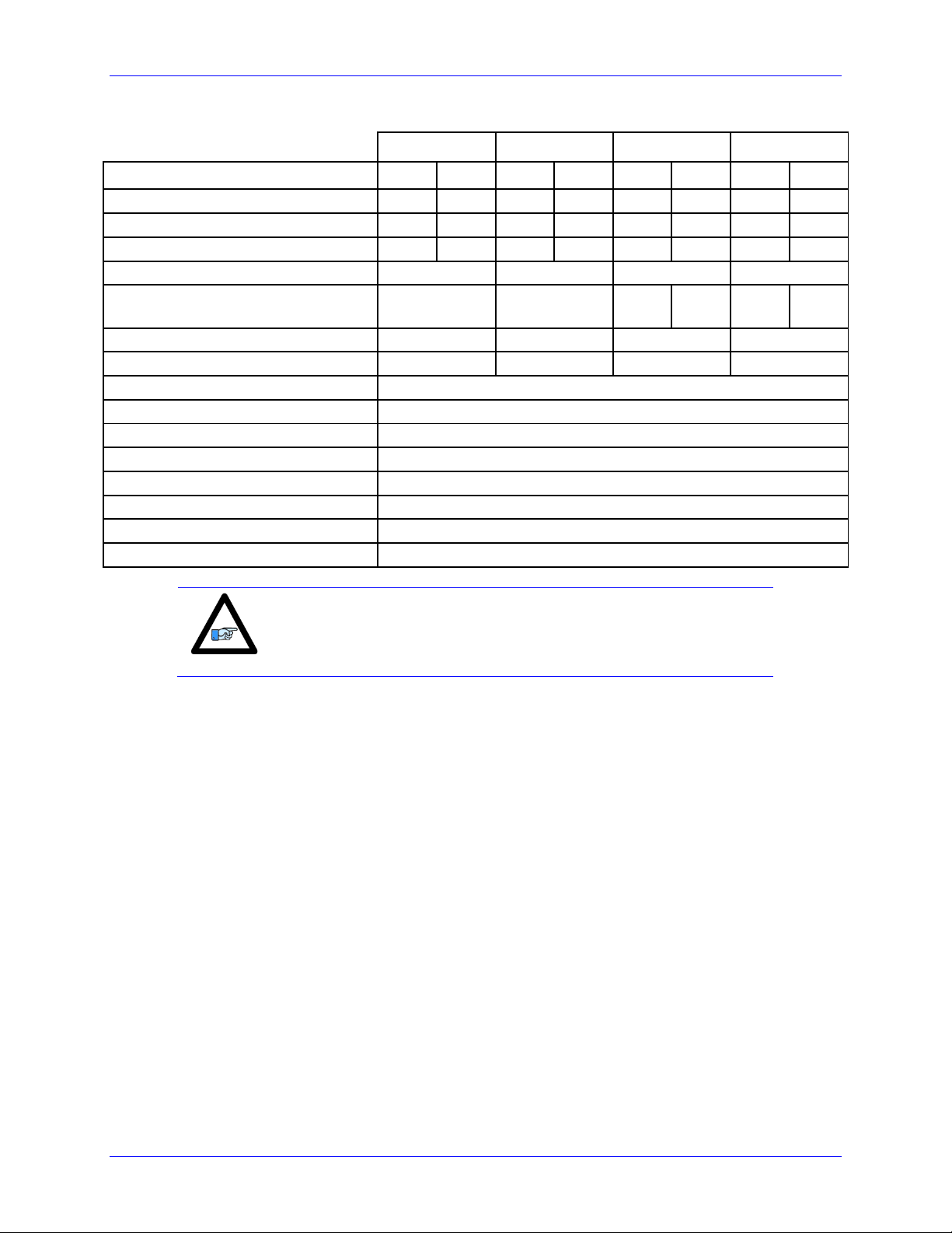
Description
Specifications
Operating Temperature
0 to 45°C
Above 40°C,de-rate current output by 2.5% per °C
Storage Temperature
-25°C to +70°C
Humidity
10% to 90% non-condensing
Operating Altitude
~3300 Feet (1000 m)
De-rate current output by 1.1% per additional 330 feet (100m)
Air Flow Clearances
~3 inches (76.2mm) above and below unit for air flow
Operating Environment
Pollution Degree 2 or equivalent
Caution
The internal I2T applies to and protects the amplifier power blocks.
The software I2T (described in later section) has to be configured
properly to protect against motor/equipment damage.
Description
Specifications
Over Voltage
~ 283 VAC / 400 VDC
Under Voltage
~ 87 VAC / 123 VDC
Over Temperature
~ 80C
Motor Short Circuit
500 % of rated peak Amps per axis
Over Current
110 % over rated peak Amps per axis
AC Input Phase Loss Detection
Loss of one or more phases (3 Phase operation only)
Shunt Fault Detection
Integrated, I2T model
Internal I2T protection
2 seconds at peak rated Amps (RMS) per axis
Note
The under voltage fault triggers when the AC Input dips below 87
VAC. However, if this threshold has not been reached (i.e. Low
Voltage/DC operation) the under voltage logic remains unarmed.
Description
Specifications
UL
UL508C File E307874
cUL
CSA C22.2 No. 14-05 File E307874
Environmental Specifications
Protection Specifications
Agency Approvals
Specifications 17
Page 18

Geo Brick Drive User Manual
4-Axis Geo Brick Drive
GBL4-xx-5xx-xxx xxxxx
GBL4-xx-8xx-xxx xxxxx
Output Continuous Current (rms/axis)
5A
8A
Output Peak Current for 2 seconds (rms/axis)
10A
16A
Rated Input Current @240VAC 3-phase(all axes)
13A
21A
Max ADC (I2T Settings)
16.26A
26.02A
Output Power Per Axis [Watts]
(Modulation depth of 60% RMS)
Output Power Total [Watts]
1247W
1995W
4988W
7980W
Power Dissipation [Watts]
498W
798W
PWM Frequency Operating Range [KHz]
1 – 18
AC Input Line Voltage [VAC rms]
110
-20%
– 240
+10%
(~87 -- 264)
DC Input Line Voltage [VDC]- DC operation
12VDC to 340VDC
Logic Power [VDC, A]
24VDC ±5%, 4A
Continuous Shunt Power rating [Watts]
5000W
Peak Shunt Power rating [Watts]
10000W
Recommended Shunt Resistor [Ohms]
GAR15 (15Ω)
Recommended Shunt Power Rating [Watts]
300W
6-Axis Geo Brick Drive
GBL6-xx-5xx-xxx xxxxx
GBL6-xx-8xx-xxx xxxxx
Axes
1-4
5-6
1-4
5-6
Output Continuous Current (rms/axis)
5A
15A
8A
15A
Output Peak Current for 2 seconds (rms/axis)
10A
30A
16A
30A
Max ADC (I2T Settings)
16.26A
48.8A
26.02A
48.8A
Rated Input Current @240VAC 3-phase(all axes)
33A
41A
Output Power Per Axis
(Modulation depth of 60% RMS)
Output Power Total
1247 W
3741 W
1995
3741
12470W
15462W
Power Dissipation [Watts]
1247W
1546W
PWM Frequency Operating Range [KHz]
1 – 18
AC Input Line Voltage [VAC rms]
110
-20%
– 240
+10%
(~87 -- 264)
DC Input Line Voltage [VDC]- DC operation
12VDC to 340VDC
Logic Power [VDC, A]
24VDC ±5%, 4A
Continuous Shunt Power rating [Watts]
7500W
Peak Shunt Power rating [Watts]
15000W
Recommended Shunt Resistor [Ohms]
GAR 10 (10 Ω)
Recommended Shunt Power Rating [Watts]
300W
Electrical Specifications
Specifications 18
Page 19
Geo Brick Drive User Manual
8-Axis Geo Brick Drive
GBL8-xx-552
GBL8-xx-882
GBL8-xx-582
GBL8-xx-852
Axes
1-4
5-8
1-4
5-8
1-4
5-8
1-4
5-8
Output Continuous Current (rms/axis)
5A
5A
8A
8A
5A
8A
8A
5A
Output Peak Current for 2 sec (rms/axis)
10A
10A
16A
16A
10A
16A
16A
10A
Max ADC (I2T Settings)
16.26A
16.26A
26.02A
26.02A
16.02A
26.02A
26.02A
16.02A
Rated Input Current @240 3-phase(all axes)
26A
42A
34A
34A
Output Power Per Axis
(Modulation depth 60% RMS)
1247W
1995W
1247W
1995W
1995W
1247W
Output Power Total
9976W
15960W
12968W
12968W
Power Dissipation
998W
1596W
1297W
1297W
PWM Frequency Operating Range [KHz]
1 – 18
AC Input Line Voltage [VAC]
110
-20%
– 240
+10%
(~87 -- 264)
DC Input Line Voltage [VDC]- DC operation
12VDC to 340VDC
Logic Power
24VDC ±5%, 4A
Continuous Shunt Power [Watts]
5000W
Peak Shunt Power rating [Watts]
10000W
Recommended Shunt Resistor [Ohms]
GAR 15 (15 Ω)
Recommended Shunt Power Rating [Watts]
300W
Note
Electrical specifications are specified for three-phase AC bus power.
De-rating applies in single-phase AC, or DC Operation.
Specifications 19
Page 20

Geo Brick Drive User Manual
RECEIVING AND UNPACKING
Delta Tau products are thoroughly tested at the factory and carefully packaged for shipment. When the
Geo Brick Drive is received, there are several things to be done immediately:
Observe the condition of the shipping container and report any damage immediately to the
commercial carrier that delivered the drive.
Remove the drive from the shipping container and remove all packing materials. Check all shipping
material for connector kits, documentation, or other small pieces of equipment. Be aware that some
connector kits and other equipment pieces may be quite small and can be accidentally discarded if
care is not used when unpacking the equipment. The container and packing materials may be retained
for future shipment.
Verify that the part number of the drive received is the same as the part number listed on the purchase
order.
Inspect the drive for external physical damage that may have been sustained during shipment and
report any damage immediately to the commercial carrier that delivered the drive.
Electronic components in this product are design-hardened to reduce static sensitivity. However, use
proper procedures when handling the equipment.
If the Geo Brick Drive is to be stored for several weeks before use, be sure that it is stored in a
location that conforms to published storage humidity and temperature specifications.
Use of Equipment
The following restrictions will ensure the proper use of the Geo Brick Drive:
The components built into electrical equipment or machines can be used only as integral components
of such equipment.
The Geo Brick Drive must not be operated on power supply networks without a ground or with an
asymmetrical ground.
If the Geo Brick Drive is used in residential areas, or in business or commercial premises, implement
additional filtering measures.
The Geo Brick Drive may be operated only in a closed switchgear cabinet, taking into account the
ambient conditions defined in the environmental specifications.
Delta Tau guarantees the conformance of the Geo Brick Drives with the standards for industrial areas
stated in this manual, only if Delta Tau components (cables, controllers, etc.) are used.
Receiving and Unpacking 20
Page 21

Geo Brick Drive User Manual
Caution
Unit must be installed in an enclosure that meets the environmental IP
rating of the end product (ventilation or cooling may be necessary to
prevent enclosure ambient from exceeding 45° C [113° F]).
MOUNTING
The location of the Geo Brick Drive is important. Installation should be in an area that is protected from
direct sunlight, corrosives, harmful gases or liquids, dust, metallic particles, and other contaminants.
Exposure to these can reduce the operating life and degrade performance of the drive.
Several other factors should be carefully evaluated when selecting a location for installation:
For effective cooling and maintenance, the Geo Brick Drive should be mounted on a smooth,
non- flammable vertical surface.
At least 76 mm (3 inches) top and bottom clearance must be provided for air flow. At least 10
mm (0.4 inches) clearance is required between units (each side).
Temperature, humidity and Vibration specifications should also be taken in account.
The Geo Brick Drive can be mounted with a traditional 4-hole panel mount, two U shape/notches on the
bottom and two pear shaped holes on top.
If multiple Geo Brick Drives are used, they can be mounted side-by-side, leaving at least a 122 mm
clearance between drives. This means a 122 mm center-to-center distance (0.4 inches) with the 4-axis
Drives. 8- and 6-axis Geo Brick Drives can be mounted side by side at 214 mm center-to-center distance
(8.4 inches). It is extremely important that the airflow is not obstructed by the placement of conduit tracks
or other devices in the enclosure.
If the drive is mounted to a back panel, the back panel should be unpainted and electrically conductive to
allow for reduced electrical noise interference. The back panel should be machined to accept the
mounting bolt pattern of the drive.
The Geo Brick Drive can be mounted to the back panel using four M4 screws and internal-tooth lock
washers. It is important that the teeth break through any anodization on the drive’s mounting gears to
provide a good electrically conductive path in as many places as possible. Mount the drive on the back
panel so there is airflow at both the top and bottom areas of the drive (at least three inches).
Mounting 21
Page 22
Geo Brick Drive User Manual
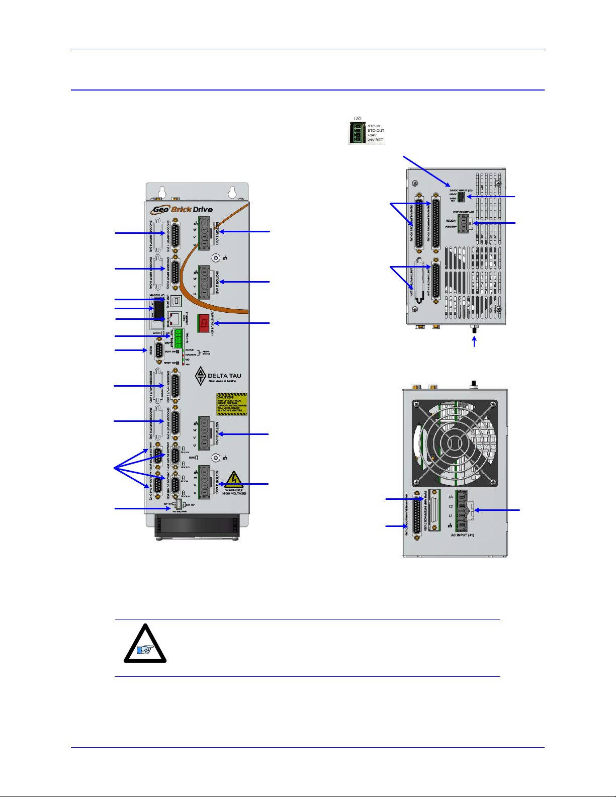
Motor #1
Motor #2
Motor #3
Motor #4
Status
Display
Alt. Enc. Pwr
Encoder #4
Encoder #3
Encoder #2
Encoder #1
USB
Ethernet
MACRO
Abort & WD
RS232
Analog I/O
Front View
Top View
24VDC
Logic Power
Shunt
Resitor
Motor Shield
Connection
General
Purpose I/O
Limits
& Flags
New Connector
(October 2012)
AC/DC
Bus Power
Input
PWM Interface
Analog I/O
Handwheel
Bottom View
Note
Newer models of the Geo Brick Drive were introduced in October of
2012. They can be recognized by the 4-pin terminal block logic and
STO connector.
Connector Locations
Mounting 22
Page 23
Geo Brick Drive User Manual
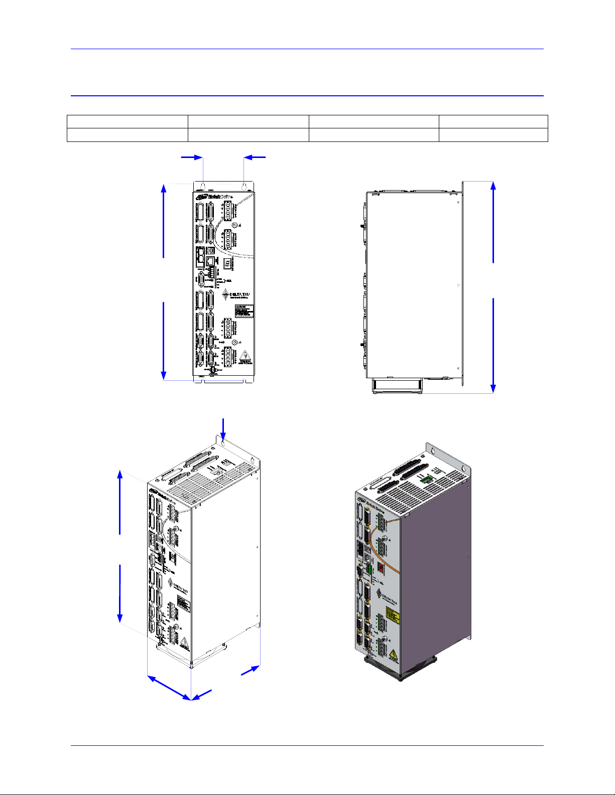
Width
Depth
Height
Weight
114mm/4.50in
178mm/7.00in
391mm/15.40in
4.4Kg/9.6lbs
3.00"
(76.20 mm)
14.31"
(363.52 mm)
15.40"
(391.16 mm)
13.38"
(339.73 mm)
4.50"
(114.29 mm)
7.00"
(177.83 mm)
4 x M4
4-Axis Geo Brick Drive
GBL4-xx-5xx-xxx-xxxx And GBL4-xx-8xx-xxx-xxxx
Mounting 23
Page 24

Geo Brick Drive User Manual
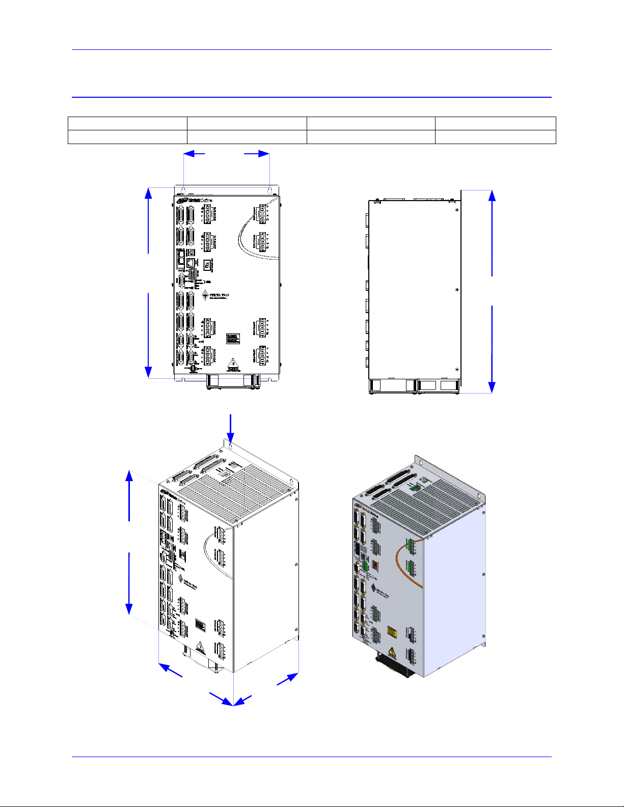
Width
Depth
Height
Weight
203mm/8.00in
178mm/7.00in
391mm/15.40in
13.38"
(339.73 mm)
8.00"
(203.20 mm)
7.00"
(177.83 mm)
4 x M4
6.50"
(165.10 mm)
14.31"
(363.52 mm)
15.40"
(391.16 mm)
6-Axis Geo Brick Drive
GBL6-xx-5xx-xxx-xxxx And GBL6-xx-8xx-xxx-xxxx
Mounting 24
Page 25
Geo Brick Drive User Manual
Width
Depth
Height
Weight
203mm/8.00in
178mm/7.00in
392mm/15.40in
9.0 Kg/19.9lbs
13.38"
(339.73 mm)
8.00"
(203.20 mm)
7.00"
(177.83 mm)
4 x M4
6.50"
(165.10 mm)
14.31"
(363.52 mm)
15.40"
(391.16 mm)
8-Axis Geo Brick Drive
GBL8-xx-552-xxx-xxxx, GBL8-xx-582-xxx-xxxx, GBL8-xx-852-xxx-xxxx, GBL8-xx-882-xxx-xxxx
Mounting 25
Page 26
Geo Brick Drive User Manual
WARNING
Installation of electrical equipment is subject to many regulations
including national, state, local, and industry guidelines and rules.
The following are general recommendations but it is important
that the integration be carried out in accordance with all
regulations pertaining to the installation.
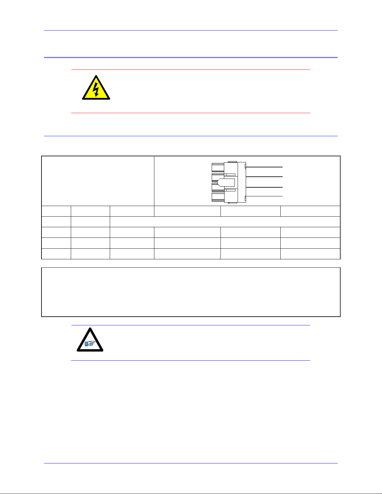
J1: Molex 4-pin Male
Mating: Molex 4-pin Female
L3
L2
L1
GND
Pin #
Symbol
Function
Three Phase
Single Phase
DC
1
GND
Ground
2
L1
Input
AC Line Phase 1
Not Connected
Not Connected
3
L2
Input
AC Line Phase 2
Neutral
DC- Return
4
L3
Input
AC Line Phase 3
Line
DC+
Molex Mating Connector p/n: 0428160412
Molex Pins p/n : 0428150031
Molex Crimper Tool p/n: 63811-1500
Delta Tau Mating Connector p/n: 014-H00F04-049 (for internal use)
Delta Tau Pins p/n: 014-042815-031 (for internal use)
Note
In single phase operation, use L2 and L3, and leave L1 floating.
In DC mode operation, use L3 for DC+ and L2 for DC return, and
leave L1 floating.
PINOUTS AND SOFTWARE SETUP
J1: Main Bus Power Input
J1 is used to bring the main AC/DC bus power into the Geo Brick Drive.
Pinouts and Software Setup 26
Page 27

Geo Brick Drive User Manual
Caution
The main bus power should NEVER be applied if the 24V logic
power is NOT applied.
Caution
Make sure that no motor commands (e.g. phasing, jogging, or open
loop) are being executed by or sent repeatedly to the controller
(PMAC) at the time of applying main bus power.
Caution
Main bus power should NEVER be applied or cycled if the 24V logic
power is NOT applied.
Power On/Off Sequence
Powering up a Geo Brick Drive must obey the following procedure:
1. Apply 24V logic power
2. Wait a minimum of ~3 seconds
3. Apply main bus power
Powering down a Geo Brick Drive must obey the following procedure:
1. Disconnect main bus power
2. Wait a minimum of ~5 seconds
3. Disconnect 24V logic power
Cycling Main Bus Power
Newer and older Geo Brick Drives differ in the delay restrictions between main power cycles.
The newer models were introduced in October of 2012. They can be recognized by the 4-pin
terminal block 24V logic with STO connector.
The older models carry the Molex type 2-pin 24V logic connector
Pinouts and Software Setup 27
Page 28
Geo Brick Drive User Manual
Caution
With older models, it is strongly advised NOT to cycle main bus
power frequently and rapidly within a few seconds.
Caution
Older models of the 4-axis Geo Brick Drives’ main bus power should not be recycled in
less than ~ 3 minutes.
Older models of the 6- and 8-axis Geo Brick Drives’ main bus power should not be
recycled in less than ~ 6 minutes.
Note
With the older models of the 6-axis Geo Brick Drives it is possible to
wire the external shunt resistor as a bleeding resistor to avoid the
extended downtime delay. Contact Delta Tau for details.
Caution
Newer models of the 4-axis Geo Brick Drives’ main bus power should not be recycled in
less than ~ 5 seconds.
Newer models of the 6- and 8-axis Geo Brick Drives’ main bus power should not be
recycled in less than ~ 10 seconds.
Note
The addition of an external shunt resistor (e.g. GAR15 or GAR10)
makes the residual power dissipation even faster.
Note
A red LED indicator, labeled “BUS”, on the front of the Geo Brick
Drive is illuminated when main bus power is applied.
Older Models of the Geo Brick Drive
With the older models of the Geo Brick Drives, cycling main bus power must obey the following warning
restrictions. A delay should be inserted in either software, hardware or both to ensure that these
restrictions are conformed.
With main bus power of 110 – 240VAC (single or three-phase):
Newer Models of the Geo Brick Drive
The newer models of the Geo Brick Drive are fitted with an internal shunt resistor (300W, 100-Ohm)
which is also used as a bleeding resistor when the main bus power is removed. This allows a rapid
discharge of the capacitors’ residual power, and shorter delay restrictions between main bus power cycles.
With main bus power of 110 – 240VAC (single or three-phase), and without an external shunt resistor,
the following delay restrictions are strongly advised:
Pinouts and Software Setup 28
Page 29

Geo Brick Drive User Manual
Caution
Main bus power lines should run in a separate duct (at least 12” or 30
cm away) from and should never be bundled with the I/O signal,
communication, or encoder cables.
Recommended Main Bus Power Wiring/Protection
Grounding, Bonding
System grounding is crucial for proper performance of the Geo Brick Drive. Panel wiring requires that a
central earth-ground (also known as ground bus bar) location be installed at one part of the panel. The
ground bus bar is usually a copper plate directly bonded to the back panel. This electrical ground
connection allows for each device within the enclosure to have a separate wire brought back to the central
earth-ground.
Implement a star point ground connection scheme; so that each device wired to earth ground
has its own conductor brought directly back to the central earth ground plate (bus bar).
Use an unpainted back panel. This allows a wide area of contact for all metallic surfaces,
reducing frequency impedances.
Use a heavy gauge ground earth conductors made up of many strands of fine conducts.
The Geo Brick Drive is brought to the earth-ground via one or two wire(s) connected to the
M4 mounting stud(s) through a heavy gauge multi-strand conductor to the central earthground.
Pinouts and Software Setup 29
Page 30
Geo Brick Drive User Manual
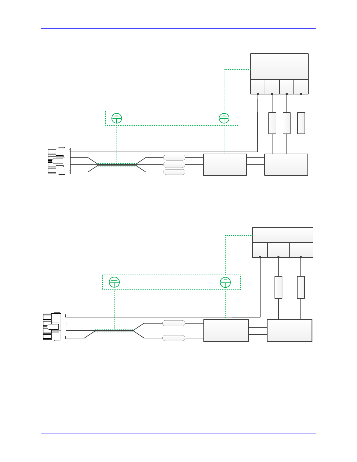
Three-Phase Main AC Power Wiring Diagram
3-PHASE
TRANSFORMER
110-240 VAC
GND L1 L2 L3
PROTECTION EARTH
FUSE
FUSE
FUSE
MAGNETIC
CONTACTOR
L1
L2
L3
GND
Shielded
And
Twisted
EMC/EMI
FILTER
Phase-Phase
Voltage
Suppressors
Single-Phase Main AC Power Wiring Diagram
GND
Neutral
Line
PROTECTION EARTH
FUSE
FUSE
MAGNETIC
CONTACTOR
L2
L3
GND
Shielded
And
Twisted
EMC/EMI
FILTER
Phase-Phase
Voltage
Suppressors
Single Phase Source
110-240 VAC
Pinouts and Software Setup 30
Page 31

Geo Brick Drive User Manual
Note
A line reactor should be installed if a transformer or reliable source of
power is not available. Line reactors suppress harmonics bidirectionally, eliminating low frequency spikes.
Model
Fuse (amps)
Model
Fuse (amps)
GBL4-xx-5xx
15
GBL8-xx-552
30
GBL4-xx-8xx
25
GBL8-xx-882
45
GBL6-xx-5xx
35
GBL8-xx-582
35
GBL6-xx-8xx
45
GBL8-xx-852
35
DC Bus Voltage:
[VDC]
Motor Phase voltage:
[VDC]
Power per axis:
[Watts]
Total power:
[Watts]
Dissipated power:
[Watts]
Current draw per phase
(for 3 bus input)
[Amps]
Current draw per phase
(for 1 bus input)
[Amps]
Transformers
Y-Y or Y- transformers should be used.
- Transformers are NOT advised. They try to balance phases dynamically, creating instances of
instability in the Geo Brick Drive’s rectifying circuitry.
Fuses
High peak currents and high inrush currents demand the use of slow blow time delayed type fuses.
RK1 or RK5 (i.e. current limiting) classes are recommended. FRN-R and LPN-RK from Cooper
Bussmann or similar fuses can be used.
The following table summarizes fuse gauges for three-phase bus input (240VAC) at full load:
Specific applications fuse sizing can be done using the following equations.
Take, as an example, a 4-axis Geo Brick (5/10A) on 240VAC bus, and driving 4 motors (5A continuous
current rating):
Thus, 15 and 25 –amp fuses are chosen for three and single phase bus power input lines respectively.
Pinouts and Software Setup 31
Page 32

Geo Brick Drive User Manual
Model
Wire Gauge
(AWG)
Model
Wire Gauge
(AWG)
GBL4-xx-5xx
12
GBL8-xx-552
10
GBL4-xx-8xx
10
GBL8-xx-882
8
GBL6-xx-5xx
8
GBL8-xx-582
8
GBL6-xx-8xx
8
GBL8-xx-852
8
Note
All ground conductors should be 8AWG minimum using wires
constructed of many strands of small gauge wire. This ensures the
lowest impedance to high-frequency noises.
Magnetic Contactors
SC-E series from Fuji Electric or similar contactor can be used.
Line Filters
Line filters eliminate electromagnetic noise in a bi-directional manner (from and into the system).
T type filters are NOT recommended. PI type line filters are highly advised:
Filter should be mounted on the same panel as the drive and power source.
Filter should be mounted as close as possible to the power source.
Filter should be mounted as close as possible to incoming cabinet power.
FN-258 series from Schaffner or similar filter can be used.
Voltage Suppressors
Voltage suppressors eliminate undesirable voltage spikes typically generated by the magnetic contactor or
external machinery in the plant.
This 3-phase voltage arrester from Phoenix Contact or similar suppressor can be used.
Bus Power Cables
The Geo Brick Drive electronics create a DC bus by rectifying the incoming AC lines. The current flow
into the drive is not sinusoidal but rather a series of narrow, high-peak pulses. Keeping the incoming
impedance small is essential for not hindering these current pulses.
Whether single- or three-phase, it is important that the AC input wires be twisted together to eliminate
noise radiation as much as possible. Recommended wire gauge:
Pinouts and Software Setup 32
Page 33

Geo Brick Drive User Manual
Note
The Safe Torque Off (STO) feature is not available with older models
of the Geo Brick Drive.
Note
The logic and STO connections can be made using a 22 gauge (AWG)
wire.
J2: 24VDC Logic Power and Safe Torque Off (STO)
J2 is used to bring the 24VDC logic power into the Geo Brick Drive. This power can remain on,
regardless of the main AC/DC bus power input, allowing the digital control electronics to be active while
the main motor power control is passive.
J2, in the newer models of the Geo Brick Drive, is also used to wire the Safe Torque Off (STO) input.
The STO allows the complete (hardware) disconnection of the power amplifiers from the motors. This
mechanism prevents unintentional “movement of” or torque output to the motors in accordance with
IEC/EN safety standards.
Newer and older models of the Geo Brick Drive have different 24V logic power connector. The new
connector is a 4-pin (as opposed to the older 2-pin) accommodating the STO function. It is a Phoenix
Contact terminal block (as opposed to the older Molex type) which allows for easier connection without
the need of special crimping tools:
The newer models were introduced in October of 2012. They can be recognized by the 4-pin
terminal block 24V logic with STO connector.
The older models carry the Molex type 2-pin 24V logic connector (no STO).
It is recommended to use a protected power supply. In situations where the power supply is shared with
other devices, it may be desirable to insert a filter before applying it to the Geo Brick Drive.
If multiple drives are driven out of the same 24VDC power supply, it is recommended that each Geo
Brick Drive be wired back to the power supply terminals independently. It is also recommended that the
power supply be sized to handle the instantaneous inrush current required to start up the DC-to-DC
converter action inside the Drive(s). See electrical specifications.
Pinouts and Software Setup 33
Page 34

Geo Brick Drive User Manual
J2: Molex 2-pin Female
Mating: Molex 2-pin Male
GND
+24VDC
Molex Mating Connector p/n: 0436450200
Molex Pins p/n: 0430300008
Molex Crimper Tool p/n: 11-01-0185
Delta Tau Mating Connector p/n: 014-043645-200 (for internal use)
Delta Tau pins p/n: 014-043030-008 (for internal use)
Pin #
Symbol
Function
Description
Notes
1
24VDC RET
Common
Logic power return
Control power return
2
+24VDC
Input
Logic power input
±5 %
J2: Phoenix TB 4-pin Female
Mating: Phoenix TB 4-pin Male
4
3
2
1
4
3
2
1
Phoenix Contact Mating Connector p/n: 1850686
Delta Tau Mating Connector p/n: (for internal use)
Pin #
Symbol
Function
Description
Notes
1
STO IN
Input
STO input
STO trigger
2
STO OUT
Output
STO feedback
STO state
3
+24VDC
Input
Logic power input
±5 %
4
24VDC RET
Common
Logic power return
Control power return
Older Models
Newer Models
Pinouts and Software Setup 34
Page 35

Geo Brick Drive User Manual
24 VDC
Power Supply
J2
+24V
24V RETCOM
+24 VDC
STO OUT
STO IN
1
2
3
4
24 VDC
Power Supply
J2
+24V
24V RETCOM
+24 VDC
STO OUT
STO IN
1
2
3
4
N.C
Input to Brick/Logic
Note
If the STO fault condition has been removed (wired properly), the
AF2 fault display can be cleared with the AMPCLRF command.
Disabling the STO (Backward compatibility)
Disabling the STO maintains full backward compatibility with existing systems, pre-STO installations.
This is done by simply tying STO IN (pin #1) to +24V (pin #3):
Wiring and Using the STO
In normal mode operation, the STO relay must be normally closed. +24V must be applied to STO
IN (pin #1) to allow power to the motors.
The STO is triggered, and power is disconnected from the motors, if the +24V is disconnected
from STO IN (pin #1).
In this mode, the Drive will display an AF2 fault on the 7-sgment display.
The STO OUT (pin #2) is a voltage status output rated to 24V ±5% at a max of 125mA. It
reflects the status of the STO function. It can be brought into a general purpose input or
to external safety logic.
(24V) in normal mode operation (+24V applied to STO IN)
(0 V) in triggered mode (+24V no applied to STO IN)
The STO relay can be wired in series with the E-Stop circuitry which typically disconnects the
main bus power from the system.
Pinouts and Software Setup 35
Page 36

Geo Brick Drive User Manual
Caution
All applications using Geo Brick Drives (all configurations) are
strongly advised to install an external shunt resistor.
4-, And 8-Axis Geo Brick
J3: Molex 2-pin Female
Mating: Molex 2-pin Male
Regen+
Regen-
GBL4
Pin #
Symbol
Function
1
REGEN-
Output
2
REGEN+
Output
Molex Mating Connector p/n: 0444412002
Molex Crimper tool p/n: 63811-0400
Molex Pins p/n: 0433751001
Delta Tau Mating Connector p/n: 014-000F02-HSG
Delta Tau Pins p/n: 014-043375-001
6-Axis Geo Brick
J3: Molex 3-pin Female
Mating: Molex 3-pin Male
Regen+
Regen-
Regen+
RegenCAP-
GBL4
GBL6
GBL8
1
CAP-
Bus – (do not wire)
2
REGEN-
Output
3
REGEN+
Output
Molex Mating Connector p/n: 0428160312
Molex Crimper tool p/n: 63811-1500
Molex Pins p/n: 0433751001
Delta Tau Mating Connector p/n: 014-H00F03-049
Delta Tau Pins p/n: 014-042815-001
J3: External Shunt Resistor
J3 is used to wire an external shunt resistor to expel the excess power during demanding deceleration
profiles. The GAR10 and GAR15 resistors are designed to drain excess bus energy very quickly. The 4and 8-axis Geo Brick Drives are designed for operation with external shunt resistors of 15 Ohms, 6-axis
units requiring 10 Ohms. Delta Tau provides these resistors with pre-terminated cables that plug directly
into connector J3.
Pinouts and Software Setup 36
Page 37

Geo Brick Drive User Manual
Caution
The external shunt resistors can reach temperatures of up to 200°C.
They must be mounted away from other devices and ideally near the
top of the cabinet, also ensure they are enclosed and cannot be touched
during operation or anytime they are hot. Sufficient warning labels
should be placed prominently nearby.
The black wires are for the thermostat and the white wires are
for the shunt resistor.
The shunt resistor incorporates a normally closed (N.C)
thermal overload protection thermostat that opens up when the
core temperature of the resistor exceeds 225°C (450° F). This
thermostat is accessible through the two black leads. It is
important that these two leads be wired in a safety circuit to
halt operation should the resistor temperature exceed the
specified threshold.
The external shunt resistor Ohm rating range is found so that
the minimum value limits the current to the permissible
amperage, and that the maximum value limits the bus (during
deceleration) to the permissible voltage.
Safety
Logic
Circuit
Regen+
Regen-
Hot!
Note
The shunt circuitry turn-on threshold is 385VDC (~272 VAC). The
turn-off threshold is 360VDC (~255VAC).
Note
Newer models of the Geo Brick Drive incorporate an internal shunt
resistor rated at 300W, 100-Ohms.
Note
Newer models of the Geo Brick Drive were introduced in October of
2012. They can be recognized by the 4-pin terminal block logic and
STO connector.
Pinouts and Software Setup 37
Page 38

Geo Brick Drive User Manual
Caution
To avoid machine/equipment damage and before applying power or
connecting any of the flags; make sure that your electrical
design/wiring is in accordance with the Geo Brick Drive’s part
number option for 5- or 24-volt connection
J4: D-sub DB-25F
Mating: D-sub DB-25M
1
2
3
4
5
6
7
8
9
10
11
12
13
14
15
16
17
18
19
20
21
22
23
24
25
Pin #
Symbol
Function
Description
1
USER1
Input
User Flag 1
2
MLIM1
Input
Negative Limit 1
3
FL_RT1
Input
Flag Return 1
4
USER2
Input
User Flag 2
5
MLIM2
Input
Negative Limit 2
6
FL_RT2
Input
Flag Return 2
7
USER3
Input
User Flag 3
8
MLIM3
Input
Negative Limit 3
9
FL_RT3
Input
Flag Return 3
10
USER4
Input
User Flag 4
11
MLIM4
Input
Negative Limit 4
12
FL_RT4
Input
Flag Return 4
13
GND
Common
14
PLIM1
Input
Positive Limit 1
15
HOME1
Input
Home Flag 1
16
EQU1
Output
Compare Output, EQU 1 TTL (5V) level
17
PLIM2
Input
Positive Limit 2
18
HOME2
Input
Home Flag 2
19
EQU2
Output
Compare Output, EQU 2 TTL (5V) level
20
PLIM3
Input
Positive Limit 3
21
HOME3
Input
Home Flag 3
22
EQU3
Output
Compare Output, EQU 3 TTL (5V) level
23
PLIM4
Input
Positive Limit 4
24
HOME4
Input
Home Flag 4
25
EQU4
Output
Compare Output, EQU 4 TTL (5V) level
Note
For 5V flags (internal use): Install RP39, RP43, RP47 and RP51.
1Kohm Sip, 8-pin, four independent Resistors.
For 12-24Vflags: Empty bank (Default).
J4: Limits, Flags, EQU [Axis 1- 4]
J4 is used to wire axis/channels 1 through 4 over travel limit switches, home and user flags, and EQU
output. The limits and flags can be ordered either 5V or 12-24V. The EQU output is always 5V. Per
axis/channel, there are 2 limit inputs, 2 flag inputs, and 1 EQU output:
- Positive limit. Negative limit
- Home flag. User flag
- EQU
Pinouts and Software Setup 38
Page 39

Geo Brick Drive User Manual
Caution
To avoid machine/equipment damage and before applying power or
connecting any of the flags; make sure that your electrical
design/wiring is in accordance with the Geo Brick Drive’s part
number option (5- or 24-volts)
J5: D-sub DB-25F
Mating: D-sub DB-25M
1
2
3
4
5
6
7
8
9
10
11
12
13
14
15
16
17
18
19
20
21
22
23
24
25
Pin #
Symbol
Function
Description
1
USER5
Input
User Flag 5
2
MLIM5
Input
Negative Limit 5
3
FL_RT5
Input
Flag Return 5
4
USER6
Input
User Flag 6
5
MLIM6
Input
Negative Limit 6
6
FL_RT6
Input
Flag Return 6
7
USER7
Input
User Flag 7
8
MLIM7
Input
Negative Limit 7
9
FL_RT7
Input
Flag Return 7
10
USER8
Input
User Flag 8
11
MLIM8
Input
Negative Limit 8
12
FL_RT8
Input
Flag Return 8
13
GND
Common
14
PLIM5
Input
Positive Limit 5
15
HOME5
Input
Home Flag 5
16
BEQU5
Output
Compare Output EQU 5, TTL (5V) level
17
PLIM6
Input
Positive Limit 6
18
HOME6
Input
Home Flag 6
19
BEQU6
Output
Compare Output EQU 6, TTL (5V) level
20
PLIM7
Input
Positive Limit 7
21
HOME7
Input
Home Flag 7
22
BEQU7
Output
Compare Output EQU 7, TTL (5V) level
23
PLIM8
Input
Positive Limit 8
24
HOME8
Input
Home Flag 8
25
BEQU8
Output
Compare Output EQU 8, TTL (5V) level
Note
For Delta Tau’s internal use:
For 5V flags: Install RP89, RP93, RP97 and RP101
1Kohm Sip, 8-pin, four independent Resistors.
For 12-24Vflags: Empty bank (Default).
J5: Limits, Flags, EQU [Axis 5- 8]
J5 is used to wire axis/channels 5 through 8 over travel limit switches, home, user flags, and EQU output.
The limits and flags can be ordered either 5V or 12-24V. The EQU output is always 5V. Per axis/channel,
there are 2 limit inputs, 2 flag inputs, and 1 EQU output:
- Positive limit. Negative limit
- Home flag. User flag
- EQU
Pinouts and Software Setup 39
Page 40

Geo Brick Drive User Manual
Sourcing Limits And Flags
Sinking Limits And Flags
12345678910111213
141516171819202122232425
5 or 24 VDC
Power supply
USER 1/5
NC POS. LIMIT 1/5
NC NEG. LIMIT 1/5
HOME 1/5
USER 2/6
NC POS. LIMIT 2/6
NC NEG. LIMIT 2/6
HOME 2/6
USER 3/7
NC POS. LIMIT 3/7
NC NEG. LIMIT 3/7
HOME 3/7
USER 4/8
NC POS. LIMIT 4/8
NC NEG. LIMIT 4/8
HOME 4/8
EQU 1/5
EQU 2/6
EQU 3/7
EQU 4/8
COM
+5VDC /
+24VDC
FLAG RETURN 1/5
FLAG RETURN 2/6
FLAG RETURN 3/7
FLAG RETURN 4/8
Note
Per channel, the flags can be either sinking or sourcing depending on
the flag return wiring. The over travel limits must be normally closed
switches. They can be disabled (Ixx24) but they are not software
configurable.
Wiring the Limits and Flags
The Geo Brick Drive’s limits and flags can be wired to be either sinking or sourcing. The opto-isolator IC
used is a PS2705-4NEC-ND quad phototransistor output type. This IC allows the current to flow from
return to flag or from flag to return. Sinking into or sourcing out of the Geo Brick Drive:
Pinouts and Software Setup 40
Page 41

Geo Brick Drive User Manual
Limits and Flags [Axis 1- 4] Suggested M-Variables
M115->X:$078000,19 ; User 1 flag input status
M116->X:$078000,9 ; EQU1, ENC1 compare output value
M120->X:$078000,16 ; Home flag 1 input status
M121->X:$078000,17 ; Positive Limit 1 flag input status
M122->X:$078000,18 ; Negative Limit 1 flag input status
M215->X:$078008,19 ; User 2 flag input status
M216->X:$078008,9 ; EQU2, ENC2 compare output value
M220->X:$078008,16 ; Home flag 2 input status
M221->X:$078008,17 ; Positive Limit 2 flag input status
M222->X:$078008,18 ; Negative Limit 2 flag input status
M315->X:$078010,19 ; User 3 flag input status
M316->X:$078010,9 ; EQU3, ENC3 compare output value
M320->X:$078010,16 ; Home flag 3 input status
M321->X:$078010,17 ; Positive Limit 3 flag input status
M322->X:$078010,18 ; Negative Limit 3 flag input status
M415->X:$078018,19 ; User 4 flag input status
M416->X:$078018,9 ; EQU4, ENC4 compare output value
M420->X:$078018,16 ; Home flag 4 input status
M421->X:$078018,17 ; Positive Limit 4 flag input status
M422->X:$078018,18 ; Negative Limit 4 flag input status
Limits and Flags [Axis 5- 8] Suggested M-Variables
M515->X:$078100,19 ; User 5 flag input status
M516->X:$078100,9 ; EQU5, ENC5 compare output value
M520->X:$078100,16 ; Home flag 5 input status
M521->X:$078100,17 ; Positive Limit 5 flag input status
M522->X:$078100,18 ; Negative Limit 5 flag input status
M615->X:$078108,19 ; User 6 flag input status
M616->X:$078108,9 ; EQU6, ENC6 compare output value
M620->X:$078108,16 ; Home flag 6 input status
M621->X:$078108,17 ; Positive Limit 6 flag input status
M622->X:$078108,18 ; Negative Limit 6 flag input status
M715->X:$078110,19 ; User 7 flag input status
M716->X:$078110,9 ; EQU7, ENC7 compare output value
M720->X:$078110,16 ; Home flag 7 input status
M721->X:$078110,17 ; Positive Limit 7 flag input status
M722->X:$078110,18 ; Negative Limit 7 flag input status
M815->X:$078118,19 ; User 8 flag input status
M816->X:$078118,9 ; EQU8, ENC4 compare output value
M820->X:$078118,16 ; Home flag 8 input status
M821->X:$078118,17 ; Positive Limit 8 flag input status
M822->X:$078118,18 ; Negative Limit 8 flag input status
Pinouts and Software Setup 41
Page 42

Geo Brick Drive User Manual
J6: D-sub DC-37F
Mating: D-sub DC-37M
12345678910111213
202122232425262728293031
141516171819
323334353637
Pin #
Symbol
Function
Description
1
GPI1
Input
Input 1 2 GPI3
Input
Input 3
3
GPI5
Input
Input 5 4 GPI7
Input
Input 7 5 GPI9
Input
Input 9 6 GPI11
Input
Input 11 7 GPI13
Input
Input 13 8 GPI15
Input
Input 15
9
IN_COM1-8
Common 01-08
Input 01 to 08 Common
10
OUT-RET
Input
Outputs Return
11
OUT_COM
Input
Outputs Common
12
GP01-
Output
Sourcing Output 1
13
GP02-
Output
Sourcing Output 2
14
GP03-
Output
Sourcing Output 3
15
GP04-
Output
Sourcing Output 4
16
GP05-
Output
Sourcing Output 5
17
GP06-
Output
Sourcing Output 6
18
GP07-
Output
Sourcing Output 7
19
GP08-
Output
Sourcing Output 8
20
GPI2
Input
Input 2
21
GPI4
Input
Input 4
22
GPI6
Input
Input 6
23
GPI8
Input
Input 8
24
GPI10
Input
Input 10
25
GPI12
Input
Input 12
26
GPI14
Input
Input 14
27
GPI16
Input
Input 16
28
IN_COM9-16
Common 09-16
Input 09 to 16 Common
29
OUT_COM
Input
Outputs Common
30
GP01+
Output
Sinking Output 1
31
GP02+
Output
Sinking Output 2
32
GP03+
Output
Sinking Output 3
33
GP04+
Output
Sinking Output 4
34
GP05+
Output
Sinking Output 5
35
GP06+
Output
Sinking Output 6
36
GP07+
Output
Sinking Output 7
37
GP08+
Output
Sinking Output 8
J6: General Purpose Inputs/Outputs
J6 is used to wire general purpose digital inputs/outputs to the Geo Brick Drive.
Pinouts and Software Setup 42
Page 43

Geo Brick Drive User Manual
J7: D-sub DC-37F
Mating: D-sub DC-37M
12345678910111213
202122232425262728293031
141516171819
323334353637
Pin #
Symbol
Function
Description
1
GPI17
Input
Input 17 2 GPI19
Input
Input 19
3
GPI21
Input
Input 21 4 GPI23
Input
Input 23 5 GPI25
Input
Input 25 6 GPI27
Input
Input 27 7 GPI29
Input
Input 29 8 GPI31
Input
Input 31
9
IN_COM 17-24
Common 17-24
Input 17 to 24 Common
10
OUT-RET
Input
Outputs Return
11
OUT_COM
Input
Outputs Common
12
GPO9-
Output
Sourcing Output 9
13
GPO10-
Output
Sourcing Output 10
14
GPO11-
Output
Sourcing Output 11
15
GPO12-
Output
Sourcing Output 12
16
GPO13-
Output
Sourcing Output 13
17
GPO14-
Output
Sourcing Output 14
18
GPO15-
Output
Sourcing Output 15
19
GPO16-
Output
Sourcing Output 16
20
GPI18
Input
Input 18
21
GPI20
Input
Input 20
22
GPI22
Input
Input 22
23
GPI24
Input
Input 24
24
GPI26
Input
Input 26
25
GPI28
Input
Input 28
26
GPI30
Input
Input 30
27
GPI32
Input
Input 32
28
IN_COM_25-32
Common 25-32
Input 25 to 32 Common
29
OUT_COM
Input
Outputs Common
30
GPO9+
Output
Sinking Output 9
31
GPO10+
Output
Sinking Output 10
32
GPO11+
Output
Sinking Output 11
33
GPO12+
Output
Sinking Output 12
34
GPO13+
Output
Sinking Output 13
35
GPO14+
Output
Sinking Output 14
36
GPO15+
Output
Sinking Output 15
37
GPO16+
Output
Sinking Output 16
J7: General Purpose Inputs/Outputs (Additional)
J7 is used to wire the additional (optional) general purpose digital Inputs/Outputs to the Geo Brick.
Pinouts and Software Setup 43
Page 44

Geo Brick Drive User Manual
Note
The inputs can be wired either sourcing or sinking in sets of eight,
with each set possessing its own common.
Note
Do not mix topologies for outputs. They are all either sinking or
sourcing. If the common emitter is used, the common collector should
not be connected and vice versa.
Note
Newer models of the Geo Brick Drive were introduced in October of
2012. They can be recognized by the 4-pin terminal block logic and
STO connector.
About the Digital Inputs and Outputs
All general purpose inputs and outputs are optically isolated. They operate in the 12–24 VDC range, and
can be wired to be either sinking into or sourcing from the Geo Brick Drive.
Inputs
The inputs use the PS2505L-1NEC photocoupler.
For sourcing inputs, connect the input common pin(s) to the 12–24V line of the power supply. The input
devices are then connected to the common ground line of the power supply at one end, and individual
input pins at the other.
For sinking inputs, connect the input common pin(s) to the common ground line of the power supply. The
input devices are then connected to the 12–24V line of the power supply at one end, and individual input
pins at the other.
Outputs
The outputs, in the older models of the Geo Brick Drive, use the PS2501L-1NEC photocoupler. They
are rated to a maximum current of 500 mA, and are overload protected.
The outputs, in the newer models of the Geo Brick Drive (control board 603793-10A and later), use the
PS2701-1NEC photocoupler. They are protected with a ZXMS6006DG; an enhancement mode
MOSFET - diode incorporated. The protection involves over-voltage, over-current, I2T and short circuit.
For sourcing outputs, connect the common collector (pin #29) to the 12–24V line of the power supply.
The output devices are then connected to the common ground line of the power supply at one end, and
individual sourcing output pins at the other.
For sinking outputs, connect the common emitter (pin #11) to the common ground line of the power
supply. The output devices are then connected to the 12–24V line of the power supply at one end, and
individual sinking output pins at the other.
Pinouts and Software Setup 44
Page 45

Sourcing Inputs / Outputs
Sinking Inputs / Outputs
12345678910111213
202122232425262728293031
12 - 24 VDC
Power supply
INPUT 1 / 17
INPUT 2 / 18
INPUT 3 / 19
INPUT 4 / 20
INPUT 7 / 23
INPUT 8 / 24
INPUT 9 / 25
INPUT 10 / 26
INPUT 13 / 29
INPUT 14 / 30
INPUT 15 / 31
INPUT 16 / 32
INPUT 6 / 22
INPUT 12 / 28
OUTPUT 1 / 9
COM
+12VDC /
+24VDC
141516171819
323334353637
COM. COLLECT
INPUT 5 / 21
INPUT 11 / 27
OUTPUT 2 / 10
OUTPUT 3 / 11
OUTPUT 4 / 12
OUTPUT 5 / 13
OUTPUT 6 / 14
OUTPUT 7 / 15
OUTPUT 8 / 16
IN COM 09-16 / 25-32
IN COM 01-08 / 17-24
COM. COLLECT
12345678910111213
202122232425262728293031
12 - 24 VDC
Power supply
INPUT 1 / 17
INPUT 2 / 18
INPUT 3 / 19
INPUT 4 / 20
INPUT 7 / 23
INPUT 8 / 24
INPUT 9 / 25
INPUT 10 / 26
INPUT 13 / 29
INPUT 14 / 30
INPUT 15 / 31
INPUT 16 / 32
INPUT 6 / 22
INPUT 12 / 28
OUTPUT 1 / 9
COM
+12VDC /
+24VDC
141516171819
323334353637
COM. EMIT
INPUT 5 / 21
INPUT 11 / 27
OUTPUT 2 / 10
OUTPUT 3 / 11
OUTPUT 4 / 12
OUTPUT 5 / 13
OUTPUT 6 / 14
OUTPUT 7 / 15
OUTPUT 8 / 16
IN COM 09-16 / 25-32
IN COM 01-08 / 17-24
COM. EMIT
Geo Brick Drive User Manual
Wiring the Digital Inputs and Outputs
The inputs and outputs can be wired to be either sourcing out of or sinking into the Geo Brick Drive:
Pinouts and Software Setup 45
Page 46

Geo Brick Drive User Manual
General Purpose I/Os (J6) Suggested M-Variables
// Inputs:
M1->Y:$78800,0,1 ; Input 01 J6 Pin#1
M2->Y:$78800,1,1 ; Input 02 J6 Pin#20
M3->Y:$78800,2,1 ; Input 03 J6 Pin#2
M4->Y:$78800,3,1 ; Input 04 J6 Pin#21
M5->Y:$78800,4,1 ; Input 05 J6 Pin#3
M6->Y:$78800,5,1 ; Input 06 J6 Pin#22
M7->Y:$78800,6,1 ; Input 07 J6 Pin#4
M8->Y:$78800,7,1 ; Input 08 J6 Pin#23
M9->Y:$78801,0,1 ; Input 09 J6 Pin#5
M10->Y:$78801,1,1 ; Input 10 J6 Pin#24
M11->Y:$78801,2,1 ; Input 11 J6 Pin#6
M12->Y:$78801,3,1 ; Input 12 J6 Pin#25
M13->Y:$78801,4,1 ; Input 13 J6 Pin#7
M14->Y:$78801,5,1 ; Input 14 J6 Pin#26
M15->Y:$78801,6,1 ; Input 15 J6 Pin#8
M16->Y:$78801,7,1 ; Input 16 J6 Pin#27
//Outputs: Output# Sourcing Sinking
M33->Y:$078802,0,1 ; Output 1 J6 Pin#12 Pin#30
M34->Y:$078802,1,1 ; Output 2 J6 Pin#13 Pin#31
M35->Y:$078802,2,1 ; Output 3 J6 Pin#14 Pin#32
M36->Y:$078802,3,1 ; Output 4 J6 Pin#15 Pin#33
M37->Y:$078802,4,1 ; Output 5 J6 Pin#16 Pin#34
M38->Y:$078802,5,1 ; Output 6 J6 Pin#17 Pin#35
M39->Y:$078802,6,1 ; Output 7 J6 Pin#18 Pin#36
M40->Y:$078802,7,1 ; Output 8 J6 Pin#19 Pin#37
General Purpose I/Os Additional (J7) Suggested M-Variables
// Inputs:
M17->Y:$78803,0,1 ; Input 17 J7 Pin#1
M18->Y:$78803,1,1 ; Input 18 J7 Pin#20
M19->Y:$78803,2,1 ; Input 19 J7 Pint#2
M20->Y:$78803,3,1 ; Input 20 J7 Pin#21
M21->Y:$78803,4,1 ; Input 21 J7 Pin#3
M22->Y:$78803,5,1 ; Input 22 J7 Pin#22
M23->Y:$78803,6,1 ; Input 23 J7 Pin#4
M24->Y:$78803,7,1 ; Input 24 J7 Pin#23
M25->Y:$78804,0,1 ; Input 25 J7 Pin#5
M26->Y:$78804,1,1 ; Input 26 J7 Pin#24
M27->Y:$78804,2,1 ; Input 27 J7 Pin#6
M28->Y:$78804,3,1 ; Input 28 J7 Pin#25
M29->Y:$78804,4,1 ; Input 29 J7 Pin#7
M30->Y:$78804,5,1 ; Input 30 J7 Pin#26
M31->Y:$78804,6,1 ; Input 31 J7 Pin#8
M32->Y:$78804,7,1 ; Input 32 J7 Pin#27
//Outputs: Output# Sourcing Sinking
M41->Y:$078805,0,1 ; Output 09 J7 Pin#12 Pin#30
M42->Y:$078805,1,1 ; Output 10 J7 Pin#13 Pin#31
M43->Y:$078805,2,1 ; Output 11 J7 Pin#14 Pin#32
M44->Y:$078805,3,1 ; Output 12 J7 Pin#15 Pin#33
M45->Y:$078805,4,1 ; Output 13 J7 Pin#16 Pin#34
M46->Y:$078805,5,1 ; Output 14 J7 Pin#17 Pin#35
M47->Y:$078805,6,1 ; Output 15 J7 Pin#18 Pin#36
M48->Y:$078805,7,1 ; Output 16 J7 Pin#19 Pin#37
Pinouts and Software Setup 46
Page 47

Geo Brick Drive User Manual
J8: PWM Amplifier Interface
J8 is used to connect to third party PWM amplifiers. This is a limited option, contact technical support for
setup details.
Pinouts and Software Setup 47
Page 48

Geo Brick Drive User Manual
J9: D-sub DB-25F
Mating: D-sub DB-25M
1
2
3
4
5
6
7
8
9
10
11
12
13
14
15
16
17
18
19
20
21
22
23
24
25
Pin #
Symbol
Function
Notes
1
AIN1
Input
Analog Input #1
2
AIN3
Input
Analog Input #3
3
AIN5
Input
Analog Input #5
4
AIN7
Input
Analog Input #7
5
+12V
Output
For troubleshooting (no practical use)
6
GND
Common
Common Ground
7
ANAOUT-
Output
Analog Output -
8
PULSE-
Output
Pulse Output -
9
DIR-
Output
Direction Output -
10
HWA+
Input
Handwheel Quadrature A
11
HWB+
Input
Handwheel Quadrature B
12
HWC+
Input
Handwheel Quadrature C
13
+5V
Output
For troubleshooting (no practical use)
14
AIN2
Input
Analog Input #2
15
AIN4
Input
Analog Input #4
16
AIN6
Input
Analog Input #6
17
AIN8
Input
Analog Input #8
18
-12V
Output
For troubleshooting (no practical use)
19
ANAOUT+
Output
Analog Output +
20
PULSE+
Output
Pulse Output +
21
DIR+
Output
Direction Output +
22
GND
Common
Common Ground
23
HWA-
Input
Handwheel Quadrature A/
24
HWB-
Input
Handwheel Quadrature B/
25
HWC-
Input
Handwheel Quadrature C/
Note
Analog Inputs at Y:$784B0 using PMAC option12.
Analog Output at Y:$78412,8,16,S using Supp. Ch1* Output A.
Pulse and Direction at Y:$7841C,8,16,S using Supp. Ch2* Output C.
Handwheel Input at Y:$78410 using Supp. Ch1* Handwheel.
J9: Handwheel and Analog I/O
J9 is used to wire the additional analog inputs, handwheel encoder, analog output, and PFM output.
Pinouts and Software Setup 48
Page 49

Geo Brick Drive User Manual
The J9 port can be used to bring in eight
multiplexed 12-bit single-ended analog
inputs using the traditional Option 12.
These analog inputs can be used either in
unipolar mode in the 0V to +10V range, or
bipolar mode in the -10V to +10V range.
Each input has a 470Ω input resistor inline, and a 0.01 μF resistor to ground
ensuing a 4.7 μsec time constant per input
line.
±10VDC
Input Signals
12345678910111213
141516171819202122232425
ADC3
ADC1AGND
ADC2AGND
AGND
ADC4AGND
ADC5AGND
ADC6AGND
ADC7AGND
ADC8AGND
Bipolar Mode
Unipolar Mode
I5081=$000008 ; ADC1 Bipolar
I5082=$000009 ; ADC2 Bipolar
I5083=$00000A ; ADC3 Bipolar
I5084=$00000B ; ADC4 Bipolar
I5085=$00000C ; ADC5 Bipolar
I5086=$00000D ; ADC6 Bipolar
I5087=$00000E ; ADC7 Bipolar
I5088=$00000F ; ADC8 Bipolar
I5081=$000000 ; ADC1 Unipolar
I5082=$000001 ; ADC2 Unipolar
I5083=$000002 ; ADC3 Unipolar
I5084=$000003 ; ADC4 Unipolar
I5085=$000004 ; ADC5 Unipolar
I5086=$000005 ; ADC6 Unipolar
I5087=$000006 ; ADC7 Unipolar
I5088=$000007 ; ADC8 Unipolar
Note
A SAVE and a reset ($$$) is required to initialize this function
properly after download.
Note
In Unipolar mode, the ADCs can measure up to 12V since the opamps are powered with 12VDC.
Setting up the Analog Inputs (J9)
I5060=8 ; Copy 8 ADC pairs
I5061=$000340 ; ADC1 is referenced to $078800+$000340= $78B40
I5062=$000340 ; ADC2 is referenced to $078800+$000340= $78B40
I5063=$000340 ; ADC3 is referenced to $078800+$000340= $78B40
I5064=$000340 ; ADC4 is referenced to $078800+$000340= $78B40
I5065=$000340 ; ADC5 is referenced to $078800+$000340= $78B40
I5066=$000340 ; ADC6 is referenced to $078800+$000340= $78B40
I5067=$000340 ; ADC7 is referenced to $078800+$000340= $78B40
I5068=$000340 ; ADC8 is referenced to $078800+$000340= $78B40
Pinouts and Software Setup 49
Page 50
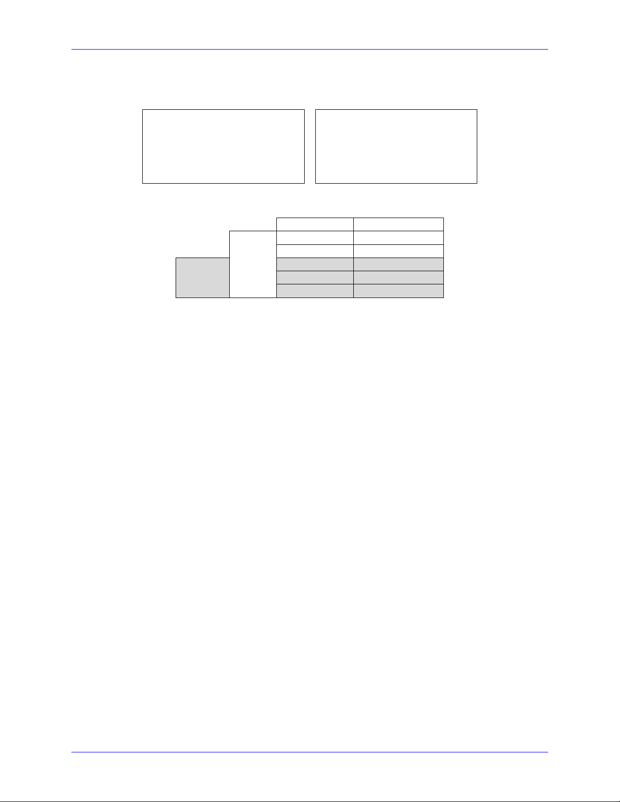
Geo Brick Drive User Manual
Bipolar Mode (Signed)
Unipolar Mode (Unsigned)
M6991->Y:$003400,12,12,S ; ADC1
M6992->Y:$003402,12,12,S ; ADC2
M6993->Y:$003404,12,12,S ; ADC3
M6994->Y:$003406,12,12,S ; ADC4
M6995->Y:$003408,12,12,S ; ADC5
M6996->Y:$00340A,12,12,S ; ADC6
M6997->Y:$00340C,12,12,S ; ADC7
M6998->Y:$00340E,12,12,S ; ADC8
M6991->Y:$003400,12,12,U ; ADC1
M6992->Y:$003402,12,12,U ; ADC2
M6993->Y:$003404,12,12,U ; ADC3
M6994->Y:$003406,12,12,U ; ADC4
M6995->Y:$003408,12,12,U ; ADC5
M6996->Y:$00340A,12,12,U ; ADC6
M6997->Y:$00340C,12,12,U ; ADC7
M6998->Y:$00340E,12,12,U ; ADC8
Input Voltage
Software Counts
Bipolar
-10
-2048
-5
-1024
Unipolar
0 0 +10
+2048
+5
+1024
J9 Analog Inputs Suggested M-Variables
Testing The J9 Analog Inputs
Pinouts and Software Setup 50
Page 51

Geo Brick Drive User Manual
Differential Output
Single-Ended Output
12345678910111213
141516171819202122232425
Analog
Device
DAC-
DAC+
DAC Output
±10VDC
12345678910111213
141516171819202122232425
DAC Output
±10VDC
Analog
Device
DAC
COM
Default Servo IC 0
Clock Settings
Resulting
Frequencies KHz
MACRO IC 0
Clock Settings
Resulting
Frequencies KHz
I7000=6527
I7001=0
I7002=3
I10=3713991
PWM
PHASE
SERVO
4.5
9
2.25
I6800=816
I6801=7
I6802=3
I6804=0
PWM
PHASE
SERVO
PWM
Deadtime
36
9
2.25
0
Servo IC 0
Clock Settings
Resulting
Frequencies KHz
MACRO IC 0
Clock Settings
Resulting
Frequencies KHz
I7000=3275
I7001=0
I7002=3
I10=1863964
PWM
PHASE
SERVO
9
18
4.5
I6800=816
I6801=3
I6802=3
I6804=0
PWM
PHASE
SERVO
PWM
Deadtime
36
18
4.5
0
Setting up the Analog Output (J9)
The analog output out of J9 is a (12-bit) filtered PWM signal, therefore a PWM frequency in the range of
30-36 KHz and a PWM deadtime of zero are suggested for a good quality analog output signal (minimum
ripple). A fully populated Brick can have one of three gates generating the clocks:
Servo IC 0
Servo IC 1
MACRO IC 0
I19 specifies which gate is the clock source master. I19 is equal to 7007 by default indicating that Servo
IC 0 is the master gate. However, the analog output on J9 is generated from MACRO IC 0.
The relationship between the PWM clock frequency of the clock-receiving gate and the clock-generating
gate should always be respected in such a way that:
Examples:
With Servo IC 0 sourcing the clock at default settings (4.5 KHz PWM), the following are suggested
MACRO IC 0 clock settings which would provide a good analog output signal:
Where n is an integer
With Servo IC 0 sourcing the clock at enhanced clock settings (9.0 KHz PWM), the following are
suggested MACRO IC 0 clock settings which would provide a good analog output signal:
Note that n=8 in this case
Note that n=4 in this case
Pinouts and Software Setup 51
Page 52

Geo Brick Drive User Manual
Note
These MACRO IC0 Clock settings are optimized for a good Analog
Output signal. If the Brick is a MACRO Ring Controller then the
analog output signal quality is compromised with a much lower PWM
frequency, or should not be used at all.
M7050
Single-Ended:
Gnd Output+
Differential:
Output+ Output-
-10V
-20V
-408
-5V
-10V
0
0V
0V
408
+5V
+10V
816
+10V
+20V
Note
Writing values greater than I6800 (i.e. 816) in M7050 will saturate the
output to 10, or 20 volts in single-ended or differential mode
respectively
Note
MACRO connectivity provides more solutions for analog outputs, e.g.
using ACC-24M2A.
For Help with clock calculations, download the Delta Tau Calculator: DT Calculator Forum Link
J9 Analog Output Suggested M-Variable
// I/O 10 & 11 Mode (PWM)
M7051->Y:$78404,10,1
M7052->Y:$78404,11,1
M7051=0 ; =0 PWM, =1 PFM
M7052=0 ; =0 PWM, =1 PFM
// Analog Output M-variable
M7050->Y:$78412,8,16,S
// These I/O nodes have to be setup once on power-up.
// power-up PLC Example
Open PLC 1 clear
I6612=100*8388608/I10 While(I6612>0) Endw
M7051=0 ; PWM mode
M7052=0 ; PWM mode
Disable PLC 1
Close
Testing the J9 Analog Output
With I6800=816, writing directly to the assigned M-variable (i.e. M7050) should produce the following:
Pinouts and Software Setup 52
Page 53

Geo Brick Drive User Manual
Differential Pulse And Direction
Single Ended Pulse And Direction
12345678910111213
141516171819202122232425
PULSE
FREQUENCY
DEVICE/
AMPLIFIER
PULSE+
PULSE-
DIR+
DIR-
12345678910111213
141516171819202122232425
PULSE
FREQUENCY
DEVICE/
AMPLIFIER
PULSE+
DIR+
COM
Step1
Step2
Results
Setting up Pulse And Direction Output PFM (J9)
Using the Delta Tau Calculator or referring to the Turbo Software Reference Manual, the desired
maximum PFM Frequency and pulse width can be chosen. DT Calculator
Step 1: Choose Max PFM clock by changing the PFM clock divider. Click on calculate to see results.
Step 2: Choose PFM Pulse width by changing I6804. Click on calculate to see results.
For a PFM clock range 0-20 KHz, and a pulse width of ~20 μsec:
I6803=2290 ; PFM Clock divider equal to 6
I6804=13 ; PFM Pulse Width Control equal to 13
Pinouts and Software Setup 53
Page 54

Geo Brick Drive User Manual
M8000
PFM [KHz]
0
0
1213
11
2427
22
The output frequency control Ixx69 specifies the maximum command output value that corresponds to the
maximum PFM Frequency.
I6826=3 ; MACRO IC Channel2 Output Mode Select. C PFM
M8000->Y:$7841C,8,16,S ; Supplementary Channel 2* Output C Command Value
; Min=0, Max= Calculated Ixx69
M8001->X:$7841D,21 ; Invert C Output Control. 0=no inversion, 1=invert
Testing The J9 PFM Output
Writing, directly to the suggested M-variable (i.e. M8000), values proportional to the calculated Ixx69,
produces the following corresponding frequencies:
Pinouts and Software Setup 54
Page 55

Geo Brick Drive User Manual
Differential Handwheel
Single ended Handwheel
12345678910111213
141516171819202122232425
Quadrature
Encoder
CHA+
CHA-
+5V PWR
GND
CHB+
CHB-
CHC+
CHC-
External +5V
Power Supply
+5V
COM
12345678910111213
141516171819202122232425
Quadrature
Encoder
CHA+
+5V PWR
GND
CHB+
CHC+
External +5V
Power Supply
+5V
COM
Setting up the Handwheel Port (J9)
A quadrature encoder type device is normally brought into the handwheel port; it can be wired and used
in either single-ended or differential mode. The encoder power is not provided for this device, it must be
brought in externally.
The encoder data can be brought into the Encoder Conversion Table allowing direct access with an Mvariable or used as a master position (Ixx05) for a specific motor.
Example:
I8000=$78410 ; ECT Entry 1: 1/T extension of location $78410
M8000->X:$3501,0,24,S ; ECT 1st entry result
Pinouts and Software Setup 55
Page 56

Geo Brick Drive User Manual
X1-X8: D-sub DA-15F
Mating: D-sub DA-15M
2
3
4
5
6
7
8
9
10
11
12
13
14
15
1
Pin#
Symbol
Function
Description
1
CHA+
Input
Encoder A+
2
CHB+
Input
Encoder B+
3
CHC+ / AENA+
Input
Encoder Index+ / Stepper amp enable +
4
ENCPWR
Output
Encoder Power 5V
5
CHU+ / DIR+
In/Out
Halls U+ / Direction Output + for Stepper
6
CHW+/ PUL+
In/Out
Halls W+ / Pulse Output + for Stepper
7
2.5V
Output
2.5V Reference power
8
Stepper Enable
Input
Tie to pin#4 (5V) to enable PFM output
9
CHA-
Input
Encoder A-
10
CHB-
Input
Encoder B-
11
CHC- / AENA-
Input
Encoder Index- / Stepper amp enable -
12
GND
Common
Common ground
13
CHV+ / DIR-
In/Out
Halls V+ / Direction Output- for Stepper
14
CHT+ / PUL-
In/Out
Halls T+ / Pulse Output- for Stepper
15 - -
Unused
Note
Use an encoder cable with high quality shield. Connect the shield to
connector shell, and use ferrite core in noise sensitive environments.
X1-X8: Encoder Feedback, Digital A Quad B
The standard encoder inputs on the Geo Brick Drive are designed for differential quadrature type signals.
Quadrature encoders provide two digital signals to determine the position of the motor. Each nominally
with 50% duty cycle, and nominally 1/4 cycle apart. This format provides four distinct states per cycle of
the signal, or per line of the encoder. The phase difference of the two signals permits the decoding
electronics to discern the direction of travel, which would not be possible with a single signal.
Pinouts and Software Setup 56
Page 57

Geo Brick Drive User Manual
Channel A
Channel B
Differential Quadrature Encoder Wiring
Single-Ended Quadrature Encoder Wiring
2
3
4
5
6
7
8
9
10
11
12
13
14
15
1
A+
A-
B-
B+
C+
C-
+ 5VDC
GND
Encoder shield (solder to shell)
U+
V+
W+
T+
Differential Quadrature Encoder
with hall sensors (optional)
2
3
4
5
6
7
8
9
10
11
12
13
14
15
1
A+
B+
C+
+ 5VDC
GND
Encoder shield (solder to shell)
U+
V+
W+
T+
Single-Ended Quadrature Encoder
with hall sensors (optional)
Note
For single-ended encoders, tie the negative pins to power reference
(Pin#7). Alternately, some open collector single ended encoders may
require tying the negative pins to ground in series with a 1-2 KOhm
resistors.
Note
Some motor manufacturers bundle the hall sensors with the motorlead cable. The hall sensors must be brought into this connector for
setup simplicity.
Typically, these signals are 5V TTL/CMOS level whether they are single-ended or differential.
Differential signals can enhance noise immunity by providing common mode noise rejection. Modern
design standards virtually mandate their use in industrial systems.
Pinouts and Software Setup 57
Page 58

Geo Brick Drive User Manual
Note
No automatic action is taken by the Geo Brick Drive if the encoder
count error bit is set.
Setting up Quadrature Encoders
Digital Quadrature Encoders use the 1/T incremental entry in the encoder conversion table. Position and
velocity pointers should, by default, be valid and in most cases no software setup is required, activating
(Ixx00=1) the corresponding channel is sufficient to see encoder counts in the position window when the
motor/encoder shaft is moved by hand.
I100,8,100=1 ; Channels 1-8 activated
Encoder Count Error (Mxx18)
The Geo Brick Drive has an encoder count error detection feature. If both the A and B channels of the
quadrature encoder change state at the decode circuitry (post-filter) in the same hardware sampling clock
(SCLK) cycle, an unrecoverable error to the counter value will result (lost counts). Suggested M-Variable
Mxx18 for this channel is then set and latched to 1 (until reset or cleared). The three most common root
causes of this error:
- Real encoder hardware problem
- Trying to move the encoder (motor) faster than it’s specification
- Using an extremely high resolution/speed encoder. This may require increasing the SCLK
The default sampling clock in the Geo Brick Drive is ~ 10MHz, which is acceptable for virtually all
applications. A setting of I7mn3 of 2257 (from default of 2258) sets the sampling clock SCLK at about
~20MHz. It can be increased to up to ~40 MHz.
Pinouts and Software Setup 58
Page 59

Geo Brick Drive User Manual
Note
Single-Ended Quadrature Encoders are not supported for encoder loss.
Ch#
Address/Definition
Ch#
Address/Definition
1 Y:$78807,0,1
5 Y:$78807,4,1
Status Bit
Definition
2
Y:$78807,1,1
6 Y:$78807,5,1
=0
Encoder lost, Fault
3
Y:$78807,2,1
7 Y:$78807,6,1
=1
Encoder present, no Fault
4
Y:$78807,3,1
8 Y:$78807,7,1
Caution
Appropriate action (user-written plc) needs to be implemented when
an encoder loss is encountered. To avoid a runaway, an immediate
Kill of the motor/encoder in question is strongly advised.
Encoder Loss Detection, Quadrature
Designed for use with differential line-driver outputs (encoders), the encoder loss circuitry monitors each
quadrature input pair with an exclusive-or XOR gate. In normal operation mode, the two quadrature
inputs should be in opposite logical states – that is one high and one low – yielding a true output from the
XOR gate.
No automatic firmware (Geo Brick) action is taken upon detection of encoder(s) loss; it is the user’s
responsibility to perform the necessary action to make the application safe under these conditions, see
example PLC below. Killing the motor/encoder in question is the safest action possible, and strongly
recommended to avoid a runaway, and machine damage. Also, the user should decide the action to be
taken (if any) for the other motors in the system. The Encoder Loss Status bit is a low true logic. It is set
to 1 under normal conditions, and set to 0 when a fault (encoder loss) is encountered.
Pinouts and Software Setup 59
Page 60

Geo Brick Drive User Manual
Encoder Loss Example PLC:
A 4-axis Geo Brick is setup to kill all motors upon the detection of one or more encoder loss. In addition,
it does not allow enabling any of the motors when an encoder loss condition has been encountered:
#define Mtr1AmpEna M139 ; Motor#1 Amplifier Enable Status Bit
Mtr1AmpEna->X:$B0,19 ; Suggested M-Variable
#define Mtr2AmpEna M239 ; Motor#2 Amplifier Enable Status Bit
Mtr2AmpEna->X:$130,19 ; Suggested M-Variable
#define Mtr3AmpEna M339 ; Motor#3 Amplifier Enable Status Bit
Mtr3AmpEna->X:$1B0,19 ; Suggested M-Variable
#define Mtr4AmpEna M439 ; Motor#4 Amplifier Enable Status Bit
Mtr4AmpEna->X:$230,19 ; Suggested M-Variable
#define Mtr1EncLoss M180 ; Motor#1 Encoder Loss Status Bit
Mtr1EncLoss->Y:$078807,0,1 ;
#define Mtr2EncLoss M280 ; Motor#2 Encoder Loss Status Bit
Mtr2EncLoss->Y:$078807,1,1 ;
#define Mtr3EncLoss M380 ; Motor#3 Encoder Loss Status Bit
Mtr3EncLoss->Y:$078807,2,1 ;
#define Mtr4EncLoss M480 ; Motor#4 Encoder Loss Status Bit
Mtr4EncLoss->Y:$078807,3,1 ;
#define SysEncLoss P1080 ; System Global Encoder Loss Status (user defined)
SysEncLoss=0 ; Save and Set to 0 at download, normal operation
; =1 System Encoder Loss Occurred
OPEN PLC 1 CLEAR
If (SysEncLoss=0) ; No Loss yet, normal mode
If (Mtr1EncLoss=0 or Mtr2EncLoss=0 or Mtr4EncLoss=0 or Mtr4EncLoss=0)
CMD^K ; One or more Encoder Loss(es) detected, kill all motors
SysEncLoss=1 ; Set Global Encoder Loss Status to Fault
EndIf
EndIF
If (SysEncLoss=1) ; Global Encoder Loss Status At Fault?
If (Mtr1AmpEna=1 or Mtr2AmpEna=1 or Mtr4AmpEna=1 or Mtr4AmpEna=1) ; Trying to Enable Motors?
CMD^K ; Do not allow Enabling Motors, Kill all
EndIF
EndIF
CLOSE
Pinouts and Software Setup 60
Page 61

Geo Brick Drive User Manual
Note
Quadrature encoders can still be used in this mode. However, hall
sensors can NOT be brought into this connector. The corresponding
pins are shared with the PFM circuitry.
Additionally, if an amplifier enable output signal is required, the index
(C-channel) of the quadrature encoder cannot be used.
Note
The default mode does not provide a PFM amplifier enable output
signal. This should be requested upon ordering the Geo Brick Drive to
avoid changing jumper settings internal to the drive, and risk losing
product warranty in the process.
PFM output to stepper amplifier
with encoder feedback
PFM output to stepper amplifier
without encoder feedback
2
3
4
5
6
7
8
9
10
11
12
13
14
15
1
A+
A-
B-
B+
+ 5VDC
GND
Encoder shield (solder to shell)
DIR+
DIR-
PULSE+
PULSE-
AENA+
AENA-
PFM enable
External Stepper
Amplifier
AENA-
AENA+
DIR+
DIR-
PUL+
PUL-
GND
DIGITAL GND
2
3
4
5
6
7
8
9
10
11
12
13
14
15
1
DIR+
DIR-
PULSE+
PULSE-
AENA+
AENA-
PFM enable
External Stepper
Amplifier
AENA-
AENA+
DIR+
DIR-
PUL+
PUL-
GND
DIGITAL GND
+5V
Note
Tie pin#8 to pin#4 (+5V) to enable PFM signal output.
Step and Direction PFM Output (To External Stepper Amplifier)
The Geo Brick Drive has the capability of generating step and direction (Pulse Frequency Modulation)
output signals to external stepper amplifiers. These signals are accessible at the encoder connectors. The
step and direction outputs are RS422 compatible and could be connected in either differential or singleended configuration for 5V (input signal) amplifiers.
For Delta Tau internal use:
Install Jumpers E25, E26, E27, and E28 to activate amp enable on channels 1 through 4 respectively.
Install Jumpers E35, E36, E37, and E38 to activate amp enable on channels 5 through 8 respectively.
Pinouts and Software Setup 61
Page 62

Geo Brick Drive User Manual
Step1
Step2
Results
Using the Delta Tau Calculator or referring to the Turbo Software Reference Manual, the desired
maximum PFM Frequency and pulse width can be chosen. DT Calculator
Step 1: Choose Max PFM clock by changing the PFM clock divider. Press calculate to see results.
Step 2: Choose PFM pulse width by changing I7m04. Press calculate to see results.
Example: Axis 5-8 are driving 4 stepper drives, and require a PFM clock range of 0-20 KHz and a pulse
width of ~20 μsec:
// Servo IC #1 global I-variables:
I7100=6527 ; Servo IC #1 Max Phase Clock (default)
I7101=0 ; Servo IC #1 Phase Clock Divider (default)
I7102=3 ; Servo IC #1 Servo Clock Divider (default)
I7103=2290 ; Servo IC #1 PFM Clock divider
I7104=13 ; Servo IC #1 PFM Pulse Width Control
// Servo IC/Channel I-variables:
I7110,4,10=8 ; Internal pulse and direction on channel 5 thru 8
I7116,4,10=2 ; C-channel mode PFM for channel 5 thru 8
// Motor Activation
I500,4,100=1 ; Motors 5-8 Activated
// Output Command Limit
I569,4,100=2427 ; Motors 5-8 Output Command Limit (from calculator)
// Motor Command Output Register:
I502=$078104 ; Motor #5 Output command register for step and direction
I602=$07810C ; Motor #6 Output command register for step and direction
I702=$078114 ; Motor #7 Output command register for step and direction
I802=$07811C ; Motor #8 Output command register for step and direction
Pinouts and Software Setup 62
Page 63

Geo Brick Drive User Manual
Command Output
Mxx07 (Ixx69)
PFM [KHz]
0%
0 0 50%
1213
11
100%
2427
22
The position-Loop PID Gains can be calculated using the following equations:
// Position-Loop PID Gains:
I530,4,100=11190 ; Motors 5-8 Proportional Gain
I531,4,100=0 ; Motors 5-8 Derivative Gain
I532,4,100=15038 ; Motors 5-8 Velocity FeedForward Gain
I533,4,100=0 ; Motors 5-8 Integral Gain
I534,4,100=0 ; Motors 5-8 Integral Mode
I535,4,100=0 ; Motors 5-8 Acceleration FeedForward Gain
Testing the PFM Output (using example settings):
The corresponding channel can be commanded using either closed loop (#nJ+) or open loop (#nO10)
commands. It is also possible to write directly to the output register (the channel has to be deactivated
Ixx00=0 in this mode) using the suggested M-variable Mxx07.
Pinouts and Software Setup 63
Page 64

Geo Brick Drive User Manual
X1-X8: D-sub DA-15F
Mating: D-sub DA-15M
2
3
4
5
6
7
8
9
10
11
12
13
14
15
1
Pin #
Symbol
Function
Notes
1
Sin+
Input
Sine+
2
Cos+
Input
Cosine+
3
CHC+
Input
Index+
4
EncPwr
Output
Encoder Power 5 Volts
5
CHU+
In/Out
U Hall 6 CHW+
In/Out
W Hall
7
2.5 Volts
Output
Reference Power 2.5 volts
8
Unused 9 Sin-
Input
Sine-
10
Cos-
Input
Cosine-
11
CHC-
Input
Index-
12
GND
Common
Common Ground
13
CHV+
In/Out
V Hall
14
CHT+
In/Out
T Hall
15
Unused
X1-X8: Encoder Feedback, Sinusoidal
This option allows the Geo Brick Drive to interface directly to up to eight sinusoidal feedback devices.
The high resolution interpolator circuitry accepts inputs from sinusoidal or quasi-sinusoidal encoders (1Volt peak to peak) and provides encoder position data. It creates 4,096 steps per sine-wave cycle.
Pinouts and Software Setup 64
Page 65

Geo Brick Drive User Manual
Encoder Conversion Table Setup Example, Channel 1
1. Conversion Type: High res. interpolator, PMAC2 Style
2. Enter Source Address (see table below)
3. Enter A/D Converter Address (see table below)
4. A/D Bias: always zero
Channel #
Source
Address
A/D converter
Address
Channel #
Source
Address
A/D converter
Address
1
$78000
$78B00
5 $78100
$78B08
2
$78008
$78B02
6 $78108
$78B0A
3
$78010
$78B04
7 $78110
$78B0C
4
$78018
$78B06
8 $78118
$78B0E
Note
Results are found in the processed data address, which the position
and velocity feedback pointers (Ixx03, Ixx04) are usually assigned to.
Setting up Sinusoidal Encoders
The Sinusoidal position feedback is set up through the Encoder Conversion Table (ECT) as a high
resolution interpolation entry.
Pinouts and Software Setup 65
Page 66

Geo Brick Drive User Manual
Note
At this point of the setup, you should be able to move the
motor/encoder shaft by hand and see ‘motor’ counts in the position
window.
The equivalent Turbo PMAC script code for 8-channel entries
// Channel 1
I8000=$FF8000 ; High resolution interpolator
I8001=$078B00 ; A/D converter address
I8002=$000000 ; Bias Term and Entry result
// Channel 2
I8003=$FF8008 ; High resolution interpolator
I8004=$078B02 ; A/D converter address
I8005=$000000 ; Bias Term and Entry result
// Channel 3
I8006=$FF8010 ; High resolution interpolator
I8007=$078B04 ; A/D converter address
I8008=$000000 ; Bias Term and Entry result
// Channel 4
I8009=$FF8018 ; High resolution interpolator
I8010=$078B06 ; A/D converter address
I8011=$000000 ; Bias Term and Entry result
// Channel 5
I8012=$FF8100 ; High resolution interpolator
I8013=$078B08 ; A/D converter address
I8014=$000000 ; Bias Term and Entry result
// Channel 6
I8015=$FF8108 ; High resolution interpolator
I8016=$078B0A ; A/D converter address
I8017=$000000 ; Bias Term and Entry result
// Channel 7
I8018=$FF8110 ; High resolution interpolator
I8019=$078B0C ; A/D converter address
I8020=$000000 ; Bias Term and Entry result
// Channel 8
I8021=$FF8118 ; High resolution interpolator
I8022=$078B0E ; A/D converter address
I8023=$000000 ; Bias Term and Entry result
Position and Velocity feedback pointers should now be set to the corresponding ECT result:
I103=$3503 I104=$3503
I203=$3506 I204=$3506
I303=$3509 I304=$3509
I403=$350C I404=$350C
I503=$350F I504=$350F
I603=$3512 I604=$3512
I703=$3515 I704=$3515
I803=$3518 I804=$3518
Counts Per User Units
With the interpolation of x 4096 in Turbo PMAC, there are 128 (4096/32) motor counts per sine/cosine
cycles. Motor counts can be monitored in the motor position window upon moving the motor by hand.
Examples:
A 1024 Sine/Cosine periods per revolution of a rotary encoder produces 1024 x 128 = 131,072 cts/rev.
A 20 μm linear encoder resolution produces 128/0.02 = 6400 cts/mm.
Pinouts and Software Setup 66
Page 67

Geo Brick Drive User Manual
Note
No automatic action is taken by the Geo Brick Drive if the encoder
count error bit is set.
Encoder Count Error (Mxx18)
The Geo Brick Drive has an encoder count error detection feature. If both the A and B channels of the
quadrature encoder change state at the decode circuitry (post-filter) in the same hardware sampling clock
(SCLK) cycle, an unrecoverable error to the counter value will result (lost counts). Suggested M-Variable
Mxx18 for this channel is then set and latched to 1 (until reset or cleared). The three most common root
causes of this error:
- Real encoder hardware problem
- Trying to move the encoder (motor) faster than it’s specification
- Using an extremely high resolution/speed encoder. This may require increasing the SCLK
The default sampling clock in the Geo Brick Drive is ~ 10MHz, which is acceptable for virtually all
applications. A setting of I7mn3 of 2257 (from default of 2258) sets the sampling clock SCLK at about
~20MHz. It can be increased to up to ~40 MHz.
Pinouts and Software Setup 67
Page 68

Geo Brick Drive User Manual
Caution
Appropriate action (user-written plc) needs to be implemented when
an encoder loss is encountered. To avoid a runaway, an immediate
Kill of the motor/encoder in question is strongly advised.
Encoder Loss Detection, Sinusoidal
Encoder loss detection with Sinusoidal encoders can be performed using the encoder conversion table.
The ECT can be set up to compute the sum of the squares of the sine and cosine terms (including user
introduced biases). Using channel #1, the encoder conversion table (5-line entry) for computing the sum
of the squares would look like:
I8024 = $F78B00 ; Diagnostic entry for sinusoidal encoder(s)
I8025 = $100000 ; Bit 0 is 0 to compute sum of the squares
I8026 = $0 ; Active Sine/Cosine Bias Corrections
I8027 = $0 ;
I8028 = $0 ; Sum of the squares result
The result (@ $351D for example) corresponds to:
(SineADC + SineBias)2 + (CosineADC + CosineBias)2
This term can be monitored to check for loss of the encoder. If the inputs are no longer driven externally,
for example because the cable has come undone, the positive and negative input pair to the ADC will pull
to substantially the same voltage, and the output of the ADC will be a very small number, resulting in a
small magnitude of the sum of squares in at least part of the cycle. (If both signals cease to be driven
externally, the sum of squares will be small over the entire cycle). The high four bits (bits 20 – 23) of the
sum-of-squares result can be monitored, and if the four-bit value goes to 0, it can be concluded that the
encoder has been “lost”, and the motor should be “killed”.
The 4-bit value can be obtained as follows:
#define Mtr1EncLoss M180 ; Motor#1 Encoder Loss Status
Mtr1EncLoss->X:$351D,20,4 ; Upper 4 bits of the sum of the squares
No automatic firmware (Geo Brick) action is taken upon detection of encoder(s) loss; it is the user’s
responsibility to perform the necessary action to make the application safe under these conditions. Killing
the motor/encoder in question is the safest action possible, and strongly recommended to avoid a
runaway, and machine damage. Also, the user should decide the action to be taken (if any) for the other
motors in the system.
Pinouts and Software Setup 68
Page 69

Geo Brick Drive User Manual
X1-X8: D-sub DA-15F
Mating: D-sub DA-15M
2
3
4
5
6
7
8
9
10
11
12
13
14
15
1
Pin #
Symbol
Function
Notes
1
Sin+
Input
Sine+
2
Cos+
Input
Cosine+
3
CHC+
Input
Index+
4
EncPwr
Output
Encoder Power 5 Volts
5
Unused 6
Unused
7
2.5 Volts
Output
Reference Power 2.5 volts
8
Unused 9 Sin-
Input
Sine-
10
Cos-
Input
Cosine-
11
CHC-
Input
Index-
12
GND
Common
Common Ground
13
Unused
14
Unused
15
ResOut
Output
Resolver Excitation Output
Note
Use an encoder cable with high quality shield. Connect the
shield to chassis ground, and use ferrite core in noise sensitive
environment if deemed necessary.
It is essential to set the Servo clock the same as the Phase
Clock in Resolver applications. This will greatly reduce noise.
The Servo Cycle Extension Period (Ixx60) can be used to
lower the CPU load and avoid quantization errors through the
PID loop at high Servo rates.
X1-X8: Encoder Feedback, Resolver
This option allows the Brick to connect to up to eight Resolver feedback devices.
Setting up Resolvers
The Resolver data sampling is done at phase rate, and processed in the encoder conversion table. The
commutation (occurring at phase rate) position is retrieved from the Encoder Conversion Table which is
normally read at Servo rate. Thus, the Servo and Phase cycles have to be at the same rate.
Pinouts and Software Setup 69
Page 70

Geo Brick Drive User Manual
Excitation
Magnitude
Peak-Peak
[Volts]
Excitation
Magnitude
Peak-Peak
[Volts]
1
1.6 9
8.5
2
2.5 10
9.5
3
3.3 11
10.4
4
4.2 12
11.3
5
5.0 13
12 6 6.0 14
13 7 6.9 15
14
8
7.7
Setting
Excitation Frequency
0
Phase Clock/1
1
Phase Clock/2
2
Phase Clock/4
3
Phase Clock/6
Note
The Resolver Excitation Magnitude and Frequency need to be
executed once on power-up.
Resolver Excitation Magnitude
Revolvers’ excitation magnitude is a global setting used for all available Resolver channels. It has 15
possible settings:
#define ResExcMag M8000 ; Resolver Excitation Magnitude MACRO definition
ResExcMag->Y:$78B11,0,4 ; Resolver Excitation Magnitude register
Resolver Excitation Frequency
The Resolvers’ excitation frequency is divided from the Phase clock and is setup to be the same as but not
greater than the Resolvers’ excitation frequency specification. The Resolver excitation frequency is a
global setting used for all available Resolver channels, it has 4 possible settings:
#define ResExcFreq M8001 ; Resolver Excitation Frequency MACRO definition
ResExcFreq->Y:$78B13,0,4 ; Resolver Excitation Frequency register
Pinouts and Software Setup 70
Page 71

Geo Brick Drive User Manual
Channel
Register
Channel
Register
1
Y:$78B00
5
Y:$78B08
2
Y:$78B02
6
Y:$78B0A
3
Y:$78B04
7
Y:$78B0C
4
Y:$78B06
8
Y:$78B0E
Channel 1 Resolver Setup Example
Resolver Entry
Tracking Filter
Steps:
1. Choose Resolver from Conversion
Type pull-down menu.
2. Enter Source Address. See Resolver Data
Registers table above.
3. Enter Excitation Address
$4 Source address+$10
4. Download Entry.
5. Record Processed Data Address
$3503 for channel 1.
6. Move up to the next Entry
7. Choose Tracking from Conversion Type
pull-down menu.
8. Enter Source address. This is the result
recorded in step5.
9. Download Entry
10. Record Processed Data Address. This is the
source for position Ixx03 and velocity
Ixx04 feedback pointers.
Resolver Data Registers
The Resolver raw data is found in the Resolver Data registers
Encoder Conversion Table Processing
A dedicated 3-line Encoder Conversion Table entry is used for Resolver feedback.
Due to the noisy nature of Resolvers, implementing a tracking filter to the result is highly recommended.
The Pewin32Pro2 software provides with an automatic encoder conversion table utility that can be used
to implement both the Resolver entry and Tracking Filter. Under Configure>Encoder Conversion Table:
Pinouts and Software Setup 71
Page 72

Geo Brick Drive User Manual
Calculating The Tracking Filter Gains
The tracking filter gains are system dependent, and need to be fine-tuned. This can be done by gathering
and plotting filtered versus unfiltered data while moving the motor shaft manually. Best case scenario is
super-imposing the filtered data on top of the unfiltered with minimum ripple and overshoot.
The empirical equations for the filter’s proportional and integral gains (usually acceptable most
applications) present a good starting point: Ff: Filter Frequency (Hz)
Sf: Servo Frequency (Hz)
Motors 1-8 Resolver Encoder Conversion Table Setup Example
// Channel 1
I8000= $F78B00 ; Resolver Counter Clockwise
I8001= $478B10 ; Excitation address
I8002= $000000 ; SIN/COS Bias word
I8003=$D83503 ; Tracking filter from conversion location $3503
I8004=$400 ; Maximum change in counts/cycle
I8005=$80000 ; Proportional gain
I8006=$0 ; Reserved setup word
I8007=$1 ; Integral gain
// Channel 2
I8008=$F78B02 ; Resolver Counter Clockwise
I8009=$478B10 ; Excitation address
I8010=$000000 ; SIN/COS Bias word
I8011=$D8350B ; Tracking filter from conversion location $350B
I8012=$400 ; Maximum change in counts/cycle
I8013=$80000 ; Proportional gain
I8014=$0 ; Reserved setup word
I8015=$1 ; Integral gain
// Channel 3
I8016=$F78B04 ; Resolver Counter Clockwise
I8017=$478B10 ; Excitation address
I8018=$000000 ; SIN/COS Bias word
I8019=$D83513 ; Tracking filter from conversion location $3513
I8020=$400 ; Maximum change in counts/cycle
I8021=$80000 ; Proportional gain
I8022=$0 ; Reserved setup word
I8023=$1 ; Integral gain
// Channel 4
I8024=$F78B06 ; Resolver Counter Clockwise
I8025=$478B10 ; Excitation address
I8026=$000000 ; SIN/COS Bias word
I8027=$D8351B ; Tracking filter from conversion location $351B
I8028=$400 ; Maximum change in counts/cycle
I8029=$80000 ; Proportional gain
I8030=$0 ; Reserved setup word
I8031=$1 ; Integral gain
// Channel 5
I8032=$F78B08 ; Resolver Counter Clockwise
I8033=$478B10 ; Excitation address
I8034=$000000 ; SIN/COS Bias word
I8035=$D83523 ; Tracking filter from conversion location $3523
I8036=$400 ; Maximum change in counts/cycle
I8037=$80000 ; Proportional gain
I8038=$0 ; Reserved setup word
I8039=$1 ; Integral gain
// Channel 6
I8040=$F78B0A ; Resolver Counter Clockwise
Pinouts and Software Setup 72
Page 73

Geo Brick Drive User Manual
Note
At this point of the setup process, you should be able to move the
motor/encoder shaft by hand and see encoder counts in the position
window.
I8041=$478B10 ; Excitation address
I8042=$000000 ; SIN/COS Bias word
I8043=$D8352B ; Tracking filter from conversion location $352B
I8044=$400 ; Maximum change in counts/cycle
I8045=$80000 ; Proportional gain
I8046=$0 ; Reserved setup word
I8047=$1 ; Integral gain
// Channel 7
I8048=$F78B0C ; Resolver Counter Clockwise
I8049=$478B10 ; Excitation address
I8050=$000000 ; SIN/COS Bias word
I8051=$D83533 ; Tracking filter from conversion location $3533
I8052=$400 ; Maximum change in counts/cycle
I8053=$80000 ; Proportional gain
I8054=$0 ; Reserved setup word
I8055=$1 ; Integral gain
// Channel 8
I8056=$F78B0E ; Resolver Counter Clockwise
I8057=$478B10 ; Excitation address
I8058=$000000 ; SIN/COS Bias word
I8059=$D8353B ; Tracking filter from conversion location $353B
I8060=$400 ; Maximum change in counts/cycle
I8061=$80000 ; Proportional gain
I8062=$0 ; Reserved setup word
I8063=$1 ; Integral gain
// End Of Table
I8064=$000000 ; End Of Table
Position, Velocity Feedback Pointers
I103=$3508 I104=$3508
I203=$3510 I204=$3510
I303=$3518 I304=$3518
I403=$3520 I404=$3520
I503=$3528 I504=$3528
I603=$3530 I604=$3530
I703=$3538 I704=$3538
I803=$3540 I804=$3540
Pinouts and Software Setup 73
Page 74

Geo Brick Drive User Manual
Resolver Power-On PLC Example
Setting up a resolver with 10V excitation magnitude and 10 KHz excitation frequency:
// Clock Settings: 10KHz Phase & Servo
I7100=5895 ; Servo IC1
I7101=0
I7102=0
I6800=5895 ; MACRO IC0
I6801=0
I6802=0
I7000=5895 ; Servo IC0
I7001=0
I7002=0
I10=838613 ; Servo Time Interrupt
#define ResExcMag M8000 ; Excitation Magnitude
#define ResExcFreq M8001 ; Excitation Frequency
ResExcMag->Y:$78B11,0,4 ; Excitation Magnitude register
ResExcFreq->Y:$78B13,0,4 ; Excitation Frequency register
ResExcMag=11 ;~10 Volts –User Input
ResExcFreq=0 ; = Phase Clock/1 =10 KHz –User Input
// PLC to establish Resolver Magnitude & Frequency on power-up
Open plc 1 clear
ResExcMag=11
ResExcFreq=0
Disable plc 1
Close
Pinouts and Software Setup 74
Page 75

Geo Brick Drive User Manual
Caution
The majority of HiperFace devices requires 7-12VDC power. This has
to be supplied externally and NOT wired into the brick unit. Pins#4
and #12 are unused in this case, leave floating.
X1-X8: D-sub DA-15F
Mating: D-Sub DA-15M
2
3
4
5
6
7
8
9
10
11
12
13
14
15
1
Pin #
Symbol
Function
Notes
1
Sin+
Input
Sine+ signal input
2
Cos+
Input
Cosine+ signal input
3
Unused
4
EncPwr
Output
+5V encoder power
5
RS485-
Input
Data- Packet
6
Unused
7
Unused
8
Unused
9
SIN-
Sine- signal input
10
COS-
Cosine- signal input
11
Unused
12
GND
Common
Common ground
13
Unused
14
RS485+
Input
Data+ Packet
15
Unused
X1-X8: Encoder Feedback, HiperFace
This option allows the Brick to connect to up to eight HiperFace type feedback devices.
The HiperFace on-going position (sinusoidal data) is processed by the x 4096 interpolator. The encoder
conversion table is setup as a high resolution interpolator 3-line entry similarly to setting up a sinusoidal
encoder. The absolute power-on position (serial data) is computed directly from the raw HiperFace serial
data registers. Subsequently, a power-on phase referencing routine can be implemented.
Pinouts and Software Setup 75
Page 76

Geo Brick Drive User Manual
Encoder Conversion Table Setup Example, Channel 1
1. Conversion Type: High res. interpolator, PMAC2 Style
2. Enter Source Address (see table below)
3. Enter A/D Converter Address (see table below)
4. A/D Bias: typically =0
Channel #
Source
Address
A/D converter
Address
Channel #
Source
Address
A/D converter
Address
1
$78000
$78B00
5 $78100
$78B08
2
$78008
$78B02
6 $78108
$78B0A
3
$78010
$78B04
7 $78110
$78B0C
4
$78018
$78B06
8 $78118
$78B0E
Note
Results are found in the processed data address, which the position
and velocity feedback pointers (Ixx03, Ixx04) are usually pointed to.
Setting up HiperFace On-Going Position
The HiperFace on-going position is set up through the Encoder Conversion Table as a high resolution
interpolation entry
Pinouts and Software Setup 76
Page 77

Geo Brick Drive User Manual
Note
At this point of the setup process, you should be able to move the
motor/encoder shaft by hand and see encoder counts in the position
window.
And the equivalent Turbo PMAC code for setting up all 8 channels:
// Channel 1
I8000=$FF8000 ; High resolution interpolator entry, $78000
I8001=$078B00 ; A/D converter address, $78B00
I8002=$000000 ; Bias Term and Entry result at $3503
// Channel 2
I8003=$FF8008 ; High resolution interpolator entry, $78008
I8004=$078B02 ; A/D converter address, $78B02
I8005=$000000 ; Bias Term and Entry result at $3506
// Channel 3
I8006=$FF8010 ; High resolution interpolator entry, $78010
I8007=$078B04 ; A/D converter address, $78B04
I8008=$000000 ; Bias Term and Entry result at $3509
// Channel 4
I8009=$FF8018 ; High resolution interpolator entry, $78018
I8010=$078B06 ; A/D converter address, $78B06
I8011=$000000 ; Bias Term and Entry result at $350C
// Channel 5
I8012=$FF8100 ; High resolution interpolator entry, $78100
I8013=$078B08 ; A/D converter address, $78B08
I8014=$000000 ; Bias Term and Entry result at $350F
// Channel 6
I8015=$FF8108 ; High resolution interpolator entry, $78108
I8016=$078B0A ; A/D converter address, $78B0A
I8017=$000000 ; Bias Term and Entry result at $3512
// Channel 7
I8018=$FF8110 ; High resolution interpolator entry, $78110
I8019=$078B0C ; A/D converter address, $78B0C
I8020=$000000 ; Bias Term and Entry result at $3515
// Channel 8
I8021=$FF8118 ; High resolution interpolator entry, $78118
I8022=$078B0E ; A/D converter address, $78B0E
I8023=$000000 ; Bias Term and Entry result at $3518
Now, the position and velocity pointers are assigned to the corresponding processed data register:
I103=$3503 I104=$3503 ; Motor #1 Position and Velocity feedback address
I203=$3506 I204=$3506 ; Motor #2 Position and Velocity feedback address
I303=$3509 I304=$3509 ; Motor #3 Position and Velocity feedback address
I403=$350C I404=$350C ; Motor #4 Position and Velocity feedback address
I503=$350F I504=$350F ; Motor #5 Position and Velocity feedback address
I603=$3512 I604=$3512 ; Motor #6 Position and Velocity feedback address
I703=$3515 I704=$3515 ; Motor #7 Position and Velocity feedback address
I803=$3518 I804=$3518 ; Motor #8 Position and Velocity feedback address
Channel Activation
I100,8,100=1 ; Motors 1-8 activated
Counts Per Revolution:
With the interpolation of x 4096 in Turbo PMAC, there are 128 (4096/32) motor counts per sine/cosine
cycles. Motor counts can be monitored in the motor position window upon moving the motor by hand.
Examples:
A 1024 Sine/Cosine periods per revolution rotary encoder produces 1024 x 128 = 131,072 cts/rev.
A 20 μm resolution linear encoder produces 128/0.02 = 6400 cts/mm.
Pinouts and Software Setup 77
Page 78

Geo Brick Drive User Manual
Setting up HiperFace Absolute Power-On Position
Setting up the absolute position read with HiperFace requires the programming of two essential control
registers:
Global Control Registers
Channel Control Registers
The resulting data is found in:
HiperFace Data Registers
Pinouts and Software Setup 78
Page 79

Geo Brick Drive User Manual
Global Control Register
Axes 1-4
X:$78B2F
Axes 5-8
X:$78B3F
M N SER_Clock [KHz]
Baud Rate
Global Register Setting
129 2 192.30
9600
$812004
129 3 96.15
4800
$813004
129 1 394.61
19200
$812004
23--16
15--12
11
10 9 8
7 6 5 4 3 2 1
0
M_Divisor
N_Divisor
Trigger Clock
Trigger Edge
Trigger Delay
Protocol Code
Bit
Type
Default
Name
Description
[23:16]
R/W
0x81
M_Divisor
Intermediate clock frequency for SER_Clock. The
intermediate clock is generated from a (M+1) divider clocked
at 100 MHz.
[15:12]
R/W
0x2
N_Divisor
Final clock frequency for SER_Clock. The final clock is
generated from a
N
2
divider clocked by the intermediate
clock.
[11:10]
R
00
Reserved
Reserved and always reads zero.
[09]
R/W
0
TriggerClock
Trigger clock select
= 0 Phase Clock
= 1 Servo Clock
[08]
R/W
0
TriggerEdge
Active clock edge select
= 0 Rising edge
= 1 Falling edge
[07:04]
R/W
0x0
TriggerDelay
Trigger delay program relative to the active edge of the
trigger clock. Units are in increments of 20 usec.
[03:00]
R
0x4
ProtocolCode
This read-only bit field is used to read the serial encoder interface
protocol supported by the FPGA. A value of $4 defines this
protocol as HiperFace.
Global Control Registers
X:$78BnF (default value: $812004) where n=2 for axes 1-4
n=3 for axes 5-8
The Global Control register is used to program the serial encoder interface clock frequency SER_Clock
and configure the serial encoder interface trigger clock. SER_Clock is generated from a two-stage divider
clocked at 100 MHz as follows:
Default Settings: M=129, N=2
There are two external trigger sources; phase and servo. Bits [9:8] in the Global Control register are used
to select the source and active edge to use as the internal serial encoder trigger. The internal trigger is
used by all four channels to initiate communication with the encoder. To compensate for external system
delays, this trigger has a programmable 4-bit delay setting in 20 μsec increments.
Pinouts and Software Setup 79
Page 80

Geo Brick Drive User Manual
Channel 1
X:$78B20
Channel 5
X:$78B30
Channel 2
X:$78B24
Channel 6
X:$78B34
Channel 3
X:$78B28
Channel 7
X:$78B38
Channel 4
X:$78B2C
Channel 8
X:$78B3C
[23:16]
[15:14]
13
12
11
10
[9:8]
[7:0]
Command
Code
Trigger
Mode
Trigger
Enable
Rxdataready
SencMode
Encoder
Address
Bit
Type
Default
Name
Description
[23:16]
W
0x42
Command
Code
$42 – Read Encoder Position
$50 – Read Encoder Status
$53 – Reset Encoder
[15:14]
0 Reserved
Reserved and always reads zero.
[13]
R/W
0
Trigger Mode
Trigger Mode to initiate communication:
0= continuous trigger
1= one-shot trigger - for HiperFace
All triggers occur at the defined Phase/Servo clock edge and
delay setting. Due to HiperFace protocol speed limitation,
only one-shot trigger mode is used.
[12]
R/W
1
Trigger Enable
0= disabled
1= enabled
This bit must be set for either trigger mode. If the Trigger
Mode bit is set for one-shot mode, the hardware will
automatically clear this bit after the trigger occurs.
[11] 0
Reserved
Reserved and always reads zero.
[10]
R 0 RxData Ready
This read-only bit provides the received data status. It is low
while the interface logic is communicating (busy) with the
serial encoder. It is high when all the data has been received
and processed.
W 1 SENC_MODE
This write-only bit is used to enable the output drivers for
the SENC_SDO, SENC_CLK, SENC_ENA pins for each
respective channel.
[09:08]
0x00
Reserved
Reserved and always reads zero.
[07:00]
R/W
0xFF
Encoder
address
This bit field is normally used to define the encoder address
transmitted with each command. Delta Tau does not support
multiple encoders per channel; a value of $FF sends a
general broadcast.
Channel Control Registers
X:$78Bn0, X:$78Bn4, X:$78Bn8, X:$78BnC where: n=2 for axes 1-4
n=3 for axes 5-8
Each channel has its own Serial Encoder Command Control Register defining functionality parameters.
Parameters such as setting the number of position bits in the serial bit stream, enabling/disabling channels
through the SENC_MODE (when this bit is cleared, the serial encoder pins of that channel are tri-stated),
enabling/disabling communication with the encoder using the trigger control bit. An 8-bit mode command
is required for encoder communication. Currently, three HiperFace commands are supported; read
encoder position ($42), read encoder status ($50) and Reset encoder($53).
Pinouts and Software Setup 80
Page 81

Geo Brick Drive User Manual
HiperFace Data B
HiperFace Data A
23
22
21
20
[19:16]
[07:0]
[23:0]
TimeOut
Error
CheckSum
Error
Parity
Error
Error
Bit
Position Data [31:24]
Position Data [23:0]
HiperFace Serial Data A
HiperFace Serial Data B
Channel 1
Y:$78B20
Y:$78B21
Channel 2
Y:$78B24
Y:$78B25
Channel 3
Y:$78B28
Y:$78B29
Channel 4
Y:$78B2C
Y:$78B2D
Channel 5
Y:$78B30
Y:$78B31
Channel 6
Y:$78B34
Y:$78B35
Channel 7
Y:$78B38
Y:$78B39
Channel 8
Y:$78B3C
Y:$78B3D
HiperFace Serial Data C
HiperFace Serial Data D
Channel 1
Y:$78B22
Y:$78B23
Channel 2
Y:$78B26
Y:$78B27
Channel 3
Y:$78B2A
Y:$78B28
Channel 4
Y:$78B2E
Y:$78B2F
Channel 5
Y:$78B32
Y:$78B33
Channel 6
Y:$78B36
Y:$78B37
Channel 7
Y:$78B3A
Y:$78B38
Channel 8
Y:$78B3E
Y:$78B3F
HiperFace Data Registers
The HiperFace absolute power-on data is conveyed into 4 memory locations; Serial Encoder Data A, B,
C, and D.
The Serial Encoder Data A register holds the 24 bits of the encoder position data. If the data exceeds the
24 available bits in this register, the upper overflow bits are LSB justified and readable in the Serial
Encoder Data B, which also holds status and error bits. Serial Encoder Data C, and D registers are
reserved and always read zero.
Data Registers C and D are listed here for future use and documentation purposes only. They do not
pertain to the HiperFace setup and always read zero.
Pinouts and Software Setup 81
Page 82

Geo Brick Drive User Manual
M Divisor
Bit #:
Description:
Binary:
23 22 21 20 19 18 17 16 15 14 13 12 11 10 9 8 7 6 5 4 3 2 1 0
N Divisor Trigger Delay Protocol
=0 Rising Edge
=1 Falling Edge
Typically =0
=0 Trigger on Phase
=1 Trigger on Servo
$4 for
HiperFace
0 0
Hex ($):
1 0 0 0 0 0 0 1 0 0 1 0 0 0 0 0 0 0 0 0 0 1 0 0
8 1 2 0 0 4
clock
Edge
Note
The only user configurable HiperFace Global Control field is the baud
rate (M and N divisors).
Bit #:
Description:
Binary:
23 22 21 20 19 18 17 16 15 14 13 12 11 10 9 8 7 6 5 4 3 2 1 0
Encoder Address
Hex ($):
0 1 0 0 0 0 1 0 0 0 1 1 0 1 0 0 1 1 1 1 1 1 1 1
4 2 3 4 F F
Command code 0 0
Trigger
Mode
Trigger
Enable
0
Senc
Mode
0 0
= $42 Read position
= $50 Encoder Status
= $53 Reset Encoder
=0 Continuous
=1 One shot
=0 Disabled
=1 Enabled
=0 Disabled
=1 Enabled
Always $FF for
General Broadcast
Note
The only user configurable HiperFace Channel Control field is
the command code: $42 to read position
$50 to read encoder status
$53 to reset encoder
Setting up HiperFace Encoders Example
An 8-axis Geo Brick Drive is connected to eight HiperFace encoders, serial data is programmed to 9600
(M=129, N=2) baud rate for all eight channels:
The channel control registers are programmed to read position ($42):
Pinouts and Software Setup 82
Page 83

Geo Brick Drive User Manual
The Global and Channel Control registers have to be initialized on power-up. Following, is an example
PLC showing the initialization of all eight channels:
//=========================== NOTES ABOUT THIS PLC EXAMPLE ================================//
// This PLC example utilizes: - M5990 through M5999
// - Coordinate system 1 Timer 1
// Make sure that current and/or future configurations do not create conflicts with
// these parameters.
//=========================================================================================//
M5990..5999->* ; Self-referenced M-Variables
M5990..5999=0 ; Reset at download
//========================= GLOBAL CONTROL REGISTERS ======================================//
#define HFGlobalCtrl1_4 M5990 ; Channels 1-4 HiperFace global control register
#define HFGlobalCtrl5_8 M5991 ; Channels 5-8 HiperFace global control register
HFGlobalCtrl1_4->X:$78B2F,0,24,U ; Channels 1-4 HiperFace global control register address
HFGlobalCtrl5_8->X:$78B3F,0,24,U ; Channels 5-8 HiperFace global control register address
//======================== CHANNEL CONTROL REGISTERS ======================================//
#define Ch1HFCtrl M5992 ; Channel 1 HiperFace control register
#define Ch2HFCtrl M5993 ; Channel 2 HiperFace control register
#define Ch3HFCtrl M5994 ; Channel 3 HiperFace control register
#define Ch4HFCtrl M5995 ; Channel 4 HiperFace control register
#define Ch5HFCtrl M5996 ; Channel 5 HiperFace control register
#define Ch6HFCtrl M5997 ; Channel 6 HiperFace control register
#define Ch7HFCtrl M5998 ; Channel 7 HiperFace control register
#define Ch8HFCtrl M5999 ; Channel 8 HiperFace control register
Ch1HFCtrl->X:$78B20,0,24,U ; Channel 1 HiperFace control register Address
Ch2HFCtrl->X:$78B24,0,24,U ; Channel 2 HiperFace control register Address
Ch3HFCtrl->X:$78B28,0,24,U ; Channel 3 HiperFace control register Address
Ch4HFCtrl->X:$78B2C,0,24,U ; Channel 4 HiperFace control register Address
Ch5HFCtrl->X:$78B30,0,24,U ; Channel 5 HiperFace control register Address
Ch6HFCtrl->X:$78B34,0,24,U ; Channel 6 HiperFace control register Address
Ch7HFCtrl->X:$78B38,0,24,U ; Channel 7 HiperFace control register Address
Ch8HFCtrl->X:$78B3C,0,24,U ; Channel 8 HiperFace control register Address
//========= POWER-ON PLC EXAMPLE, GLOBAL & CHANNEL CONTROL REGISTERS ======================//
Open PLC 1 Clear
HFGlobalCtrl1_4=$812004 ; Channels 1-4 HiperFace, 9600 baud rate (M=129 N=2) –User Input
HFGlobalCtrl5_8=$812004 ; Channels 5-8 HiperFace, 9600 baud rate (M=129 N=2) –User Input
Ch1HFCtrl=$4234FF ; Channel 1 HiperFace control register (read position) –User Input
Ch2HFCtrl=$4234FF ; Channel 2 HiperFace control register (read position) –User Input
Ch3HFCtrl=$4234FF ; Channel 3 HiperFace control register (read position) –User Input
Ch4HFCtrl=$4234FF ; Channel 4 HiperFace control register (read position) –User Input
Ch5HFCtrl=$4234FF ; Channel 5 HiperFace control register (read position) –User Input
Ch6HFCtrl=$4234FF ; Channel 6 HiperFace control register (read position) –User Input
Ch7HFCtrl=$4234FF ; Channel 7 HiperFace control register (read position) –User Input
Ch8HFCtrl=$4234FF ; Channel 8 HiperFace control register (read position) –User Input
I5111=500*8388608/I10 while(I5111>0) endw ; ½ sec delay
Dis plc 1 ; Execute once on power-up or reset
Close
//=========================================================================================//
Pinouts and Software Setup 83
Page 84

Geo Brick Drive User Manual
HiperFace Data A Register
HiperFace Data A Register
[23:0]
[23:0]
[11:0]
Multi-Turn Data
Single-Turn Data
HiperFace Data B Register
HiperFace Data A Register
[23:4]
[3:0]
[23:15]
[15:0]
Multi-Turn Data1
Multi-Turn Data
Single-Turn Data
Reading Absolute
Position, channels
1 through 4
Channel#
8 7 6 5 4 3 2
1
ChAbsSel (Binary)
0 0 0 0 1 1 1 1 => ChAbsSel=$0F
ChAbsSel (Hex)
0 F
Reading Absolute
Position, channels
1,3,5,7
Channel#
8 7 6 5 4 3 2
1
ChAbsSel (Binary)
0 1 0 1 0 1 0 1 => ChAbsSel=$55
ChAbsSel (Hex)
5 5
Channels 1 through 4 are driving HiperFace encoders with 12-bit (4096) single-turn resolution and 12-
bit (4096) multi-turn resolution for a total number of data bits of 24 (12+12). The entire data stream is
held in the HiperFace serial data A register:
Channels 5 through 8 are driving HiperFace encoders with 16-bit (65536) single-turn resolution and 12-
bit (4096) multi-turn resolution for a total number of data bits of 28 (16+12). The HiperFace serial Data
A register holds the 16-bit single-turn data and the first 8 bits of multi-turn data. The Hiperface serial
Data B register holds the 4 bits overflow of multi-turn data:
The automatic absolute position read in PMAC, using Ixx10 and Ixx95, expects the data to be left shifted
(5-bits) in the Encoder Conversion Table. Reading raw data and constructing position directly out of the
serial encoder registers requires a custom procedure.
The following example PLC reads and constructs the absolute position for channels 1 through 8. It is preconfigured for the user to input their encoder information, and specify which channels are being used.
Using The Absolute Position Read Example PLC
Under User Input section:
1. Enter single turn (ChxSTRes) and multi turn (ChxMTRes) resolutions in bits for each encoder.
For strictly absolute single turn encoders, multi turn resolution is set to zero.
2. In ChAbsSel, specify which channels are desired to perform an absolute position read. This value
is in hexadecimal. A value of 1 specifies that this channel is connected, 0 specifies that it is not
connected and should not perform and absolute read. Examples:
//=========================== NOTES ABOUT THIS PLC EXAMPLE ================================//
// This PLC example utilizes: - M6000 through M6035
// - P7000 through P7032
// Make sure that current and/or future configurations do not create conflicts with
// these parameters.
//=========================================================================================//
M6000..6035->* ; Self-referenced M-Variables
M6000..6035=0 ; Reset M-Variables at download
P7000..7032=0 ; Reset P-Variables at download
//==================================== USER INPUT =========================================//
#define Ch1STRes P7000 #define Ch1MTRes P7001
#define Ch2STRes P7002 #define Ch2MTRes P7003
#define Ch3STRes P7004 #define Ch3MTRes P7005
Pinouts and Software Setup 84
Page 85

Geo Brick Drive User Manual
#define Ch4STRes P7006 #define Ch4MTRes P7007
#define Ch5STRes P7008 #define Ch5MTRes P7009
#define Ch6STRes P7010 #define Ch6MTRes P7011
#define Ch7STRes P7012 #define Ch7MTRes P7013
#define Ch8STRes P7014 #define Ch8MTRes P7015
Ch1STRes=12 Ch1MTRes=12 ; Ch1 Multi Turn and Single Turn Resolutions --User Input
Ch2STRes=12 Ch2MTRes=12 ; Ch2 Multi Turn and Single Turn Resolutions --User Input
Ch3STRes=12 Ch3MTRes=12 ; Ch3 Multi Turn and Single Turn Resolutions --User Input
Ch4STRes=12 Ch4MTRes=12 ; Ch4 Multi Turn and Single Turn Resolutions --User Input
Ch5STRes=16 Ch5MTRes=12 ; Ch5 Multi Turn and Single Turn Resolutions --User Input
Ch6STRes=16 Ch6MTRes=12 ; Ch6 Multi Turn and Single Turn Resolutions --User Input
Ch7STRes=16 Ch7MTRes=12 ; Ch7 Multi Turn and Single Turn Resolutions --User Input
Ch8STRes=16 Ch8MTRes=12 ; Ch8 Multi Turn and Single Turn Resolutions --User Input
#define ChAbsSel P7016 ; Select Channels using absolute read (in Hexadecimal)
ChAbsSel=$FF ; Channels selected for absolute position read –User Input
//=============================== DEFINITIONS & SUBSTITUTIONS =============================//
#define SerialRegA M6000 ; HiperFace Serial Data Register A
#define SerialRegB M6001 ; HiperFace Serial Data Register B
#define Two2STDec M6002 ; 2^STRes in decimal, for shifting operations
#define Two2STHex M6003 ; 2^STRes in Hexadecimal, for bitwise operations
#define Two2MTDec M6004 ; 2^MTRes in decimal, for shifting operations
#define Two2MTHex M6005 ; 2^MTRes in Hexadecimal, for bitwise operations
#define MTTemp1 M6006 ; Multi Turn Data temporary holding register 1
#define MTTemp2 M6007 ; Multi Turn Data temporary holding register 2
#define STTemp1 M6008 ; Single Turn Data temporary holding register 1
#define STTemp2 M6009 ; Single Turn Data temporary holding register 2
#define ChNoHex M6010 ; Channel Number in Hex
#define ChAbsCalc M6011 ; Abs. calc. flag (=1 true do read, =0 false do not do read)
#define LowerSTBits P7017 ; Lower Single Turn Bits, RegA
#define UpperSTBits P7018 ; Upper Single Turn Bits, RegB (where applicable)
#define LowerMTBits P7019 ; Lower Multi Turn Bits, RegA (where applicable)
#define UpperMTBits P7020 ; Upper Multi Turn Bits, RegB (where applicable)
#define STData P7021 ; Single Turn Data Word
#define MTData P7022 ; Multi Turn Data Word
#define NegTh P7023 ; Negative Threshold
#define Temp1 P7024 ; General Temporary holding register 1
#define Temp2 P7025 ; General Temporary holding register 2
#define SerialBase P7026 ; Indirect addressing index for serial registers, 6020
#define ChBase P7027 ; Indirect addressing index for channel No, 162
#define ChNo P7028 ; Current Channel Number
#define ResBase P7029 ; Indirect Addressing index for resolution input, 6000
#define STRes P7030 ; Single Turn Resolution of currently addressed channel
#define MTRes P7031 ; Multi Turn Resoltuion of currently addressed channel
#define PsfBase P7032 ; Indirect addressing for position scale factor Ixx08, 108
// HiperFace Serial Data Registers A and B
M6020->Y:$78B20,0,24,U M6021->Y:$78B21,0,24,U ; Channel 1
M6022->Y:$78B24,0,24,U M6023->Y:$78B25,0,24,U ; Channel 2
M6024->Y:$78B28,0,24,U M6025->Y:$78B29,0,24,U ; Channel 3
M6026->Y:$78B2C,0,24,U M6027->Y:$78B2D,0,24,U ; Channel 4
M6028->Y:$78B30,0,24,U M6029->Y:$78B31,0,24,U ; Channel 5
M6030->Y:$78B34,0,24,U M6031->Y:$78B35,0,24,U ; Channel 6
M6032->Y:$78B38,0,24,U M6033->Y:$78B39,0,24,U ; Channel 7
M6034->Y:$78B3C,0,24,U M6035->Y:$78B3D,0,24,U ; Channel 8
//===================================== PLC SCRIPT ========================================//
Open PLC 1 Clear
ChNo=0
While(ChNo!>7) ; Loop for 8 Channels
ChNo=ChNo+1
ChNoHex=exp((ChNo-1)*ln(2))
ChAbsCalc=(ChAbsSel&ChNoHex)/ChNoHex
If (ChAbsCalc!=0) ; Absolute read on this channel?
SerialBase=6020+(ChNo-1)*2
SerialRegA=M(SerialBase)
SerialRegB=M(SerialBase+1)
ResBase=7000+(ChNo-1)*2
STRes=P(ResBase)
MTRes=P(ResBase+1)
Pinouts and Software Setup 85
Page 86

Geo Brick Drive User Manual
STData=0
MTData=0
If (STRes!>24) ; Single Turn Res<=24
//===========SINGLE TURN DATA===========//
Two2STDec=exp(STRes*ln(2))
Two2STHex=Two2STDec-1
STData=SerialRegA&Two2STHex
//===========MULTI TURN DATA============//
Two2MTDec=exp(MTRes*ln(2))
Two2MTHex=Two2MTDec-1
If (MTRes=0)
LowerMTBits=0
UpperMTBits=0
Two2MTDec=0
Two2MTHex=0
MTData=0
Else
LowerMTBits=24-STRes
STTemp1=exp(LowerMTBits*ln(2))
STTemp2=0
UpperMTBits=MTRes-LowerMTBits
MTTemp1=exp(LowerMTBits*ln(2))
MTTemp2=exp(UpperMTBits*ln(2))
Temp1=(SerialRegA/Two2STDec)&(MTTemp1-1)
Temp2=SerialRegB&(MTTemp2-1)
MTData=Temp2*STTemp1+Temp1
EndIf
Else ; Single Turn Res>24
//===========SINGLE TURN DATA===========//
LowerSTBits=24
UpperSTBits=STRes-24
STTemp1=exp(UpperSTBits*ln(2))
STTemp2=STTemp1-1
Two2STDec=16777216*STTemp1
Two2STHex=Two2STDec-1
STData=(SerialRegB&STTemp2)*16777216+SerialRegA
//===========MULTI TURN DATA============//
If (MTRes=0)
LowerMTBits=0
UpperMTBits=0
Two2MTDec=0
Two2MTHex=0
MTData=0
Else
Two2MTDec=exp(MTRes*ln(2))
Two2MTHex=Two2MTDec-1
LowerMTBits=0
UpperMTBits=MTRes
MTTemp1=exp(UpperMTBits*ln(2))
MTTemp2=MTTemp1-1
MTData=(SerialRegB/STTemp1)&MTTemp2
EndIf
EndIf
//======ASSEMBLING ACTUAL POSITION======//
ChBase=162+(ChNo-1)*100
PsfBase=108+(ChNo-1)*100
NegTh=Two2MTDec/2
If (MTData!>NegTh)
M(ChBase)=(MTData*Two2STDec+STData)*32*I(PsfBase)
Else
M(ChBase)=-(((Two2MTHex-MTData)*Two2STDec)+(Two2STDec-STData))*32*I(PsfBase)
EndIf
EndIf
EndW
ChNo=0
Dis plc 1
Close
Pinouts and Software Setup 86
Page 87

Geo Brick Drive User Manual
Note
No automatic action is taken by the Geo Brick Drive if the encoder
count error bit is set.
Encoder Count Error (Mxx18)
The Geo Brick Drive has an encoder count error detection feature. If both the A and B channels of the
quadrature encoder change state at the decode circuitry (post-filter) in the same hardware sampling clock
(SCLK) cycle, an unrecoverable error to the counter value will result (lost counts). Suggested M-Variable
Mxx18 for this channel is then set and latched to 1 (until reset or cleared). The three most common root
causes of this error:
- Real encoder hardware problem
- Trying to move the encoder (motor) faster than it’s specification
- Using an extremely high resolution/speed encoder. This may require increasing the SCLK
The default sampling clock in the Geo Brick Drive is ~ 10MHz, which is acceptable for virtually all
applications. A setting of I7mn3 of 2257 (from default of 2258) sets the sampling clock SCLK at about
~20MHz. It can be increased to up to ~40 MHz.
Pinouts and Software Setup 87
Page 88

Geo Brick Drive User Manual
Caution
Appropriate action (user-written plc) needs to be implemented when
an encoder loss is encountered. To avoid a runaway, an immediate
Kill of the motor/encoder in question is strongly advised.
Encoder Loss Detection, HiperFace
Encoder loss detection with HiperFace encoders can be performed using the encoder conversion table.
The ECT can be set up to compute the sum of the squares of the sine and cosine terms (including user
introduced biases). Using channel #1, the encoder conversion table (5-line entry) for computing the sum
of the squares would look like:
I8024 = $F78B00 ; Diagnostic entry for sinusoidal encoder(s)
I8025 = $100000 ; Bit 0 is 0 to compute sum of the squares
I8026 = $0 ; Active Sine/Cosine Bias Corrections
I8027 = $0 ;
I8028 = $0 ; Sum of the squares result
The result (@ $351D for example) corresponds to:
(SineADC + SineBias)2 + (CosineADC + CosineBias)2
This term can be monitored to check for loss of the encoder. If the inputs are no longer driven externally,
for example because the cable has come undone, the positive and negative input pair to the ADC will pull
to substantially the same voltage, and the output of the ADC will be a very small number, resulting in a
small magnitude of the sum of squares in at least part of the cycle. (If both signals cease to be driven
externally, the sum of squares will be small over the entire cycle). The high four bits (bits 20 – 23) of the
sum-of-squares result can be monitored, and if the four-bit value goes to 0, it can be concluded that the
encoder has been “lost”, and the motor should be “killed”.
The 4-bit value can be obtained as follows:
#define Mtr1EncLoss M180 ; Motor#1 Encoder Loss Status
Mtr1EncLoss->X:$351D,20,4 ; Upper 4 bits of the sum of the squares
No automatic firmware (Geo Brick) action is taken upon detection of encoder(s) loss; it is the user’s
responsibility to perform the necessary action to make the application safe under these conditions. Killing
the motor/encoder in question is the safest action possible, and strongly recommended to avoid a
runaway, and machine damage. Also, the user should decide the action to be taken (if any) for the other
motors in the system.
Pinouts and Software Setup 88
Page 89

Geo Brick Drive User Manual
X1-X8: D-sub DA-15F
Mating: D-sub DA-15M
2
3
4
5
6
7
8
9
10
11
12
13
14
15
1
Pin #
Symbol
Function
Notes
1
Unused
2
Unused
3
Unused
4
EncPwr
Output
Encoder Power 5 Volts only
5
Data-
Input
Data- packet
6
Clock-
Output
Serial Encoder Clock-
7
Unused
8
Unused 9
Unused
10
Unused
11
Unused
12
GND
Common
Common Ground
13
Clock+
Output
Serial Encoder Clock+
14
Data+
Input
Data+ Packet
15
Unused
Note
Some SSI devices require 24V power which has to be brought in
externally. Pins #4, and #12 are unused in this case, leave floating.
Hardware capture is not available with Serial Data encoders
X1-X8: Encoder Feedback, SSI
Configuring SSI
Configuring the SSI protocol requires the programming of two essential control registers:
Global Control Registers
Channel Control Registers
The resulting data is found in:
SSI Data Registers
Pinouts and Software Setup 89
Page 90

Geo Brick Drive User Manual
Global Control Register
Axes 1-4
X:$78B2F
Axes 5-8
X:$78B3F
M N Clock Frequency
49 0 2.0 MHz
99 0 1.0 MHz
99 1 500.0 KHz
99 2 250.0 KHz
… …
23--16
15--12
11
10 9 8
7 6 5 4 3 2 1
0
M_Divisor
N_Divisor
Trigger Clock
Trigger Edge
Trigger Delay
Protocol Code
Bit
Type
Default
Name
Description
[23:16]
R/W
0x63
M_Divisor
Intermediate clock frequency for SER_Clock. The
intermediate clock is generated from a (M+1) divider clocked
at 100 MHz.
[15:12]
R/W
0x0
N_Divisor
Final clock frequency for SER_Clock. The final clock is
generated from a
N
2
divider clocked by the intermediate
clock.
[11:10]
R
00
Reserved
Reserved and always reads zero.
[09]
R/W
0
TriggerClock
Trigger clock select:
=0, trigger on Phase Clock
=1, trigger on Servo Clock
[08]
R/W
0
TriggerEdge
Active clock edge select:
=0, select rising edge
=1, select falling edge
[07:04]
R/W
0x0
TriggerDelay
Trigger delay program relative to the active edge of the
trigger clock. Units are in increments of 20 usec.
[03:00]
R
0x2
ProtocolCode
This read-only bit field is used to read the serial encoder
interface protocol supported by the FPGA. A value of $2
defines this as SSI protocol.
Global Control Registers
X:$78BnF (Default value: $630002) where: n=2 for axes 1-4
The Global Control register is used to program the serial encoder interface clock frequency SER_Clock
and configure the serial encoder interface trigger clock. SER_Clock is generated from a two-stage divider
clocked at 100 MHz:
n=3 for axes 5-8
Default Settings: M=99, N=0 => 1 MHz transfer rates
There are two external trigger sources; phase and servo. Bits [9:8] in the Global Control register are used
to select the source and active edge to use as the internal serial encoder trigger. The internal trigger is
used by all four channels to initiate communication with the encoder. To compensate for external system
delays, this trigger has a programmable 4-bit delay setting in 20 μsec increments.
Pinouts and Software Setup 90
Page 91

Geo Brick Drive User Manual
Channel 1
X:$78B20
Channel 5
X:$78B30
Channel 2
X:$78B24
Channel 6
X:$78B34
Channel 3
X:$78B28
Channel 7
X:$78B38
Channel 4
X:$78B2C
Channel 8
X:$78B3C
[23:16]
15
14
13
12
11
10
[9:6]
[5:0]
Parity
Type
Trigger
Mode
Trigger
Enable
GtoB
Rx data ready
/Senc Mode
PositionBits/
Resolution
Bit
Type
Default
Name
Description
[23:16]
R
0x00
Reserved
Reserved and always reads zero.
[15:14]
R/W
0x00
Parity Type
Parity Type of the received data:
00=None 10=Even
01=Odd 11=Reserved
[13]
R/W
0
Trigger Mode
Trigger Mode to initiate communication:
0= continuous trigger
1= one-shot trigger
All triggers occur at the defined Phase/Servo clock edge and
delay setting.
[12]
R/W
0
Trigger Enable
0= disabled
1= enabled
This bit must be set for either trigger mode. If the Trigger
Mode bit is set for one-shot mode, the hardware will
automatically clear this bit after the trigger occurs.
[11]
R/W
0
Convert G to
B
Gray code to Binary conversion: 0=Binary
1=Gray
[10]
R 0 RxData Ready
This read-only bit provides the received data status. It is low
while the interface logic is communicating (busy) with the
serial encoder. It is high when all the data has been received
and processed.
W 0 SENC_MODE
This write-only bit is used to enable the output drivers for
the SENC_SDO, SENC_CLK, SENC_ENA pins for each
respective channel.
[09:06]
R
0x0
Reserved
Reserved and always reads zero.
[05:00]
W
0x00
Position Bits
This bit field is used to define the number of position data
bits or encoder resolution:
Range is 12 – 32 (001100 –100000)
Channel Control Registers
X:$78Bn0, X:$78Bn4, X:$78Bn8, X:$78BnC where: n=2 for axes 1-4
n=3 for axes 5-8
Each channel has its own Serial Encoder Command Control Register defining functionality parameters.
Parameters such as setting the number of position bits in the serial bit stream, enabling/disabling channels
through the SENC_MODE (when this bit is cleared, the serial encoder pins of that channel are tri-stated),
enabling/disabling communication with the encoder using the trigger control bit.
Pinouts and Software Setup 91
Page 92

Geo Brick Drive User Manual
Serial Encoder Data B
Serial Encoder Data A
23
[22:08]
[07:0]
[23:0]
Parity Err
Position Data [31:24]
Position Data [23:0]
SSI Encoder Data A
SSI Encoder Data B
Channel 1
Y:$78B20
Y:$78B21
Channel 2
Y:$78B24
Y:$78B25
Channel 3
Y:$78B28
Y:$78B29
Channel 4
Y:$78B2C
Y:$78B2D
Channel 5
Y:$78B30
Y:$78B31
Channel 6
Y:$78B34
Y:$78B35
Channel 7
Y:$78B38
Y:$78B39
Channel 8
Y:$78B3C
Y:$78B3D
SSI Encoder Data C
SSI Encoder Data D
Channel 1
Y:$78B22
Y:$78B23
Channel 2
Y:$78B26
Y:$78B27
Channel 3
Y:$78B2A
Y:$78B28
Channel 4
Y:$78B2E
Y:$78B2F
Channel 5
Y:$78B32
Y:$78B33
Channel 6
Y:$78B36
Y:$78B37
Channel 7
Y:$78B3A
Y:$78B38
Channel 8
Y:$78B3E
Y:$78B3F
SSI Data Registers
The SSI data is conveyed into 4 memory locations; Serial Encoder Data A, B, C, and D.
The Serial Encoder Data A register holds the 24 bits of the encoder position data. If the data exceeds the
24 available bits in this register, the upper overflow bits are LSB justified and readable in the Serial
Encoder Data B, which also holds the parity error flag.
Serial Encoder Data C, and D registers are reserved and always read zero.
Data Registers C and D are listed here for future use and documentation purposes only. They do not
pertain to the SSI setup and always read zero.
Pinouts and Software Setup 92
Page 93

Geo Brick Drive User Manual
M Divisor
Bit #:
Description:
Binary:
23 22 21 20 19 18 17 16 15 14 13 12 11 10 9 8 7 6 5 4 3 2 1 0
N Divisor Trigger Delay Protocol
=0 Rising Edge
=1 Falling Edge
Typically =0
=0 Trigger on Phase
=1 Trigger on Servo
$2 for
SSI
0 0
Hex ($):
0 1 1 0 0 0 1 1 0 0 0 0 0 0 0 0 0 0 0 0 0 0 1 0
6 3 0 0 0 2
clock
Edge
Field
Value
Notes
Global Control Word
M divisor
=99
Hex 0x63
$630002
N divisor
=0
Hex 0x0
Trigger clock
=0
Trigger on Phase (recommended)
Trigger Edge
=0
Rising edge (recommended)
Trigger Delay
=0
No delay (typical)
Protocol Code
=2
Hex 0x2, SSI protocol
Bit #:
Description:
Binary:
23 22 21 20 19 18 17 16 15 14 13 12 11 10 9 8 7 6 5 4 3 2 1 0
Bit Length
Hex ($):
0 0 0 0 0 0 0 0 0 0 0 1 0 1 0 0 0 0 0 1 1 0 0 1
0 0 1 4 1 9
Reserved
(always 0)
Trigger
Mode
Trigger
Enable
0
Senc
Mode
Reserved
(always 0)
=0 Continuous
=1 One shot
=0 Disabled
=1 Enabled
=0 Disabled
=1 Enabled
Encoder Resolution
(ST+MT)
Parity
Type
=00 None
=01 Odd
=10 Even
SSI Control Registers Setup Example
Channel 1 is driving a 25-bit (13-bit Singleturn, 12-bit Multiturn) SSI encoder. The encoder outputs
binary data with no parity, and requires a 1 MHz serial clock.
Global Control Register
The Global Control register is a 24-bit hexadecimal word which is set up as follows:
Channel Control Register
The Channel Control register is a 24-bit hexadecimal word which is set up as follows:
Pinouts and Software Setup 93
Page 94

Geo Brick Drive User Manual
Field
Value
Notes
Channel Control Word
Parity Type
=0
Hex 0x00
$001419
Trigger Mode
=0
Continuous trigger (typical)
Trigger Enable
=1
Enable
Gray / Binary
=0
Binary
Data Ready / Senc Mode
=1
Enable serial driver
Protocol Bits
=25
Hex 0x19
Control Registers Power-On PLC
The global and channel control words have to be executed once on power-up:
//=========================== NOTES ABOUT THIS PLC EXAMPLE ================================//
// This PLC example utilizes: - M5990 through M5991
// - Coordinate system 1 Timer 1
// Make sure that current and/or future configurations do not create conflicts with
// these parameters.
//=========================================================================================//
M5990..5991->* ; Self-referenced M-Variables
M5990..5991=0 ; Reset at download
//========================= GLOBAL CONTROL REGISTERS ======================================//
#define SSIGlobalCtrl1_4 M5990 ; Channels 1-4 SSI global control register
SSIGlobalCtrl1_4->X:$78B2F,0,24,U ; Channels 1-4 SSI global control register address
//======================== CHANNEL CONTROL REGISTERS ======================================//
#define Ch1SSICtrl M5991 ; Channel 1 SSI control register
Ch1SSICtrl->X:$78B20,0,24,U ; Channel 1 SSI control register Address
//========= POWER-ON PLC EXAMPLE, GLOBAL & CHANNEL CONTROL REGISTERS ======================//
Open PLC 1 Clear
SSIGlobalCtrl1_4=$630002 ; Trigger at Phase, 1 MHz serial Clock (M=99, N=0)–User Input
Ch1SSICtrl=$001419 ; Channel 1 SSI control register –User Input
I5111=500*8388608/I10 while(I5111>0) endw ; ½ sec delay
Dis plc 1 ; Execute once on power-up or reset
Close
//=========================================================================================//
Pinouts and Software Setup 94
Page 95

Geo Brick Drive User Manual
X1-X8: D-sub DA-15F
Mating: D-Sub DA-15M
2
3
4
5
6
7
8
9
10
11
12
13
14
15
1
Pin #
Symbol
Function
Notes
1
Unused
2
Unused 3
Unused
4
EncPwr
Output
Encoder Power 5 Volts
5
Data-
Input
Data- packet
6
Clock-
Output
Serial Encoder Clock-
7
Unused 8
Unused 9
Unused
10
Unused
11
Unused
12
GND
Common
Common Ground
13
Clock+
Output
Serial Encoder Clock+
14
Data+
Input
Data+ Packet
15
Unused
Note
Some EnDat devices require 24V power which has to be brought
in externally. Pins 4, and 12 are unused in this case, leave floating.
Hardware capture is not available with Serial encoders
X1-X8: Encoder Feedback, EnDat 2.1/2.2
Configuring EnDat
Configuring the EnDat protocol requires the programming of two essential control registers:
Global Control Registers
Channel Control Registers
The resulting data is found in:
EnDat Data Registers
Pinouts and Software Setup 95
Page 96

Geo Brick Drive User Manual
Global Control Register
Axes 1-4
X:$78B2F
Axes 5-8
X:$78B3F
M N Serial Clock Frequency
0
0
4.0 MHz
0
2
1.0 MHz
0
3
500 KHz
0
4
250 KHz
…
…
…
23--16
15--12
11
10 9 8
7 6 5 4 3 2 1
0
M_Divisor
N_Divisor
Trigger Clock
Trigger Edge
Trigger Delay
Protocol Code
Bit
Type
Default
Name
Description
[23:16]
R/W
0x00
M_Divisor
Intermediate clock frequency for SER_Clock. The
intermediate clock is generated from a (M+1) divider clocked
at 100 MHz.
[15:12]
R/W
0x2
N_Divisor
Final clock frequency for SER_Clock. The final clock is
generated from a
N
2
divider clocked by the intermediate
clock.
[11:10]
R
00
Reserved
Reserved and always reads zero.
[09]
R/W
0
TriggerClock
Trigger clock select: 0= PhaseClock
1= ServoClock
[08]
R/W
0
TriggerEdge
Active clock edge select: 0= rising edge
1= falling edge
[07:04]
R/W
0x0
TriggerDelay
Trigger delay program relative to the active edge of the
trigger clock. Units are in increments of 20 usec.
[03:00]
R
0x3
ProtocolCode
This read-only bit field is used to read the serial encoder
interface protocol supported by the FPGA. A value of 0x3
defines this protocol as EnDat.
Global Control Registers
X:$78BnF (default value: $002003) where n=2 for axes 1-4
n=3 for axes 5-8
The Global Control register is used to program the serial encoder interface clock frequency. SENC_CLK
is the serial data clock transmitted from the Brick to the encoder. It is used by the encoder to clock in data
transmitted from the Brick, and clock out data from the encoder:
Default Settings M=0, N=2 => 1 MHz transfer rate
There are two external trigger sources; phase and servo. Bits [9:8] in the Global Control register are used
to select the source and active edge to use as the internal serial encoder trigger. The internal trigger is
used by all four channels to initiate communication with the encoder. To compensate for external system
delays, this trigger has a programmable 4-bit delay setting in 20 μsec increments.
Pinouts and Software Setup 96
Page 97

Geo Brick Drive User Manual
Channel 1
X:$78B20
Channel 5
X:$78B30
Channel 2
X:$78B24
Channel 6
X:$78B34
Channel 3
X:$78B28
Channel 7
X:$78B38
Channel 4
X:$78B2C
Channel 8
X:$78B3C
23
22
[21:16]
15
14
13
12
11
10
[9:6]
[5:0]
Command
Code
Trigger
Mode
Trigger
Enable
Rxdata ready
/Senc Mode
PositionBits/
Resolution
Bit
Type
Default
Name
Description
[23:22]
R
0x000
Reserved
Reserved and always reads zero.
[21:16]
R
0x00
Command
Code
($38) 111000 – Encoder to Send Position (EnDat2.2 only)
($15) 010101 – Encoder to Receive Reset (EnDat2.2 only)
($07) 000111 – Encoder to Send Position (EnDat 2.1 & 2.2)
($2A)101010 – Encoder to Receive Reset (EnDat 2.1 & 2.2)
[15:14]
R
00
Reserved
Reserved and always reads zero.
[13]
R/W
0
Trigger Mode
Trigger Mode: 0= continuous trigger
1= one-shot trigger
All triggers occur at the defined Phase/Servo clock edge and
delay setting. See Global Control register for these
settings.
[12]
R/W
0
Trigger Enable
Enable trigger: 0= disabled
1= enabled
This bit must be set for either trigger mode. If the Trigger
Mode bit is set for one-shot mode, the hardware will
automatically clear this bit after the trigger occurs.
[11]
R/W 0 Reserved
Reserved and always reads zero.
[10]
R 0 RxData Ready
This read-only bit provides the received data status. It is low
while the interface logic is communicating (busy) with the
serial encoder. It is high when all the data has been received
and processed.
W 0 SENC_MODE
This write-only bit is used to enable the output drivers for
the SENC_SDO, SENC_CLK, SENC_ENA pins for each
respective channel.
[09:06]
R
0x0
Reserved
Reserved and always reads zero.
[05:00]
W
0x00
Position Bits
This bit field is used to define the number of position data
bits or encoder resolution:
Range is 12 – 40 (001100 –101000)
Channel Control Registers
X:$78Bn0, X:$78Bn4, X:$78Bn8, X:$78BnC where: n=2 for axes 1-4
n=3 for axes 5-8
Each channel has its own Serial Encoder Command Control Register defining functionality parameters.
Parameters such as setting the number of position bits in the serial bit stream, enabling/disabling channels
through the SENC_MODE (when this bit is cleared, the serial encoder pins of that channel are tri-stated),
enabling/disabling communication with the encoder using the trigger control bit.
Pinouts and Software Setup 97
Page 98

Geo Brick Drive User Manual
EnDat Data B
EnDat Data A
23
22
21
[20:16]
[15:0]
[23:0]
TimeOut Err
CRC Err
Err flag
Position Data [39:24]
Position Data [23:0]
EnDat Data A
EnDat Data B
Channel 1
Y:$78B20
Y:$78B21
Channel 2
Y:$78B24
Y:$78B25
Channel 3
Y:$78B28
Y:$78B29
Channel 4
Y:$78B2C
Y:$78B2D
Channel 5
Y:$78B30
Y:$78B31
Channel 6
Y:$78B34
Y:$78B35
Channel 7
Y:$78B38
Y:$78B39
Channel 8
Y:$78B3C
Y:$78B3D
EnDat Data C
EnDat Data D
Channel 1
Y:$78B22
Y:$78B23
Channel 2
Y:$78B26
Y:$78B27
Channel 3
Y:$78B2A
Y:$78B28
Channel 4
Y:$78B2E
Y:$78B2F
Channel 5
Y:$78B32
Y:$78B33
Channel 6
Y:$78B36
Y:$78B37
Channel 7
Y:$78B3A
Y:$78B38
Channel 8
Y:$78B3E
Y:$78B3F
EnDat Data Registers
The EnDat data is conveyed into 4 memory locations; EnDat Data A, B, C, and D.
The EnDat Data A register holds the 24 bits of the encoder position data. If the data exceeds the 24
available bits in this register, the upper overflow bits are LSB justified and readable in the EnDat Data B
register, which also holds error flags. The error bit flag is always returned by the encoder, except for a
Reset command. The CRC error bit is set if the return data fails the CRC verification. The timeout error
flag is set if the SEIGATE3 does not receive a response from the encoder.
EnDat Data C, and D registers are reserved and always read zero.
EnDat Registers C and D are listed here for future use and documentation purposes only. They do not
pertain to the EnDat setup and always read zero.
Pinouts and Software Setup 98
Page 99

Geo Brick Drive User Manual
M Divisor
Bit #:
Description:
Binary:
23 22 21 20 19 18 17 16 15 14 13 12 11 10 9 8 7 6 5 4 3 2 1 0
N Divisor Trigger Delay Protocol
=0 Rising Edge
=1 Falling Edge
Typically =0
=0 Trigger on Phase
=1 Trigger on Servo
$3 for
EnDat
0 0
Hex ($):
0 0 0 0 0 0 0 0 0 0 0 0 0 0 0 0 0 0 0 0 0 0 1 1
0 0 0 0 0 3
clock
Edge
Field
Value
Notes
Global Control Word
M divisor
=0
Hex 0x00
$000003
N divisor
=0
Hex 0x0
Trigger clock
=0
Trigger on Phase (recommended)
Trigger Edge
=0
Rising edge (recommended)
Trigger Delay
=0
No delay (typical)
Protocol Code
=3
Hex 0x3, EnDat
Bit #:
Description:
Binary:
23 22 21 20 19 18 17 16 15 14 13 12 11 10 9 8 7 6 5 4 3 2 1 0
Bit Length
(Resolution)
Hex ($):
0 0 1 1 1 0 0 0 0 0 0 1 0 1 0 0 0 0 1 0 0 1 0 1
3 8 1 4 2 5
Command Code
Trigger
Mode
Trigger
Enable
0
Senc
Mode
Reserved
(always 0)
=0 Continuous
=1 One shot
=0 Disabled
=1 Enabled
=0 Disabled
=1 Enabled
Encoder Resolution
(ST+MT)
0 0 0 0
=111000 ($38) Send Position (EnDat 2.2 only)
=010101 ($15) Reset (EnDat 2.2 only)
=000111 ($07) Send Position (EnDat 2.1 / 2.2)
=101010 ($2A) Reset (EnDat 2.1 / 2.2)
EnDat Control Registers Setup Example
Channel 1 is driving a 37-bit (25-bit Singleturn, 12-bit Multiturn) EnDat 2.2 encoder. The encoder
requires a 4 MHz serial clock.
Global Control Register
The Global Control register is a 24-bit hexadecimal word which is set up as follows:
Channel Control Register
The Channel Control register is a 24-bit hexadecimal word which is set up as follows:
Pinouts and Software Setup 99
Page 100

Geo Brick Drive User Manual
Field
Value
Notes
Channel Control Word
Command code
=$38
Hex 0x38 for EnDat 2.2 only
$381425
Trigger Mode
=0
Continuous trigger (typical)
Trigger Enable
=1
Enable
Data Ready / Senc Mode
=1
Enable serial driver
Protocol Bits
=37
Hex 0x25
Note
Some EnDat2.2 Encoders do not support additional information with
the $38 (111000) command code. Try using $07 (000111) command
code if you cannot see data in the Serial Data Register A, or in the
position window (after setting up the Encoder Conversion Table).
Control Registers Power-On PLC
The Global and Channel Control words have to be executed once on power-up
//=========================== NOTES ABOUT THIS PLC EXAMPLE ================================//
// This PLC example utilizes: - M5990 through M5991
// - Coordinate system 1 Timer 1
// Make sure that current and/or future configurations do not create conflicts with
// these parameters.
//=========================================================================================//
M5990..5991->* ; Self-referenced M-Variables
M5990..5991=0 ; Reset at download
//========================= GLOBAL CONTROL REGISTERS ======================================//
#define EnDatGlobalCtrl1_4 M5990 ; Channels 1-4 EnDat global control register
EnDatGlobalCtrl1_4->X:$78B2F,0,24,U ; Channels 1-4 EnDat global control register address
//======================== CHANNEL CONTROL REGISTERS ======================================//
#define Ch1EnDatCtrl M5991 ; Channel 1 EnDat control register
Ch1EnDatCtrl->X:$78B20,0,24,U ; Channel 1 EnDat control register Address
//========= POWER-ON PLC EXAMPLE, GLOBAL & CHANNEL CONTROL REGISTERS ======================//
Open PLC 1 Clear
EnDatGlobalCtrl1_4=$3 ; Trigger at Phase, 4MHz serial Clock –User Input
Ch1EnDatCtrl=$381425 ; Channel 1 EnDat control register –User Input
I5111=500*8388608/I10 while(I5111>0) endw ; ½ sec delay
Dis plc 1 ; Execute once on power-up or reset
Close
//=========================================================================================//
Pinouts and Software Setup 100
 Loading...