

Page 1

^1 HARDWARE REFERENCE MANUAL
^2UMAC CPCI Accessory Cx
^3 Compact UBUS Backplane Boards
^4 4Ax-603617-xHxx
^5 January 28, 2003
Single Source Machine Control Power // Flexibility // Ease of Use
21314 Lassen Street Chatsworth, CA 91311 // Tel. (818) 998-2095 Fax. (818) 998-7807 // www.deltatau.com
Page 2

Copyright Information
© 2003 Delta Tau Data Systems, Inc. All rights reserved.
This document is furnished for the customers of Delta Tau Data Systems, Inc. Other uses are
unauthorized without written permission of Delta Tau Data Systems, Inc. Information contained in
this manual may be updated from time-to-time due to product improvements, etc., and may not
conform in every respect to former issues.
To report errors or inconsistencies, call or email:
Delta Tau Data Systems, Inc. Technical Support
Phone: (818) 717-5656
Fax: (818) 998-7807
Email: support@deltatau.com
Website: http://www.deltatau.com
Operating Conditions
All Delta Tau Data Systems, Inc. motion controller products, accessories, and amplifiers contain
static sensitive components that can be damaged by incorrect handling. When installing or handling
Delta Tau Data Systems, Inc. products, avoid contact with highly insulated materials. Only
qualified personnel should be allowed to handle this equipment.
In the case of industrial applications, we expect our products to be protected from hazardous or
conductive materials and/or environments that could cause harm to the controller by damaging
components or causing electrical shorts. When our products are used in an industrial environment,
install them into an industrial electrical cabinet or industrial PC to protect them from excessive or
corrosive moisture, abnormal ambient temperatures, and conductive materials. If Delta Tau Data
Systems, Inc. products are exposed to hazardous or conductive materials and/or environments, we
cannot guarantee their operation.
Page 3

UMAC CPCI Accessory Cx Family
Table of Contents
INTRODUCTION.......................................................................................................................................................1
CONNECTIONS.........................................................................................................................................................3
Compact UBUS Connectors......................................................................................................................................3
Field Wiring Connectors...........................................................................................................................................3
Power Supply Connector...........................................................................................................................................3
Power-Input Connector .............................................................................................................................................3
BACKPLANE BOARD LAYOUT.............................................................................................................................5
CONNECTOR SUMMARY.......................................................................................................................................7
CONNECTOR PINOUTS...........................................................................................................................................9
Compact UBUS Connector (P1-n) Pin-Out...............................................................................................................9
Pass-Through (P2-n) Connectors ............................................................................................................................10
P{x+1}: Power Supply (P47-Style) Connector.......................................................................................................11
J1 Line Supply Input Connector..............................................................................................................................12
J2 Alternate Analog Power Connector....................................................................................................................12
Table of Contents i
Page 4

UMAC CPCI Accessory Cx Family
ii Table of Contents
Page 5
UMAC CPCI Accessory Cx Family
INTRODUCTION
The Acc-Cx family of backplane boards for the UMAC CPCI controller provides the connection means
for field wiring, power supply and interboard communications for this controller. These backplane boards
implement the Compact UBUS communications bus that enables the UMAC CPCI CPU board to
communicate with the motion and I/O interface boards. The x in the accessory name refers to the number
of Compact UBUS slots (including the slot for the CPU) on the board.
For each 3U-format board installed in the backplane, there is also a pass-through connector on the
backplane board that permits a distribution system for the field wiring from the rear of the rack. With the
proper system engineering, this results in a very neat, hidden system of distribution wiring.
The Acc-Cx also provides the power-input connector and the power-supply installation connector for the
system.
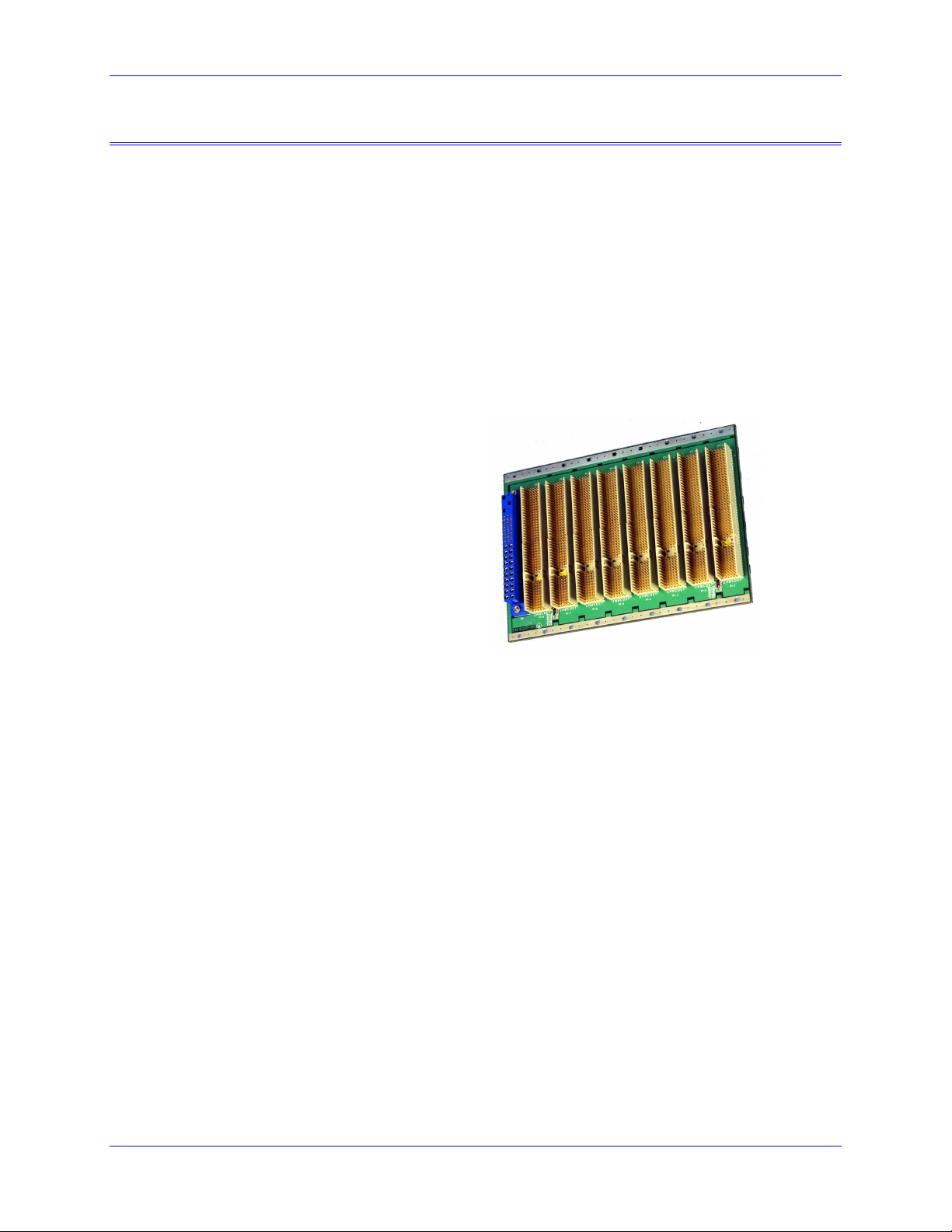
The Acc-C8 8-slot Compact UBUS Backplane board (part number 300-603617-10x) was the first of this
family to be designed. Others may be available. Contact a Delta Tau distributor for details.
The Acc-C8 8-slot backplane board:
The Compact UBUS is a high-density version of Delta Tau’s UBUS backplane bus for the original
UMAC controller. Whereas the original UBUS utilizes a VME-style 96-pin DIN connector that occupies
the full height of a 3U-format board, the Compact UBUS uses a Compact PCI-style 110-pin high-density
connector that occupies only the bottom half of a 3U-format slot. The Compact UBUS is identical in
operation, both electrically and in software, to the original UBUS; only the form factor has changed.
While the Compact UBUS uses the same connections as the Compact PCI bus, and uses the same powersupply and return pins, it is designed as a terminated bus, whereas the Compact PCI bus is un-terminated.
Every signal line on the Compact UBUS has a 330-ohm pull-up resistor at each end, and a 470-ohm pulldown resister at each end.
Introduction 1
Page 6

UMAC CPCI Accessory Cx Family
2 Introduction
Page 7

UMAC CPCI Accessory Cx Family
CONNECTIONS
In a typical configuration, the Acc-Cx Compact UBUS backplane board is installed into a standard 3Uformat Eurorack with screws and the 3U-format UMAC CPCI boards are slid into the rack so that their J1
and J2 rear connectors mate with the P1-n and P2-n connectors on the front side of the backplane board.
A rack-mounted power supply is installed into the P47-style power connector and the power source is
connected into the rear-side J1 connector. Distribution boards or cables for the field wiring are connected
to the rear-side P2-n connectors.
In a typical installation, the UMAC CPCI CPU board is simply slid into a slot of a 3U-Eurocard rack until
it inserts into the mating connectors on the backplane board already installed in the rack. In actual
operation, all signals to the board come into the CPU board through the backplane. (The front-panel RS232 connector is intended for test and debugging purposes.)
Compact UBUS Connectors
The P1-n Compact UBUS connectors along the bottom half of the front side of the backplane board
provide the means for the UMAC CPCI CPU board to communicate with axis and I/O boards through the
backplane. They also provide the 3.3V and 5V (and optionally the +/-12V) power supply lines to the 3Uformat boards. Matching pins on all P1-n (n = 1 to x on an Acc-Cx board) connectors are bussed
together.
Because of the design of the Compact UBUS, the CPU board can operate in any slot of the bus.
However, if the CPU board has the CPCI bridge board installed on it, the CPU board must be installed in
the end slot of the Compact UBUS backplane immediately adjacent to the Compact PCI bus backplane
board, so the bridge board can be installed in the adjacent CPCI end slot.
Field Wiring Connectors
The P2-n field-wiring connectors at the top of the back edge of the board provide the path for all of the
signals between each 3U-format board and the outside system. These are pass-through connectors, so that
the same signals are available on matching pins on the front and back of the same connector. Each P2-n
connector is electrically independent of all the other P2-n connectors. In a typical configuration, a
system-specific distribution system is installed behind the backplane for each P2-n connector used.
Power Supply Connector
The P{x+1} connector on the Acc-Cx (e.g. P9 for the 8-slot Acc-C8 board) connector is a P47-style
power-supply connector. It is designed so that standard 3U-format CPCI power supplies can be installed,
with voltage level V1 as +5V; V2 as +3.3V; V3 as +12V; and V4 as –12V.
Power-Input Connector
The J1 connector on the rear side of the Acc-Cx board opposite the power-supply connector provides the
means to bring in the power input to the UMAC CPCI system. These pins simply provide a pass-through
of the power-input to the rack-mounted power supply. Depending on the power supply used, an AC or
DC power input may be used.
Connections 3
Page 8

UMAC CPCI Accessory Cx Family
4 Connections
Page 9

UMAC CPCI Accessory Cx Family
BACKPLANE BOARD LAYOUT
This diagram of the UMAC CPCI Acc-C8 backplane board shows the locations of the connectors.
Detailed information about each connector follows:
PWR SUPPLY PLUG-IN,
FIRST LEFT SLOT
P2P2
Backplane Board Layout 5
Page 10

UMAC CPCI Accessory Cx Family
6 Backplane Board Layout
Page 11

UMAC CPCI Accessory Cx Family
CONNECTOR SUMMARY
P1-n:
P2-n:
P{x+1}
J1:
J2:
Compact UBUS Backplane Connectors
Thru-Backplane Field Wiring Connectors
Rack-Mounted Power Supply Connector
Line Supply Input Connector
Alternate Analog Power Connector
Connector Summary 7
Page 12

UMAC CPCI Accessory Cx Family
8 Connector Summary
Page 13

UMAC CPCI Accessory Cx Family
CONNECTOR PINOUTS
Compact UBUS Connector (P1-n) Pin-Out
For a backplane board with x data slots, the connector P1-n (n = 1 to x) is the Compact-UBUS connector
for each 3U-format board. Like signals on all P1-n connectors are bussed together.
Row Z A B C D E F
25 GND 5V 3.3V 5V GND
24 GND BD02 5V V(I/O) BD01 BD00 GND
23 GND 3.3V BD05 BD04 5V BD03 GND
22 GND BD09 BD08 3.3V BD07 BD06 GND
21 GND 3.3V BD13 BD12 BD11 BD10 GND
20 GND BD17 GND BD16 BD15 BD14 GND
19 GND 3.3V BD20 BD19 GND BD18 GND
18 GND BD23 GND 3.3V BD22 BD21 GND
17 GND 3.3V {BD26} {BD25} GND {BD24} GND
16 GND {BD30} GND {BD29} {BD28} {BD27} GND
15 GND 3.3V BWR- BRD- GND {BD31} GND
14 (KEY) (KEY) (KEY) (KEY) (KEY) (KEY) (KEY)
13 (KEY) (KEY) (KEY) (KEY) (KEY) (KEY) (KEY)
12 (KEY) (KEY) (KEY) (KEY) (KEY) (KEY) (KEY)
11 GND CS10- CS4- CS3- GND CS2- GND
10 GND CS16- GND 3.3V CS14- CS12- GND
9 GND IREQ2- IREQ1- MEMCS1- GND MEMCS0- GND
8 GND PHASE+ GND SERVO+ WAIT- IREQ3- GND
7 GND PHASE- WDO SERVO- GND GND
6 GND BA02 GND 3.3V BA01 BA00 GND
5 GND BA04 BA03 RESET- GND BX/Y GND
4 GND BA07 GND V(I/O) BA06 BA05 GND
3 GND BA11 BA10 BA09 5V BA08 GND
2 GND {BA15} 5V {BA14} BA13 BA12 GND
1 GND 5V -12V PWRGUD +12V 5V GND
Notes:
1. Row 25 is physically at the top of the connector in its normal orientation; Row 1 is at the bottom.
Looking from the front of the rack, Column Z is on the left; Column F is on the right.
2. Supply (Vxx and xxV) and ground pins are in the same locations as the Compact PCI bus.
3. Spaces marked (KEY) are for the mechanical key; these are not pins.
4. Pins marked with {} brackets are reserved for future use; the signals inside the brackets are proposed
for future expansion to a 32-bit data bus and 16-bit address bus.
Connector Pinouts 9
Page 14

UMAC CPCI Accessory Cx Family
Pass-Through (P2-n) Connectors
For a backplane board with x data slots, the connector P2-n (n = 1 to x) is the pass-through connector for
field wiring for each 3U-format board.
Row Z A B C D E F
22 GND * * * * * GND
21 GND * * * * * GND
20 GND * * * * * GND
19 GND * * * * * GND
18 GND * * * * * GND
17 GND * * * * * GND
16 GND * * * * * GND
15 GND * * * * * GND
14 GND * * * * * GND
13 GND * * * * * GND
12 GND * * * * * GND
11 GND * * * * * GND
10 GND * * * * * GND
9 GND * * * * * GND
8 GND * * * * * GND
7 GND * * * * * GND
6 GND * * * * * GND
5 GND * * * * * GND
4 GND * * * * * GND
3 GND * * * * * GND
2 GND * * * * * GND
1 GND * * * * * GND
Notes:
1. Row 25 is physically at the top of the connector in its normal orientation; Row 1 is at the bottom. Looking
from the front of the rack, Column Z is on the left; Column F is on the right.
2. The pins labeled as * simply pass through the Acc-Cx backplane board, without connecting to any other
signal on the board.
10 Connector Pinouts
Page 15

UMAC CPCI Accessory Cx Family
P{x+1}: Power Supply (P47-Style) Connector
For a backplane board with x data slots, the connector P{x+1} (e.g. P9 for the Acc-C8 8-slot board) is the
power-supply connector.
Pins 1-20: Size 16 Power-Supply Outputs to Backplane
Pin No. Description Pin No. Description
1 +5V (V1) 11 +5V/+3.3V Return (ground plane)
2 +5V (V1) 12 +5V/+3.3V Return (ground plane)
3 +5V (V1) 13 +3.3V (V2)
4 +5V (V1) 14 +3.3V (V2)
5 +5V/+3.3V Return (ground plane) 15 +3.3V (V2)
6 +5V/+3.3V Return (ground plane) 16 +3.3V (V2)
7 +5V/+3.3V Return (ground plane) 17 +3.3V (V2)
8 +5V/+3.3V Return (ground plane) 18 +3.3V (V2)
9 +5V/+3.3V Return (ground plane) 19 +12V Return (ground plane)
10 +5V/+3.3V Return (ground plane) 20 +12V (V3)
Pins 21-44: Size-20 Signal Interface Pins
21 -12V (V4) 33 +3.3V Sense (connect to center of +3.3V
power plane)
22 Signal Return 34 Sense Return
23 Reserved (no connection) 35 V1 Share (no connection on single-supply
backplane)
24 -12V Return (ground plane) 36 +12V Sense (connect to center of +12V
power plane)
25 GA0 (Supply slot address bit 0 – gro un d fo r
supply slot 0)
26 Reserved (no connection) 38 DEG#
27 EN# (ground plane) 39 INH# (leave open for no inhibit function)
28 GA1 (Supply slot address bit 1 – gro un d fo r
supply slot 0)
29 V1 ADJ (no connection – for nominal
voltage)
30 +5V Sense (connect to center of +5V power
plane)
31 GA2 (Supply slot address bit 2 – gro un d fo r
supply slot 0)
32 V2 ADJ (no connection – for nominal
voltage)
Pins 45-47: Size-16 Power-Supply Inputs from Backplane
45 Chassis GND
46 ACN / +DC In (AC Neutral/ Positive DC
input)
47 ACL / -DC In (AC Line/ Negative DC input)
37 SMB SCL (no connection)
40 SMB SCL (no connection)
41 V2 Share (no connection on single-supply
backplane)
42 FAL#
43 SMB PWR (no connection)
44 V3 Share (no connection on single-supply
backplane)
Connector Pinouts 11
Page 16

UMAC CPCI Accessory Cx Family
J1 Line Supply Input Connector
Pin # Symbol Function Description Notes
1 CHASSIS GND EARTH Connection to earth ground Important safety connection
2 ACN / DC IN+ INPUT Neutral input for AC supply;
positive input for DC supply
3 ACL / DC IN- INPUT Line input for AC supply;
negative input for DC supply
This connector on the rear side of the Acc-Cx backplane board provides the means for bringing power into the UMAC CPCI
system. These signals are simply passed through the backplane board to the power supply.
Signal level and type dependent on power
supply installed.
Signal level and type dependent on power
supply installed.
J2 Alternate Analog Power Connector
Pin # Symbol Function Description Notes
1 +12V RETURN Common Reference for +12V Supply Usually tied to –12V RETURN
2 +12V Input /
Output
3 -12V Input /
Output
4 -12V RETURN Common Reference for -12V Supply Usually tied to +12V RETURN
+12V analog supply for
backplane
-12V analog supply for
backplane
This pin can be used as input if the rack
supply does not have +12V; it can be used
as output if the rack supply provides it.
This pin can be used as input if the rack
supply does not have +12V; it can be used
as output if the rack supply provides it.
12 Connector Pinouts
 Loading...