

Page 1

^1 USER MANUAL
^2 Accessory 82M
^3 MACRO INTERFACE FOR SIGMA-II (YASKAWA)
^4 3Ax-603790-xUxx
^5 January 6, 2006
Single Source Machine Control Power // Flexibility // Ease of Use
21314 Lassen Street Chatsworth, CA 91311 // Tel. (818) 998-2095 Fax. (818) 998-7807 // www.deltatau.com
Page 2

Copyright Information
© 2006 Delta Tau Data Systems, Inc. All rights reserved.
This document is furnished for the customers of Delta Tau Data Systems, Inc. Other uses are
unauthorized without written permission of Delta Tau Data Systems, Inc. Information contained in
this manual may be updated from time-to-time due to product improvements, etc., and may not
conform in every respect to former issues.
To report errors or inconsistencies, call or email:
Delta Tau Data Systems, Inc. Technical Support
Phone: (818) 717-5656
Fax: (818) 998-7807
Email: support@deltatau.com
Website: http://www.deltatau.com
Operating Conditions
All Delta Tau Data Systems, Inc. motion controller products, accessories, and amplifiers contain
static sensitive components that can be damaged by incorrect handling. When installing or handling
Delta Tau Data Systems, Inc. products, avoid contact with highly insulated materials. Only
qualified personnel should be allowed to handle this equipment.
In the case of industrial applications, we expect our products to be protected from hazardous or
conductive materials and/or environments that could cause harm to the controller by damaging
components or causing electrical shorts. When our products are used in an industrial environment,
install them into an industrial electrical cabinet or industrial PC to protect them from excessive or
corrosive moisture, abnormal ambient temperatures, and conductive materials. If Delta Tau Data
Systems, Inc. products are directly exposed to hazardous or conductive materials and/or
environments, we cannot guarantee their operation.
Page 3

Accessory 82M
Table of Contents
INTRODUCTION .......................................................................................................................................................1
GETTING STARTED.................................................................................................................................................2
Setup of Yaskawa Drive............................................................................................................................................2
ACC-82M Yaskawa Station Setup............................................................................................................................2
ACC-82M Yaskawa Station Quick Setup .................................................................................................................3
INPUTS AND OUTPUTS ...........................................................................................................................................5
SECONDARY ENCODER.........................................................................................................................................6
Setup of ACC-82M ...................................................................................................................................................6
Setup of UMAC (and PMAC-TURBO) for Secondary Encoder ..............................................................................6
DISPLAYS ...................................................................................................................................................................7
Alphanumeric Display...............................................................................................................................................7
LINK Display............................................................................................................................................................7
WATCHDOG LED (Inside Enclosure).....................................................................................................................7
POWER GOOD LED (Inside Enclosure) .................................................................................................................7
JUMPERS ....................................................................................................................................................................8
CONNECTOR PINOUTS...........................................................................................................................................9
USB Connector – AUX Comms for Accessory card.................................................................................................9
SC-Style Fiber Interface Connector – MACRO Comms (OPT-A)...........................................................................9
RJ-45 In and Out Interface Connector – MACRO Comms (OPT-B)........................................................................9
Connector CN6 – Interface Signals for Accessory card...........................................................................................9
User Inputs Circuit Diagram..............................................................................................................................10
User Outputs Circuit Diagram ...........................................................................................................................10
High Speed TTL Outputs Circuit Diagram.........................................................................................................11
YASKAWA DUAL PORT RAM MEMORY.........................................................................................................12
Table of Contents i
Page 4

Accessory 82M
ii Table of Contents
Page 5
Accessory 82M
W
INTRODUCTION
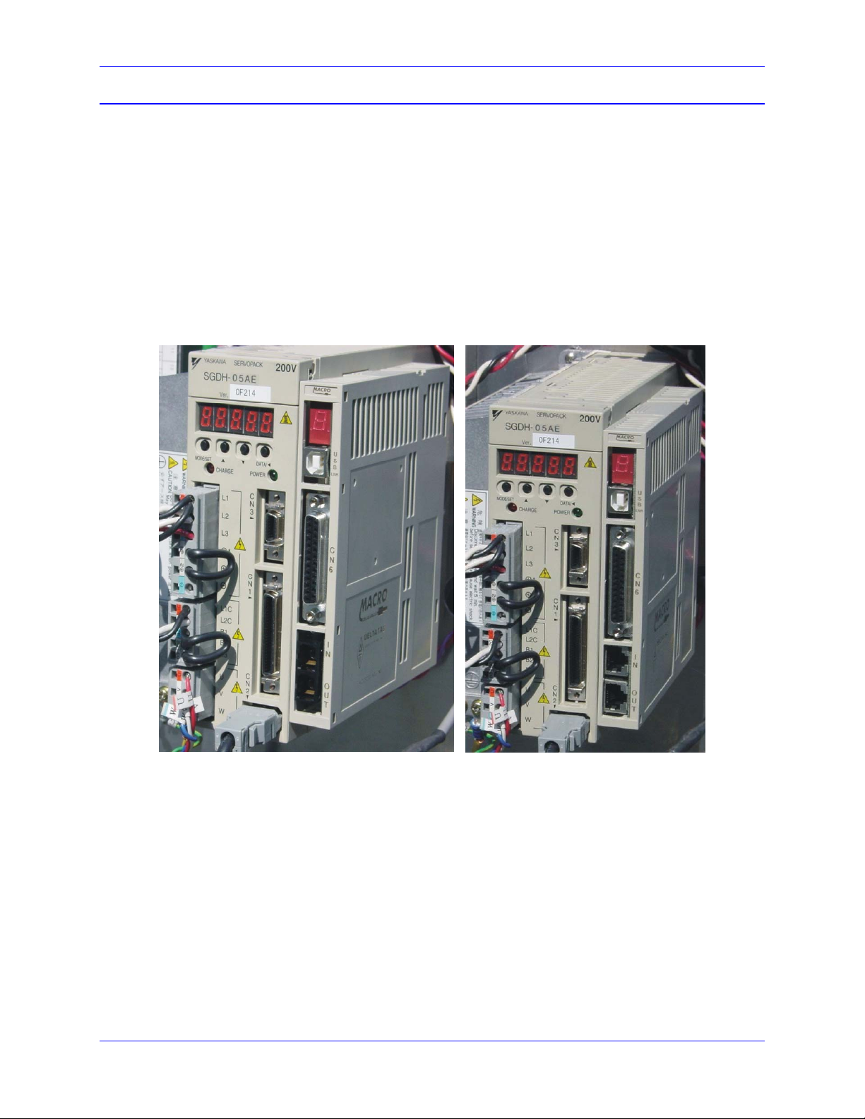
The MACRO SIGMA-II Application Module (ACC-82M) is an accessory card that connects to the
Yaskawa Sigma-II (SGDH) amplifier. The purpose of this accessory card is to provide the MACRO
fieldbus interface between Yaskawa Corp. amplifiers and Delta Tau Data Systems MACRO-based motion
controllers.
This interface accessory card provides 4 outputs that are Open-collector style. This interface card also has
4 inputs. A 25-pin DSUB connector is used for the user’s interface.
This accessory card requires the user to supply an external 12-24Vdc power supply.
It should be noted that the SGDH amplifier is identical to the SGDM amplifier except that the SGDH
amplifier has an external port connector that is used for peripheral devices. The SGDM amplifier cannot
be fitted for the ACC-82M. Contact Yaskawa for further information on exchanging amplifiers.
ACC-82M w/OPT-A
FIBER OPTIC
1
ACC-82M w/OPT-B
IRED MACRO
Page 6

Accessory 82M
GETTING STARTED
Setup of Yaskawa Drive
Perform the installation and setup of the SGDH SIGMAII drive per the recommendations of Yaskawa
Corp.
This should include the electrical installation of the motor and the drive per the instruction manual
supplied with the Yaskawa SIGMAII drive.
You may use the SIGMAWIN setup program (provided by Yaskawa Corp.) to set up the drive’s
parameters, or enter parameters using the operator interface on the front of the SIGMAII drive.
The ACC-82M operates the SIGMA-II drive in torque mode. Set Pn000 to torque mode by setting digit
#1 to the value of 2. Refer to the Appendix B in the SIGMA II User’s Manual for the list of parameters.
There are also parameters available to bypass wired functions such as SERVO ENABLE , POSITIVE
OVERTRAVEL, and NEGATIVE OVERTRAVEL. Refer to Pn50A and Pn50B for setting these
overrides.
WARNING
If the values of overrides are set to bypass the physical interface at the CN1
connector on the drive, dangerous over-travel or undesired motion may occur.
--Caution must be used when operating the drive with any overrides enabled--
ACC-82M Yaskawa Station Setup
The ACC-82M is pre-configured from the factory to operate the Yaskawa SGDH drive without very
much user interaction.
There are 4 things that must occur to get the interface to operate correctly with the drive:
1. The drive must be configured to operate using the SIGMAWIN program supplied from
Yaskawa, the operator panel on the drive, or the optional digital operator.
2. The PMAC/UMAC controller must be set to communicate with the MACRO ring.
3. Ring order must be established to allow configuration of the ACC-82M through the MACRO
ring.
4. The node number must be established in the ACC-82M and configured at parameter I996.
The phase clock at MI992 in the ACC-82M is defaulted to 5895 (10KHz) and the SERVO clock at MI998
is defaulted to 4 (2KHz). This corresponds to the value of I6800 in the UMAC of 5895. If other values of
phase clocking are used, the servo clock in the ACC-82M must be set to operate at 2KHz.
2
Page 7

Accessory 82M
ACC-82M Yaskawa Station Quick Setup
After hooking up the Ring to each of your MACRO 1x Stations, try to set up one station.
RING ORDER (At the Ring Controller)
TYPE: " MACSTA255"
If you get Macro I/O ERR08, (Make sure I6840=$4030, I6841 = $0FCxx1), I79=32, SAVE, $$$) and
then try “MACSTA255” again.
TYPE: “CLRF” ; clears any faults
TYPE: "MI996=$0F4001" (Binds to Ring Controller 0 & Node 0)
TYPE: “STN=1” ; Set MACRO Ring station number.
TYPE: “^T” ; Control T (Terminates ASCII Ring Order)
TYPE: “I6800=5895” 10 Khz Phase Clock
TYPE: “I70=1” ; Enable Ring Flag transfer
TYPE: “I71=1”
TYPE: “I78=32” ; MacroSlave command timeout
TYPE: “I110 = $100”
TYPE: “I124=$860001” ; High True AMP fault & disable limits
TYPE: “I195 = $F40000”
TYPE: “I8000 = $278420”
; The following are motor tuning parameters which may be different in your application.
TYPE: “I130= 19800” ; Servo Forward Gain
TYPE: “I131 = 2520”
TYPE: “I132 = 2520”
TYPE: “I133= 101390” ; Servo Integrator Gain
TYPE: “I134= 1
TYPE: “I116 = 10000”
TYPE: “I117 = 10”
TYPE: “I119 = 10”
TYPE: “I122 = 3277”
TYPE: “I123 = 786”
TYPE: “#1->131072X”
TYPE the following program
OPEN PROG 1 CLEAR
While (1 < 2)
F10X100
DWELL1000
3
Page 8

Accessory 82M
X0
DWELL1000
EndWhile
CLOSE
Your should be ready to Home and run the above program.
TYPE: “$*” to get the absolute position home value.
4
Page 9

Accessory 82M
INPUTS AND OUTPUTS
The ACC-82M has 4 opto-coupled inputs and 4 opto-coupled outputs. There are also 2 outputs (not optocoupled) that are connected to DO3 and DO4 that operate at high speed for secondary encoder capture
outputs.
Refer to the Delta Tau Data Systems, Inc. manual “MACRO SINGLE AXIS ACCESSORY SOFTWARE
REFERENCE MANUAL.”
Search for the MACRO1X STATION MACRO 72-bit Node I/O FORMAT located near the front of the
manual for the Flag command bits (DO1-DO4 outputs) and the flag status bits (IN_A - IN_C, HOME1).
The table below shows how the bits are organized:
INPUTS
X:$3440..X:$347F
OUTPUTS
Y:$3440..Y:$347F
23 22 21 20 19 18 17 16 15 14 13 12 11 10 9 8 7 6 5 4 3 2 1 0
IN_C IN_B IN_A HOME
DO4 DO3 DO2 DO1
By assigning M-Variables in the UMAC, these inputs and outputs become available.
MACRO node 0 is located at X/Y $3440, Node 1 is located at X/Y $3441, Node 2 is located at X/Y
$3442 etc.
NOTE
When assigning M-variables to these bits, it is important to avoid changing any of
the other bits in this word. The other bits in this word are used for real time flag
data such as amplifier fault and amplifier enable.
A reference schematic is shown for these inputs and outputs in the connector description of this manual.
5
Page 10

Accessory 82M
SECONDARY ENCODER
The secondary encoder input provides for an AquadB style encoder input that is connected through the
CN6 connector. Refer to the connector interface diagrams (later in this manual) for the pin connections to
be used.
By using the first 16-bit MACRO register in the configured slave node of the ACC-82M, the register of
the secondary encoder may be returned to the controller as a 16-bit value.
Setup of ACC-82M
Set the I109 parameter in the ACC-82M to $C091. This will insert the phase count register of the
secondary encoder register into the first 16-bit encoder register of the selected MACRO slave address.
The other registers in the accessory are set to default values to allow a quadrature encoder to operate.
I109, I910-I915, I990, I993 are parameters that are set in the accessory card which will affect the
operation of the secondary encoder. Refer to MACRO1x Software Reference for the modifications of
these I-variables.
Setup of UMAC (and PMAC-TURBO) for Secondary Encoder
The secondary encoder counter in the UMAC is returned as a 16-bit value in the MACRO register
associated with the selected amplifier.
Position data is obtained in the UMAC by configuring the encoder conversion table to fetch the value
from the returned MACRO data.
Please refer to the PMAC2-TURBO software reference to obtain the addressing for the data. The
information pertaining to the encoder conversion table setup is found at the “CONVERSION TABLE IVARIABLES” definition using Parallel Feedback Entries. The address map for the returned data from the
MACRO ring is located in the “TURBO PMAC MEMORY AND I/O MAP” chapter of the Software
Reference. Search for Turbo “PMAC2 MACRO Node Registers” and use the first 16 bit feedback register
address for the particular node that is used.
The example below shows the encoder conversion table entry for a secondary encoder that is used for axis
#1 position.
EXAMPLE:
st
I8000=$678421 ;Parallel data read at location $78421 (node0 1
I8001=$010008 ;Read 16 bits wide starting at bit 8.
I103=$3502 ;Point inputs to second encoder entry line.
I104=$3502
16-bit register)
6
Page 11

Accessory 82M
DISPLAYS
All displays appear at the front panel of this accessory card.
Alphanumeric Display
The following codes may be displayed:
0: Ring Active with no errors
1: Amp enabled
A: AMP Fault (latched on a fault, cleared by MSCLRF & AMP ENA)
B: Ring-break fault (Amp is disabled)
C: Configuration change fault
D: Ring data-error fault (Amp is disabled)
Flashing Display:
This indicates that the ACC-82M is in the ASCII mode.
Note
If the display is blank, this indicates that ring communications are not active,
which means that this value cannot be reported back to the controller.
LINK Display
This bi-color LED turns green when the MACRO signal is present. This LED is red when the MACRO
signal is not present.
WATCHDOG LED (Inside Enclosure)
This red LED illuminates when the watchdog circuit triggers. This usually means that there is a failure of
the processor in the ACC-82M or that the bootstrap jumper is not correctly installed.
This is D5 located on the PCB inside the enclosure.
POWER GOOD LED (Inside Enclosure)
This green LED illuminates to indicate that the power supply is operating correctly in the ACC-82M.
This is D6 located on the PCB inside the enclosure.
7
Page 12

Accessory 82M
JUMPERS
Jumpers are configured as follows:
Factory Setting
E1 Watchdog bypass – No Jumper Installed
E3 Normal/Bootstrap Operation
1 – 2 Bootstrap Load
2 – 3 Normal Operation
E4 Servo Clock inversion
1 – 2 Non-Inverted
2 – 3 Inverted
E5 Not used
JP1-JP4 Not used
2 – 3 Normal Operation
1 – 2 Non- inverted clock.
8
Page 13

Accessory 82M
CONNECTOR PINOUTS
All interface signals appear at the front panel of this accessory card.
USB Connector – AUX Comms for Accessory card
This is a standard USB interface connector. This is used for direct communications with the accessory
card processor.
SC-Style Fiber Interface Connector – MACRO Comms (OPT-A)
This is the fiber optic MACRO interface connector.
RJ-45 In and Out Interface Connector – MACRO Comms (OPT-B)
These are the wired MACRO interface connector.
Connector CN6 – Interface Signals for Accessory card
This is a DB25S pin DSUB connector. The user needs a DB25P style connector.
Pin# Signal
Type Description
Name
1 +5Vdc OUTPUT Power supply output for encoder.
2 GND Digital ground
3 CHA+ INPUT Secondary encoder input
4 CHB+ INPUT Secondary encoder input
5 CHC+ INPUT Secondary encoder input
6 IN_C INPUT Flag_D
7 IN_A INPUT Flag_B
8 FL_RT INPUT RET for flags
9
10 DO1 Open
Collector
11 DO3 Open
Collector
12 OUT_COM COM return for DOx lines
13 GND POWER USER SUPPLIED 12-24Vdc Power Supply
14 EQU1/OUT3 TTL High Speed TTL output
15 EQU2/OUT4 TTL High Speed TTL output
16 CHA- INPUT Secondary encoder input
17 CHB- INPUT Secondary encoder input
18 CHC- INPUT Secondary encoder input
19 IN_B INPUT Flag_C
20 HOME INPUT Flag_A
21
22
23 DO2 Open
Collector
24 DO4 Open
Collector
25 +24Vdc POWER USER SUPPLIED 12-24Vdc Power Supply
User-defined output
User-defined output
User-defined output
User-defined output
9
Page 14

Accessory 82M
User Inputs Circuit Diagram
U6
A1
C1E1
A1
C1E1
A1
C1E1
A1
C1E1
1
23
U11
1
23
U12
1
23
U13
1
23
C43
.1UF
C42
.1UF
C44
.1UF
GND
4
C1
4
C1
4
C1
4
C1
PS2705-1
RP2
1 2
3 4
5 6
7 8
4.7KSIP8I
RP3
7 8
5 6
3 4
1 2
4.7KSIP8I
RP4
1 2
3 4
5 6
7 8
XXSIP8I
RP5
1 2
3 4
5 6
7 8
1KSIP8I
(IN SOCKET)
IN_C
IN_B
IN_A
HOME1
FL_RT1
NOTE: INSTALL ONLY
FOR +5V LIMIT
INPUT
(1K SIP, 8 PIN, 4 RES)
User Outputs Circuit Diagram
1
A1
2 3
C1 E1
1
A1
2 3
C1 E1
1
A1
2 3
C1 E1
1
A1
2 3
C1 E1
PS2701-1
GND
C1
C1
C1
C1
U34
4
U35
4
U36
4
U37
4
R90 3.3K
R88 3.3K
1
R83 3.3K
R85 3.3K
1
23
1
23
Q8
MMBT3906LT1
OPEN COLLECTOR OUTPUTS
Q7
MMBT3906LT1
1
23
Q6
MMBT3906LT1
23
Q5
MMBT3906LT1
DOUT1
DOUT2
DOUT3
DOUT4
OUT_COM
10
Page 15

Accessory 82M
High Speed TTL Outputs Circuit Diagram
U16A
DO3
DO4
1
2
DS75452M
(SO8)
U16B
7
6
3
5
EQU1/OUT_3
+5V
GND
EQU2/OUT_4
C56
.1UF
DS75452M
(SO8)
This circuit requires
external pullup resistors
11
Page 16

Accessory 82M
YASKAWA DUAL PORT RAM MEMORY
Memory Description Macro Station CPU to AMP
Y:$4000 Not used
X:$4000 Watch Dog Counter
Y:$4001 Command Word (Contains AMP ENA bit 1, Reset AMP Faults bit 4
y:$4002 Clear Following Error = bit 7
X:$4002 Latch Request Flg LT {Home ENA) = bit 7
X:$400E $0x0B = Ring Break
$0x0D =Ring Data Error
$0x08 = (Generic Station Fault)
Memory Description AMP to Macro Station CPU
X:$4040 Watch Dog Counter
x:$4041 Status Word (Contains AMP Fault bit 1)
x:$4042 Status Word AMP FAULT bits 4-6, Latch Complete Flag (Home
Complete) bit 7
X/Y:$4046 Position Feedback
X/Y:$4047 Position Feedback
X/Y:$4048 Latched Position Feedback
X/Y:$4049 Latched Position Feedback
12
 Loading...