

Delta Tau 5xx-603869-xUxx User Manual
^1 HARDWARE REFERENCE MANUAL
125
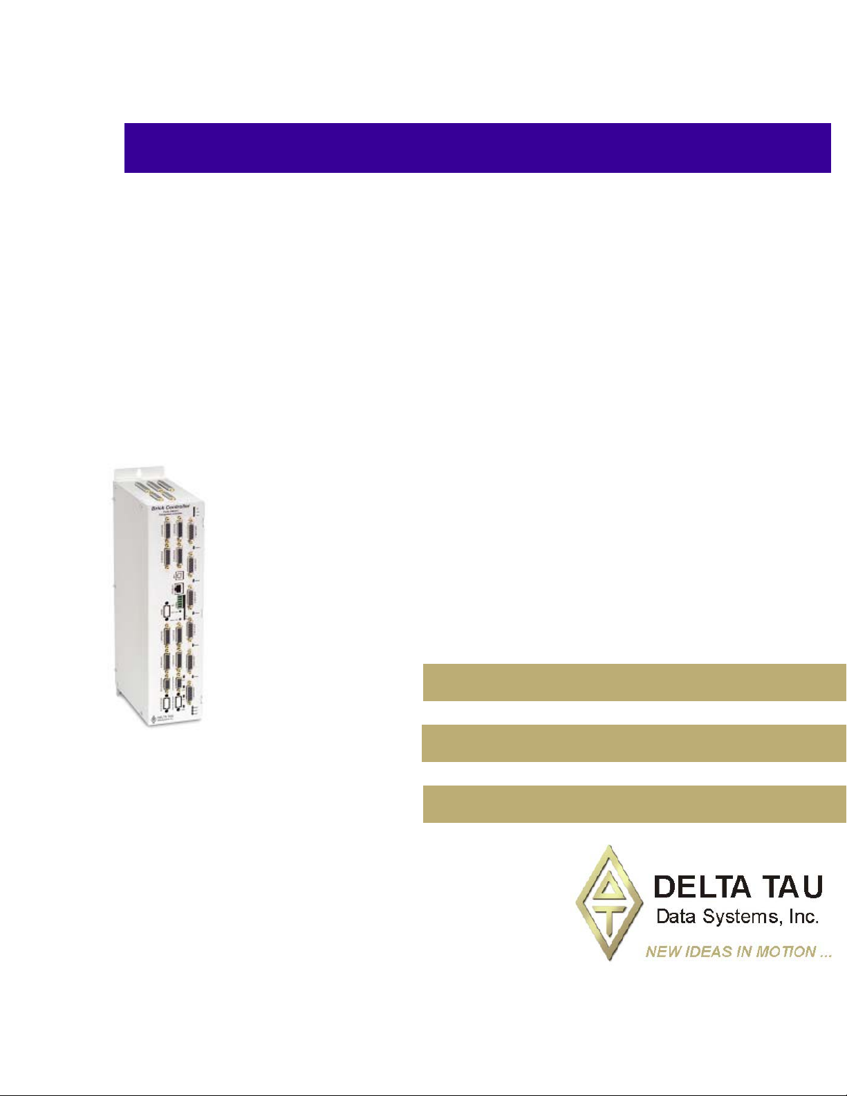
^2 Brick Motion Controller
^3 Programmable Servo Amplifier
Single Source Machine Control Power // Flexibility // Ease of Use
21314 Lassen Street Chatsworth, CA 91311 // Tel. (818) 998-2095 Fax. (818) 998-7807 // www.deltatau.com
^4 5xx-603869-xUxx
^5 May 2, 2007

Copyright Information
© 2007 Delta Tau Data Systems, Inc. All rights reserved.
This document is furnished for the customers of Delta Tau Data Systems, Inc. Other uses are
unauthorized without written permission of Delta Tau Data Systems, Inc. Information contained in this
manual may be updated from time-to-time due to product improvements, etc., and may not conform in
every respect to former issues.
To report errors or inconsistencies, call or email:
Delta Tau Data Systems, Inc. Technical Support
Phone: (818) 717-5656
Fax: (818) 998-7807
Email: support@deltatau.com
Website: http://www.deltatau.com
Operating Conditions
All Delta Tau Data Systems, Inc. motion controller products, accessories, and amplifiers contain static
sensitive components that can be damaged by incorrect handling. When installing or handling Delta Tau
Data Systems, Inc. products, avoid contact with highly insulated materials. Only qualified personnel
should be allowed to handle this equipment.
In the case of industrial applications, we expect our products to be protected from hazardous or
conductive materials and/or environments that could cause harm to the controller by damaging
components or causing electrical shorts. When our products are used in an industrial environment, install
them into an industrial electrical cabinet or industrial PC to protect them from excessive or corrosive
moisture, abnormal ambient temperatures, and conductive materials. If Delta Tau Data Systems, Inc.
products are directly exposed to hazardous or conductive materials and/or environments, we cannot
guarantee their operation.
Safety Instructions
Qualified personnel must transport, assemble, install, and maintain this equipment. Properly qualified
personnel are persons who are familiar with the transport, assembly, installation, and operation of
equipment. The qualified personnel must know and observe the following standards and regulations:
IEC 364 resp. CENELEC HD 384 or DIN VDE 0100
IEC report 664 or DIN VDE 0110
National regulations for safety and accident prevention or VBG 4
Incorrect handling of products can result in injury and damage to persons and machinery. Strictly adhere
to the installation instructions. Electrical safety is provided through a low-resistance earth connection. It
is vital to ensure that all system components are connected to earth ground.
This product contains components that are sensitive to static electricity and can be damaged by incorrect
handling. Avoid contact with high insulating materials (artificial fabrics, plastic film, etc.). Place the
product on a conductive surface. Discharge any possible static electricity build-up by touching an
unpainted, metal, grounded surface before touching the equipment.
Keep all covers and cabinet doors shut during operation. Be aware that during operation, the product has
electrically charged components and hot surfaces. Control and power cables can carry a high voltage,
even when the motor is not rotating. Never disconnect or connect the product while the power source is
energized to avoid electric arcing.

After removing the power source from the equipment, wait at least 10 minutes before touching or
disconnecting sections of the equipment that normally carry electrical charges (e.g., capacitors, contacts,
screw connections). To be safe, measure the electrical contact points with a meter before touching the
equipment.
The following text formats are used in this manual to indicate a potential for personal injury or equipment
damage. Read the safety notices in this manual before attempting installation, operation, or maintenance
to avoid serious bodily injury, damage to the equipment, or operational difficulty.
WARNING:
A Warning identifies hazards that could result in personal injury or death. It
precedes the discussion of interest.
Caution:
A Caution identifies hazards that could result in equipment damage. It precedes
the discussion of interest
Note:
A Note identifies information critical to the user’s understanding or use of the
equipment. It follows the discussion of interest.


REVISION HISTORY
REV. DESCRIPTION DATE CHG APPVD
1 MANUAL CREATION 05/02/07 CP S. MILICI


Brick Motion Controller Hardware Reference Manual
Table of Contents
125 ................................................................................................................................................................................. I
Copyright Information.............................................................................................................................................. ii
Operating Conditions ............................................................................................................................................... ii
Safety Instructions.................................................................................................................................................... ii
INTRODUCTION .......................................................................................................................................................1
Brick Motion Controller Features .............................................................................................................................1
SPECIFICATIONS .....................................................................................................................................................3
Part Number ..............................................................................................................................................................3
Brick Motion Controller Options..........................................................................................................................3
RECEIVING AND UNPACKING.............................................................................................................................5
Use of Equipment......................................................................................................................................................5
SYSTEM WIRING......................................................................................................................................................7
Noise Problems.....................................................................................................................................................7
Wiring Earth-Ground ................................................................................................................................................7
Earth Grounding Paths.........................................................................................................................................7
Connectors.................................................................................................................................................................8
X1-X8: Encoder Input (1 to 8)..............................................................................................................................8
X9-10: Analog I/O Ch5 (X9) and Ch6 (X10), (Optional) ....................................................................................9
X11-12: Analog I/O Ch7 (X11) and Ch8 (X12), (Optional) ................................................................................9
X13: USB 2.0 Connector ...................................................................................................................................10
X14: RJ45, Ethernet Connector.........................................................................................................................10
X15: Watchdog ...................................................................................................................................................10
TB1: Power Connector .......................................................................................................................................11
S1: Re-Initialization on Reset Control...............................................................................................................11
S2: Firmware Reload Enable ............................................................................................................................11
J4 Limit Inputs (1-4 Axis) ...................................................................................................................................12
J5 Limit Inputs (5-8 Axis) ...................................................................................................................................13
AMP1-AMP8: Amplifier connections (1 to 8).....................................................................................................15
J6: General Purpose I/O....................................................................................................................................17
Suggested M-Variable Addressing for the General Purpose I/O (J6) ................................................................18
J7: Extra General Purpose I/O (Optional).........................................................................................................19
Suggested M-Variable Addressing for the optional General Purpose I/O (J7) ..................................................20
J8: Extra General Purpose I/O (Optional)........................................................................................................21
Suggested M-Variable Addressing for the General Purpose I/O (J8) ................................................................22
Setting up Quadrature Encoders..............................................................................................................................24
Signal Format .....................................................................................................................................................24
Hardware Setup..................................................................................................................................................24
Encoder Loss Setup.............................................................................................................................................25
Setting up the Analog Inputs (optional)..............................................................................................................26
Filtered DAC Outputs Configuration (optional) ................................................................................................26
Setting up for Pulse and Direction Output...............................................................................................................29
Software Setup ....................................................................................................................................................29
Actions on Watchdog Timer Trip........................................................................................................................33
Diagnosing Cause of Watchdog Timer Trip .......................................................................................................33
APPENDIX A.............................................................................................................................................................35
DB- Connector Spacing Specifications...................................................................................................................35
X1-8: DB-15 Connectors for encoder feedback..................................................................................................35
X9-12: DB-9 Connectors for Analog I/O............................................................................................................35
Screw Lock Size for all DB-connectors ..............................................................................................................35
Type of Cable for Encoder Wiring..........................................................................................................................36
Table of Contents i

Brick Motion Controller Hardware Reference Manual
APPENDIX B.............................................................................................................................................................38
Schematics...............................................................................................................................................................38
X15: Watchdog ..................................................................................................................................................38
J6 and J7: General Purpose I/O........................................................................................................................38
J4: Limit Inputs for Axis 1-4..............................................................................................................................40
J5: Limit Inputs for Axis 5-8..............................................................................................................................41
Dimensional Layout and Connector location.....................................................................................................42
ii Table of Contents
Brick Motion Controller Hardware Reference Manual
INTRODUCTION
The Brick Motion Controller is a fully scaleable automation controller utilizing
the intelligence and capability of its embedded Turbo PMAC2. With the ability
to store programs locally and built-in PLC execution, it is programmable for
virtually any kind of automation application. This allows for complete machine
motion and logic control.
This product has 4 or 8 (optional) axes of analog +/-10V filtered-PWM (12-bit
resolution) or pulse and direction outputs as standard. Options are available for
dual true-DAC analog outputs at 18-bit resolution or Direct-PWM with current
loop. Feedback with quadrature incremental encoders is standard. Options for
sinusoidal, resolver or serial encoders are available.
The Brick Motion Controller provides a standard I/O capability of 16 inputs
and 8 outputs at 12-24volts fully protected and isolated with separate commons
for each bank of 8 inputs. Outputs are rated for 1 ampere each and are thermalfuse protected. Outputs can be current sinking or sourcing depending on use of
common emitter or common collector connections. Additional I/O is an option
(up to 64 inputs and 32 outputs). Also an option for up to four 16 bit analog
inputs is available.
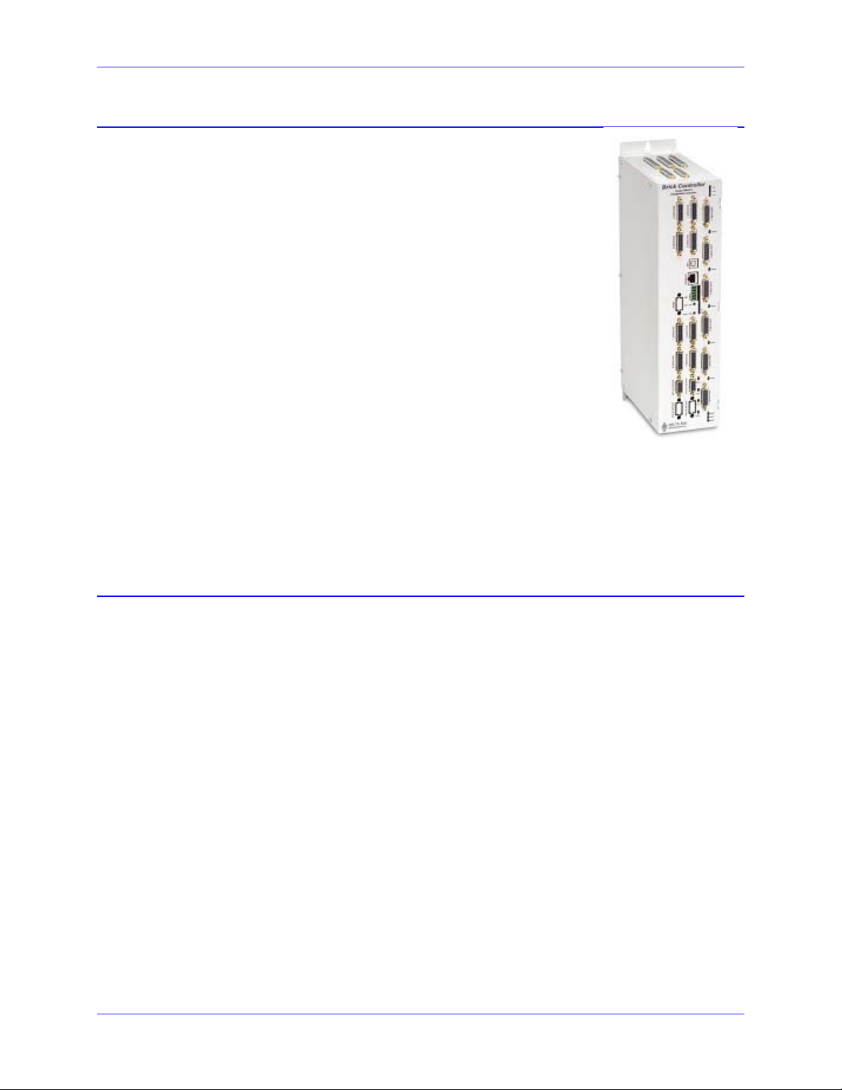
Brick Motion
Controller
The Brick Motion Controller’s functionality doesn’t stop there, but also includes features such as
extensible I/O via ModBus TCP master, or ModBus TCP slave for third party HMI hardware. Our PCbased HMI package connected through USB 2.0 or Ethernet makes the Brick Motion Controller a
powerful single-source solution.
Brick Motion Controller Features
The Brick Motion Controller is capable of controlling up to eight axes with direct-PWM commands.
• Motorola DSP 56k digital signal processor
• Turbo PMAC2 CPU (for kinematics, open servo, NC applications)
• Fully Configurable via USB2.0 and/or Ethernet TCP/IP (100 Base-T)
• Operation from a PC
• Stand-alone operation
• Linear and circular interpolation
• 256 motion programs capacity
• 64 asynchronous PLC program capability
• Rotating buffer for large programs
• 36-bit position range (± 64 billion counts)
• Adjustable S-curve acceleration and deceleration
• Cubic trajectory calculations, splines
• Set and change parameters in real time
• Torque, Velocity and Position control standard
• Small footprint saves space
• Full rated temperature cooling standard (no need for additional fans)
• 16 inputs (expandable to 32 with option) fully-protected and isolated with separate commons for
two banks of eight
• Eight thermal-fuse protected outputs (expandable to 16 with option) rated for 0.5A @ 24VDC
each (Flexible outputs allow for sinking or sourcing of current depending on whether the common
emitter or common collector is used.)
Introduction 1

Brick Motion Controller Hardware Reference Manual
• Primary encoder for each axis with TTL differential/single-ended inputs with A, B quadrature
channels and C index channel, 10 MHz cycle rate, and digital Hall-effect inputs
• Five flags per axis using DB-25: HOME, PLIM, MLIM and USER inputs; EQU compare
• Optional analog inputs and outputs, ± 5VDC
• Optional two PWM outputs.
• Optional Dual Port RAM (Required for NC)
• Optional Modbus Protocol
• Optional Sinusoidal encoder feedback
• Optional Resolver feedback
• Optional EnDat, Hiperface interfaces.
2 Introduction

Brick Motion Controller Hardware Reference Manual
SPECIFICATIONS
Part Number
Brick Controller
Model Number Definition
CPU Options - Turbo P MAC 2 Processor
C0 : 80Mhz, 8Kx24 Internal, 256Kx24SRAM, 1MB Flash (Default)
F3: 240Mhz, 192Kx24 Internal, 1Mx24SRAM, 4MB Flash
Number of Axes
4: Four Axes (Default)
8: Eight Axes
BC4 - C0 - F00 - 000 – (0000)
Axis 1-4 Output Options
F: Filtered-PWM analog output on Channels 1-4, 12-bit resolution (default)
D: Dual true-DAC analog outputs on Channels 1-4, 18-bit resolution
Dig ital I/O Optio n
0: Digital I/O 16 inputs and 8 outputs, 0.5A, 24VDC (default)
1: Expanded digital I/O additional 16 inputs and 8 outputs, 0.5A, 24VDC
2: Expanded digital I/O additional 32 inputs and 16 outputs, 0.5A, 24VDC
Analog I/O Options
0: No Options (default)
3: Two 16-bit analog inputs
4: Four 16-bit analog inputs
Axis 5 -8 Feedback Options , apply onl y to BC4 controller
Note: For Other Feedback Options See “Special Feedback Options”
00: No added encoders or flags, 12-24V flags on Channels 1-4 (default)
02: Four added encoders (Channels 5-8), four added flag sets, 12-24V flags all channels
05: No added encoders or flags, 5V flags on Channels 1-4
07: Four added encoders (Channels 5-8), four added flag sets, 5V flags all channels
Axis 5 -8 Options , apply on ly to BC 8 controller
Note : Letter must be s ame as previous letter
F2: Filtered-PWM analog output on Channels 5-8, 12-bit resolution, 12-24V flags all channels
D2: Dual true-DAC analog outputs on Channels 5-8, 18-bit resolution, 12-24V flags all channels
F7: Filtered-PWM analog output on Channels 5-8, 12-bit resolution, 5V flags all channels
D7: Dual true-DAC analog outputs on Channels 5-8, 18-bit resolution, 5V flags all channels
Communication Options
Note: To use PMAC-NC software, DPRAM is required
0: No Options, Default
D: DPRAM option, size 32K x 16-bit wide (required for NC software)
M: ModBus Ethernet Communication Protocol (So ftware) opti on
S: DPRAM and Modbus Options Combined
R: RS232 port on 9-pin D-sub Connector
E: DPRAM & RS232 Options Combined
N: RS232 & ModBus Options Combined
T: Modbus, DPRAM & RS232 Combined
MAC RO and Sp ecial Feedback Opti ons (See Not e)
Number and Type of Special Feedback Channels
BC X - XX - XXX - XXX -XXXX
00: No Special Feedback Channels
4A: 4 Sinusoidal Encoder Feedback Channels
4B: 4 Resolver Feedback Channels
4C: 4 Serial Encoder Feedback Channels
4D: 4 Sinusoidal Encoder and Serial Encoder Feedback Channels
8A: 8 Sinusoidal Encoder Feedback Channels
8B: 8 Resolver Feedback Channels
8C: 8 Serial Encoder Feedback Channels
8D: 8 Sinusoidal Encoder and Serial Encoder Feedback Channels
Ser ial Encoder Protocols
BC X - XX - XXX - XXX -XXXX
0: No Serial Encoder Protocol (for previous digit = 0, A, or B)
1: SSI
2: Yaska wa Sigma II
3: EnDat
4: HiperFace
5: Tamagawa
MACRO Ring Interface
BC X - XX - XXX - XXX -XXX
0: No MACR O Interface
1: RJ45 MACRO Interface
2: Fi ber Opti c MACRO In terface
Note: If this portion of the model number is
present at all, an add-in board with RS-232
comms port, 2 channel "handwheel" port and 8
relay outputs for the amplifier-enable signals will
be provided, regardless of the values in this
portion of the model number. Addit ional circuits
X
are provided as specified by the codes here.
Brick Motion Controller Options
CPU Options
• Option C0 – 80MHz Turbo CPU with 8Kx24 internal memory, 1Mx24 256Kx24 SRAM, 1Mx8 flash
memory
• Option F3 – 240MHz Turbo CPU with 192Kx24 internal memory, 1Mx24 SRAM, 4Mx8 flash memory
Axis 1-4 Output Options
• Filtered-PWM analog output on Channels 1-4, 12-bit resolution (default)
• Dual true-DAC analog outputs on Channels 1-4, 18-bit resolution
Secondary Encoder Options
• Four secondary encoder inputs, and flags 12-24V.
• Four secondary encoder inputs, and flags 5V.
Digital I/O Option
• Digital I/O 16 inputs and 8 outputs, 0.5A, 24VDC (default)
• Expanded digital I/O additional 16 inputs and 8 outputs, 0.5A, 24VDC
• Expanded digital I/O additional 32 inputs and 16 outputs, 0.5A, 24VDC
Specifications 3

Brick Motion Controller Hardware Reference Manual
Analog I/O Options
• Two 16-bit analog inputs
• Four 16-bit analog inputs
Communication Options
• DPRAM option, size 32K x 16-bit wide (required for use with NC software)
• ModBus Ethernet Communication Protocol (Software) option
• DPRAM and Modbus options combined
• RS232 port on 9-pin D-sub connector
• DPRAM & RS232 options combined
• Modbus & DPRAM options combined
• Modbus, DPRAM & RS232 options combined
MACRO and Special Feedback Options
Number and Type of Special Feedback Channels
• No Special Feedback Channels
• 4 Sinusoidal Encoder Feedback Channels
• 4 Resolver Feedback Channels
• 4 Serial Encoder Feedback Channels
• 4 Sinusoidal Encoder and Serial Encoder Feedback Channels
• 8 Sinusoidal Encoder Feedback Channels
• 8 Resolver Feedback Channels
• 8 Serial Encoder Feedback Channels
• 8 Sinusoidal Encoder and Serial Encoder Feedback Channels
Serial Encoder Protocols
• No Serial Encoder Protocol (for previous digit = 0, A, or B)
• SSI Serial Absolute Encoder Interface
• Yaskawa Sigma II Serial Absolute Encoder Interface
• EnDat Serial Absolute Encoder Interface
• HiperFace Serial Absolute Encoder Interface
• Tamagawa Serial Absolute Encoder Interface
MACRO Ring Interface
• RJ45 MACRO Interface
• Fiber Optic MACRO Interface
4 Specifications

Brick Motion Controller Hardware Reference Manual
RECEIVING AND UNPACKING
Delta Tau products are thoroughly tested at the factory and carefully packaged for shipment. When the
Brick Motion Controller is received, there are several steps that should be performed immediately:
1. Observe the condition of the shipping container and report any damage immediately to the
commercial carrier that delivered the drive.
2. Remove the control from the shipping container and remove all packing materials. Check all
shipping material for connector kits, documentation, diskettes, CD ROM, or other small pieces of
equipment. Be aware that some connector kits and other equipment pieces may be quite small and
can be accidentally discarded if care is not used when unpacking the equipment. The container and
packing materials may be retained for future shipment.
3. Verify that the part number of the unit received is the same as the part number listed on the purchase
order.
4. Inspect the unit for external physical damage that may have been sustained during shipment and
report any damage immediately to the commercial carrier that delivered the drive.
5. Electronic components in this product are design-hardened to reduce static sensitivity. However, use
proper procedures when handling the equipment.
6. If the Brick Motion Controller is to be stored for several weeks before use, be sure that it is stored in a
location that conforms to published storage humidity and temperature specifications stated in this
manual.
Use of Equipment
The Brick Motion Controller is a Turbo PMAC2 controller. So parallel with this manual the user needs to
use the Turbo Software Reference Manual and the Turbo User Manual. Always download the latest
manual revision from the Delta Tau website: www.deltatau.com
Note:
If Ethernet communications are used, Delta Tau Systems strongly recommends the
use of RJ45 CAT5e or better shielded cable.
Newer network cards have the Auto-MDIX feature that eliminates the need for
crossover cabling by performing an internal crossover when a straight cable is
detected during the auto-negotiation process.
For older network cards, one end of the link must perform media dependent
interface (MDI) crossover (MDIX), so that the transmitter on one end of the data
link is connected to the receiver on the other end of the data link (a crossover/patch
cable is typically used). If an RJ45 hub is used, then a regular straight cable should
be implemented.
Maximum length for Ethernet cable should not exceed 100m (330ft).
Specifications 5

Brick Motion Controller Hardware Reference Manual
6 Specifications

Brick Motion Controller Hardware Reference Manual
SYSTEM WIRING
WARNING:
Installation of electrical control equipment is subject to many regulations including
national, state, local, and industry guidelines and rules. General recommendations
can be stated but it is important that the installation be carried out in accordance
with all regulations pertaining to the installation.
Noise Problems
When problems do occur often it points to electrical noise as the source of the problem. When this
occurs, turn to controlling high-frequency current paths. If the grounding instructions do not work, insert
chokes in the motor phases. These chokes can be as simple as several wraps of the individual motor leads
through a ferrite ring core (such as Micrometals T400-26D). This adds high-frequency impedance to the
outgoing motor cable thereby making it harder for high-frequency noise to leave the control cabinet area.
Care should be taken to be certain that the core’s temperature is in a reasonable range after installing such
devices.
Wiring Earth-Ground
Panel wiring requires that a central earth-ground location be installed at one part of the panel. This
electrical ground connection allows for each device within the enclosure to have a separate wire brought
back to the central wire location. Usually, the ground connection is a copper plate directly bonded to the
back panel or a copper strip with multiple screw locations. The Brick Motion Controller is brought to the
earth-ground via the fourth pin on the J1 connector, located at the bottom of the unit through a heavy
gauge, multi-strand conductor to the central earth-ground location.
Earth Grounding Paths
High-frequency noises from the PWM controlled power stage will find a path back to the drive. It is best
that the path for the high-frequency noises be controlled by careful installation practices. The major
failure in problematic installations is the failure to recognize that wire conductors have impedances at
high frequencies. What reads 0 Ohms on a DVM may be hundreds of Ohms at 30MHz. Consider the
following during installation planning:
1. Star point all ground connections. Each device wired to earth ground should have its own conductor
brought directly back to the central earth ground plate.
2. Use unpainted back panels. This allows a wide area of contact for all metallic surfaces reducing high
frequency impedances.
3. Conductors made up of many strands of fine conducts outperform solid or conductors with few
strands at high frequencies.
4. Motor cable shields should be bounded to the back panel using 360-degree clamps at the point they
enter or exit the panel.
5. Motor shields are best grounded at both ends of the cable. Again, connectors using 360-degree shield
clamps are superior to connector designs transporting the shield through a single pin. Always use
metal shells.
6. Running motor armature cables with any other cable in a tray or conduit should be avoided. These
cables can radiate high frequency noise and couple into other circuits.
System Wiring 7
 Loading...