

Page 1
DO 9704
INSTRUCTIONS MANUAL
Page 2
1
20
2
3
4
6
5
7
8
9
10
11
12
13
14
15
16
17
18
19
22
21
23
24
25
26
27
28
29
30
31
32
33
34
35
36
DO 9704
Page 3

67
DO 9704
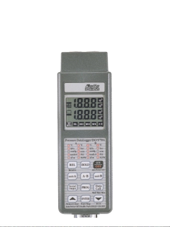
PRESSURE AND TEMPERATURE - DATA-LOGGER
ENGLISH
Page 4

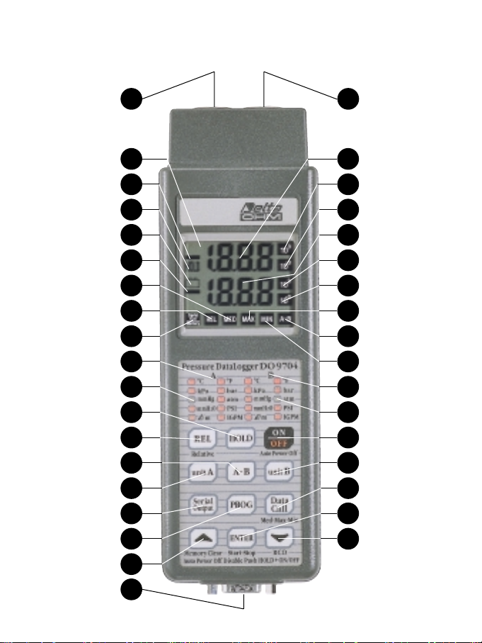
1 Input A, DIN 8-pole connector for pressure, flow rate or temperature.
2 Display.
3 Negative symbol input A.
4 HOLD symbol.
5Hsymbol: flashes during RECORD function, permanently lit if the battery is running low.
6 Negative symbol input B.
7 The display shows the Mean values.
8 REL symbol, indicates that the instrument is making a relative measurement.
9 Memory/Serial Out. Fixed symbol: the instrument is storing. Flashing symbol: serial output is
enabled.
10 Measurement units that may be selected at input A.
11 Measurement unit selected at input A.
12 HOLD key for blocking the reading.
13 REL key, the value shown is related to the indication at the moment in which the REL key was
pressed.
14 A-B key. The instrument displays the difference between the inputs.
15 Unit A: Key for selecting the measurement unit for input A.
16 Serial Output: enables unloading of data at the RS 232C serial output.
17 Prog: this key is pressed to enter the routine for programming the various functions of the
instrument.
18skey. When enabled, this key increases the displayed parameter.
19 Output for RS 232C (SUB D male 9-pole).
20 Input B, DIN 8-pole connector for pressure, flow rate or temperature.
21 Input A indication.
22 Multiplication channel for channel A 10
3
.
23 Multiplication channel for channel A 10
–3
.
24 Input B indication.
25 Multiplication channel for channel B 10
3
.
26 Multiplication channel for channel B 10
–3
.
27 The display shows the Maximum values.
28 The display shows the difference in value between inputs A or B.
29 The display shows the Minimum values.
30 Measurement units that may be selected at input B.
31 Measurement unit selected at input B.
32 Key for switching the instrument on and off.
33 Unit B. Key for selecting the measurement unit for input B.
34 When pressed in sequence, the display indicates the Maximum peak value, the Minimum value
and the Mean value.
35 The key has various functions: it starts and stops storage, confirms the set parameters.
36tkey. When enabled, this key decreases the displayed values, starts and stops the RECORD
function.
ENGLISH
68
Page 5

INTRODUCTION
The DELTA OHM DO 9704 pressure gauge and data logger has been designed for detecting pres-
sure, flow rate and temperature, physical values which are very important in industrial and chemical
processes.
The instrument has two inputs, A and B, and automatically recognises the probes connected,
whether they be pressure or temperature probes or turbines for measuring flow rate, and displays
the difference between the two inputs.
As the probes are interchangeable, it is possible to choose the most suitable combination for all
applications without having to recalibrate the instrument. The operating principle of the pressure
sensor is based on the bending of a membrane in a watertight chamber in contact with the flow of
which you want to measure the pressure. The flow may be liquid or gas. The flow rate measurement is based on the number of impulses or the frequency of a small fan.
The DO 9704 is able to measure differential or relative pressure for air or non corrosive gases,
absolute and relative pressure for measurements in contact with liquids or gases, in 6 different
measurement units; temperature (in °C or °F); flow rate in the range for 2 to 2000 litres/minute with
a turbine in the measurement units LPM (litres per minute) or IGPM (Imperial Gallons per Minute).
The instrument’s Data Logger function enables it to store up to 30,000 readings. The sampling
period is variable from 1 second to 12 hours.
The data acquired may later be transferred to a Personal Computer or a printer by means of the
opto-insulated serial line RS 232C. For each value stored the date and time of acquisition are indicated; each acquisition block is ended with a report which provides the maximum (peak), minimum
and mean values
With the Serial Output function it is possible to obtain the instantaneous values measured by the
instrument at the output of the serial line RS 232C, in order to send them to a printer or a computer.
Other functions such as HOLD (which blocks the display), REL (for taking relative measurements)
and RECORD (for storing the maximum, minimum and mean values) further enrich the instrument’s
performance.
Thanks to its versatility and to its storage capacity, the instrument is particularly suitable for pressure measurements in hydraulics, fluidodynamics, in chemical plants and process controls, in pumping plants; it is also useful in particular sectors such as moulding and presses for plastics and
thermosetting materials, chimney draught, compressors; it may also be used for flow rate and level
measurements.
ENGLISH
69
Page 6
ENGLISH
70
ON/OFF
HOLD + ON/OFF
HOLD
ON/OFF key. Press this key
repeatedly to switch the instrument on or off.
The instrument has a cut-out
system (Auto Power Off) which
switches off automatically after
about 8 minutes.
HOLD and ON/OFF key. If this
key is pressed and held down
together with the ON/OFF key
while switching on, for the duration of the switching-on routine,
the self cut-out function (Auto
Power Off) is disactivated.
The battery symbol flashes at a
frequency of 1 Hz.
The instrument can be switched
off only by pressing the ON/OFF
key.
When this key is pressed during
normal operation the value shown
on the display is frozen and the
HOLD symbol lights up; updating
of the internal data continues.
When the key is pressed for the
second time the instrument
returns to normal operation and
the HOLD symbol goes off.
All the symbols are lit for a few
seconds after pressing the
ON/OFF key.
Complete display.
The Hsymbol flashes to indicate
that Auto Power Off is disabled.
KEY SIMBOLS LIT BESIDES
THE NUMBERS
FUNCTION
DESCRIPTION
KEYBOARD
+
Page 7
REL
UNIT A
UNIT B
ENGLISH
71
KEY SIMBOLS LIT BESIDES
THE NUMBERS
FUNCTION
DESCRIPTION
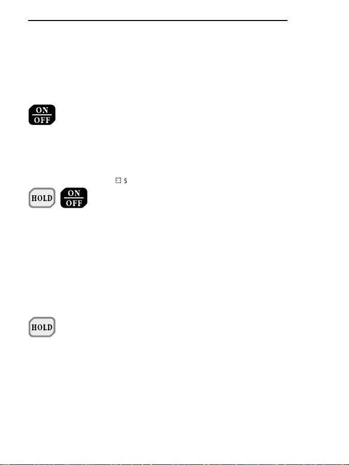
The REL key allows you to
display or store relative values or
send them immediately onto the
serial line.
The values for comparison are
stored at the precise moment in
which the key is pressed.
Data may be stored when the
REL button is active.
After data has been sent onto the
serial line, in immediate or remote
mode from the instrument’s internal memory, obtained with the
REL function active, a report will
be provided giving the maximum,
minimum and mean relative
values and the reference values
on which the calculation of the
relative values was based.
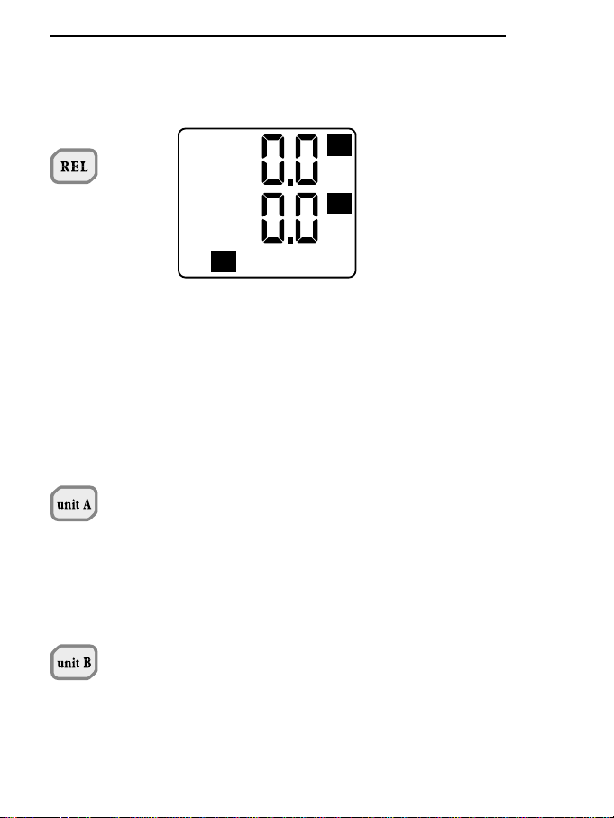
When the Unit A key is pressed,
input A, any of the following measurement units may be chosen:
kPa, bar, mmHg, atm, mmH2O,
psi, l/m, IGPM. The led corresponding to the unit chosen lights
up. The indication at the top of the
display corresponds to input A.
When the Unit B key is pressed,
input B, any of the following measurement units may be chosen:
kPa, bar, mmHg, atm, mmH2O,
psi, l/m, IGPM. The led corresponding to the unit chosen lights
up. The indication at the top of the
display corresponds to input B.
REL
3
10
3
10
Page 8
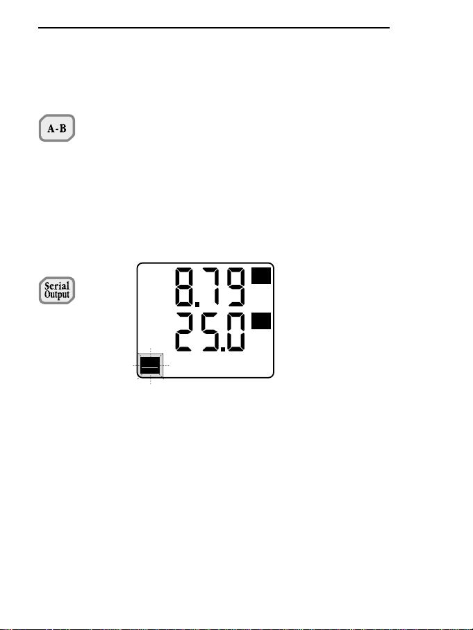
A-B
SERIAL OUTPUT
ENGLISH
72
KEY SIMBOLS LIT BESIDES
THE NUMBERS
FUNCTION
DESCRIPTION
Pressing A-B obtains the difference between the values indicated
for input A minus the values of
input B. The full-scale value of
the two probes must be the
same and they must be operating with the same measurement units, otherwise an ERR
message is given. The value of
the difference appears at the bottom of the display.
Serial Output key. The Serial
Output key sends the data being
acquired onto the serial line
immediately, according to the set
programming parameters. The
Serial Out symbol flashes.
Note:
The choice of the Baud Rate
influences the speed at which the
data are sent onto the serial line.
With a data transmission speed of
300 Baud (the character being
composed of 10 bit: 1 start bit + 8
character bit + 1 stop bit), the time
taken to send 80 characters on
the serial line is: 80 / (300/10) =
2.7 sec.
Serial
Out
Memory
3
10
3
10
Page 9
ENGLISH
73
KEY SIMBOLS LIT BESIDES
THE NUMBERS
FUNCTION
DESCRIPTION
P0+
+
+
There is therefore a limit on the
minimum time that may be set as
a function of the Baud Rate chosen:
- P0 -
When ENTER is pressed with P0
on the display, the instrument
returns to normal operating mode
without storing any parameter.
Press the PROG key to move on
to step P1.
When the skey is pressed with
P0 on the channel A display it
resets the offset of the connected
probe (only for probes for relati-
ve or differential measurements).
When the tkey is pressed with
P0 on the channel B display it
resets the offset of the connected
probe (only for probes for relati-
ve or differential measurements).
BAUD
RATE
300 Baud
600 Baud
> 600 Baud
MINIMUM
SETTABLE
TIME
4 sec.
2 sec.
1 sec.
Page 10
ENGLISH
74
KEY SIMBOLS LIT BESIDES
THE NUMBERS
FUNCTION
DESCRIPTION
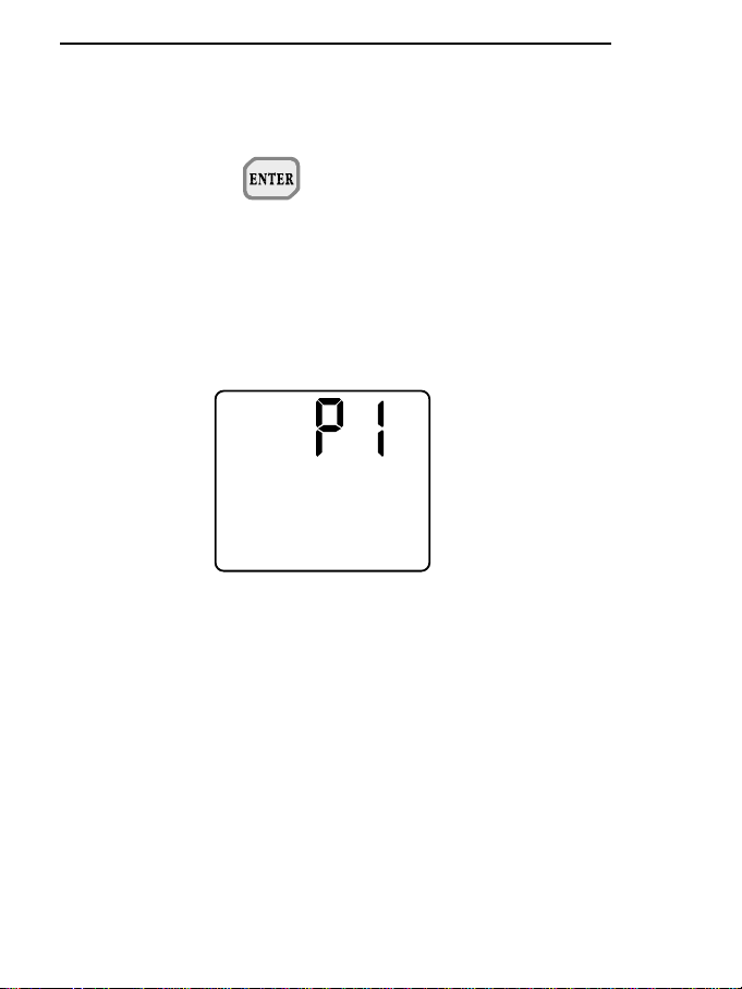
P1+ = data dump
- P1 -
When ENTER is pressed with P1
on the display, the data stored in
the memory of the instrument are
unloaded (DUMP); press the
PROG key to move on to step P2.
During data dumping the message P1 appears on the upper
display of the instrument. At the
end the instrument automatically
returns to normal operating mode.
The unloading of data from the
instrument memory may be
momentarily stopped by pressing
the ENTER key. Press the
ENTER key again to reactivate
data unloading.
When the PROG key is pressed,
data unloading is finally concluded.
At the end of each block the
report is sent with the maximum
(peak), minimum and mean
values calculated on the block.
During the DUMP phase the
instrument does not switch off
automatically, all the key functions
are disabled except the ENTER,
PROG and ON/OFF keys.
Note:
The block is defined at the
moment of storage as a group of
consecutive recordings. The first
interruption of storage ends and
determines the block.
Page 11
ENGLISH
75
KEY SIMBOLS LIT BESIDES
THE NUMBERS
FUNCTION
DESCRIPTION
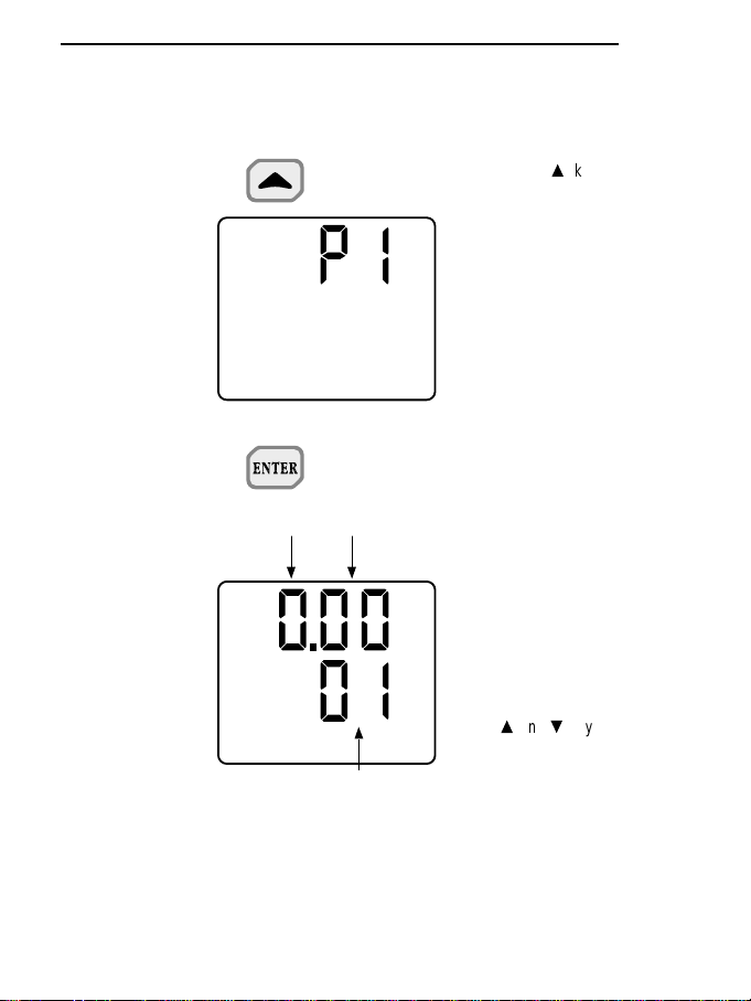
When the skey (MEMORY
CLEAR sub-function) is pressed
with P1 on the display, all the stored data are erased.
The instrument will display the
message P1. At the end the
instrument automatically returns
to normal operating mode.
- P2 -
When ENTER is pressed with P2
on the display, the storage time
parameter may be modified.
This parameter is used for the following two functions:
1. Logging time, or time elapsing
between two consecutive data
storages in the internal memory
of the instrument.
2. Data dump interval, or time elapsing between two immediate
data dumps on the serial line.
The sand tkeys are used to
define the desired intervention
time.
At bottom right of the display the
instrument indicates the seconds
(1 - 59).
At top right of the display the
instrument indicates the minutes
(1 - 59).
At top left of the display the instrument indicates the hours (1 - 12).
P1+ = erase memory
storage
P2+ = interval
programming
hours minutes
seconds
Page 12
ENGLISH
76
KEY SIMBOLS LIT BESIDES
THE NUMBERS
FUNCTION
DESCRIPTION
After defining the storage time,
press ENTER to return to normal
operation, or press the PROG key
to move on to step P3.
In the storage function the instrument is able to store more than
30,000 acquisitions.
The indicative time taken to fill the
memory completely is a function
of the recording interval and may
be obtained from the following
table:
Once the memory has been filled
the instrument automatically stops
and quits storage status. The flashing FUL message appears. The
instrument switches off after 8
minutes.
RECORDING INTERVAL
1 sec
1 min
1 hour
TIME TO FILL
THE MEMORY
8 hours
20 days
1250 days
Page 13
ENGLISH
77
KEY SIMBOLS LIT BESIDES
THE NUMBERS
FUNCTION
DESCRIPTION
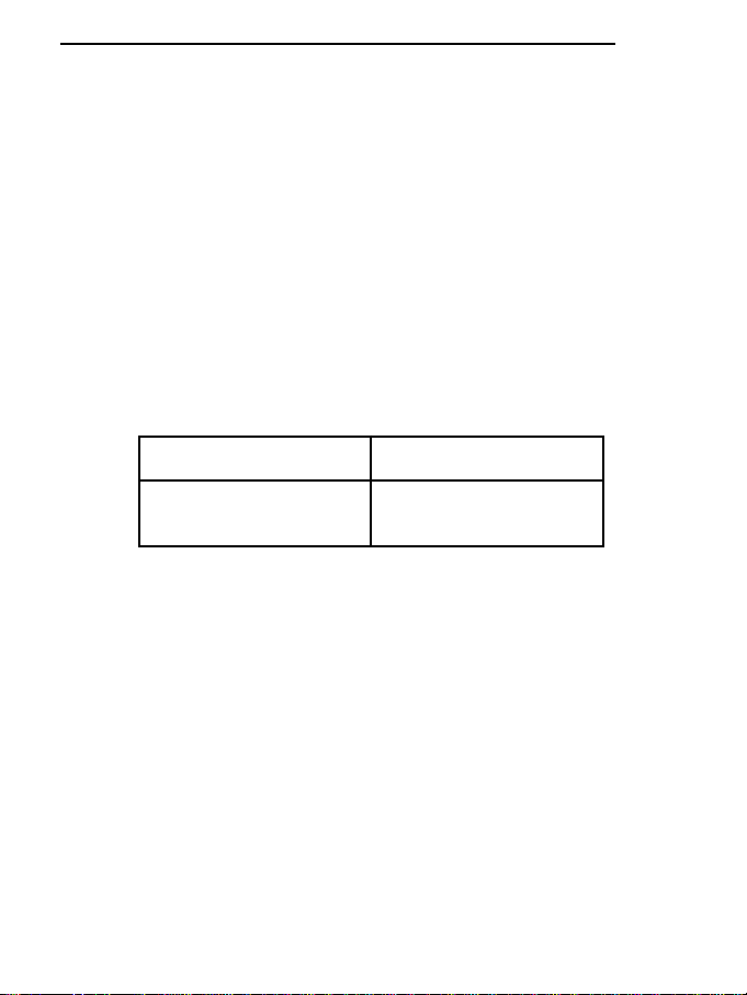
P3+ = set Baud Rate
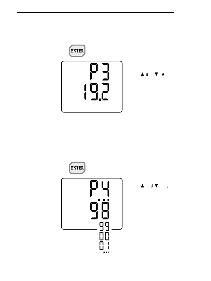
P4+ = set year
- P3 -
When ENTER is pressed with P3
on the display, the Baud Rate of
the RS 232C serial transmission
may be modified.
The sand tkeys are used to
select the desired value.
The possible values are:
19.2 = 19200 Baud
9.6 = 9600 Baud
4.8 = 4800 Baud
2.4 = 2400 Baud
1.2 = 1200 Baud
0.6 = 600 Baud
0.3 = 300 Baud
Finally press ENTER to return to
normal operation, or press the
PROG key to move on to step P4.
- P4 -
When ENTER is pressed with P4
on the display, the year value may
be set or changed.
The sand tkeys are used to
select the desired year.
Then press PROG to move on to
step P5 (the ENTER key is not
active).
Page 14
ENGLISH
78
KEY SIMBOLS LIT BESIDES
THE NUMBERS
FUNCTION
DESCRIPTION
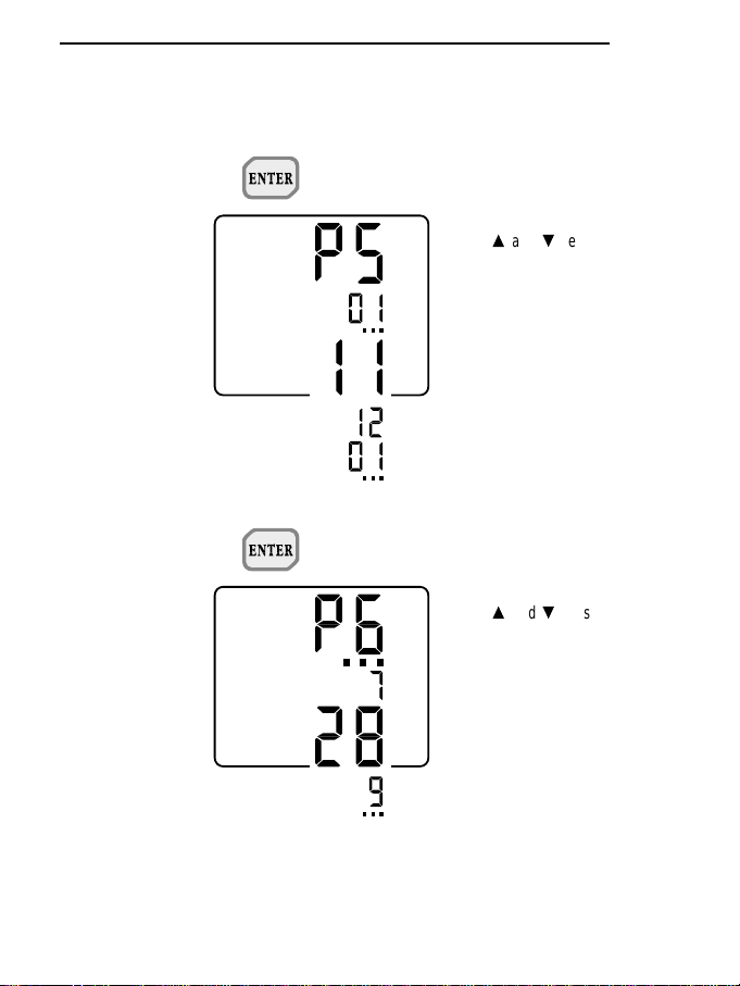
P5+ = set month
P6+ = set day
- P5 -
When ENTER is pressed with P5
on the display, the month may be
set or changed..
The sand tkeys are used to
select the desired month.
Then press PROG to move on to
step P6 (the ENTER key is not
active).
- P6 -
When ENTER is pressed with P6
on the display, the day may be set
or changed.
The sand tkeys are used to
select the desired day.
Then press PROG to move on to
step P7 (the ENTER key is not
active).
Page 15
ENGLISH
79
KEY SIMBOLS LIT BESIDES
THE NUMBERS
FUNCTION
DESCRIPTION
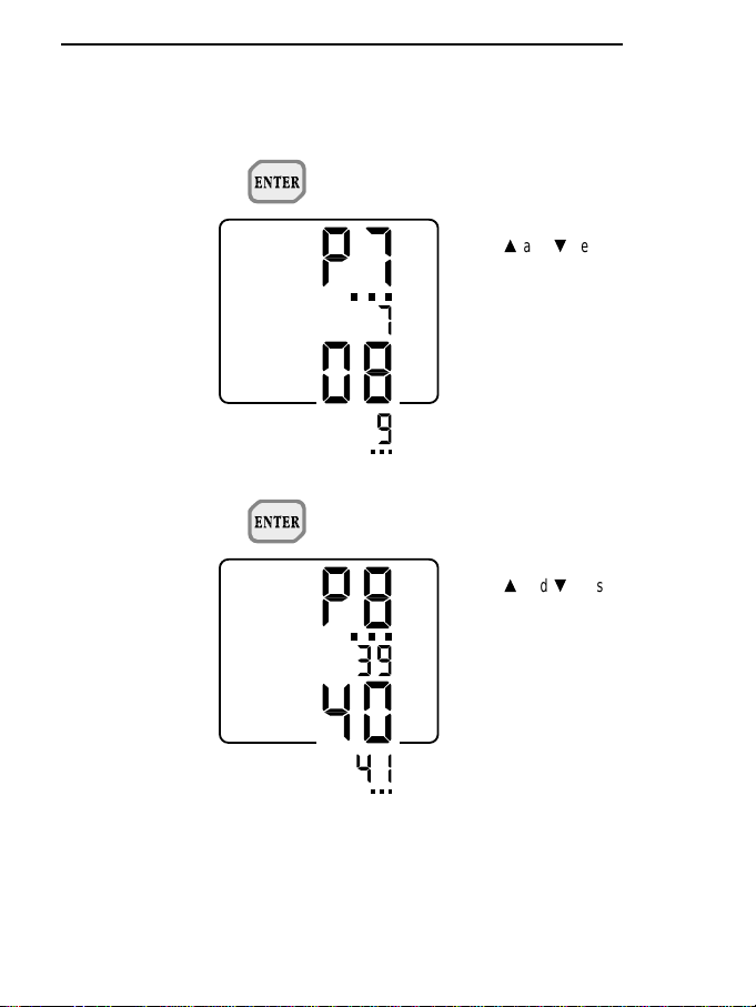
P7+ = set hours
P8+ = set minutes
- P7 -
When ENTER is pressed with P7
on the display, the hour may be
set or changed.
The sand tkeys are used to
select the desired hour.
Then press PROG to move on to
step P8 (the ENTER key is not
active).
- P8 -
When ENTER is pressed with P8
on the display, the minutes may
be set or changed.
The sand tkeys are used to
select the desired minutes.
Then press ENTER to return to
normal operating mode or PROG
to move on to step P9, without
updating the internal clock.
Quitting with the ENTER key
updates the internal clock with
the date and time just set, setting the seconds at zero at the
time of quitting.
Page 16
ENGLISH
80
KEY SIMBOLS LIT BESIDES
THE NUMBERS
FUNCTION
DESCRIPTION
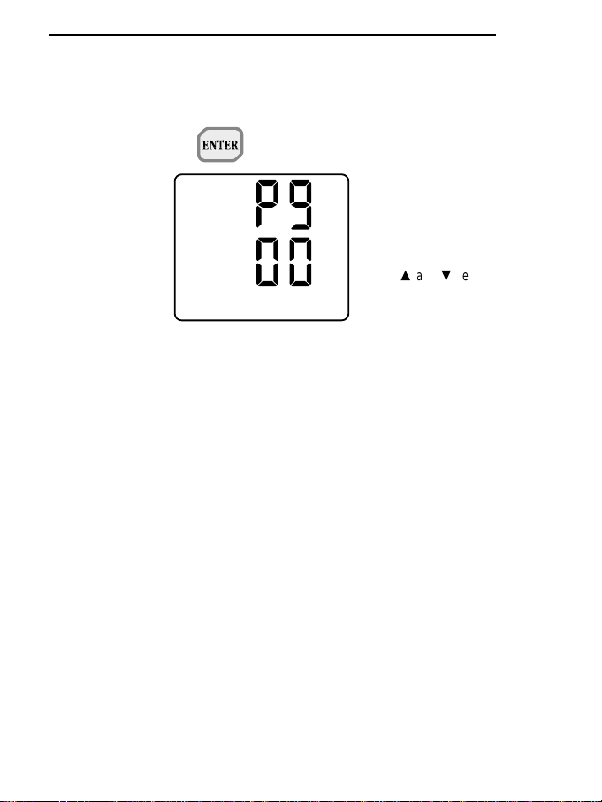
P9+ =
enable/disable
self cut-out
- P9 -
When ENTER is pressed with P9
on the display, the instrument
enters the program which enables
or disables the self cut-out function when it is in storage mode
and with a set storage interval
higher than or equal to 1 minute.
The sand tkeys are used to
select the value 00 or 01.
00 With a set storage interval
lower than 1 minute, the
instrument does not switch off
automatically; it always
remains lit.
When the ON/OFF key is
pressed, storage stops and
the instrument switches off.
00 With a set storage interval
higher than 1 minute, the
display switches off automatically after about 8 minutes. At
each set storage interval there
is a beep and the display switches on for a few seconds..
The display can be switched
on or off by pressing the
ON/OFF key. The instrument
keeps on storing if you keep it
switched on. The display switches off automatically after
about 8 minutes.
To stop storage, press the
ON/OFF key (if the instrument
is off). Press the ENTER key.
01 With a set storage interval
lower than 1 minute, the
instrument does not switch off
Page 17
ENGLISH
81
KEY SIMBOLS LIT BESIDES
THE NUMBERS
FUNCTION
DESCRIPTION
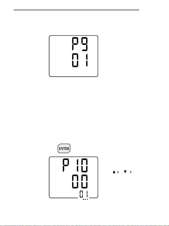
P10+ =
select type
of printing
automatically.
When the ON/OFF key is
pressed, storage is interrupted
and the instrument switches
off.
01 With a set storage interval
higher than 1 minute, the
display does not switch off
automatically; it remains
always lit and goes on storing.
When the ON/OFF key is
pressed the display stops till
the next acquisition. Then it
switches on again and
remains lit.
To stop storage, press the
ENTER key.
The ENTER key is used to return
to normal operating mode, while
pressing the PROG key moves on
to step P10.
- P10 -
When ENTER is pressed with
P10 on the display it is possible to
select complete or reduced data
printing.
The sand tkeys are used to
select the desired printing format.
01: complete printing
00: reduced printing
The ENTER key is used to return
to normal operating mode, while
pressing the PROG key moves on
to step P11.
Page 18
ENGLISH
82
KEY
SIMBOLS LIT BESIDES
THE NUMBERS
FUNCTION
DESCRIPTION
DATA CALL
P11+
- P11 -
When ENTER is pressed with
P11 on the display, the instrument
enters the program for calibrating
the instrument.
DATA CALL key (Mean - Max Min).
When the DATA CALL key is
pressed repeatedly, the Max
(Peak), Min and Mean values
measured for both measuring
channels are shown on the
display.
s
key. When enabled it increases
the values, in function P0 it
resets the probe offset of channel A (only for relative or differen-
tial probes), with P1 it enables the
memory clear function.
ENTER key (Start-Stop sub-function).
The ENTER key is used alternatively to start or stop storage of a
new block of data to be kept in the
memory of the instrument. Data
storage is performed at the rate
set during programming of step
P2.
The data stored between one
start and the following stop form a
block.
+ Start-Stop
3
10
3
10
3
3
10
10
3
10
3
10
MIN
3
10
3
10
Memory
MAX
MED
Serial
Out
Page 19

ENGLISH
83
KEY SIMBOLS LIT BESIDES
THE NUMBERS
FUNCTION
DESCRIPTION
Different blocks can thus be formed, all ending (during unloading)
with the report giving the maximum, minimum and mean values.
The Serial Out/Memory symbol
remains lit for the whole storage
period. The Auto Power Off function is active and the instrument
switches itself off after about 8
minutes of inactivity. It is restarted
automatically by the clock interrupt control which reactivates the
instrument for only the time needed for all the acquisition and storage operations. Once this has
been done the instrument switches itself off again.
During this phase the instrument
appears to be off, but it is active in
operating mode.
If the Serial Out/Memory symbol
lights up when switching on the
instrument with the ON/OFF key,
this means that the instrument
was in storage status.
In this stage the Serial Out and
PROG keys are not enabled.
When this operative mode
is disactivated the Serial
Out/Memory symbol is not lit.
The total memory capacity available is 512 kbyte, with the possibility of storing more than 30,000
readings.
Page 20
ENGLISH
84
KEY SIMBOLS LIT BESIDES
THE NUMBERS
FUNCTION
DESCRIPTION
ENTER
with RCD
During programming this key is
used both to enter the desired
program and to confirm the value
of the parameter considered.
When pressed repeatedly, the
t
key, sub-function RCD, starts and
stops the record function, which
calculates and stores the maximum, minimum and mean values.
When the RCD key is held down
the instrument emits a short beep
followed by a long one. This confirms that the max., min. and
mean values stored previously
are being erased from the
memory and a new series of
recordings is started which will be
used as the basis on which to calculate and store new max., min.
and mean values
After resetting of the max., min.
and mean values, the RCD function has a duration of about
30,000 readings, that is about 4
hours. At the end, the RCD function is automatically interrupted
and the max. min. and mean
values calculated up till then are
maintained.
During RCD mode the Auto
Power Off function is disabled and
the battery symbol flashes at a
frequency of 2 Hz.
Attention:
If the battery symbol does not fla-
10
3
3
10
Page 21

ENGLISH
85
KEY SIMBOLS LIT BESIDES
THE NUMBERS
FUNCTION
DESCRIPTION
sh at a frequency of 2 Hz when
the RCD key is pressed, it means
that the RCD function has stored
more than 30,000 acquisitions
and cannot continue any further.
After having taken note of the
max. min. and mean values calculated up till then, reset the RCD
function and restart it.
t
key. During programming or
calibration, this key is used to
decrease the value of the parameter being considered. In func-
tion P0 it resets the probe offset of channel B (only for relative
or differential probes).
Page 22

PROBE CONNECTION
One or two pressure probes, one or two temperature probes may be connected to the DO 9704
pressure and temperature gauge - data logger. The pressure probes of the TP 704 series have a
1/4” BSP male threaded coupling and must be screwed into the fitting in which the pressure is to be
measured; the probes of the TP 705 series have a ∅ 5 mm. coupling to which will be connected a
suitable tube for taking the desired measurement; take great care with the pressure seal of the
fitting, if necessary using gaskets and suitable fittings. The threaded coupling is protected by a plastic cap; put the cap back after use, as it protects the pressure cell against foreign bodies. IT IS
VERY IMPORTANT to ensure that the full scale value of the probe is higher than the pressure that
is to be measured. If you do not know the value, start off using probes with high capacities. Using
the CPA cable, connect the pressure probe to the instrument and then take the measurement. The
same operations are carried out when using two temperature probes at the same time. The temperature probe must be connected to input A or B of the instrument or to both if there are two probes;
then measure the temperature with the sensitive part of the probe. Depending on the case, immersion, contact, penetration or air probes will be used.
The same applies to probes for measuring flow rate; in this case ensure that the connection cable
is specifically configured for the flow rate or for the number of impulses of the turbine.
HOW TO MEASURE
1. Press the ON/OFF key to switch on the instrument.
* This operation enables the automatic cut-out timer.
If you wish power supply without automatic interruption, when switching on, press the HOLD
and ON/OFF keys simultaneously and keep the HOLD button held down for the duration of the
switching-on routine. The battery symbol flashes at a frequency of 1 Hz, indicating that the Auto
Power Off function is disabled.
* When the instrument is switched on all the numbers and symbols light up for a few moments,
allowing you to check that all the display segments are working.
* After a few moments it moves on to normal operation.
2. Checking display.
* After all the segments are lit, the instrument is ready to measure in the engineering unit (Pa,
bar, psi, atm, mmHg, mH2O) set before the instrument was switched off.
* If a probe is broken or is not properly connected, the Err signal appears. In this case the sensor
part and/or the connector must be checked.
3. Selection of the measuring unit.
* Press the Unit A key repeatedly to show, at the top of the display, the measurement of the pro-
be connected to input A in the desired measuring unit; press the Unit B key repeatedly to show,
at the top of the display, the measurement of the probe connected to input B in the desired
ENGLISH
86
Page 23

measuring unit.
* Press the Unit A or B key to select the temperature measuring unit in °C or °F.
4. Switching off the instrument.
* The instrument is switched off by pressing the ON/OFF key.
* Because of the Auto Power Off function the instrument may switch itself off during measure-
ments. In this case press the ON/OFF key to switch it on again.
* The instrument usually switches off automatically after 8 minutes of inactivity, with the following
exceptions:
a) Instrument in RCD status.
b) Instrument in Auto Power Off Disabled status.
In these two cases the instrument switches off only when the ON/OFF key is pressed.
c) Instrument during unloading of stored data.
d) Instrument during Serial Output of immediate data.
e) Instrument in storage function.
In the last three cases the instrument switches off automatically 8 minutes after the low
battery warning and interrupts storage and unloading of data.
When it switches on again there are two possibilities:
1. If the battery is definitively low, even when the instrument switches on again LOU appears on
the display together with the battery symbol.
The PROG key (P1+ENTER) enables the activation of the unloading of stored data even
when the battery is low.
2. If the battery has had time to recover and when the instrument switches on its charge seems,
even just a little, higher than the minimum value, LOU appears on the display without the battery symbol for a short period of time (about 4 seconds), after which the instrument returns to
normal operation; this is to remind the user that the instrument was previously in storage function and that this procedure was interrupted by the low battery warning.
5. Various operations.
* For operations such as HOLD display, relative measurements, RCD storage, DATA CALL,
Serial Output, storage in the internal memory, unloading of stored data, erasing of the internal
memory, setting of the working parameters, see the description of the instrument keyboard.
Attention when using the keyboard
The use of the keys is relatively simple, but care must be taken to avoid setting it by mistake in an
undesired mode. Ensure that HOLD, RCD, REL, MAX, MIN, MED, Serial Out/Memory are not
displayed during normal operation.
ENGLISH
87
Page 24

TEMPERATURE MEASUREMENT
Immersion temperature measurements are performed by introducing the probe to a minimum
depth of 60 mm into the liquid in which you want to take the measurement; the sensor is housed in
the end of the probe.
To take measurements in air, the probe must be pointed in a transverse direction to the air flow.
In both cases, to ensure correct measurement avoid contact of the probe with the walls of the container holding the liquid or of the duct in which the air to be measured is passing.
When taking penetration measurements the tip of the probe must be inserted at a depth of at least
60 mm; the sensor is housed in the end of the probe. When taking measurements on frozen blocks
it is convenient to use a mechanical tool to make a cavity in which to insert the pointed probe.
To perform a contact measurement correctly the surface must be flat and smooth and the probe
must be perpendicular to the measuring plain.
To obtain a correct measurement, the application of a little heat-conductive paste or a drop
of oil (water or solvents must absolutely not be used) helps to improve the response time.
METHOD OF USING THE INSTRUMENT AND WARNINGS
1. Do not expose the probes to gases or liquids that could corrode the material of the sensor or
the probe; clean the probe carefully after use.
2. Do not bend the connectors applying upward or downward force.
3. Do not bend or force the contacts when inserting the probe connector in the instrument.
4. Do not bend, deform or drop the probes as this could cause irreparable damage.
5. Always use the most suitable probe for the measurement to be taken.
6. Be careful with the range of use of the probe, measurements at limit values are possible only
for short periods.
7. Do not use the temperature probes in the presence of corrosive gases or liquids; the container
in which the sensor is housed is made of stainless steel AISI 316, while the container for the
contact probe is of AISI 316 plus silver. Do not let the surfaces of the probe come in contact
with sticky surfaces or with substances that can corrode or damage the probe. If the sensor
breaks or becomes faulty it must be replaced. In this case the probe must be recalibrated.
8. Above 400°C, avoid violent blows or thermal shock to the Pt100 temperature probes as these
could cause irreparable damage.
9. To obtain a reliable temperature measurement, too fast temperature variations must be avoided.
10. Temperature probes for surface measurements must be held in a vertical position with respect
to the surface. Apply a drop of oil or heat-conductive paste between the surface and the sensor
so as to improve contact and reduce the reading time. Do not use water or solvents to do this.
11. Temperature measurements on non-metal surfaces require a great deal of time on account of
ENGLISH
88
Page 25

their low heat conductivity.
12. The probes are not insulated from their external casing. Be very careful not to come
into contact with live parts (above 48V) as this could be dangerous not only for the
instrument but also for the operator, who could suffer an electric shock.
13. Avoid taking measurements in the presence of high frequency sources, microwaves or large
magnetic fields, as the results would not be very reliable
14. Always clean the probes carefully after use.
15. After taking a pressure measurement, clean the probe pressure chamber accurately; do not let
the fluid that comes in contact with the membrane leave any deposits or scale, with time these
could cause errors in measurement.
16. Avoid inserting sharp points or nails in the pressure chamber; a sudden blow could accidentally
break the membrane.
17. To secure the probes use a suitably sized spanner and, if necessary, sealing gaskets.
18. Great care must be taken when installing probes in pressurised containers or in
pipes. Take care when choosing the full scale range of the probes. Apart from causing irreparable damage to the probe, an error could cause quite serious physical
harm to the operator and to objects in the vicinity. There should always be a stop key
upstream from the probe. Ensure that there are no abnormal and sudden variations
in the fluid under pressure.
19. The instrument is resistant to water but it is not watertight and should not therefore be immersed in water. If it should fall into the water, take it out immediately and check that no water has
infiltrated. The instrument must be handled in such a way that water cannot get in through the
connector side.
INSTRUMENT SIGNALS AND MALFUNCTIONS
ENGLISH
89
Err On the upper display indicates:
* Error in reading the signal present at input A or B or A-B;
* Error when, with A-B, the probes inserted do not have the same full scale value and
are not of the same type.
FUL Memory full.
LOU When switching on this indicates that the instrument has switched off because the bat-
tery voltage was too low when it was in storage or serial output status. Change the battery even if there are no low battery signals.
Page 26

LOW BATTERY WARNING AND BATTERY REPLACEMENT
When the battery has run down and its voltage has reached the limit value of 7.2 Volts, the symbol
H
appears permanently on the display and an alarm beep sounds at regular intervals of about 15
seconds. In these conditions the battery should be replaced as soon as possible.
If you continue to use the instrument and the battery voltage falls as low as 6.5V the instrument is
no longer able to ensure correct measurement.
AFTER CHANGING THE BATTERY YOU MUST UPDATE THE CLOCK AND THE SET PARAMETERS.
To change the battery turn the instrument retaining screw in an anti-clockwise direction. After replacing it (with an ordinary 9V alkaline battery) close the instrument, inserting the tag into the slot provided, and turn the screw in a clockwise direction.
The stored data will not be lost even if the instrument remains without batteries as long as the
working routines have been completed.
Ensure that the instrument is switched off before changing the battery.
The symbol Happears fixed to indicate that the battery is low. This indication prevails over all the
other signals which make use of the symbol
H
. In RCD function the symbol Hflashes at a fre-
quency of 2 Hz. In Auto Power Off function the symbol
H
flashes at a frequency of 1 Hz. The fla-
shing of the RCD function prevails over the flashing of Auto Power Off.
ENGLISH
90
Page 27

FAULTY OPERATION WHEN SWITCHING ON AFTER CHANGING THE
BATTERY
Repeat the battery changing procedure, waiting for a few minutes to allow the circuit condenser
capacities to be completely discharged, then insert the battery.
WARNING ON USE OF THE BATTERIES
* If the instrument is not to be used for a long time the battery must be removed.
* If the battery is flat it must be replaced immediately.
* Take steps to avoid leakage of liquid from the battery.
* Use good quality leakproof batteries, alkaline if possible.
STORAGE OF THE INSTRUMENT
Instrument storage conditions:
* Temperature: -10...+50°C.
* Humidity: less than 90% relative humidity, avoid the formation of condensation.
* Do not store the instrument in places where:
1. There is a high degree of humidity.
2. The instrument is exposed to direct sunlight.
3. The instrument is exposed to a source of high temperature.
4. There are strong vibrations.
5. There is steam, salt and/or corrosive gas.
The instrument body is made of ABS plastic so it must not be cleaned with solvents which can spoil
plastic.
SERIAL INTERFACE RS 232C
The instrument is equipped with the standard serial interface RS 232C, galvanically insulated;
it is supplied with the adapter cable CP RS 232C. The following signals are available on the
SUB D 9-pin male connector of the instrument:
NOTE: The deflector on the connector of the adapter cable CP RS 232C must be turned to COM-
PUTER or PRINTER position, depending on the chosen connector (this may not be true on
some computers or printers).
The signals present in pins 2 and 3 are at logic levels compatible with the standard RS 232C.
ENGLISH
91
PIN SIGNAL DESCRIPTION
3 TD Datum transmitted by the instrument
2 RD Datum received by the instrument
5 GND Reference logic mass
Page 28

The transmission parameters with which the instrument is supplied are:
* Baud Rate 19200 Baud
* Parity None
* N. bit 8
* Stop bit 1
* Protocol Xon/Xoff
The data transmission speed may be changed by pressing the PROG key on the instrument to alter
the set-up parameter P3. The possible Baud Rates are: 19200, 9600, 4800, 2400, 1200, 600, 300.
The other transmission parameters are fixed.
All the messages reaching and leaving the instrument must be inserted in a “Communication frame” with the following structure:
Record-cr
where:
-Record- constitutes the message
-cr- Carriage Return (ASCII 0D)
HOST COMMANDS
COMMAND TYPE REPLY
AA Type of terminal MANOMETER – DL
AG Firmware Version Vx Rx
AH Firmware Date dd/mm/yy
A* ?
SA Request Input A
SB Request Input B
SC Request Input A-B
SI Measurement MANOMETER - DL
S* NC
It is possible to unload data onto a computer using the Xon/Xoff protocol to control the data flow:
The character Xoff (hex 13) on the serial line stops the data unloading in progress.
The character Xon (hex 11) reactivates the suspended data unloading in progress.
Dumping data from the memory
Press the PROG key twice until P1 appears on the display.
Press the ENTER key.
The instrument continues to show P1 on the display and dumps the data from the instrument’s
internal memory through the serial line.
ENGLISH
92
Page 29

At the end of data dumping the instrument returns to normal display.
It is possible to stop and resume data dumping by repeatedly pressing the ENTER key.
Once data dumping has been stopped it may be terminated by pressing the PROG key.
Memory clear
Press the PROG key twice until P1 appears on the display.
Press the skey (memory clear sub-function).
The instrument will erase the internal memory, showing P1 on the display.
At the end of the operation the instrument returns to normal display.
ENGLISH
93
COMPUTER PRINT
COMPUTER
PRINT
NC
NC
NC
NC
TEST
NC
NC
6789
RTS
RXD
CTS
DSR
DCD
GND
NC
RC
NC
NC
NC
NC
DTR
12345678910111213
141516171819202122232425
NC
TXD
SCR
12345678910111213
14 15 16 17 18 19 20 21 22 23 24 25
TC
NC
12345
Page 30

ENGLISH
94
DIAGRAM DO 9704
Probe A
Probe B
PRINTER
WITH SERIAL
Pressure or temperature
Pressure or temperature
INPUT
SERIAL/
PARALLEL
CONVERTER
PRINTER
WITH PARALLEL
INPUT
Page 31

EXAMPLE OF A REPORT PRINTED BY THE INSTRUMENT
ENGLISH
95
Page 32

ENGLISH
96
Page 33

INSTRUCTIONS FOR CONNECTING DELTA OHM INSTRUMENTS TO A PC
WITH WINDOWS OPERATIVE SYSTEM
Hardware connection:
1. The measuring instrument must be switched off.
2. Connect the serial gate of the measuring instrument to a free serial gate on the PC
(COM1/COM2) using the special Delta Ohm CP RS 232C cable.
Note: the CP RS 232C cable ends in a female 25-pin connector; if your PC does not have a
compatible connector, use the adapters normally found on the market to make the connection.
3. Turn the switch on the CP RS 232C cable to COMPUTER position.
Software connection with WINDOWS 3.1:
A) Start WINDOWS
B) Select ACCESSORIES (double click)
C) Select TERMINAL and activate the communications program (double click)
ENGLISH
97
Page 34

D) To alter the communication settings of the terminal, in order to make them compatible with those
of the measuring instrument used (unless a terminal setting file has already been saved):
select SETTINGS in the terminal window (one click)
select COMMUNICATIONS from the menu (one click)
the COMMUNICATIONS window for setting the communication procedures will appear on
the screen; set:
TRANSMISSION SPEED: 19200 which must correspond to the speed set on the instrument (one click)
DATA BITS: 8 (one click)
STOP BITS: 1 (one click)
PARITY: None (one click)
FLOW CONTROL: Xon/Xoff (one click)
CONNECTOR: COM1 or COM2 depending on the gate used for connection (one click)
CHECK PARITY and SHOW CARRIER must remain unmarked
OK to confirm the setting (one click)
ENGLISH
98
Page 35

E) To set the correct character type:
select SETTINGS from the terminal window (one click)
on the pull-down menu select TERMINAL PREFERENCES... (one click)
the TERMINAL PREFERENCES window appears on the monitor, set:
Mark local Echo (one click)
Character type: Terminal (or equivalent)
Leave the rest unchanged
OK to confirm the setting (one click)
ENGLISH
99
Page 36

F) If you want to save this terminal setting:
select FILE from the terminal window (one click)
select SAVE AS from the pull-down menu and the SAVE FILE AS window will appear (one
click)
type the name of the terminal setting file (max. 8 characters) on the line provided
OK to confirm and save the setting (one click)
ENGLISH
100
Page 37

G) To receive and store data from an instrument:
select TRANSFER from the terminal window (one click)
select RECEIVE TEXT FILE from the pull-down menu and the window will appear (one click)
type the name of the file in which data are to be stored (max. 8 characters) on the line
provided
OK to confirm and start storage (one click)
At this point the terminal is ready to receive data from the measuring instrument. Everything sent
by the measuring instrument will be stored in the file indicated previously
ENGLISH
101
Page 38

H) Switch on the measuring instrument
When the instrument has completed the switching-on routine, activate the immediate unloading
of data at the set rate, pressing the SERIAL OUTPUT button, or activate the unloading of the
data stored in the internal memory with the program P1 (press the PROG button twice) and
press the ENTER button.
I) End of storage of the data sent by the instrument
select TRANSFER from the terminal window (one click)
to end storage, select END from the pull-down menu (one click)
The software returns to the terminal window
L) End use of the TERMINAL:
select FILE from the terminal window (one click)
select QUIT from the pull-down menu (one click)
The text file, containing the data received from the measuring instrument connected to the PC, is
now stored in our computer. To read and process the file obtained we can use any text or table processing program in the Windows environment (WORD, EXCEL, WORKS, etc.)
ENGLISH
102
Page 39

Software connection with WINDOWS 95.
A) After starting WINDOWS 95, select START, PROGRAMS, ACCESSORIES, HYPERTERMINAL.
Run HYPERTRM (double click)
B) Name of the communication
In the window “Description of connection”, give a name to the communication that you want to
activate and choose an icon (in subsequent communications it will be possible to activate directly the icon chosen in place of HYPERTRM, automatically recovering all the settings saved with
the icon).
OK to confirm
Cancel in the next window
ENGLISH
103
Page 40

C) Setting communication
- select FILE from the Hyper Terminal window (one click)
- select PROPERTIES from the pull-down menu (one click) and the “Properties” window will
appear
- on the “telephone number” card, for the Connect property, choose “directly to COM1” or
“COM2”, depending on the serial gate that you intend to use for communication with the measuring instrument
- on the “telephone number” card, select CONFIGURE (one click) and the “Gate settings” card
will appear
- on the “Gate settings” card select:
BITS PER SECOND: 19200
DATA BITS: 8
PARITY: None
STOP BITS: 1
FLOW CONTROL: Xon/Xoff
OK to confirm the gate setting (one click)
ENGLISH
104
Page 41

ENGLISH
105
Page 42

- select SETTINGS to display the “Settings” card
- on the “Settings” card, for the “Emulation” property, select: TTY
- OK to confirm the “Properties” set (one click)
ENGLISH
106
Page 43

D) To set the correct character type:
- select DISPLAY from the Hyper Terminal window (one click)
- select CHARACTER from the pull-down menu (one click) and the window for selecting the character will appear; set:
- Terminal (or equivalent)
- OK to confirm (one click)
ENGLISH
107
Page 44

E) To receive and store data from an instrument:
- select CALL from the Hyper Terminal window (one click)
- select CONNECT from the pull-down menu
- In this way it is possible to receive the characters from the instrument on the monitor
ENGLISH
108
Page 45

F) To receive and store data from an instrument:
- select TRANSFER from the Hyper Terminal window (one click)
- select CAPTURE TEXT from the menu (one click) and the window will appear where you have
to set the name of the file in which to store the data received from instrument
- type the name of the file in which data are to be stored on the line provided
- OK to set the name of the receiving file (one click)
At this point the Hyper Terminal software is able to receive data from the measuring instrument and
store them in the set file
ENGLISH
109
Page 46

G) To end receiving data from an instrument:
select TRANSFER from the Hyper Terminal window (one click)
select CAPTURE TEXT from the menu (one click)
select END from the pull-down sub-menu (one click)
At this point data reception from the instrument is ended and the file stored in the computer can be
used with any of the software packages used with WINDOWS 95.
H) To quit running the Hyper Terminal:
select FILE from the Hyper Terminal window
select QUIT from the pull-down menu
ENGLISH
110
Page 47

CALIBRATING THE INSTRUMENT DO 9704
Apply a voltage of 465.5 mVdc between pin 6 (GND) and pin 1 (OUT) of the DIN 8-pole connector
at input A.
Select step 11 with the PROG key; press the ENTER key, the display shows
Using the sand tkeys, make the value shown on the display coincide with 196.0. Confirm by
pressing the ENTER key; P11 appears on the display; press PROG: P0 appears; press ENTER:
this quits the instrument calibration function.
ENGLISH
111
Instrument
7
3
5
6
8
Vdc=465.5
1
4
DO 9704
BA
2
Page 48

FLOW RATE MEASUREMENTS
A selection resistance sets the conversion factor of the connected turbine.
The instrument automatically recognises 5 fixed flow rate values plus a sixth which may be configured by the user.
*The instrument can read a reduced measuring range, it has the same selection resistance.
The connection cable of the configurable turbine will end with a DIN 8-pole connector; connect a
121 kΩ resistance between pin 3 and pin 7.
Active probe for measuring flow rate with a turbine 2 to
2000 litres/minute.
*A coil which generates impulses with a minimum of
100 mV p-p is connected to pins 4 and 6.
ENGLISH
112
FLOW RATE PROBES
Measuring range Selection Output Indication
resistance kΩ frequency PPL lt/min.
LT 5 5 l/min. 90.9 5 5
(LT10)* 95.3 5 20
LT20 20 l/min.
(LT50)* 100 0.5 125
LT125 125 l/min.
(LT250)* 105 0.1 400
(LT300)*
LT400 400 l/min.
LT500 500 l/min. 110 0.04 500
LT750 750 l/min. 115 0.04 750
LT configurable 2000 l/max 121 configurable PPL
1
2
6
1
4
7
3
8
5
N.C.
N.C.
R. Select.
5 73 4 6
N.C.
8
N.C.
2
*
Page 49

Connect the probe to the turbine that you want to configure and switch on the instrument; the message PPL will appear on the display corresponding to input A or B.
Press the PROG key, P0 will appear on the display; using the
s
and tkeys, select the input to
which the turbine probe is connected; the previously set number of impulses per litre will appear on
the display. Using the sand tkeys, set the number of impulses per litre corresponding to the
number of impulses per litre of the turbine that is being configured. Confirm by pressing the ENTER
key; P0 appears on the display. Press ENTER: this quits the procedure for configuring a turbine
with any number of impulses per litre.
CONNECTION OF PROBES TO THE PRESSURE GAUGE DATA LOGGER
DO 9704
One or two pressure probes of the series TP 704 or TP 705 may be connected to the instrument,
one or two temperature probes of the series TP 870, turbine probes for measuring flow rate or
impulse probes for measuring flow rate.
Probe connection diagram
1° 500mV
^
–
F.S.Pressure
2° Reserved
3° JP2Configuration (Selec. R towards 7)
4° Flow rate input
5° Reserved
6° GND (Ref. Flow rate)
7° +5 Vdc
8° -5 Vdc~
ENGLISH
113
Instrument
BA
7
3
5
6
8
2
DO 9704
1
4
7
3
5
6
1
8
4
2
Page 50

ENGLISH
114
6
1
4
7
3
5
8
2
+5V
7
GND
6
OUT
2.375mV/°C
1
-5V
8
6
1
4
7
3
5
8
2
6
1
4
7
3
5
8
2
N.C.
1
N.C.
5 73 4 6
N.C.
R. Select.
2
N.C.
8
*
500mV
F.S. Pressure
1
N.C.4N.C.
5
GND
6
-5V
8
+5V
7
Probe series TP 704, TP 705
Turbine probe for measuring flow rate
Active probe Pt100
series TP 870
Active probe TP 704, TP 705 Active turbine probe for measuring
flow rate.
2 to 2000 litres/minute
* A coil which generates impulses with a
minimum of 100 mV p-p is connected
between 4 and 6.
Probe series TP 870
N.C.
2
R. Select.
Verso 7
3
SEL R. PPL Turbine
(WEBSTER)
90 k9 5
95 k3 5
100 k 0.5
105 k 0.1
110 k 0.04
115 k 0.04
Probe for measuring flow rate with impulses
6
1
4
1 43
2 7
121K3K9
N.C.
N.C.
Active probe with NPN output for measuring
flow rate with impulses
8
2
7
3
5
5
N.C.
ln4148
86
N.C.
Page 51

CLASSIFICATION OF PRESSURE MEASUREMENTS
Pressure measurements are relative and therefore refer to a reference pressure. There are four
types of pressure measurement which enable the reference pressure to be defined immediately.
- Absolute pressure (A) – Pressure with respect to absolute zero, the ideal vacuum reference; the
pressure measured is always higher than the reference pressure.
- Gauge (G) – Pressure measured with respect to atmospheric pressure, environment pressure is
the reference; the pressure measured is always higher than the reference pressure.
- Vacuum (V) – Pressure with reference to atmospheric pressure, environment pressure is the
reference; the pressure measured is always lower than the reference pressure.
- Differential pressure (D) – Pressure measured with respect to any reference pressure; the pressure measured may be higher or lower than the reference pressure.
ENGLISH
115
The case G is similar to the case D
where the reference P = atmospheric P
Absolute Relative
(GAUGE)
VACUUM
Vacuum
P. to be
measured
Absolute pressure A
Reference
P.
Differential
Atm. P.
Relative pressure (gauge) G
Differential pressure D
Atmospheric
pressure
Zero
pressure
P. to be
measured
P. to be
measured
Page 52

CONVERSION FACTORS AND TABLES
°F-32
Temperature: °C =
___________
; °F = (1.8 x °C) + 32
1.8
Pressure measurement: mm = 0.03937 in in = 25.4 mm
cm = 0.3937 in in = 2.54 cm
m = 39.37 in in = 2.54 x 10⁻²m
f force
p =
___________
= pressure =
___________
m
2
surface
According to the international system, pressure measurement is expressed in Pascal 1 Pa = 1 N/m
2
=
1 Newton/square metre.
The principal engineering units for measuring pressure are:
Pascal = Pa (N/m2), kPa = 103Pa, Mpa = 106Pa
Bar = bar, mbar = bar x 10
–3
Metres of column of water 4°C = mH
2
O, mmH2O = mH2O x 10
–3
Millimetres of column of mercury 0°C = mmHg, Torr
Theoretic atmosphere = at (kp/cm2)
Physical atmosphere = atm
Inches of column of water at 4°C = in H2O
Inches of column of mercury at 0°C = in Hg
Micro of column of mercury at 0°C = µm Hg
Pounds per square inch = psi
1 bar = 100,000 Pa Pa = 10–5x bar
1 bar = 14.5038307 psi psi = 0.0689473023 x bar
1 bar = 0.986923 atm atm = 1.01325 x bar
1 bar = 755.7299444 mmHg mmHg = 0.001323224 x bar
1 bar = 10.19716213 mH2OmH
2
O = 0.0980665 x bar
psi = in of H2O x (3.6127 x 10–2) in of H2O = psi x 27.68
psi = mm of H2O x (1.4223 x 10–3) mm of H2O = psi x 703.1
psi = cm of H2O x (1.4223 x 10–3) cm of H2O = psi x 70.3
psi = in of Hg x 0.49118 in of Hg = psi x 2.036
psi = mm of Hg x (1.9339 x 10⁻²) mm of Hg = psi x 51.71
psi = Kg/cm2x 14.223 Kg/cm2= psi x 0.0703
psi = bar x 14.503 bar = psi x 0.0689
psi = mbar x (1.4503 x 10⁻²) mbar = psi x 68.95
ENGLISH
116
Page 53

psi = Pa x (1.4503 x 10⁻⁴) Pa = psi x 6895
psi = kPa x (1.4503 x 10⁻¹) kPa = psi x 6.895
1 atm = 1,013 x 105Pa
1 bar = 1,000 x 105Pa
1 dyne/cm
2
= 1,000 x 10–1Pa
1 inch of Hg (0°C) = 3,386 x 103Pa
1 inch of H2O (4°C) = 2,491 x 102Pa
1 Kg/m
2
= 9,806 Pa
1 pound/inch2(psi) = 6,895 x 10
3
1 pound/foot
2
= 4,788 x 10
1
1 Torr (mm de Hg 0°C) = 1,333 x 10
2
ENGLISH
117
Page 54

ENGLISH
118
2
psi
Ipf / in
Microns
Hg
inch
O
2
H
inch
atm
2
at
kp / cm
Torr
mmHg
O
2
O mmH
2
mH
kPa MPa bar mbar
2
PA
N / m
–6
145.05
0.14505
45.05 - 10
6
7501
7.501
7.501 - 10
–4
295.3
0.2953
2.953 - 10
–3
4016
4.016
4.016 - 10
–3
9.869
9.869 - 10–69.869 - 10
–6
–3
10.20
10.20 - 10
10.20 - 10
–3
7501
7.501
7.501 - 10
3
102.0
0.1020
102.0 - 10
–3
102.0
0.1020
0.1020 - 10
4103
–2
10
10
10
–2
10
10–510
–610–3
1
10
3
–3
1
10
10
3106105
1
10
–3
14.505
14.505 - 10
3
750.1
750.1 - 10
–3
29.53
29.53 - 10
401.6
0.4016
–3
0.9869
0.9869 - 10
–3
1.020
1.020 - 10
750.1
0.7501
3
10.20
10.20 - 10
–3
10.20
10.20 - 10
1
–3
1
10
–4
0.1
10
0.1
100
100
–3
1.4224
–3
73.56 - 10
2.896
39.37
–3
96.78 - 10
0.1
73.56
–3
10
1
98.07
98.07 - 10–398.07 - 10–61.333 - 10
9.807 - 10–39.807 - 10
9.807
9807
14.224
0.01934
1.4224 - 10
–3
–3
10
73.56
735.6 - 10
–2
28.96
2.896 - 10–33.937 - 10
393.7
0.5351
0.03937
–3
0.9678
96.78 - 10–61.316 - 10
–3
–4
1
10
1.359 - 10
–3
1
735.6
73.56 - 10
4
1
10
13.59
–3
–3
10
10
13.59 - 10
–3
1.333
980.7
98.07 - 10
–3
0.9807
–6
–6
–3
98.07 - 10
133.32 - 10
3
98.07
0.13332
9.807 - 10
3
9.807
133.32
98.07 - 10
–3
14.68
0.4912
36.126 - 10
–3
3
3
760 - 10
25.4 - 10
1.868 - 10
–2
1
29.92
7.355 - 10
406.7113.60
–3
1
3.342 - 10–21.316 - 10
2.458 - 10
–3
1.033
2.54 - 10
3.453 - 10–61.359 - 10–670.31 - 10
760
25.4
1.8684
3
25.4
345.3
10.33 - 10
–3
10.33
0.3453
25.4 - 10
1013
2.491
33.86
–3
1.013
2.491 - 10
3.386 - 10–21.333 - 10
–3
–3
0.1013
3.386 - 10
0.2491 - 10
101.3
3.386
0.2491
5
3386
249.1
1.013 - 10
–5
1
1.934 - 10
1
51.715
–5
2.036
3.937 - 10
–3
27.68
0.5351 - 10
–3
–6
6.8948 - 10
–3
–3
10
51.715
–3
703.1
13.59 - 10
–6
0.7031
13.59 - 10
–3
68.948
1.333 - 10
–2
–6
6.8948 - 10
–3
0.1333 - 10–66.8948 - 10
–6
6.8948
133.32 - 10
6894.8
0.13332
Page 55

INSTRUMENT TECHNICAL DATA
Inputs / type of measurement 2 / pressure, flow rate or temperature
Connector DIN 45326 8-pole
No. conversions per second 2
Working temperature -5...+50°C
Working relative humidity 0...90% R.H. (no condensation)
Serial output RS 232C 300...19200 Baud (galvanically insulated)
Display Double LCD 12.5 mm
Functions Auto power off, Autorange, Hold, Record, Peak (5 ms),
Minimum, Mean, Relative, A-B (differential)
Memory 512 kB (FLASH) corr. to 30000 measurements
Power supply 9 Vdc alkaline battery
Autonomy Approx. 50 hours (continuous duty)
Weight / dimensions 320 gr. / 215x73x38 mm
ENGLISH
119
INSTRUMENT PRECISION
Amb. T 18 to 25°C Amb. T -5...18 Measure
or 25...50°C
Pressure measurements
0.1% FS + 0.1% RDG 0.1% FS + 0.1% RDG +100ppm/°C RDG=
measured value
Flow rate measurements
0.2% FS + 0.5% RDG 0.2% FS + 0.5% RDG + 100ppm/°C RDG=
measured value
Temperature
0.4°C 0.4°C + 0.01°C/°C (measures –200...-50°C)
measurements
with TP 870 0.2°C 0.2°C + 0.01°C/°C (measures –50...+200°C)
3°C 3°C + 0.01°C/°C (measures +200...+800°C)
Page 56

ENGLISH
120
∅i= 5 mm TUBE
∅i= 5 mm TUBE
∅i= 5 mm TUBE
∅i= 5 mm TUBE
∅i= 5 mm TUBE
1
/4 BSP
∅i= 5 mm TUBE
1
/4 BSP
∅i= 5 mm TUBE
1
/4 BSP
∅i= 5 mm TUBE
1
/4 BSP1/4 BSP1/4 BSP1/4 BSP1/4 BSP1/4 BSP1/4 BSP1/4 BSP
0÷60°C
0÷60°C
0÷60°C
0÷60°C
0÷60°C
0÷80°C
0÷60°C
0÷80°C
0÷60°C
0÷80°C
0÷60°C
0÷80°C
0÷80°C
0÷80°C
0÷80°C
0÷80°C
0÷80°C
0÷80°C
0÷80°C
0.024
0.024
0.024
0.012
0.012
0.015
0.012
0.015
0.012
0.015
0.012
0.04
0.04
0.04
0.04
0.04
0.04
0.04
0.04
0.50% FSO
0.50% FSO
0.50% FSO
0.25% FSO
0.12% FSO
0.20% FSO
0.12% FSO
0.20% FSO
0.12% FSO
0.20% FSO
0.12% FSO
0.40% FSO
0.40% FSO
0.40% FSO
0.40% FSO
0.40% FSO
0.40% FSO
0.50% FSO
0.50% FSO
TP704-200MBGI
TP704-500MBGI
TP704-1 BGI
TP704-2BGI
TP704-10BGI
TP704-20BGI
TP704-50BGI
TP704-2BAI
TP704-10BAI
TP704-20BAI
TP704-50BAI
TP704-100BAI
TP704-200BAI
TP704-500BAI
TP704-1000BAI
TP705-10MBD
TP705-20MBD
TP705-50MBD
TP705-100MBD
TP705-200MBD
TP705-500MBD
TP705-1BD
TP705-2BD
TP705BARO
20.0 mbar
40.0 mbar
100 mbar
200 mbar
400 mbar
1000 mbar
2.00 bar
4.00 bar
20.0 bar
40.0 bar
100.0 bar
200 bar
400 bar
750 bar
1100 bar
10.0 mbar
20.0 mbar
50.0 mbar
100 mbar
200 mbar
500 mbar
1.00 bar
2.00 bar
10.0 bar
20.0 bar
50.0 bar
100 bar
200 bar
500 bar
1000 bar
CONNECTIONS
WORKING
TEMP.
TEMPE-
RATURE
DRIFT
AT 25°C
%FS
•
1°C
PRECISION
20÷25°C
Rated
pressure
Maximum
over-pressure
DIFFERENTIAL
RELATIVE
rear of sensor
connected to
GATE 2
ABSOLUTE
ABSOLUTE
rear of sensor
connected to
vacuum
GAUGE
RELATIVE
rear of sensor
connected to
ambient
INSULATED
MEMBRANE
ABSOLUTE
ABSOLUTE
rear of sensor
connected to
vacuum
INSULATED
MEMBRANE
N.B.: Differential probes may be used also for relative measurements (use only the socket marked +).
Differential probes may be used also for two-pole measurements (with pressure on the bottom socket marked + and pressure on the socket marked –).
The BAROMETRIC probe may be used also for measurements up to 0 bar (vacuum).
PROBE PRECISION
Page 57

ENGLISH
121
USE
COD. °C max.
τ
**
sec.
Pt100 SENSOR PROBES
HD 9010
HD 8602
HD 8705
HD 8706
HD 8804
HD 8901
HD 9117
HD 9021
DO 9406
DO 9505
DO 9417
DO 9704
DO 9709
-50
3"TP 870P
+400
-50
3”TP870A
+300
-50
3"
TP 871
+200
-50
3"TP 870
+400
-50
12”TP 870C
+400
4030
➛
➛
➛
➛
70
➛
➛
∅
3
➛
➛
∅
15
➛
➛
∅
12
➛
➛
∅
3
➛
➛
230
∅
4
➛
➛
230
➛
➛
➛
➛
∅
4
➛
➛
150
➛
➛
∅
4
➛
➛
230
➛
➛
DIMENSIONS
Page 58

ORDER CODES
DO 9704 K Pressure gauge - thermometer - data logger kit composed of a diplomatic carrying
case, instrument DO 9704, series of fittings, 1 CPA 8-pole din 45326 connecting
cable between instrument and probe, manual, 9 Vdc alkaline battery.
NOTE: The pressure or temperature probes must be ordered separately to suit the
customer’s requirements.
TP 870 Immersion temperature probe, Pt100 sensor, diam. 3 x 230 mm, measuring range
-50°C...+400°C.
TP 870/C Contact temperature probe, Pt100 sensor, diam. 4 x 230 mm, measuring range
-50°C...+400°C.
TP 870/P Penetration temperature probe, Pt100 sensor, diam. 4 x 150 mm, measuring range
-50°C...+400°C.
TP 870/A Air temperature probe, Pt100 sensor, diam. 4 x 230 mm, measuring range
-50°C...+300°C.
Pressure probes: contact surface with Allumina pressurised fluid, stainless steel body AISI
304, male threaded coupling 1/4” BSP, 8-pole DIN 45326 male connector.
TP 704-200MBGI Pressure probe, full scale 200 mbar relative.
TP 704-500MBGI Pressure probe, full scale 500 mbar relative.
TP 704-1BGI Pressure probe, full scale 1 bar relative.
TP 704-2BGI Pressure probe, full scale 2 bar relative.
TP 704-10BGI Pressure probe, full scale 10 bar relative.
TP 704-20BGI Pressure probe, full scale 20 bar relative.
TP 704-50BGI Pressure probe, full scale 50 bar relative.
TP 704-2BAI Pressure probe, full scale 2 bar absolute.
TP 704-10BAI Pressure probe, full scale 10 bar absolute.
TP 704-20BAI Pressure probe, full scale 20 bar absolute.
TP 704-50BAI Pressure probe, full scale 50 bar absolute.
TP 704-100BAI Pressure probe, full scale 100 bar absolute.
TP 704-200BAI Pressure probe, full scale 200 bar absolute.
TP 704-500BAI Pressure probe, full scale 500 bar absolute.
TP 704-1000BAI Pressure probe, full scale 1000 bar absolute.
The probes in the series TP 705 are suitable for measuring the low pressure of non-corrosive gases and dry air, fitting diam. 5 mm.
TP 705-10MBD Pressure probe, full scale 10 mbar relative.
TP 705-20MBD Pressure probe, full scale 20 mbar relative.
TP 705-50MBD Pressure probe, full scale 50 mbar relative.
TP 705-100MBD Pressure probe, full scale 100 mbar relative.
TP 705-200MBD Pressure probe, full scale 200 mbar relative.
TP 705-500MBD Pressure probe, full scale 500 mbar relative.
ENGLISH
122
Page 59

TP 705-1BD Pressure probe, full scale 1 bar relative.
TP 705-2BD Pressure probe, full scale 2 bar relative.
TP 705-BARO Pressure probe, full scale 1 bar absolute barometric.
GUARANTEE
This instrument is strictly inspected before being sold. However if there should be any defect due to
manufacture and/or transport, apply to the dealer from whom you bought the instrument. The guarantee period is 2 (two) years from the date of purchase. During this period all defects found by us
will be repaired free of charge, excluding those due to incorrect use and careless handling. The
probes are not covered by the guarantee, as they can be irreparably damaged after only a few
minutes of incorrect use.
ENGLISH
123
Page 60

EXAMPLES OF USE OF THE KEYBOARD
1. Switches the instrument on or off.
2. Blocks or resets updating of the display.
Display blocked Display reset
3. Allows the display, storage or sending of the relative values immediately onto the
serial line.
Display or relative values Display of absolute values
ENGLISH
124
°C
10
3
°C
10
3
3
HOLD
10
°C
3
10
°C
REL
Page 61

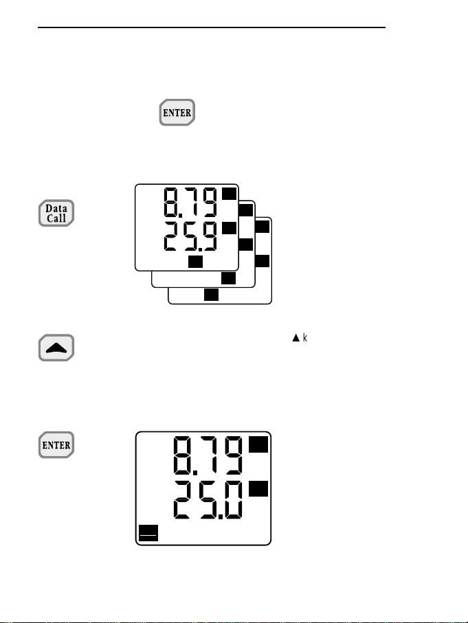
4. Pressing DATA CALL repeatedly gives:
1.
The Maximum value of the probes connected to the inputs
2.
The Minimum value of the
probes connected to the inputs
3.
The Mean value of the probes
connected to the inputs
4.
Returns to normal operating
mode
ENGLISH
125
MED
3
10
°C
MAX
3
10
°C
MIN
3
10
°C
3
10
°C
Page 62

ENGLISH
126
5. Instrument programming.
10
3
=
=
+
++
++
+
=
=
+
=
++
+
=
Returns to normal operating mode, without
storing the changed
values.
Confirms the selected
value and returns to
normal operating
mode
Unloads data from the memory
Returns to normal operating mode
Erases memory (Memory Clear)
Returns to normal operating mode
=
++ +
=
Confirms the selected
value and returns to
normal operating
mode
Sets
Baud Rate
Sets reading or storage interval (from 1 sec. to 12 hours)
Resets relative probes
offset on channel A
Resets relative probes
offset on channel B
3
10
3
10
Page 63

ENGLISH
127
Sets year
00, 01, 02 ... 99
Example: 2000
=
++ +
Sets month
01, 02, 03 ... 12
Example: 01 January
=
++ +
Sets day
01, 02, 03 ... 31
Example: 01
=
++ +
Sets hour
00, 01, 02 ... 23
Example: 00 midnight
=
++ +
Page 64

Enables self cut-out
during storage with an
intervention time equal to
or greater than 1 minute
The instrument does not cut out
automatically during storage
=
++
+
=
Confirms the selected
value and returns to
normal operating mode
+
=
Confirms the selected
value and returns to
normal operating mode
Data printing is complete
Data printing is reduced
=
++
ENGLISH
128
Sets minutes
00, 01, 02 ... 59
Example: 01 minutes
=
++ +
=
Confirms the selected
value and returns to
normal operating
mode, storing the set
date and time
Page 65

ENGLISH
129
=
=
=
++
Returns to normal
operating mode
=
+=
Enters calibration
function
++
6. Activation or disactivation of the serial output.
Serial output active Serial output ended
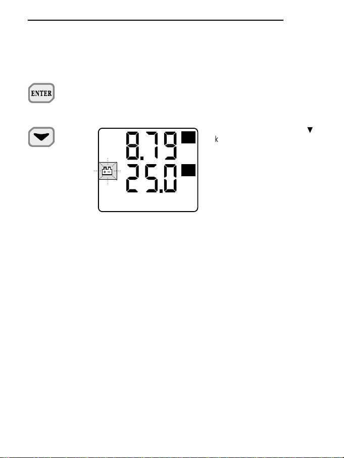
7. Activation or disactivation of the Record function.
When the key is pressed the instrument
gives a beep and starts storing and updating
the MAX, MIN and MEAN value
When the key is held down for more than one second,
the instrument gives a short beep followed by a long one.
The Maximum, Minimum and Mean values have been reset
and the instrument starts updating these values again.
RCD
RCD
RCD
mg/l
°C
Serial
Out
Memory
mg/l
°C
mg/l
°C
Page 66

ENGLISH
130
8. Activation and disactivation of the storage function.
Storage phase active Storage phase ended
Start-Stop
Start-Stop
°C
10
3
Start-Stop
3
10
°C
Serial
Out
Memory
Page 67

INDEX
TECHNICAL DATA. . . . . . . . . . . . . . . . . . . . . . . . . . . . . . . . . . . . . . . . . . . . . . . . . . . . . . . . . . . . 68
INTRODUCTION . . . . . . . . . . . . . . . . . . . . . . . . . . . . . . . . . . . . . . . . . . . . . . . . . . . . . . . . . . . . . 69
KEYBOARD . . . . . . . . . . . . . . . . . . . . . . . . . . . . . . . . . . . . . . . . . . . . . . . . . . . . . . . . . . . . . . . . . 70
PROBE CONNECTION . . . . . . . . . . . . . . . . . . . . . . . . . . . . . . . . . . . . . . . . . . . . . . . . . . . . . . . . 86
HOW TO MEASURE . . . . . . . . . . . . . . . . . . . . . . . . . . . . . . . . . . . . . . . . . . . . . . . . . . . . . . . . . . 86
Attention when using the keyboard. . . . . . . . . . . . . . . . . . . . . . . . . . . . . . . . . . . . . . . . . . . . 87
TEMPERATURE MEASUREMENT . . . . . . . . . . . . . . . . . . . . . . . . . . . . . . . . . . . . . . . . . . . . . . . 88
METHOD OF USING THE INSTRUMENT AND WARNINGS . . . . . . . . . . . . . . . . . . . . . . . . . . . 88
INSTRUMENT SIGNALS AND MALFUNCTIONS . . . . . . . . . . . . . . . . . . . . . . . . . . . . . . . . . . . . 89
LOW BATTERY WARNING AND BATTERY REPLACEMENT . . . . . . . . . . . . . . . . . . . . . . . . . . 90
Faulty operation when switching on after changing the battery . . . . . . . . . . . . . . . . . . . . . . 91
Warning on use of the batteries . . . . . . . . . . . . . . . . . . . . . . . . . . . . . . . . . . . . . . . . . . . . . . 91
STORAGE OF THE INSTRUMENT . . . . . . . . . . . . . . . . . . . . . . . . . . . . . . . . . . . . . . . . . . . . . . . 91
SERIAL INTERFACE RS 232C . . . . . . . . . . . . . . . . . . . . . . . . . . . . . . . . . . . . . . . . . . . . . . . . . . 91
Host commands . . . . . . . . . . . . . . . . . . . . . . . . . . . . . . . . . . . . . . . . . . . . . . . . . . . . . . . . . . 92
DIAGRAM DO 9704 . . . . . . . . . . . . . . . . . . . . . . . . . . . . . . . . . . . . . . . . . . . . . . . . . . . . . . . . . . . 94
EXAMPLE OF A REPORT PRINTED BY THE INSTRUMENT . . . . . . . . . . . . . . . . . . . . . . . . . . 95
INSTRUCTIONS FOR CONNECTING DELTA OHM INSTRUMENTS TO A PC
WITH WINDOWS OPERATIVE SYSTEM . . . . . . . . . . . . . . . . . . . . . . . . . . . . . . . . . . . . . . . . . . 97
Hardware connection . . . . . . . . . . . . . . . . . . . . . . . . . . . . . . . . . . . . . . . . . . . . . . . . . . . . . . 97
Software connection with WINDOWS 3.1. . . . . . . . . . . . . . . . . . . . . . . . . . . . . . . . . . . . . . . 97
Software connection with WINDOWS 95 . . . . . . . . . . . . . . . . . . . . . . . . . . . . . . . . . . . . . . . 103
CALIBRATING THE INSTRUMENT DO 9704 . . . . . . . . . . . . . . . . . . . . . . . . . . . . . . . . . . . . . . . 111
FLOW RATE MEASUREMENTS . . . . . . . . . . . . . . . . . . . . . . . . . . . . . . . . . . . . . . . . . . . . . . . . . 112
CONNECTION OF PROBES TO THE PRESSURE GAUGE DATA LOGGER DO 9704 . . . . . . 113
ENGLISH
131
Page 68

Probe connection diagram . . . . . . . . . . . . . . . . . . . . . . . . . . . . . . . . . . . . . . . . . . . . . . . . . . 113
Classification of pressure measurements. . . . . . . . . . . . . . . . . . . . . . . . . . . . . . . . . . . . . . . 115
Conversion factors and tables . . . . . . . . . . . . . . . . . . . . . . . . . . . . . . . . . . . . . . . . . . . . . . . 116
INSTRUMENT TECHNICAL DATA . . . . . . . . . . . . . . . . . . . . . . . . . . . . . . . . . . . . . . . . . . . . . . . 119
Instrument precision . . . . . . . . . . . . . . . . . . . . . . . . . . . . . . . . . . . . . . . . . . . . . . . . . . . . . . . 119
Probe precision. . . . . . . . . . . . . . . . . . . . . . . . . . . . . . . . . . . . . . . . . . . . . . . . . . . . . . . . . . . 120
ORDER CODES. . . . . . . . . . . . . . . . . . . . . . . . . . . . . . . . . . . . . . . . . . . . . . . . . . . . . . . . . . . . . . 122
GUARANTEE . . . . . . . . . . . . . . . . . . . . . . . . . . . . . . . . . . . . . . . . . . . . . . . . . . . . . . . . . . . . . . . . 123
EXAMPLES OF USE OF THE KEYBOARD. . . . . . . . . . . . . . . . . . . . . . . . . . . . . . . . . . . . . . . . . 124
ENGLISH
132
Page 69

CE CONFORMITY
Safety EN61000-4-2, EN61010-1 level 3
Electrostatic discharge EN61000-4-2 level 3
Electric fast transients EN61000-4-4 level 3
Voltage variations EN61000-4-11
Electromagnetic interference
sucseptibility
IEC1000-4-3
Electromagnetic interference
emission
EN55020 class B
DELTA OHM SRL
VIA G. MARCONI, 5 - 35030 CASELLE DI SELVAZZANO (PD) - ITALY
TEL. 0039-0498977150 r.a. - FAX 0039-049635596
e-mail: deltaohm@tin.it - Web Site: www.deltaohm.com
SIT CALIBRATION
CENTRE N° 124
 Loading...