

Page 1
46-464 MIDI-LATHE STAND EXTENSION
FOR USE WITH DELTA MIDI-LATHES 46-455 AND 46-460 AND LATHE STAND 46-462
IF YOU HAVE ANY QUESTIONS OR COMMENTS ABOUT THIS OR
ANY DELTA MACHINERY ACCESSORY, CALL US TOLL FREE AT
800-223-7278.
SAFETY INSTRUCTIONS
To reduce the risk of injury, read the tool instruction
manual before using any accessory. Failure to heed these warnings
may result in personal injury and serious damage to the tool and
the accessory. When servicing this tool, use only identical replacement parts.
disconnect it from power source before installing and removing
accessories, before adjusting or when making repairs. An
accidental start-up can cause injury.
used with Delta midi-lathes 46-455 and 46-460 and Delta lathe
stand 46-462 and Delta lathe extension bed 46-463.
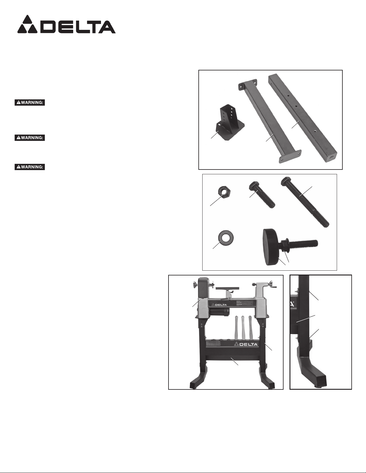
46-464 PARTS (FIG. 1, FIG. 2)
A. Lathe stand platform (1)
B. Extension cross brace (1)
C. Center support leg (1)
D. 3/8-16 x 1-1/2" (38 mm) hex head bolt (2)
E. 3/8-16 x 3-1/2" (89 mm) hex head bolt (5)
F. 3/8-16 nylock nut (7)
G. 3/8 flat washer (14)
H. Leveling foot and jam nut (1)
NOTE: If you are assembling both the 46-462 Lathe Stand and
this 46-464 Lathe Stand Extension at the same time, refer to the
46-462 instruction sheet before proceeding to section Assembly
of Extension with the Stand in this sheet as directed.
To reduce the risk of injury, turn tool off and
To reduce risk of injury this product should only be
A
FIG. 1
F
G
N039890 - JULY09 - REV0
C
B
E
D
H
FIG. 2
ASSEMBLY
DISASSEMBLY OF THE STAND
1. Remove the lathe (I) Fig. 3 from the stand (J).
2. Remove the right side leg (K) Fig. 3 by removing both
sets of bolts, washers and nuts, located at (L) Fig. 4, that
attach leg to cross brace / tool holder (M).
3. Set aside these parts to re-attach later on the very end of
the stand extension.
ASSEMBLY OF EXTENSION WITH THE STAND
NOTE: For ease of alignment, do not fully tighten nuts
until assembly is complete.
1. Bolt center support leg (C) Fig. 5 to cross brace/tool
holder (M) in bottom hole only (shown at (N)) using one
3/8-16 x 3-1/2" (89 mm) hex head bolt (E) Fig. 2, two 3/8
flat washers (G) Fig. 2 and one 3/8-16 nylock nut (F) Fig.
2.
2. Place flat washer on bolt and insert it through center support leg
(C) Fig. 5 and then through the hole (N) in tool holder. Place a
second flat washer on the bolt and fasten with the nylock nut.
3. Make sure jam nut is on rubber leveling foot (H) Fig. 5 (inset)
as shown. Screw in rubber leveling foot (H) as shown in Fig. 5.
Tighten all the way down. Height can be adjusted later.
4. Attach extension brace (B) Figure 6 to center support leg (C) and
cross brace / tool holder (M) in two top holes (P) as shown, using
two 3/8-16 x 3-1/2" (89 mm) hex head bolts (E) Fig. 2, four 3/8
FIG. 3
L
I
M
L
K
J
FIG. 4
flat washers (G) Fig. 2 and two 3/8-16 nylock nuts (F) Fig. 2.
5. For each hole (P) Fig. 6, place washer on bolt and insert the bolt
through hole in extension brace (B), then through hole in center
support leg (C) and then through the cross brace / tool holder (M).
Place a second flat washer on the bolt and fasten with nylock nut.
NOTE: Figure 6 is shown from back of lathe stand.
NOTE: An additional Lathe Stand Extension can be attached in a
similar manner using steps above. Do not attach more than two
Lathe Stand Extensions.
Page 2
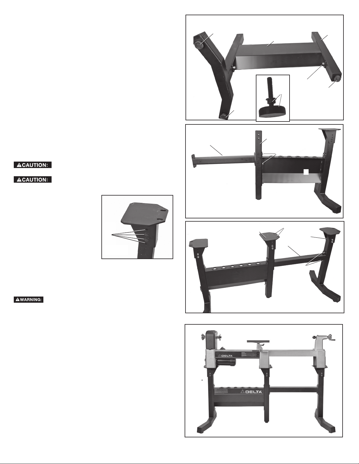
6. Attach right side leg assembly (K) Fig. 7 to the right side of
extension brace (B) in two holes (Q) as shown using two 3/8-16 x
3-1/2" (89 mm) hex head bolts (E) Fig. 2, four 3/8 flat washers (G)
Fig. 2 and two 3/8-16 nylock nuts (F) Fig. 2. Remember to orient
leg as shown in Fig. 7.
7. Attach lathe stand platform (A) Fig. 7 to center support leg using
two 3/8-16 x 3-1/2" (89 mm) hex head bolts (E) Fig. 2, four 3/8 flat
washers (G) Fig. 2 and two 3/8-16 nylock nuts (F) Fig. 2.
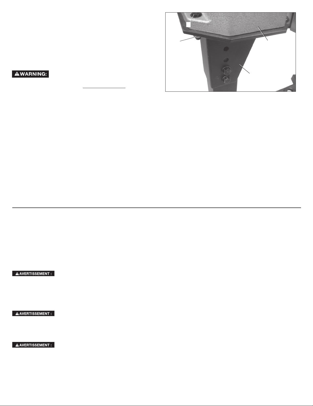
NOTE: The stand height is adjustable by placing two bolts through
two of the four holes (R) Fig. 8 in the lathe stand platform. Be sure
the lathe mounting holes (S) Fig. 7 in top of the platform are facing to
outside, away from tool holder as shown.
8. To attach lathe stand platform (S), place 3/8 flat washers on two
bolts and insert bolts through desired two holes (R) Fig. 8. Place
3/8 flat washers on the bolts after insertion and then tighten with
3/8-16 nylock nuts.
NOTE: Be sure each lathe stand platform is set at the same height.
NOTE: Do not tighten completely.
9. Attach extension bed to your lathe. Refer to the instruction sheet
with your DELTA 46-463 Midi-Lathe Extension Bed for attaching
the bed to your lathe. Lift lathe and extension bed onto lathe
stand platforms as shown in Fig. 9.
Risk of unsafe operation. Make sure hardware on
lathe and lathe extension bed is tight.
Risk of unsafe operation. Use two people when
lifting the lathe and lathe bed extensions.
10. Match up holes in lathe
base with holes in platform.
Attach lathe to stand at these
holes using four 3/8-16 x 1-1/2"
(38 mm) hex head bolts (B)
Figure 10, eight 3/8 flat washers
and four 3/8-16 nylock nuts (A).
11. For each hole, place a washer
on the hex head bolt and insert
it down through the hole at (B)
R
FIG. 8
Fig. 10. Place a second washer
on bolt underneath and tighten
securely using nylock nut.
12. Tighten all lathe stand hardware firmly at this point.
13. Adjust all leveling feet so the lathe stand rests securely on the
floor without rocking or tilting. Then tighten all four jam nuts.
Refer to the instruction sheet with your DELTA 46-463
Midi-Lathe Extension Bed for all relevant safety rules when using the
lathe with the extension.
FIG. 5
FIG. 6
H
M
N
H
H
C
B
P
M
A
S
K
B
Q
C
H
FIG. 7
TROUBLESHOOTING
For assistance w i t h your machine, visit o u r w e b s i t e
at www.deltaportercable.com for a list of service centers or call the
DELTA Machinery help line at 1-800-223-7278 (In Canada call 1-800-
463-3582).
SERVICE
REPLACEMENT PARTS
Use only identical replacement parts. For a parts list or to order parts,
visit our website at www.deltaportercableservicenet.com. You can
also order parts from your nearest factory-owned branch, Authorized
Warranty Service Center or by calling End User Services at (800) 2237278 to receive personalized support from one of our highly-trained
representatives.
SERVICE AND REPAIRS
All quality tools will eventually require servicing and/or replacement
of parts. For information about DELTA Machinery, its factory-owned
branches, or to locate an Authorized Warranty Service Center, visit
our website at www.deltaportercable.com or call our End User
Services at (800) 223-7278. All repairs made by our service centers
FIG. 9
2
Page 3
are fully guaranteed against defective material and workmanship. We
cannot guarantee repairs made or attempted by others. By calling
this number you can also find answers to most frequently asked
questions 24 hours/day.
You can also write to us for information at DELTA Machinery, PO
Box 2468, Jackson, Tennessee 38302-2468 - Attention: End User
Services. Be sure to include all of the information shown on the
nameplate of your tool (model number, type, serial number, date
code, etc.)
ACCESSORIES
Since accessories other than those offered
by DELTA have not been tested with this product, use of such
accessories could be hazardous. For safest operation, only DELTA
recommended accessories should be used with this product.
A complete line of accessories is available from your DELTA Supplier,
DELTA Factory Service Centers, and DELTA Authorized Service
Stations. Please visit our Web Site www.deltaportercable.com for a
catalog or for the name of your nearest supplier.
WARRANTY
To register your tool for warranty service visit our website at www.
deltaportercable.com.
FIVE YEAR LIMITED NEW PRODUCT WARRANTY
DELTA will repair or replace, at its expense and at its option, any
new DELTA machine, machine part, or machine accessory which in
normal use has proven to be defective in workmanship or material,
provided that the customer returns the product prepaid to a DELTA
factory service center or authorized service station with proof of
purchase of the product within five years and provides DELTA with
reasonable opportunity to verify the alleged defect by inspection.
For all refurbished DELTA product, the warranty period is 180 days.
DELTA will not be responsible for any asserted defect which has
resulted from normal wear, misuse, abuse or repair or alteration
made or specifically authorized by anyone other than an authorized
B
A
F
FIG. 10
DELTA service facility or representative. Under no circumstances will
DELTA be liable for incidental or consequential damages resulting
from defective products. Some states do not allow the exclusion
or limitation of incidental or consequential damages, so the above
limitation or exclusion may not apply to you. This warranty is DELTA’s
sole warranty and sets forth the customer’s exclusive remedy,
with respect to defective products; all other warranties, express or
implied, whether of merchantability, fitness for purpose, or otherwise,
are expressly disclaimed by DELTA. For further detail of warranty
coverage and warranty repair information, visit www.deltaportercable.
com or call (888) 848-5175. This warranty gives you specific legal
rights and you may have other rights which vary in certain states or
provinces.
LATIN AMERICA: This warranty does not apply to products sold in
Latin America. For products sold in Latin America, see country specific warranty information contained in the packaging, call the local
company or see website for warranty information.
P
RALLONGE DE BANC DE
TOUR À BOIS MOYEN 46-464
À UTILISER AVEC LES TOURS À BOIS MOYENS DELTA, MODÈ-
LES 46-455 ET 46-460, ET LE BANC DE TOUR À BOIS 46-462
POUR TOUTE QUESTION RELATIVE À CET ACCESSOIRE OU
TOUT AUTRE ACCESSOIRE DELTA, COMPOSER GRATUITEMENT
LE : 800-223-7278.
CONSIGNES DE SÉCURITÉ
Pour réduire tout risque de dommages
corporels, lire le manuel de l’utilisateur respectif à l’outil
avant l’utilisation de tout accessoire. Tout manquement à ces
avertissements augmente les risques de blessures, et les risques
de sérieusement endommager l’appareil et ses accessoires. Lors
de l’entretien de cet outil, n’utiliser que des pièces de rechange
identiques.
corporels, arrêter et débrancher l’outil du secteur avant d’installer
ou retirer tout accessoire, avant tout réglage ou pour faire toute
réparation. Tout démarrage accidentel comporte des risques de
dommages corporels.
corporels, ce produit ne devrait être utilisé qu’avec les tours à
bois moyens Delta, modèles 46-455 et 46-460, les bancs de tour
Delta 46-462 et les extensions de banc de tour Delta 46-463.
PIÈCES DE LA 46-464 (Fig. 1, Fig. 2)
A. Plateforme du banc de tour à bois (1)
B. Barre transversale de rallonge (1)
C. Pied de support central (1)
Pour réduire tout risque de dommages
Pour réduire tout risque de dommages
D. Boulons à tête hexagonale de 38 mm (3/8-16 x 1-1/2 po), (2)
E. Boulons à tête hexagonale de 89 mm (3/8-16 x 3-1/2 po), (5)
F. Écrous nylock 3/8-16 (7)
G. Rondelles plates de 3/8 (14)
H. Pied réglable avec contre-écrou (1)
REMARQUE : Si vous effectuez en même temps, l’installation
du banc de tour 46-462 et celle de la rallonge de banc de tour
46-464, reportez-vous aux directives d’utilisation du 46-462 avant
de passer à la section Montage de la rallonge au banc de tour de
ces directives.
MONTAGE
DÉMONTAGE DU BANC
1. Retirez le tour (I), fig. 3, du banc (J).
2. Retirez le pied droit (K), fig. 3, en retirant les deux jeux de boulons,
rondelles et écrous, situés sur (L), fig. 4, et qui rattachent le pied à
la barre transversale/porte-outils (M).
3. Mettez l’ensemble de ces pièces de côté pour les rattacher plus
tard, à l’extrémité de la rallonge de banc.
MONTAGE DE LA RALLONGE AU BANC
REMARQUE : Pour faciliter l’alignement, ne pas resserrer
complètement les écrous tant que le montage n’est pas terminé.
1. Arrimez le pied de support central (C), fig. 5, à la barre
transversale/porte-outils (M) par le trou inférieur seulement (illustré
par N), à l’aide d’un boulon à tête hexagonale de 89 mm (3/816 x 3-1/2 po) (E), fig 2, deux rondelles plates de 3/8 (G), fig. 2, et
un écrou nylock de 3/8-16 (F), fig. 2.
2. Placez une rondelle sur un boulon puis insérez-le dans le pied de
support central (C), fig. 5, puis dans le trou (N) du porte-outils.
Insérez une deuxième rondelle plate sur le boulon puis resserrez
avec un écrou nylock.
3
Page 4

3. Assurez-vous que le contre-écrou est bien inséré sur le pied
de réglage en caoutchouc (H), fig. 5 (encadré), comme illustré.
Vissez le pied réglable en caoutchouc (H), comme illustré en fig.
5. Resserrez à fond. La hauteur pourra être ajustée plus tard.
4. Rattachez la barre transversale de rallonge (B), fig. 6, au pied de
support central (C) et à la barre transversale/porte-outils (M) par
les deux trous supérieurs (P), comme illustré, à l’aide de deux
boulons à tête hexagonale de 89 mm (3/8-16 x 3-1/2 po) (E), fig.
2, quatre rondelles plates de 3/8 (G), fig. 2, et deux écrous nylock
de 3/8-16 (F), fig. 2.
5. Pour chacun des trous (P), fig. 6, placez une rondelle sur un
boulon puis insérez-le dans le trou de la barre transversale de
rallonge (B) puis dans le trou du pied de support central (C) et
enfin dans la barre transversale/porte-outils (O). Insérez une
deuxième rondelle plate sur le boulon puis resserrez avec un
écrou nylock.
REMARQUE : La figure 6 montre l’arrière du banc de tour.
REMARQUE : Une rallonge de banc de tour supplémentaire peut
être rattachée de la même manière en suivant la procédure ci-dessus.
Ne pas rattacher plus de deux rallonges de banc de tour.
6. Rattachez le dispositif du pied droit (K), fig. 7 sur l’extrémité droite
de la barre transversale de rallonge (B) par deux trous (Q), comme
illustré, à l’aide de deux boulons à tête hexagonale de 89 mm
(3/8-16 x 3-1/2 po) (E), fig. 2, quatre rondelles plates de 3/8 (G),
fig. 2, et deux écrous nylock de 3/8-16 (F), fig. 2. N’oubliez pas
de bien orienter le pied comme illustré.
7. Rattachez la plateforme (A) du banc de tour, fig. 7, au pied de
support central à l’aide de deux boulons à tête hexagonale de
89 mm (3/8-16 x 3-1/2 po) (E), fig. 2, quatre rondelles plates de
3/8 (G), fig. 2, et deux écrous nylock de 3/8-16 (F), fig. 2.
REMARQUE : On peut régler la hauteur du banc en plaçant deux
boulons au travers de deux des quatre trous (R), fig. 8, sur la
plateforme du banc de tour. S’assurer que les trous d’installation du
tour (S), fig. 7, sur la plateforme sont orientés vers l’extérieur, et non
pas vers le porte-outils, comme illustré.
8. Pour le rattacher, placez deux rondelles plates de 3/8 sur deux
boulons, puis insérez les boulons dans les trous (R) désirés, fig. 8.
Placez des rondelles plates de 3/8 sur les boulons après insertion
puis resserrez avec des écrous nylock de 3/8-16.
REMARQUE : S’assurer que toutes les plateformes du banc de tour
sont bien à la même hauteur.
REMARQUE : Ne pas encore serrer complètement.
9. Rattachez l’extension de banc au tour. Reportez-vous aux
directives d’utilisation incluses avec l’Extension de banc de tour à
bois moyen DELTA 46-463 pour rattacher le tour au banc. Placez
le tour et l’extension de banc sur les plateformes du banc de tour,
comme illustré en figure 9.
Conditions d’utilisation dangereuses.
S’assurer que les fixations sur le tour et l’extension de banc de
tour sont soigneusement serrées.
Conditions d’utilisation dangereuses.
Soulever le tour et les extensions de banc de tour à deux
personnes.
10. Alignez les trous sur la base du tour avec les trous de la plateforme.
Rattachez le tour au banc par ces trous à l’aide de quatre boulons
à tête hexagonale de 38 mm (3/8-16 x 1-1/2 po) (B), fig. 10, huit
rondelles plates de 3/8 et quatre écrous nylock de 3/8-16 (A).
11. Pour chacun des trous, placez une rondelle sur les boulons à tête
hexagonale puis insérez ces derniers dans les trous (B), fig. 10.
Placez une deuxième rondelle dessous, sur chaque boulon, puis
resserrez soigneusement à l’aide d’un écrou nylock.
12. Resserrez alors fermement toutes les fixations sur le banc de
tour.
13. Ajustez tous les pieds réglables de façon à ce que le banc de tour
s’appuie en toute sécurité, fermement et à plat, sur le sol. Puis
resserrez les quatre contre-écrous.
avec l’Extension de banc de tour à bois moyen DELTA 46-463 pour
toute consigne de sécurité pertinente à l’utilisation du tour avec une
extension.
Se reporter aux directives d’utilisation incluses
DEPANNAGE
Pour l'assistance avec votre outil, visiter notre site web à
www.deltaportercable.com pour une liste de centres de maintenance
ou appeler la ligne d'aide de DELTA Machinery à 1-800-223-7278.
(Canada: 1-800-463-3582).
SERVICE
PIÈCES DE RECHANGE
Utiliser seulement des pièces de rechange identiques. Pour obtenir
une liste des pièces de rechange ou pour en commander, consulter
notre site Web au www.deltaportercableservicenet.com. Il est
aussi possible de commander des pièces auprès d’une succursale
d’usine ou un centre de réparation sous garantie autorisé ou en
communiquant avec le service à la clientèle au 800-223-7278 pour
recevoir un soutien personnalisé de l’un de nos représentants bien
formés.
ENTRETIEN ET RÉPARATION
Tous les outils de qualité finissent par demander un entretien ou un
changement de pièce. Pour de plus amples renseignements à propos
de DELTA Machinery, ses succursales d’usine ou pour trouver un
centre de réparation sous garantie autorisé, consulter notre site Web
au www.deltaportercable.com ou communiquer avec notre service
à la clientèle au 800-223-7278. Toutes les réparations effectuées
dans nos centres de réparation sont entièrement garanties contre les
défauts de matériaux et de main-d’œuvre. Nous ne pouvons garantir
les réparations effectuées en partie ou totalement par d’autres.
En composant ce numéro à toute heure du jour ou de la nuit, il est
également possible de trouver les réponses aux questions les plus
courantes.
Pour de plus amples renseignements, écrire également à DELTA
Machinery, PO Box 2468, Jackson, Tennessee 38302-2468, É.-U. à l’attention de : End User Services. S’assurer d’indiquer toutes les
informations figurant sur la plaque signalétique de l’outil (numéro du
modèle, type, numéro de série, code de date, etc.).
ACCESSOIRIES
offertspar DELTA n'ont pas été testés avec ce produit, utilisation
de tels accessoires a pu être dangereux. Pour l'exploitation
sûre, seulement DELTA a recommandé des accessoires devrait
être utilisé avec ce produit.
Une ligne complète des accessoires est fournie des centres
commerciaux d'usine de par votre de DELTA fournisseur, de DELTA,
et des stations service autorisées. Veuillez visiter notre site Web
www.deltaportercable.com pour un catalogue ou pour le nom de
votre fournisseur plus proche.
Depuis des accessoires autre que ceux
GARANTIE
Pour enregistrer votre outil pour la garantie service la visite notre site
Web à www.deltaportercable.com.
GARANTIE LIMITÉE DE CINQ ANS
DELTA réparera ou remplacera, à ses frais et à sa discrétion, toute
nouvelle machine DELTA, pièce de rechange ou tout accessoire
qui, dans des circonstances d'utilisation normale, s'est avéré
défectueux en raison de défauts de matériau ou de fabrication,
à condition que le client retourne le produit (transport payé
d'avance) au centre de réparation de l'usine DELTA ou à un centre
de réparation autorisé accompagné d'une preuve d'achat et dans
les cinq ans de la date d'achat du produit, et fournisse à DELTA
une opportunité raisonnable de vérifier le défaut présumé par une
inspection. La période de garantie des produits DELTA réusinés
est de 180 jours. DELTA ne peut être tenu pour responsable des
défauts résultants de l'usure normale, de la mauvaise utilisation,
4
Page 5

de l'abus, de la réparation ou de la modification du produit, sauf
en cas d'autorisation spécifique d'un centre de réparation ou
d'un représentant DELTA autorisé. En aucune circonstance DELTA
ne peut être tenu pour responsable des dommages accidentels
ou indirects résultant d'un produit défectueux. Certains États
ou provinces ne permettent pas l’exclusion ou la restriction de
dommages accessoires ou indirects, auquel cas, les exclusions
ou limitations ci-dessus pourraient ne pas être applicables. Cette
garantie constitue la seule garantie de DELTA et le recours exclusif
des clients en ce qui concerne les produits défectueux ; toutes les
autres garanties, expresses ou implicites, de qualité marchande,
d'adéquation à un usage particulier, ou autre, sont expressément
déclinées par DELTA. Pour obtenir de plus amples renseignements
sur les pièces ou les réparations couvertes par la présente garantie,
visiter le site www.deltaportercable.com ou composer le (888)
848-5175. Cette garantie confère des droits légaux particuliers à
l’acheteur, mais celui-ci pourrait aussi bénéficier d’autres droits
variant d’un état ou d’une province à l’autre.
AMÉRIQUE LATINE : Cette garantie ne s’applique aux produits
vendus en Amérique latine. Pour ceux-ci, veuillez consulter les
informations relatives à la garantie spécifique présente dans
l’emballage, appeler l’entreprise locale ou consulter le site Web pour
les informations relatives à cette garantie.
EXTENSIÓN 46-464 DEL
SOPORTE PARA TORNOS
MEDIANOS
COMPATIBLE CON TORNOS MEDIANOS 46-455 Y 46-460 Y CON
EL SOPORTE PARA TORNOS 46-462 MARCA DELTA
SI TIENE ALGUNA PREGUNTA ACERCA DE ESTE O CUALQUIER
OTRO ACCESORIO PARA MAQUINARIAS DELTA, LLÁMENOS
GRATUITAMENTE AL 800-223-7278.
INSTRUCCIONES DE SEGURIDAD
Para reducir el riesgo de lesiones, lea el manual
de instrucciones de la herramienta antes de usar cualquiera de los
accesorios. De no seguir estas advertencias podrían producirse
lesiones corporales y graves daños a la herramienta y al accesorio.
Cuando realice el mantenimiento de esta herramienta, utilice
únicamente repuestos idénticos.
herramienta y desenchúfela antes de instalar y quitar accesorios,
y antes de realizar ajustes o reparaciones. Un arranque accidental
puede causar lesiones.
producto sólo debe utilizarse con los tornos medianos 46-455 y
46-460 marca Delta, con el soporte 46-462 marca Delta para tornos,
y con el asiento de la extensión 46-463 marca Delta para tornos.
PIEZAS DEL 46-464 (FIG. 1, FIG. 2)
A. Plataforma del soporte para tornos (1)
B. Soporte transversal de la extensión (1)
C. Base de apoyo central (1)
D. Pernos hexagonales de 38 mm (3/8-16 x 1-1/2 pulg.) (2)
E. Pernos hexagonales de 89 mm (3/8-16 x 3-1/2 pulg.) (5)
F. Tuercas de seguridad Nylock de 3/8-16 (7)
G. Arandelas planas de 3/8 (14)
H. Pata niveladora con tuerca de bloqueo (1)
NOTA: Si está ensamblando el soporte para tornos 46-462
y la extensión 46-464 del soporte para tornos al mismo
tiempo, remítase a la hoja de instrucciones del 46-462 antes
de remitirse a la sección Ensamblaje de la extensión con el
soporte que aparece en esta hoja, según se indique.
ENSAMBLAJE
DESMONTAJE DEL SOPORTE
1. Retire el torno (I) Fig. 3 del soporte (J).
2. Quite ambos juegos de pernos, arandelas y tuercas de (L) Fig.
4 que fijan la base derecha (K) Fig. 3 al soporte transversal /
sujeta herramientas (M).
Para reducir el riesgo de lesiones, apague la
Para reducir el riesgo de lesiones, este
3. Ponga a un lado estas piezas para volverlas a instalar una
vez que la extensión del soporte esté casi completamente
instalada.
ENSAMBLAJE DE LA EXTENSIÓN CON EL SOPORTE
NOTA: Con el fin de facilitar el alineamiento, no ajuste
completamente los pernos y las tuercas hasta no finalizar el
ensamblaje.
1. Fije la base de apoyo central (C) Fig. 5 al soporte transversal
/ sujeta herramientas (M) con un perno hexagonal de 89 mm
(3/8-16 x 3-1/2 pulg.) (E) Fig. 2, dos arandelas planas de 3/8
(G) Fig. 2 y una tuerca de seguridad Nylock de 3/8-16 (F) Fig. 2
instalados sólo en el orificio inferior (que aparece en (N)).
2. Coloque una arandela plana en el perno e insértelo en la base
de apoyo central (C) Fig. 5 y luego en el orificio (N) del sujeta
herramientas. Coloque una segunda arandela plana en el
vástago del perno y termine de fijarlo con la tuerca de seguridad
Nylock.
3. Verifique que la pata niveladora de goma (H) Fig. 5 (recuadro)
tenga una tuerca de bloqueo como aparece en la imagen.
Atornille la pata niveladora de goma (H) como lo muestra la
Fig. 5. Enrósquela completamente hasta abajo. Podrá ajustar la
altura después.
4. Utilice dos pernos hexagonales de 89 mm (3/8-16 x 3-1/2
pulg.) (E) Fig. 2, cuatro arandelas planas de 3/8 (G) Fig. 2 y dos
tuercas de seguridad Nylock de 3/8-16 (F) Fig. 2 para fijar el
soporte de la extensión (B) Figura 6 a la base de apoyo central
(C) y al soporte transversal / sujeta herramientas (M) por los dos
orificios superiores (P) como aparece.
5. Coloque una arandela en cada uno de los pernos hexagonales
e insértelos en los orificios correspondientes (P) Fig. 6 del
soporte de la extensión (B), luego por el orificio de la base de
apoyo central (C) y luego por el soporte transversal / sujeta
herramientas (O). Coloque una segunda arandela plana en el
vástago del perno y termine de fijarlo con la tuerca de seguridad
Nylock.
NOTA: La Figura 6 muestra la parte posterior del soporte para
tornos.
NOTA: Si desea instalar una extensión adicional en el soporte
para tornos, siga los pasos anteriores. No instale más de dos
extensiones al soporte para tornos.
6. Utilice dos pernos hexagonales de 89 mm (3/8-16 x 3-1/2
pulg.)(E) Fig. 2, cuatro arandelas planas de 3/8 (G) Fig. 2 y
dos tuercas de seguridad Nylock de 3/8-16 (F) Fig. 2 para fijar
la base derecha (K) Fig. 7 al lado derecho del soporte de la
extensión (B) usando los dos orificios (Q) como aparece en la
imagen. Recuerde orientar la base como aparece en la imagen.
7. Utilice dos pernos hexagonales de 89 mm (3/8-16 x 3-1/2
pulg.) (E) Fig. 2, cuatro arandelas planas de 3/8 (G) Fig. 2 y dos
tuercas de seguridad Nylock de 3/8-16 (F) Fig. 2 para fijar la
plataforma del soporte para tornos (A) Fig. 7 a la base de apoyo
central.
5
Page 6

NOTA: Para ajustar la altura del soporte, inserte dos pernos
hexagonales en dos de los cuatro orificios (R) Fig. 8 de la
plataforma del soporte para tornos. Verifique que los orificios
de montaje del torno (S) Fig. 7 que está encima de la plataforma
queden orientados hacia afuera, en dirección opuesta al sujeta
herramientas, como aparece en la imagen.
8. Para fijarlo, coloque dos pernos, cada uno con una arandela
plana de 3/8, en los dos orificios deseados (R) Fig. 8. Coloque
otra arandela plana de 3/8 en el vástago de cada perno y
termine de fijarlo con tuercas de seguridad Nylock de 3/8-16.
NOTA: Verifique que ambas plataformas del soporte para tornos
estén a la misma altura.
NOTA: No ajuste completamente.
9. Fije el asiento de la extensión a su torno. Remítase a la hoja
de instrucciones que vino con su Asiento de extensión DELTA
46-463 para tornos medianos para ver cómo fijar el asiento a su
torno. Levante el torno y el asiento de la extensión y colóquelos
sobre las plataformas del soporte para tornos como aparece en
la Fig. 9.
Riesgo de peligro durante su operación.
Verifique que los accesorios de montaje del torno y del asiento
de la extensión para tornos estén bien ajustados.
Riesgo de peligro durante su operación. Se
requieren dos personas para levantar el torno y los asientos de
la extensión para tornos.
10. Alinee los orificios de la base del torno con los de la plataforma.
Fije el torno al soporte con cuatro pernos hexagonales de 38 mm
(3/8-16 x 1-1/2 pulg.) (B) Figura 10, ocho arandelas planas de
3/8 y cuatro tuercas de seguridad Nylock de 3/8-16 (A) en estos
orificios.
11. Coloque una arandela en cada uno de los pernos hexagonales e
insértelos en los orificios correspondientes (B) Fig. 10. Coloque
una segunda arandela en el vástago de cada uno de los pernos
y termine de fijarlos con las tuercas de seguridad Nylock.
12. Ajuste bien todos los accesorios de montaje del soporte para
tornos.
13. Ajuste las patas niveladoras de modo que el soporte para
tornos quede estable sobre el suelo, sin mecerse o inclinarse.
Luego, termine de ajustar las cuatro tuercas de bloqueo.
Cuando utilice el torno con la extensión,
remítase a la hoja de instrucciones que vino con su Asiento de
extensión DELTA 46-463 para tornos medianos para ver todas las
reglas de seguridad relevantes.
LOCALIZACION DE FALLAS
Para obtener asistencia para su máquina, visite nuestro sitio Web en
www.deltaportercable.com para tener acceso a una lista de centros
de servicio o llame a la línea de ayuda de DELTA Machinery al 1-800223-7278. (En Canadá, llame al 1-800-463-3582.)
SERVICIO
PIEZAS DE REPUESTO
Utilice sólo piezas de repuesto idénticas. Para obtener una lista
de las piezas o para solicitarlas, visite nuestro sitio Web en www.
deltaportercableservicenet.com. También puede solicitar piezas
en una de nuestras sucursales o centros de mantenimiento con
garantía autorizados más cercanos, o llamando a End User Services
(Servicios para el usuario final) al (800) 223-7278 para obtener
asistencia personalizada de uno de nuestros representantes
altamente capacitados.
MANTENIMIENTO Y REPARACIONES
Con el paso del tiempo, todas las herramientas de calidad requieren
mantenimiento o reemplazo de las piezas. Para obtener información
acerca de DELTA Machinery y sus sucursales o para localizar un
centro de mantenimiento con garantía autorizado, visite nuestro
sitio Web en www.deltaportercable.com o llame a End User
Services (Servicios para el usuario final) al (800) 223-7278. Todas
las reparaciones realizadas en nuestros centros de mantenimiento
están completamente garantizadas en relación con los materiales
defectuosos y la mano de obra. No podemos otorgar garantías en
relación con las reparaciones ni los intentos de reparación de otras
personas. Si llama a este número, también encontrará las respuestas
a las preguntas más frecuentes durante las 24 horas del día.
Asimismo, para obtener información puede escribirnos a DELTA
Machinery, PO Box 2468, Jackson, Tennessee 38302-2468 Attention: End User Services. Asegúrese de incluir toda la información
mencionada en la placa de la herramienta (número de modelo, tipo,
número de serie, código de fecha, etc.)
ACCESORIOS
Puesto que los accesorios con excepción
de ésos ofrecidos por DELTA no se han probado con este
producto, el uso de tales accesorios podría ser peligroso. Para
la operación más segura, solamente el DELTA recomendó los
accesorios se debe utilizar con este producto
Una línea completa de accesorios está disponible de su surtidor
de DELTA, centros de servicio de la fábrica de DELTA, y estaciones
autorizadas delta. Visite por favor nuestro Web site www.
deltaportercable.com para un catálogo o para el nombre de su
surtidor más cercano.
PÓLIZA DE GARANTÍA
IDENTIFICACIÓN DELPRODUCTO:
Sello o firma del Distribuidor.Nombre del producto: ___________
Mod./Cat.: Marca: Núm. de serie: (Datos
para ser llenados por el distribuidor) Fecha de compra y/o
entrega del producto: Nombre y domicilio del
distribuidor donde se adquirió el producto:____________________
Este producto está garantizado por tres años de garantía limitada a partir
de la fecha de entrega, contra cualquier defecto en su funcionamiento,
así como en materiales y mano de obra empleados para su fabricación.
Nuestra garantía incluye la reparación o reposición del producto y/o
componentes sin cargo alguno para el cliente, incluyendo mano de
obra, así como los gastos de transportación razonablemente erogados
derivados del cumplimiento de este certificado. Para hacer efectiva esta
garantía deberá presentar su herramienta y esta póliza sellada por el
establecimiento comercial donde se adquirió el producto, de no contar
con ésta, bastará la factura de compra.
EXCEPCIONES
Esta garantía no será válida en los siguientes casos:
•Cuando elproductosehubieseutilizadoencondicionesdistintasa
las normales;
•Cuando el producto no hubiese sido operado de acuerdo con el
instructivo de uso que se acompaña;
•Cuandoelproductohubiesesidoalteradooreparadoporpersonas
distintas a las enlistadas al final de este certificado.
Anexo encontrará una relación de sucursales de servicio de fábrica,
centros de servicio autorizados y franquiciados en la República
Mexicana, donde podrá hacer efectiva su garantía yadquirir partes,
refacciones y accesorios originales.
6
Page 7

PARA REPARACIÓN Y SERVICIO DE SUS
HERRAMIENTAS ELÉCTRICAS, FAVOR DE DIRIGIRSE
AL CENTRO DE SERVICIO MÁS CERCANO
CULIACAN, SIN
Blvd.Emiliano Zapata 5400-1 Poniente
Col. San Rafael (667) 717 89 99
GUADALAJARA, JAL
Av. La Paz #1779 - Col. Americana Sector Juárez (33) 3825 6978
MEXICO, D.F.
Eje Central Lázaro Cárdenas No. 18
Local D, Col. Obrera (55) 5588 9377
MERIDA, YUC
Calle 63 #459-A - Col. Centro (999) 928 5038
MONTERREY, N.L.
Av. Francisco I. Madero 831 Poniente - Col. Centro (818) 375 23 13
PUEBLA, PUE
17 Norte #205 - Col. Centro (222) 246 3714
QUERETARO, QRO
Av. San Roque 274 - Col. San Gregorio (442) 2 17 63 14
SAN LUIS POTOSI, SLP
Av. Universidad 1525 - Col. San Luis (444) 814 2383
TORREON, COAH
Blvd. Independencia, 96 Pte. - Col. Centro (871) 716 5265
VERACRUZ, VER
Prolongación Díaz Mirón #4280 - Col. Remes (229) 921 7016
VILLAHERMOSA, TAB
Constitución 516-A - Col. Centro (993) 312 5111
PARA OTRAS LOCALIDADES:
Si se encuentra en México, por favor llame al (55) 5326 7100
Si se encuentra en U.S., por favor llame al
(800) 223-7278
GARANTIA
Para registrar la herramienta para obtener el mantenimiento cubierto
por la garantía de la herramienta, visite nuestro sitio web en www.
deltaportercable.com.
GARANTÍA LIMITADA DE CINCO AÑOS PARA PRODUCTOS NUEVOS
DELTA reparará o reemplazará, a expensas y opción propias, cualquier
máquina nueva, pieza de máquina nueva o accesorio de máquina
nuevo DELTA que durante el uso normal haya presentado defectos de
fabricación o de material, siempre que el cliente devuelva el producto con
el transporte prepagado a un centro de servicio de fábrica DELTA o una
estación de servicio autorizado DELTA, con un comprobante de compra
del producto, dentro del plazo de cinco años y dé a DELTA una oportunidad
razonable de verificar el supuesto defecto mediante la realización de
una inspección. Para todos los productos DELTA reacondicionados, el
período de garantía es de 180 días. DELTA no será responsable de ningún
defecto alegado que haya resultado del desgaste normal, uso indebido,
abuso o reparación o alteración realizada o autorizada específicamente
por alguien que no sea un centro de servicio autorizado DELTA o un
representante autorizado DELTA. DELTA no será responsable en ninguna
circunstancia de los daños incidentales o emergentes que se produzcan
como resultado de productos defectuosos. Algunos estados no permiten
la exclusión o limitación de los daños incidentales o resultantes, por lo
que la limitación o exclusión anterior puede no aplicarse a usted. Esta
garantía es la única garantía de DELTA y establece el recurso exclusivo del
cliente en lo que respecta a los productos defectuosos; DELTA rechaza
expresamente todas las demás garantías, expresas o implícitas, tanto
de comerciabilidad como de idoneidad para un propósito o de cualquier
otro tipo. Para mayores detalles sobre la cobertura de la garantía e
información acerca de reparaciones realizadas bajo garantía, visítenos en
www.deltaportercable.com o dirígase al centro de servicio más cercano
(888) 848-5175. Esta garantía no aplica a accesorios o a daños causados
por reparaciones realizadas o intentadas por terceros. Esta garantía le
otorga derechos legales específicos, además de los cuales puede tener
otros dependiendo del estado o provincia en que se encuentre.
AMÉRICA LATINA: Esta garantía no se aplica a los productos que
se venden en América Latina. Para los productosque se venden
en América Latina, debe consultar la información de la garantía
específica del país que viene en el empaque, llamar a la compañía
local o visitar el sitio Web a fin de obtener esa información.
SOLAMENTE PARA PROPÓSITO DE MÉXICO:
IMPORTADO POR: DELTA S.A. DE C.V.
BOSQUES DE CIDROS, ACCESO RADIATAS NO.42
3A. SECCIÓN DE BOSQUES DE LAS LOMAS
DELEGACIÓN CUAJIMALPA,
05120, MÉXICO, D.F.
TEL. (52) 555-326-7100
R.F.C.: BDE810626-1W7
Para servicio y ventas consulte
“HERRAMIENTAS ELECTRICAS”
en la sección amarilla.
7
Page 8

Delta Machinery, PO Box 2468, Jackson, TN 38302-2468 (800) 223-7278 - U.S. (800) 463-3582 - CANADA
www.deltaportercable.com Copyright © 2008 Delta Machinery
 Loading...