

Page 1

MIDILATHE
Tour Midi-Lathe
Torno Midi
Français (37)
Español (72)
Instruction manual
Manuel d’utilisation
Manual de instrucciones
www.DeltaMachinery.com
INSTRUCTIVO DE OPERACIÓN, CENTROS DE SERVICIO
Y PÓLIZA DE GARANTÍA. LÉASE ESTE
INSTRUCTIVO ANTES DE USAR EL PRODUCTO.
46-455
46-460
Page 2

TABLE OF CONTENTS
IMPORTANT SAFETY INSTRUCTIONS .................... 2
SAFETY GUIDELINES - DEFINITIONS .....................2
GENERAL SAFETY RULES .......................................3
ADDITIONAL SPECIFIC SAFETY RULES ...............4
FUNCTIONAL DESCRIPTION ....................................6
CARTON CONTENTS ...............................................6
ASSEMBLY .................................................................7
OPERATION ...............................................................7
TROUBLESHOOTING ................................................ 15
MAINTENANCE .......................................................... 15
SERVICE ..................................................................... 17
ACCESSORIES ..........................................................18
WARRANTY ................................................................18
FRANÇAIS .................................................................. 19
ESPAÑOL ...................................................................36
IMPORTANT SAFETY INSTRUCTIONS
Read all warnings and operating instructions before using any tool or equipment.
When using tools or equipment, basic safety precautions should always be followed to reduce
the risk of personal injury. Improper operation, maintenance or modification of tools or equipment could result in serious
injury and property damage. There are certain applications for which tools and equipment are designed. DELTA® Power Equipment Corporation
strongly recommends that this product NOT be modified and/or used for any application other than for which it was designed.
If you have any questions relative to its application DO NOT use the product until you have written DELTA® Power Equipment Corporation
and we have advised you. Contact us online at
Equipment Corporation, 99 Roush Street, Anderson, South Carolina 29625.
• Power Tool Institute, 1300 Sumner Avenue, Cleveland, OH 44115-2851or online at www.powertoolinstitute.com
• National Safety Council, 1121 Spring Lake Drive, Itasca, IL 60143-3201
• American National Standards Institute, 25 West 43rd Street, 4 oor, New York, NY 10036 www.ansi.org - ANSI 01.1
Safety Requirements for Woodworking Machines
• U.S. Department of Labor regulations www.osha.gov
www.DeltaMachinery.com
or by mail at Technical Service Manager, DELTA® Power
SAVE THESE INSTRUCTIONS!
SAFETY GUIDELINES - DEFINITIONS
It is important for you to read and understand this manual. The information it contains relates to protecting YOUR SAFETY
and PREVENTING PROBLEMS. The symbols below are used to help you recognize this information.
indicates an imminently hazardous situation which, if not avoided, will result in death or serious injury.
indicates a potentially hazardous situation which, if not avoided, could result in death or serious injury.
indicates a potentially haz ard ous situation which, if not avoided, may result in minor or mod er ate injury.
indicates a practice not related to personal injury which, if not avoided, may result in property damage.
Some dust created by power sanding, sawing, grinding, drilling, and other construction activities contains
chemicals known to the State of California to cause cancer, birth defects or other reproductive harm.
Some examples of these chemicals are:
• lead from lead-based paints,
• crystalline silica from bricks and cement and other masonry products, and
• arsenic and chromium from chemically-treated lumber.
Your risk from these exposures varies, depending on how often you do this type of work. To reduce your exposure to these
chemicals: work in a well ventilated area, and work with approved safety equipment, al ways wear NIOSH/OSHA approved,
properly t ting face mask or res pi ra tor when us ing such tools.
2
Page 3

GENERAL SAFETY RULES
Failure to follow these rules may result in serious personal injury.
1. For your own safety, read the instruction manual
before operating the machine. Learning the machine’s
application, limitations, and specic hazards will greatly
minimize the possibility of accidents and injury.
2. Wear eye and hearing protection and always use
safety glasses. Everyday eyeglasses are not safety
glasses. Use certied safety equipment. Eye protection
equipment should comply with ANSI Z87.1 standards.
Hearing equipment should comply with ANSI S3.19
standards.
3. Wear proper apparel. Do not wear loose clothing, gloves,
neckties, rings, bracelets, or other jewelry which may get
caught in moving parts. Nonslip protective footwear is
recommended. Wear protective hair covering to contain
long hair.
4. Do not use the machine in a dangerous environment.
The use of power tools in damp or wet locations or in rain
can cause shock or electrocution. Keep your work area
well-lit to prevent tripping or placing arms, hands, and
ngers in danger.
5. Do not operate electric tools near flammable liquids
or in gaseous or explosive atmospheres. Motors and
switches in these tools may spark and ignite fumes.
6. Maintain all tools and machines in peak condition.
Keep tools sharp and clean for best and safest
performance. Follow instructions for lubricating and
changing accessories. Poorly maintained tools and
machines can further damage the tool or machine and/or
cause injury.
7. Check for damaged parts. Before using the machine,
check for any damaged parts. Check for alignment of
moving parts, binding of moving parts, breakage of parts,
and any other conditions that may affect its operation.
A guard or any other part that is damaged should be
properly repaired or replaced with DELTA® or factory
authorized replacement parts. Damaged parts can cause
further damage to the machine and/or injury.
8. Keep the work area clean. Cluttered areas and benches
invite accidents.
9. Keep children and visitors away. Your shop is a
potentially dangerous environment. Children and visitors
can be injured.
10. Reduce the risk of unintentional starting. Make sure
that the switch is in the “OFF” position before plugging in
the power cord. In the event of a power failure, move the
switch to the “OFF” position. An accidental start-up can
cause injury. Do not touch the plug’s metal prongs when
unplugging or plugging in the cord.
11. Use the guards. Check to see that all safety devices are
in place, secured, and working correctly to prevent injury.
12. Remove adjusting keys and wrenches before starting
the machine. Tools, scrap pieces, and other debris can
be thrown at high speed, causing injury.
13. Use the right machine. Don’t force a machine or an
attachment to do a job for which it was not designed.
Damage to the machine and/or injury may result.
14. Use recommended accessories. The use of accessories
and attachments not recommended by DELTA® may cause
damage to the machine or injury to the user.
15. Use the proper extension cord. Make sure your
extension cord is in good condition. When using an
extension cord, be sure to use one heavy enough to carry
the current your product will draw. An undersized cord will
cause a drop in line voltage, resulting in loss of power and
overheating. See the Extension Cord Chart for the correct
size depending on the cord length and nameplate ampere
rating. If in doubt, use the next heavier gauge. The smaller
the gauge number, the heavier the cord.
16. Secure the workpiece. Use clamps or a vise to hold the
workpiece when practical. Loss of control of a workpiece
can cause injury.
1 7. Feed the workpiece against the direction of the
rotation of the blade, cutter, or abrasive surface.
Feeding it from the other direction will cause the
workpiece to be thrown out at high speed.
18. Don’t force the workpiece on the machine. Damage to
the machine and/or injury may result.
19. Don’t overreach. Loss of balance can make you fall into a
working machine, causing injury.
20. Never stand on the machine. Injury could occur if the
tool tips, or if you accidentally contact the cutting tool.
2 1. Never leave the machine running unattended. Tur n
the power off. Don’t leave the machine until it comes to a
complete stop. A child or visitor could be injured.
22. Turn the machine “OFF”, and disconnect the machine
from the power source before installing or removing
accessories, changing cutters, adjusting or changing
set-ups. When making repairs, be sure to lock the start
switch in the “OFF” position. An accidental start-up can
cause injury.
23. Make your workshop childproof with padlocks,
master switches, or by removing starter keys. The
accidental start-up of a machine by a child or visitor could
cause injury.
24. Stay alert, watch what you are doing, and use
common sense. Do not use the machine when you
are tired or under the influence of drugs, alcohol, or
medication. A moment of inattention while operating power
tools may result in injury.
25. Use of this tool can generate and
disperse dust or other airborne particles, including
wood dust, crystalline silica dust and asbestos dust.
Direct particles away from face and body. Always operate
tool in well ventilated area and provide for proper dust
removal. Use dust collection system wherever possible.
Exposure to the dust may cause serious and permanent
respiratory or other injury, including silicosis (a serious
lung disease), cancer, and death. Avoid breathing the
dust, and avoid prolonged contact with dust. Allowing
dust to get into your mouth or eyes, or lay on your skin
may promote absorption of harmful material. Always
use properly tting NIOSH/OSHA approved respiratory
protection appropriate for the dust exposure, and wash
exposed areas with soap and water.
3
Page 4

ADDITIONAL SPECIFIC SAFETY RULES
Failure to follow these rules may result in serious personal injury.
1. DO NOT OPERATE THIS MACHINE UNTIL it is
assembled and installed according to the instructions.
2. OBTAIN ADVICE from your supervisor, instructor,
or another qualied person if you are not familiar with
the operation of this machine.
3. FOLLOW ALL WIRING CODES and recommended
electrical connections.
4. ROUGH CUT THE WORKPIECE as close as possible
to the nished shape before installing it on the faceplate.
5. EXAMINE THE WORKPIECE FOR FLAWS and test
glue joints before mounting the workpiece on machine.
DO NOT mount a split workpiece or one containing a
knot.
6. SECURELY FASTEN THE WORKPIECE to the
faceplate prior to faceplate turning. Use the appropriate
size faceplate to properly support the workpiece. Do not
let the screw fasteners interfere with the turning tool at
the nished dimension of the workpiece.
7. NEVER DRIVE THE WORKPIECE into the drive center
while the drive center is in the headstock. Set the drive
center into the workpiece with a soft mallet prior to
installing it on the headstock.
8. SNUG THE TAILSTOCK CENTER against the
workpiece and lock it. Lubricate the tailstock center if it
is not a ball bearing center.
9. PROPERLY ADJUST THE TOOL REST HEIGHT.
10. ADJUST THE TOOL REST so it is as close to the
workpiece as possible.
11. TIGHTEN ALL CLAMP LOCKING HANDLES before
operating.
12. ROTATE THE WORKPIECE BY HAND to check
clearance before turning the machine “ON”.
13. CLEAR THE LATHE BED OF ALL OBJECTS (tools,
scraps of wood, etc.) before turning the machine “ON”.
14. EXAMINE THE SET-UP CAREFULLY before turning
the machine “ON”.
15. STAND CLEAR, AND KEEP ALL OBSERVERS AND
PASSERSBY clear of rotating path of workpiece to
avoid injury from ying debris.
16. USE THE LOWEST SPEED when starting a new
workpiece. NEVER EXCEED recommended speeds.
1 7. NEVER ADJUST THE TOOL REST while the
workpiece is turning.
18. NEVER LOOSEN THE TAILSTOCK SPINDLE or the
tailstock while workpiece is turning.
19. MOVE THE CUTTING TOOL INTO THE WORKPIECE
SLOWLY, and cut small amounts when roughing.
20. REMOVE THE TOOL REST before sanding or
polishing.
2 1. NEVER PERFORM LAYOUT, assembly, or set-up work
on the table/work area when the machine is running.
22. TURN THE MACHINE “OFF” AND DISCONNECT
THE MACHINE from the power source before installing
or removing accessories, before adjusting or changing
set-ups, or when making repairs.
23. TURN THE MACHINE “OFF”, disconnect the machine
from the power source, and clean the table/work area
before leaving the machine. LOCK THE SWITCH IN
THE “OFF” POSITION to prevent unauthorized use.
24. TIGHTEN ALL SCREWS AND LEVERS SECURELY
when adjusting any part of the lathe. Also, be sure any
lathe accessories are fastened and tightened before
turning on the lathe.
25. WHEN USING THE INCLUDED 3" (76 MM)
FACEPLATE, DO NOT MOUNT PIECES LARGER
THAN 6” (152 MM) IN DIAMETER and up to 6" (152
mm) in length. For mounting larger pieces, be sure to
use an appropriately sized faceplate.
26. KEEP HANDS OFF WORKPIECE when it is spinning.
2 7. USE ONLY ACCESSORIES RECOMMENDED FOR
THIS PRODUCT and follow all instructions included
with the accessories.
28. BE SURE CORD IS NOT IN THE WAY of the spinning
workpiece or spinning lathe parts.
29. DO NOT TOUCH THE TIP OF YOUR TURNING
TOOL directly after it has been used on the
workpiece as it may be hot.
30. DO NOT APPLY WATER OR OTHER COOLANTS TO
LATHE when it is spinning.
3 1. DO NOT TURN MATERIALS OTHER THAN WOOD
ON THIS LATHE. This lathe was designed for wood
turning only.
32. BE SURE ANY CHUCK KEYS OR WRENCHES ARE
OUT OF THE CHUCK before operating the lathe.
33. FOR THE DELTA® MODEL 46-460 MIDI-LATHE
ONLY: Be sure to only use accessories equipped
with locking set screws for turning the lathe in reverse.
Also, do not switch lathe turning directions until the
workpiece comes to a complete stop.
34. ADDITIONAL INFORMATION regarding the safe
and proper operation of power tools (i.e. a safety
video) is available from the Power Tool Institute, 1300
Sumner Avenue, Cleveland, OH 44115-2851 (www.
powertoolinstitute.com). Information is also available
from the National Safety Council, 1121 Spring Lake
Drive, Itasca, IL 60143-3201. Please refer to the
American National Standards Institute ANSI 01.1
Safety Requirements for Woodworking Machines
and the U.S. Department of Labor OSHA 1910.213
Regulations.
SAVE THESE INSTRUCTIONS!
4
Page 5

POWER CONNECTIONS
A separate electrical circuit should be used for your machines. This circuit should not be less than #12 wire and should
be protected with a time delay fuse. NOTE: Time delay fuses should be marked “D” in Canada and “T” in the US. If an
extension cord is used, use only 3-wire extension cords which have 3-prong grounding type plugs and matching receptacle
which will accept the machine’s plug. Before connecting the machine to the power line, make sure the switch (s) is in the
“OFF” position and be sure that the electric current is of the same characteristics as indicated on the machine. All line
connections should make good contact. Running on low voltage will damage the machine.
To reduce the risk of injury, do not expose the machine to rain or operate the machine in damp
locations.
MOTOR SPECIFICATIONS
Your machine is wired for 120 volt, 60 HZ alternating current. Before connecting the machine to the power source, make
sure the switch is in the “OFF” position.
GROUNDING INSTRUCTIONS
This machine must be grounded while in use to protect the operator from electric shock.
1. All grounded, cord-connected machines:
In the event of a malfunction or breakdown, grounding provides a path of least resistance for electric current to reduce
the risk of electric shock. This machine is equipped with an electric cord having an equipment-grounding conductor
and a grounding plug. The plug must be plugged into a matching outlet that is properly installed and grounded in
accordance with all local codes and ordinances.
Do not modify the plug provided - if it will not t the outlet, have the proper outlet installed by a qualied electrician.
Improper connection of the equipment-grounding conductor can result in risk of electric shock. The conductor with
insulation having an outer surface that is green with or without yellow stripes is the equipment-grounding conductor. If
repair or replacement of the electric cord or plug is necessary, do not connect the equipment-grounding conductor to a
live terminal.
Check with a qualied electrician or service personnel if the grounding instruction are not completely understood, or if
in doubt as to whether the machine is properly grounded.
Use only 3-wire extension cords that have 3-prong grounding type plugs and matching 3-conductor receptacles that
accept the machine’s plug, as shown in Fig. A.
Repair or replace damaged or worn cord immediately.
2. Grounded, cord-connected machines intended for use on a supply circuit having a nominal rating less than
150 volts:
If the machine is intended for use on a circuit that has an outlet that looks like the one illustrated in Fig. A, the machine
will have a grounding plug that looks like the plug illustrated in Fig. A. A temporary adapter, which looks like the
adapter illustrated in Fig. B may be used to connect this plug to a matching 2-conductor receptacle as shown in Fig.
B, if a properly grounded outlet is not available. The temporary adapter should be used only until a properly grounded
outlet can be installed by a qualied electrician. The green-colored rigid ear, lug, and the like, extending from the
adapter must be connected to a permanent ground such as a properly grounded outlet box. Whenever the adapter is
used, it must be held in place with a metal screw.
NOTE: In Canada, the use of a temporary adapter is not permitted by the Canadian Electric Code.
In all cases, make certain that the receptacle in question is properly grounded. If you are not sure,
have a qualified electrician check the receptacle.
GROUNDED OUTLET BOX
CURRENT
CARRYING
PRONGS
GROUNDING BLADE
IS LONGEST OF THE 3 BLADES
Fig. A Fig. B
GROUNDED OUTLET BOX
GROUNDING MEANS
ADAPTER
5
Page 6

EXTENSION CORDS
Use proper extension cords. Make
sure your extension cord is in good condition and
is a 3-wire extension cord which has a 3-prong
grounding type plug and matching receptacle which
will accept the machine’s plug. When using an
extension cord, be sure to use one heavy enough to
carry the current of the machine. An undersized cord
will cause a drop in line voltage, resulting in loss of
power and overheating. Fig. D-1 shows the correct
gauge to use depending on the cord length. If in
doubt, use the next heavier gauge. The smaller the
gauge number, the heavier the cord.
MINIMUM GAUGE EXTENSION CORD
RECOMMENDED SIZES FOR USE WITH STATIONARY ELECTRIC MACHINES
Total
Ampere
Rating Volts
0-6 120
0-6 120 25-50 16 AWG
0-6 120 50-100 16 AWG
0-6 120 100-150 14 AWG
6-10 120
6-10 120 25-50 16 AWG
6-10 120 50-100 14 AWG
6-10 120 100-150 12 AWG
10-12 120
10-12 120 25-50 16 AWG
10-12 120 50-100 14 AWG
10-12 120 100-150 12 AWG
12-16 120
12-16 120 25-50 12 AWG
12-16 120
Length of
Cord in
Feet
up to
25 18 AWG
up to
25 18 AWG
up to
25 16 AWG
up to
GREATER THAN 50 FEET NOT RECOMMENDED
Fig. D-1
Gauge of Extension
Cord
25 14 AWG
FUNCTIONAL DESCRIPTION
FOREWORD
DELTA® Midi-Lathe 46-460: Electronic variable speed lathe with a 1 HP Max motor that can turn objects at any speed
between 250 and 4,000 RPMs.
DELTA® Midi-Lathe 46-455: Manual 5-speed lathe with a 3/4 HP Max that can turn objects at ve different speeds,
from 500 RPM to 4,000 RPM.
Both lathes will turn objects up to 12-1/2" (318 mm) in diameter over the bed and 9" (229 mm) in diameter over the tool
rest base. The maximum distance between centers is 16-1/2" (419 mm).
NOTICE: The manual cover illustrates the current production model. All other illustrations contained in the manual are
representative only and may not depict the actual labeling or accessories included. These are intended to illustrate
technique only.
A. Faceplate
B. Tailstock
C. Tool rest base
D. 6 in. (152 mm) tool rest
E. Hex wrench 3 mm
F. Live center
G. Spur center
H. Knockout bar
I. Faceplate wrench
J. 10 in. (254 mm) tool rest
CARTON CONTENTS
A
D
B
C
J
G
E
F
H
I
6
Page 7
UNPACKING AND CLEANING
Carefully unpack the machine and all loose items from the shipping container(s). Remove the rust-preventative oil from
unpainted surfaces using a soft cloth moistened with mineral spirits, paint thinner or denatured alcohol.
To reduce the risk of injury, do not use highly volatile solvents such as gasoline, naphtha, acetone
or lacquer thinner for cleaning your machine.
To reduce the risk of injury, always use at least two people when lifting.
After cleaning, cover the unpainted surfaces with a good quality household oor paste wax.
ASSEMBLY
To reduce the risk of injury, turn unit off and disconnect it from power source before installing and remov-
ing accessories, before adjusting or when making repairs. An accidental start-up can cause injury.
ASSEMBLY ITEMS REQUIRED
3/8" hex head screws for bolting lathe down (not supplied)
Wrench for 3/8" hex head screws (not supplied)
ASSEMBLY TIME ESTIMATE
Assembly for this machine takes less than 30 minutes.
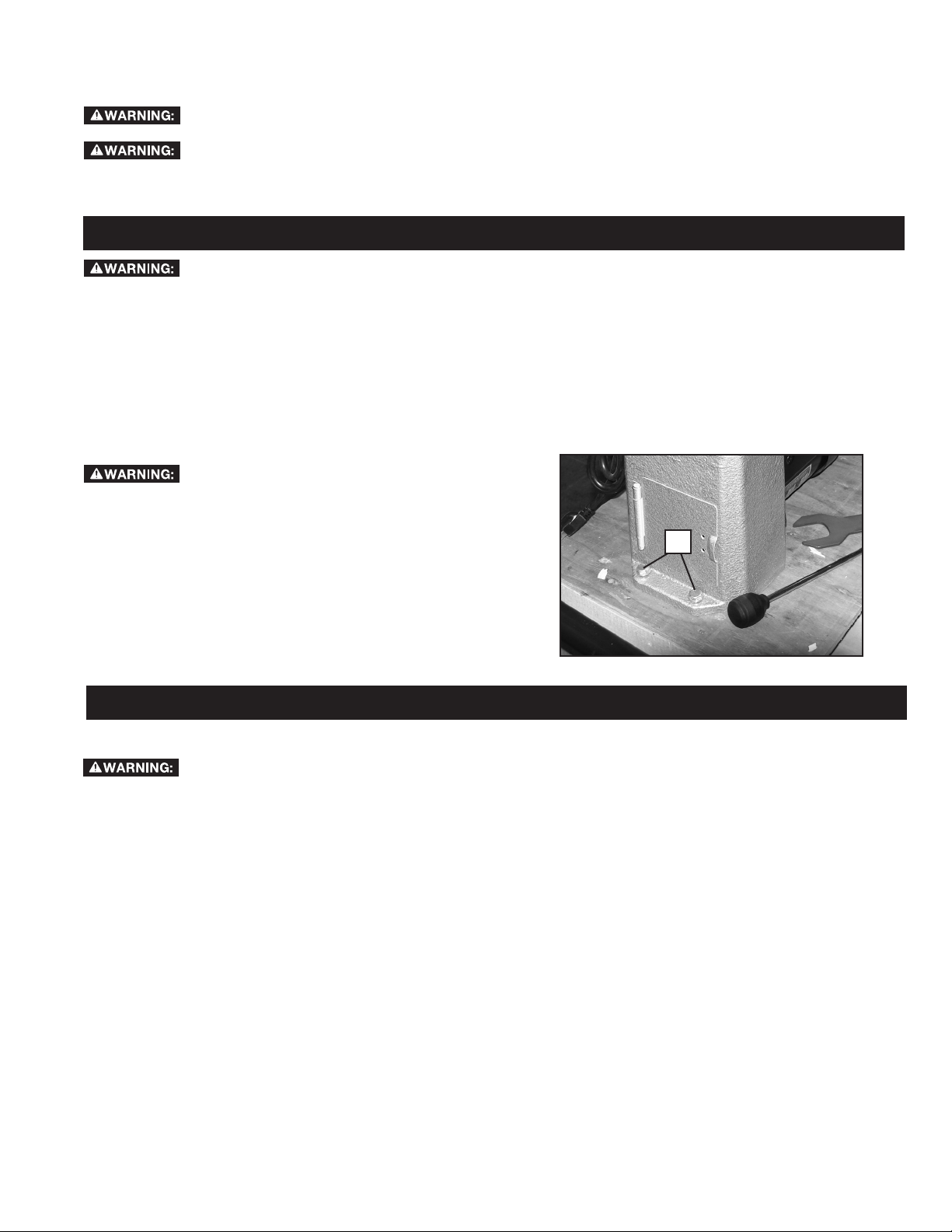
To reduce the risk of injury, the lathe
must be bolted to a secure work bench or other
sturdy surface.
Bolt lathe down using four 3/8" hex head screws (not
supplied) at the four holes in lathe base, two of which are
shown at (K) Fig. 1.
K
Fig. 1
OPERATION
To reduce the risk of injury:
• Turn unit off and disconnect it from power source before installing and removing accessories, before adjusting or
when making repairs. An accidental start-up can cause injury.
• Tighten all screws and levers securely when adjusting any part of the lathe. Also, be sure any lathe accessories are
fastened and tightened before turning on the lathe.
• When using the included 3" (76 mm) faceplate (B) Fig. 2, do not mount pieces larger than 6" (152 mm) in diameter
and up to 6" (152 mm) in length. For mounting larger pieces, be sure to use an appropriately sized faceplate.
• Keep hands off workpiece when it is spinning.
• Use only accessories recommended for this product and follow all instructions included with the accessories.
• Be sure cord is not in the way of the spinning workpiece or spinning lathe parts.
• Do not touch the tip of your turning tool directly after it has been used on the workpiece as it may be hot.
• Do not apply water or other coolants to lathe when it is spinning.
• Do not turn materials other than wood on this lathe. This lathe was designed for turning wood only.
• Be sure any chuck keys or wrenches are out of the chuck before operating the lathe.
• FOR THE DELTA® MODEL 46-460 MIDI-LATHE ONLY: Be sure to only use accessories equipped with locking set
screws for turning the lathe in reverse. Also, do not switch lathe turning directions until the workpiece comes to a
complete stop.
7
Page 8

FACEPLATE
To reduce the risk of injury, tighten all
screws and levers securely when adjusting any part of
the lathe.
To reduce the risk of injury,
included 3" (76 mm) faceplate (B) Fig. 2, do not mount
pieces larger than 6" (152 mm) in diameter and up to 6"
(152 mm) in length. For mounting larger pieces, be sure
to use an appropriately sized faceplate.
when using the
B
L
REMOVING FACEPLATE
To remove the faceplate, use the included 3 mm hex
wrench to unlock the set screws (L) at least two full turns.
Place knockout bar (H) Fig. 3 in hole (M) Fig. 2 and place
faceplate wrench (I) Fig. 3 on faceplate shoulder ats (as
shown in Fig. 3) and turn wrench to loosen faceplate.
Once loose, the faceplate (B) Fig. 2 can be unscrewed.
REPLACING FACEPLATE
FOR THE DELTA® MODEL 46-460 MIDILATHE ONLY: To reduce the risk of injury, if turning
in reverse, be sure to tighten the set screws (L) Fig. 2
securely when replacing the faceplate.
To re-attach faceplate (B) Fig. 4, screw it back on to the
spindle nose (K) and tighten securely using the knockout
bar and wrench as shown in gure 3. Replace set screws
(L) Fig. 2 if removed. Tighten set screws securely.
Directions for mounting a workpiece to the faceplate can
be found in the section Mounting the Workpiece under
MACHINE USE.
M
Fig. 2
H
I
Fig. 3
K
B
Fig. 4
8
Page 9

SPUR AND LIVE CENTERS
To reduce the risk of injury, tighten all
screws and levers securely when adjusting any part
of the lathe.
To reduce the risk of injury, be sure
the taper on the spur center (G) is clean before
mounting to the headstock spindle.
The spur center (G) Fig. 5 and live center (F) can be
used together (as shown in Fig. 5) to turn workpieces up
to 16-1/2" (419 mm) in length.
ATTACHING SPUR CENTER
Drive spur center into the workpiece using a soft mallet.
Then t spur center (G) Fig. 6 into the headstock spindle
bore (N) snugly.
NOTE: You do not need to remove the faceplate to attach
spur center.
REMOVING THE SPUR CENTER
To reduce the risk of injury, when
removing the centers, use a soft cloth to protect
against the sharp edge.
Insert knockout bar (H) Fig. 7 into spindle bore (as
shown in Fig. 7) and tap spur center (G) rmly to remove.
If necessary, tap knockout bar rmly with soft mallet.
NOTE: To avoid damage to spur center, be sure to hold
onto spur center as you tap it out.
ATTACHING LIVE CENTER
Loosen tailstock quill locking screw (O) Fig. 8. Turn
tailstock crank (P) clockwise three full turns to advance
the quill (Q). Then t the live center (F) Fig. 9 into the quill
snugly. The tailstock quill locking screw (O) Fig. 8 will be
tightened after you mount the workpiece.
G
F
Fig. 5
G
K
H
Fig. 6
H
G
REMOVING THE LIVE CENTER
To reduce the risk of injury, when
removing the centers, use a soft cloth to protect
against the sharp edge.
To eject the live center (F) Fig. 9, turn tailstock crank
(P) Fig. 8 counterclockwise to retract the quill. As quill
retracts, the live center contacts an internal ejecting pin.
When it does, you will feel the crank get harder to turn.
Turning further past this point loosens the live center for
easy removal.
Q
O
P
Fig. 7
F
Fig. 8
Fig. 9
9
Page 10

TAILSTOCK
To reduce the risk of injury, tighten all
screws and levers securely when adjusting any part
of the lathe.
ADJUSTING TAILSTOCK
To adjust the position of the tailstock (A), loosen tailstock
locking lever (R) by lifting. Slide tailstock (A) along the
bed (Fig. 11) into the desired location. Tighten tailstock
locking lever (R) Fig. 10 by pressing downward to lock in
place.
To reduce the risk of injury, don’t
position edge of tailstock (S) Fig. 11 beyond the edge
of the lathe bed (T).
REMOVING TAILSTOCK
To remove the tailstock (A) Fig. 10, unlock the tailstock
locking lever (R) and slide it off the end of the lathe bed.
LOCKING THE QUILL
The quill locking screw (O) Fig. 12 locks the quill (Q) in
place when used with the supplied live center or other
lathe accessories.
R
A
Fig. 10
A
TAILSTOCK CRANK
The tailstock crank (P) advances and retracts the quill (Q).
TOOLREST
To reduce the risk of injury, tighten all
screws and levers securely when adjusting any part
of the lathe.
To adjust the tool rest base (U) Fig. 13, loosen the tool
rest base locking lever (V) and adjust. The tool rest base
can be positioned side to side, forward and backwards
or rotated as desired. Once in position, securely lock the
base with the lever (V).
To adjust the tool rest (D), loosen the toolrest locking
screw (W). The tool rest can be positioned as desired.
Once in position, securely lock the tool rest with the lever
(V).
NOTE: if necessary, the spring-loaded locking screw
handle (W) can be ratcheted to a more convenient
position by pulling the handle outward.
S
Fig. 11
T
Q
O
P
Fig. 12
D
10
W
V
U
Fig. 13
Page 11

CHANGING LATHE SPEEDS
To reduce the risk of injury, do not
operate lathe with pulley cover door open.
For the 46-455 lathe, the lathe speed is determined by
one of ve pulley sets (See Changing Pulleys section
below.) The pulleys with the 46-455 lathe provide ve
different speed settings: 500, 950, 1550, 2700 and 4000
RPMs.
The 46-460 lathe is equipped with electronic variable
speed control. Changing among the three pulley sets
(see Changing Pulleys section below) determines
the lathe's speed range and a control knob dials the
speed up or down within that range. The pulleys with
the 46-460 lathe provide three different speed ranges:
250-750 RPMs, 600-1800 RPMs and 1350-4000 RPMs.
CHANGING PULLEYS (46-455 and 46-460)
To reduce the risk of injury, do not
operate lathe with pulley cover door open.
To move the belt between pulleys:
1. Lift up pulley cover (X) Fig. 14.
2. Pull down belt tensioning lever (Y) Fig. 15 to release
belt tension.
3. Open lower side door (AA) Fig. 16 and move belt to
desired pulley set according to the speed chart on
inside of pulley cover (X) Fig. 14 NOTE: Be sure the
grooves on the inside of the belt (BB) Fig. 17 fully
engage the grooves (CC) on both pulleys and that
the belt does not hang off the edge of the pulley.
4. Lift belt tensioning lever (Y) Fig. 15 up until it snaps
into place.
5. Close both the lower side door (AA) Fig. 16 and the
pulley cover (X) Fig. 14 securely.
To adjust belt tension:
X
Fig. 14
Y
Fig. 15
SPEED RECOMMENDATIONS FOR MIDI LATHE
The following guidelines are approximate
and must be reduced if the piece you are working on
is out of balance. These speeds are only for side grain
pieces. Reduce speed and take special care when cutting
end grain.
RECOMMENDED SPEEDS (RPMs)
Roughing Finishing
Diameter of work
Under 2 in.
(51 mm)
2 in. to 4 in.
(51 mm to 107 mm)
4 in. to 6 in.
(107 mm to 152 mm)
6 in. to 8 in.
(152 mm to 203 mm)
8 in. to 10 in.
(203 mm to 254 mm)
10 in. to 12 in.
(254 mm to 305 mm)
Low High Low High
950 1500 1900 3000
500 750 1500 2300
500 750 1500 2300
250 500 900 1500
250 500 900 1500
250 500 900 1500
CC
AA
Fig. 16
BB
Fig. 17
Fig. 18
11
Page 12

NOTE: The belt tension is pre-set at the factory and
should only require adjusting if the belt stretches over
time or is replaced.
1. Open pulley cover (X) Fig. 14 and side door (AA) Fig. 16.
2. Pull down belt tensioning lever (Y) Fig. 15 to release
belt tension. Do not lock it below the tab (Z).
3. Turn thumbwheel (DD) Fig. 19 clockwise to increase
tension, or counterclockwise to decrease tension.
NOTE: A properly tensioned belt should deflect
approximately 1/4" (6.4 mm) with moderate finger
pressure.
4. Lift lever (Y) Fig. 15 and snap into place.
5. Close lower side door (AA) Fig. 16 and pulley cover
(X) Fig. 14 securely.
DD
Fig. 19
ELECTRONIC VARIABLE SPEED CONTROL
(46-460 ONLY)
Once you select a speed range (as described above
in Changing Pulleys section), use the speed control
knob (EE) Fig. 20 to vary the speed within that range. As
you face the lathe, turn knob forwards (towards you) to
increase speed, turn it backwards (or away from you) to
decrease speed.
To reduce the risk of injury, always
set the speed control knob to its lowest setting
before starting the lathe. Never start a workpiece at
maximum speed.
INDEXING PIN
The lathe is equipped with an indexing pin (FF) Fig. 21.
The pin allows the spindle (GG) to be locked in 24
positions—as labeled on indexing wheel (HH)—for use
in various operations. To use:
1. Rotate idexing wheel (HH) so spindle (GG) is in
desired location.
2. Pull back index pin (FF) slightly from retaining
groove.
3. Rotate indexing pin 90 degrees so the crosspin (II)
lines up with recess, as shown in Fig. 21a.
4. Release indexing pin (FF) so that it engages
numbered indexing wheel (HH) Fig. 21 and locks
spindle (GG) in place.
Do not turn on lathe with index pin
engaged. Doing so could damage the lathe.
EE
Fig. 20
HH
FF
GG
Fig. 21
Do not use the index pin (FF) to lock
spindle when removing faceplate because this can
damage the pin. To remove faceplate, follow directions
under Removing Faceplate section.
II
FF
Fig. 21a
12
Page 13

STARTING AND STOPPING LATHE
To reduce the risk of injury, make sure
that the ON/OFF switch is in the "OFF" position before
plugging cord into outlet. Do not touch the plug’s
metal prongs when unplugging or plugging in the
cord.
To turn lathe on, lift switch paddle (JJ) Fig. 22 up to the
"ON" position. To turn lathe off, push switch paddle down
to the "OFF" position
LOCKING SWITCH IN THE "OFF" POSITION
JJ
To reduce the risk of injury, in the event
of a power outage (such as a breaker or fuse trip),
always move the switch to the “OFF” position until
the main power is restored.
IMPORTANT: When the machine is not in use, the
switch should be locked in the "OFF" position to prevent
unauthorized use, using a padlock (KK) Fig. 23 with a 1/4"
(6.4 mm) diameter shackle.
MOTOR OVERLOAD PROTECTOR
The tool is equipped with a manual reset circuit breaker.
If the tool is overloaded or stalled too long the circuit
breaker will trip causing the tool to shut off.
To restart:
1. Set the ON/OFF switch to "OFF"
2. Allow the motor to cool 3-5 minutes.
3. Press the reset button (LL) Fig. 24.
4. Resume normal operations.
Fig. 22
KK
Fig. 23
13
LL
Fig. 24
Page 14

MACHINE USE
To reduce the risk of injury:
• Tighten all screws and levers securely when adjusting
any part of the lathe. Also, be sure any lathe accessories
are fastened and tightened before turning on the lathe.
• When using the included 3" (76 mm) faceplate (B)
Fig.25, do not mount pieces larger than 6" (152 mm) in
diameter and up to 6" (152 mm) in length. For mounting
larger pieces, be sure to use an appropriately sized
faceplate.
• Keep hands off workpiece when it is spinning.
• Use only accessories recommended for this product
and follow all instructions included with the accessories.
• Be sure cord is not in the way of the spinning workpiece
or spinning lathe parts.
• Do not touch the tip of your turning tool directly after
it has been used on the workpiece as it may be hot.
• Do not apply water or other coolants to lathe when it is
spinning.
• Do not turn materials other than wood on this lathe. This
lathe was designed for wood turning only.
• Be sure any chuck keys or wrenches are out of the
chuck before operating the lathe.
• FOR THE DELTA® MODEL 46-460 MIDI-LATHE
ONLY: Be sure to only use accessories equipped with
locking set screws for turning the lathe in reverse. Also,
do not switch lathe turning directions until the workpiece
comes to a complete stop.
MOUNTING THE WORKPIECE
NOTE: When mounting a workpiece, first tap the spur
center into the workpiece using a soft mallet before installing
into headstock.
B
Fig. 25
Fig. 26
E
O
P
A typical bowl mount is shown in Fig. 25. Workpieces can
be mounted to the faceplate through the faceplate's four
holes using screws appropriate for the type of wood being
turned.
Another type of workpiece mount, where the workpiece is
xed between the spur and live centers, is shown in Fig.26.
Here are some tips on this mount:
1. Mount the workpiece by moving the tailstock to a
position about 1" or 1-1/2" (25 mm or 38 mm) from the
end of the workpiece and locking it in this position.
2. Advance the live center (E) by turning the tailstock crank
(P) Fig. 27 until the center cup makes contact with the
workpiece.
3. Do not support the workpiece on the center pin alone.
Always have the rim of the center cup imbedded at least
1/8" (3.2 mm) into the workpiece.
4. Lock the quill locking screw (O).
Fig. 27
14
Page 15

TURNING IN REVERSE (46-460 ONLY)
FOR THE DELTA® MODEL 46-460 MIDI-
LATHE ONLY: To reduce the risk of injury, be sure
to only use accessories equipped with locking set
screws for turning the lathe in reverse. Also, do not
switch lathe turning directions until the workpiece
comes to a complete stop.
Care should be taken not to stall the
workpiece when turning in reverse. If a stall should
occur, stop the lathe and verify that the chuck or
faceplate is fully seated and both set screws are
tight before continuing.
MM
The lathe comes ready to turn forward (downwards
toward the user) for typical woodturning applications.
However, some applications require the lathe to turn in
reverse (upwards away from user). The 46-460 can turn
in reverse. To do this:
1. Be sure the lathe power switch is turned off and that
the spindle is not spinning.
2. Slide switch (MM) Fig. 28 to “FWD” (forward) or
“REV” (reverse) position, depending on your desired
rotation.
NOTE: The forward/reverse switch (marked FWD/ REV)
employs a lockout feature to prevent switching directions
when the ON/OFF switch is in the raised, or "ON"
position.
3. If using a faceplate, chuck or other accessory that
must be screwed on to the spindle nose, be sure the
set screws are securely tightened before running in
reverse.
Fig. 28
TROUBLESHOOTING
For assistance with your machine, visit our website at www.DeltaMachinery.com for a list of service centers or call the
DELTA® Power Equipment Corporation help line at 1-800-223-7278
MAINTENANCE
To reduce the risk of injury, turn unit off and disconnect it from power source before installing and removing
accessories, before adjusting or when making repairs. An accidental start-up can cause injury.
KEEP MACHINE CLEAN
Periodically blow out all air passages with dry compressed air. All plastic parts should be cleaned with a soft damp
cloth. NEVER use solvents to clean plastic parts. They could possibly dissolve or otherwise damage the material.
To reduce the risk of injury, wear certied safety equipment for eye, hearing and respiratory protection
while using compressed air.
FAILURE TO START
Should your machine fail to start, check to make sure the prongs on the cord plug are making good contact in the outlet.
Also, check for blown fuses or open circuit breakers in the line.
LUBRICATION & RUST PROTECTION
Apply household oor paste wax to the machine table, extension table or other work surface weekly. Or use a commercially
available protective product designed for this purpose. Follow the manufacturer’s instructions for use and safety.
To clean cast iron tables of rust, you will need the following materials: a medium sized scouring pad, a can of spray
lubricant and a can of degreaser. Apply the spray lubricant and polish the table surface with the scouring pad. Degrease
the table, then apply the protective product as described above.
15
Page 16
PERIODIC MAINTENANCE
• Check that all fasteners are tightened properly.
• Check belt tension and adjust if necessary. See Changing Pulleys for instructions.
• Inspect belt for damage or wear and replace as needed. See below for belt replacement instructions.
• Inspect both faceplate set screws to ensure the cup edge is sharp and crisp. Replace if necessary.
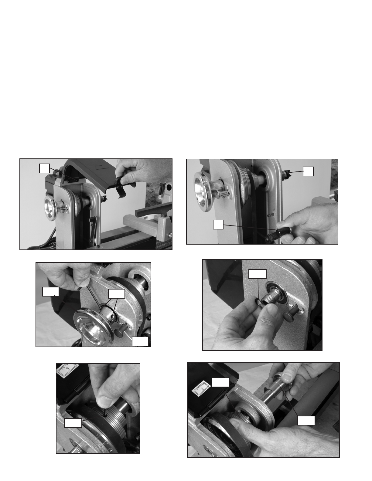
BELT REPLACEMENT
1. Lift up pulley cover (X) Fig. 29.
2. Pull down belt tensioning lever (Y) Fig. 30 to release belt tension.
3. Remove spur center (G) Fig. 30, if attached.
4. Loosen two set screws (NN) Fig. 31 on the spindle handwheel (OO) Fig. 31 at least 2-3 turns to avoid damage
to the threads during removal.
5. Engage indexing pin (FF) Fig. 31 and remove spindle handwheel (OO). (NOTE: Threads are left-hand. Turn
handwheel clockwise to loosen and remove.)
6. Remove wave spring (PP) Fig. 32.
7. Loosen spindle pulley set screw (QQ) Fig. 33 with included hex wrench.
8. Grasp spindle pulley (RR) Fig. 34 with one hand and slide spindle shaft (SS) out with other hand in the tailstock
direction.
9. Remove old belt and replace.
X
OO
Fig. 29
Fig. 31
G
Y
Fig. 30
PP
NN
FF
Fig. 32
QQ
Fig. 33
RR
SS
Fig. 34
16
Page 17

10. Place new belt on spindle pulley making sure
grooves in belt align with grooves in pulley.
11. Place spindle pulley (RR) inside headstock (as
shown in Fig. 35) and hold as you insert the
spindle shaft (SS) through headstock and pulley.
Take care to align the shaft key (TT) with the
pulley keyway (not shown).
12. Be sure the pulley seats rmly against the shaft
shoulder (UU).
13. Tighten pulley set screw (QQ) Fig. 33 rmly.
14. Reinstall wave spring (PP) Fig. 32 and
handwheel (OO) Fig. 31. Handwheel tightens
counterclockwise. Tighten handwheel completely,
then back off 1/4 turn. NOTICE: DO NOT OVER
TIGHTEN. Doing so could damage the bearings.
15. Tighten two handwheel set screws (NN) Fig. 31
securely. With belt hanging loose, rotate spindle
to ensure it turns freely.
16. Lift belt tensioning lever (Y) Fig. 30 up and snap
it into place.
1 7. Check belt tension and adjust if needed. (See
Changing Pulleys section.)
18. Close pulley cover (X) Fig. 29 and side door
(AA) Fig. 16 securely.
19. Disengage indexing pin (FF) Fig. 31 if it was
engaged to remove spindle handwheel (OO).
To reduce the risk of injury, do not
operate lathe with pulley cover door open.
Do not turn on lathe with index pin
engaged. Doing so could damage the lathe.
RR
TT
Fig. 35
UU
SS
REPLACEMENT PARTS
Use only identical replacement parts. For a parts list or to order parts, visit our website at
can also order parts from your nearest factory-owned branch, or by calling our Customer Care Center at 1-800-223-7278 to receive
personalized support from highly-trained technicians.
www.DeltaMachinery.com/service.
Yo u
FREE WARNING LABEL REPLACEMENT
If your warning labels become illegible or are missing, call
1-800-223-7278
for a free replacement.
SERVICE AND REPAIRS
All quality tools will eventually require servicing and/or replacement of parts. For information about DELTA® Power Equipment
Corporation, its factory-owned branches, or an Authorized Warranty Service Center, visit our website at www.DeltaMachinery.com
or call our Customer Care Center at 1-800-223-7278. All repairs made by our service centers are fully guaranteed against defective
material and workmanship. We cannot guarantee repairs made or attempted by others.
You can also write to us for information at DELTA® Power Equipment Corporation, 99 Roush Street, Anderson, South Carolina
29625. - Attention: Product Service. Be sure to include all of the information shown on the nameplate of your tool (model number,
type, serial number, etc.)
17
Page 18

ACCESSORIES
Since accessories other than those offered by DELTA® have not been tested with this product,
use of such accessories could be hazardous. For safest operation, only DELTA® recommended accessories
should be used with this product.
A complete line of accessories is available from your DELTA® Supplier, DELTA® Factory Service Centers, and DELTA®
Authorized Service Stations. Please visit our Web Site www.DeltaMachinery.com for a catalog or for the name of your
nearest supplier.
To register your tool for warranty service visit our website at www.DeltaMachinery.com.
Five Year Limited New Product Warranty
DELTA® will repair or replace, at its expense and at its option, any new DELTA® machine, machine part, or machine accessory which in normal
use has proven to be defective in workmanship or material, provided that the customer returns the product prepaid to a DELTA
center or authorized service station with proof of purchase of the product within five years and provides DELTA® with reasonable opportunity
to verify the alleged defect by inspection. For all refurbished DELTA® product, the warranty period is 180 days. DELTA® will not be responsible
for any asserted defect which has resulted from normal wear, misuse, abuse or repair or alteration made or specifically authorized by anyone
other than an authorized DELTA® service facility or representative. Under no circumstances will DELTA® be liable for incidental or consequential
damages resulting from defective products. Some states do not allow the exclusion or limitation of incidental or consequential damages, so the
above limitation or exclusion may not apply to you. This warranty is DELTA®'s sole warranty and sets forth the customer’s exclusive remedy,
with respect to defective products; all other warranties, express or implied, whether of merchantability, fitness for purpose, or otherwise, are
expressly disclaimed by DELTA®. For further detail of warranty coverage and warranty repair information, visit www.DeltaMachinery.com or
call 1-800-223-7278. This warranty gives you specific legal rights and you may have other rights which vary in certain states or provinces.
®
factory service
LATIN AMERICA: This warranty does not apply to products sold in Latin America. For products sold in Latin America,
see country specic warranty information contained in the packaging, call the local company or see website for warranty
information.
18
Page 19

LES INSTRUCTIONS IMPORTANTES DE SURETE
Si vous avez n'importe quelles questions relatives à son application n'utilisent pas le produit jusqu'à ce que
vous avez écrit DELTA® Power Equipment Corporation et nous vous avons conseillé. La forme en ligne de
contact à www.DeltaMachinery.com Courrier Postal: Technical Service Manager, DELTA® Power Equipment
Corporation, 99 Roush Street, Anderson, South Carolina 29625.
Information en ce qui concerne l'opération sûre et correcte de cet outil est disponible des sources suivantes:
• Power Tool Institute, 1300 Sumner Avenue, Cleveland, OH 44115-2851 ou en ligne www.powertoolinstitute.com
• National Safety Council, 1121 Spring Lake Drive, Itasca, IL 60143-3201
• American National Standards Institute, 25 West 43rd Street, 4 oor, New York, NY 10036 www.ansi.org - ANSI 01.1
Safety Requirements for Woodworking Machines
• U.S. Department of Labor regulations www.osha.gov
MESURES DE SÉCURITÉ - DÉFINITIONS
Ce guide contient des renseignements importants que vous deviez bien saisir. Cette information porte sur VOTRE
SÉCURITÉ et sur LA PRÉVENTION DE PROBLÈMES D’ÉQUIPEMENT. An de vous aider à identier cette information,
nous avons utilisé les symboles ci-dessous. Veuillez lire attentivement ce guide en portant une attention particulière à ces
sections.
Indique une situation dangereuse imminente qui, si elle n’est pas évitée, causera la mort ou des bles-
sures graves.
Indique une situation potentiellement dangereuse qui, si elle n’est pas évitée, pourrait se solder par un
décès ou des blessures graves.
Indique une situation potentiellement dangereuse qui, si elle n’est pas évitée pourrait se solder par des
blessures mineures ou modérées.
indique une pratique ne posant aucun risque de dommages corporels mais qui par contre, si rien
n’est fait pour l’éviter, pourrait poser des risques de dommages matériels.
Les scies, meules, ponceuses, perceuses ou autres outils de construction peuvent produire
des poussières contenant des produits chimiques reconnus par l’État californien pour causer cancers,
malformations congénitales ou être nocifs au système reproducteur. Parmi ces produits chimiques, on retrouve :
• le plomb dans les peintures à base de plomb ;
• la silice cristallisée dans les briques et le ciment ou autres articles de maçonnerie ; et
• l’arsenic et le chrome dans le bois ayant subi un traitement chimique (ACC).
Le risque associé à de telles expositions varie selon la fréquence à laquelle on effectue ces travaux. Pour réduire toute
exposition à ces produits : travailler dans un endroit bien aéré, en utilisant du matériel de sécurité homologué tel un
masque antipoussières spécialement conçu pour ltrer les particules microscopiques.
19
Page 20

RÈGLES DE SÉCURITÉ GÉNÉRALES
L’inobservation de ces règles peut conduire à des blessures graves.
1. Pour sa sécurité personnelle, lire la notice d’utilisation,
avant de mettre la machine. En marche, et pour aussi
apprendre l’application et les limites de la machine ainsi
que les risques qui lui sont particuliers ainsi, les possibilités
d’accident et de blessures seront beaucoup réduites.
2. Portez des dispositifs de protection des yeux et de
l'ouïe. Utilisez toujours des lunettes de sécurité. Des
lunettes ordinaires ne constituent pas des lunettes de
sécurité. Utilisez des équipements de sûreté homologués.
Les dispositifs de protection des yeux doivent être conformes
aux normes ANSI Z87.1. Les dispositifs de protection de
l'ouïe doivent être conformes aux normes ANSI S3.19.
3. Porter une tenue appropriée. Pas de cravates, de gants,
ni de vêtements amples. Enlever montre, bagues et autres
bijoux. Rouler les manches. Les vêtements ou les bijoux qui
se trouvent pris dans les pièces mobiles peuvent entraîner
des blessures.
4. Ne pas utiliser la machine dans un environnement
dangereux. L’utilisation d’outils électriques dans des endroits
humides ou sous la pluie peut entraîner des décharges
électriques ou une électrocution. Garder la zone de travail
bien éclairée pour éviter de trébucher ou d’exposer les
doigts, les mains ou les bras à une situation dangereuse.
5. Ne pas utiliser d’outils électriques à proximité
de liquides inflammables ou dans une atmosphère
gazeuse ou explosive. Les moteurs et interrupteurs des
outils pourraient provoquer des étincelles et enammer des
vapeurs.
6. Garder les outils et les machines en parfait état. Garder
les outils affûtés et propres an d’obtenir le meilleur et le
plus sûr rendement. Suivre les instructions pour lubrifier
et changer les accessoires. Les outils et les machines mal
entretenus peuvent se dégrader davantage, et/ou entraîner
des blessures.
7. Inspecter les pièces pour déceler tout dommage. Avant
d’utiliser la machine, la vérier pour voir s’il n’y a pas de
pièces endommagées. Vérifier l’alignement des pièces
mobiles et si ces pièces ne se coincent pas, la rupture
de pièces, ou toute autre condition pouvant en affecter le
fonctionnement. Toute pièce ou protecteur endommagé doit
être réparé ou remplacé avec le DELTA® ou les pièces de
rechange autorisées par usine. Les pièces endommagées
peuvent dégrader davantage la machine et/ou entraîner des
blessures.
8. Garder l’aire de travail propre. Les zones et établis
encombrés favorisent les accidents.
9. Garder les enfants et les visiteurs à distance. L’atelier
est un lieu potentiellement dangereux. Les enfants et les
visiteurs peuvent se blesser.
10. Éviter le démarrage accidentel. S’assurer que l’interrupteur
est sur « OFF » (ARRÊT) avant de brancher le cordon. En
cas de coupure de courant, placer l’interrupteur à la position
«OFF » (ARRÊT). Un démarrage accidentel peut entraîner
des blessures.
11. Utiliser les dispositifs protecteurs. Vérier que tous les
dispositifs protecteurs sont bien en place, bien xés et en
bon état de marche pour éviter les blessures.
12. Enlever les clés de réglage et celles de serrage avant de
mettre la machine en marche. Les outils, les chutes et les
autres débris peuvent être projetés violemment et blesser.
13. Utiliser la bonne machine. Ne pas forcer la machine ou
l’accessoire à faire un travail pour lequel il n’a pas été conçu.
Des dommages à la machine et/ou des blessures pourraient
s’ensuivre.
14. Utiliser les accessoires recommandés. L’utilisation
d’accessoires non recommandés par DELTA® peut
endommager la machine et blesser l’utilisateur.
15. Utiliser le cordon prolongateur approprié. S’assurer que
le cordon prolongateur est en bon état. Lorsqu’un cordon
prolongateur est utilisé, s’assurer que celui-ci est d’un
calibre suffisant pour l’alimentation nécessaire à la machine.
Un cordon d’un calibre insuffisant entraînera une perte de
tension d’où une perte de puissance et surchauffe. Voir
le Tableau sur Les Cordons prolongateurs pour obtenir le
calibre approprié selon la longueur du cordon et l’ampérage
de la machine. S’il y a un doute, utiliser un cordon d’un
calibre supérieur. Plus le chiffre est petit, plus le l est gros.
16. Fixer la pièce. Utilisez les brides ou un étau pour tenir
l'objet si pratique. La perte de commande d'un objet peut
causer des dommages.
1 7. Avancer la pièce dans le sens contraire à la rotation
de la lame, de la fraise ou de la surface abrasive.
L’alimentation dans l’autre sens peut entraîner une
projection violente de la pièce.
18. Ne pas forcer la machine en avançant la pièce trop vite.
Des dommages et/ou des blessures peuvent s’ensuivre.
19. Ne pas se pencher au-dessus de la machine. Une perte
de l’équilibre peut entraîner une chute sur la machine en
marche et causer des blessures.
20. Ne jamais monter sur la machine. On peut se blesser
gravement si la machine bascule ou si l’on touche
accidentellement son outil tranchant.
2 1. Ne jamais laisser la machine en marche sans
surveillance. Couper le courant. Ne pas quitter la
machine tant qu’elle n’est pas complètement arrêtée. Un
enfant ou un visiteur pourrait se blesser.
22. Mettre la machine à l’arrêt « OFF » et la débrancher
avant d’installer ou d’enlever des accessoires, changer
les coupeurs, d’ajuster ou de changer des montages.
En dépannant, soyez sûr de fermer le commutateur de
début en position de « OFF ». Un démarrage accidentel
peut entraîner des blessures.
23. Mettre l’atelier à l’abri des enfants au moyen de
cadenas, d’interrupteurs principaux ou en enlevant
les boutons des dispositifs de mise en marche. Le
démarrage accidentel de la machine par un enfant ou un
visiteur peut entraîner des blessures.
24. Rester vigilant, attentif, et faire preuve de bon sens. Ne
pas utiliser la machine lorsque l’on est fatigué ou sous
l’inuence de drogues, d’alcool ou de médicaments. Un
instant d’inattention lors de l’utilisation d’outils électriques
peut entraîner des blessures graves.
25. L'utilisation de cet outil peut
produire et disperser de la poussière ou d'autres
particules en suspension dans l'air, telles que
la sciure de bois, la poussière de silicium cristallin
et la poussière d'amiante. Dirigez les particules loin
du visage et du corps. Faites toujours fonctionner l'outil
dans un espace bien ventilé et prévoyez l'évacuation
de la poussière. Utilisez un système de dépoussiérage
chaque fois que possible. L'exposition à la poussière peut
causer des problèmes de santé graves et permanents,
respiratoires ou autres, tels que la silicose (une maladie
pulmonaire grave) et le cancer, et même le décès de la
personne affectée. Évitez de respirer de la poussière et
de rester en contact prolongé avec celle-ci. En laissant la
poussière pénétrer dans vos yeux ou votre bouche, ou en la
laissant reposer sur votre peau, vous risquez de promouvoir
l'absorption de substances toxiques. Portez toujours des
dispositifs de protection respiratoire homologués par niosh/
osha, appropriés à l'exposition à la poussière et de taille
appropriée, et lavez à l'eau et au savon les surfaces de
votre corps qui ont été exposées.
20
Page 21

RÈGLES SPÉCIFIQUES ADDITIONNELLES DE SÛRETÉ
L’inobservation de ces règles peut conduire à des blessures graves.
1. NE PAS FAIRE FONCTIONNER CETTE MACHINE AVANT
QU’elle ne soit assemblée et installée conformément à ces
directives.
2. SI VOUS NE MAÎTRISEZ PAS PARFAITEMENT
L’UTILISATION DE CET APPAREIL, DEMANDEZ
CONSEIL à un superviseur, instructeur, ou toute autre
personne qualiée.
3. SUIVRE TOUS LES CODES DE CÂBLAGE et les
connexions électriques recommandés.
4. DÉGROSSIR LA PIÈCE pour lui donner la forme la plus
proche de la forme nale avant de la placer sur le plateau de
montage.
5. VÉRIFIER QUE LA PIÈCE NE PRÉSENTE PAS DE
DÉFAUT et tester les joints de colle avant de monter la
pièce sur la machine. NE PAS monter une pièce fendue ou
présentant un nœud.
6. FIXER FERMEMENT LA PIÈCE au plateau de montage
avant le tournage sur plateau. Utiliser un plateau de montage
de dimension appropriée pour soutenir la pièce. Les attaches
à vis ne doivent pas gêner l’outil de tournage aux dimensions
nales de la pièce.
7. NE JAMAIS DIRIGER LA PIÈCE vers la pointe
d’entraînement tant que la pointe d’entraînement est dans la
poupée xe. Insérer la pointe d’entraînement dans la pièce à
l’aide d’un maillet avant de l’installer sur la poupée xe.
8. AJUSTER ET BLOQUER LA CONTREPOINTE contre la
pièce. Lubrier la contrepointe si elle ne présente pas de
roulement à billes.
9. AJUSTER CORRECTEMENT LA HAUTEUR DU PORTE-
OUTIL.
10. AJUSTER LE PORTE-OUTIL de façon à ce qu’il soit aussi
près que possible de la pièce.
11. SERRER TOUTES LES POIGNÉES DE VERROUILLAGE
DES FIXATIONS avant d’utiliser l’outil.
12. TOURNER LA PIÈCE MANUELLEMENT pour vérier le
dégagement avant de mettre la machine en marche.
13. S’ASSURER QU’AUCUN OBJET NE SE TROUVE SUR LE
BANC DU TOUR (outils, chutes de bois, etc.) avant de mettre
la machine sous tension.
14. VÉRIFIER LE RÉGLAGE SOIGNEUSEMENT avant de
mettre la machine en marche.
15. SE TENIR SUFFISAMMENT À L’ÉCART ET ÉLOIGNER
LES OBSERVATEURS de la trajectoire de rotation de la
pièce afin d’éviter toute blessure due à la projection de
débris.
16. UTILISER LA VITESSE LA PLUS FAIBLE lorsque vous
commencez à travailler sur une nouvelle pièce. NE JAMAIS
DÉPASSER les vitesses recommandées.
1 7. NE JAMAIS AJUSTER LE PORTE-OUTIL alors que la
pièce tourne.
18. NE JAMAIS DESSERRER LE FOURREAU ou la poupée
mobile alors que la pièce tourne.
19. ENGAGER LENTEMENT L’OUTIL DE COUPE DANS LA
PIÈCE, et couper de petites quantités pour le dégrossissage.
20. ÔTER LE PORTE-OUTIL avant le ponçage ou le polissage.
2 1. NE JAMAIS EFFECTUER D’OPÉRATIONS DE TRAÇAGE,
d’assemblage, ou de réglage sur la table/l’espace de travail
lorsque la machine est en marche.
22. ÉTEINDRE LA MACHINE ET LA DÉBRANCHER de
la source d’alimentation avant d’ajouter ou d’enlever des
accessoires, avant d’ajuster ou de modier les réglages, ou
lors d’une réparation.
23. ÉTEINDRE L’APPAREIL, le débrancher et nettoyer la table/
l’espace de travail avant de quitter. AFIN D’ÉVITER TOUTE
UTILISATION NON AUTORISÉE, verrouiller l’interrupteur en
position ARRÊT «OFF».
24. LORS DE TOUT RÉGLAGE EFFECTUÉ SUR LE TOUR,
SERREZ SOLIDEMENT TOUTES LES VIS ET TOUS
LES LEVIERS. S’assurer également de bien xer tous les
accessoires du tour avant de le faire démarrer.
25. LORS DE L’UTILISATION DE LA PLAQUE DE MONTAGE
DE 76MM (3 PO) COMPRISE, NE PAS MONTER DE
PIÈCES DE PLUS DE 152MM (6 PO) DE DIAMÈTRE,
et de plus de 152mm (6po) de longueur. Pour le montage
de pièces plus importantes, s’assurer d’utiliser la plaque de
montage de la taille appropriée.
26. TENIR LES MAINS À L’ÉCART DE LA PIÈCE lors du
tournage.
2 7. UTILISER UNIQUEMENT LES ACCESSOIRES
RECOMMANDÉS POUR CE PRODUIT et respecter toutes
les directives fournies avec ceux-ci.
28. S’ASSURER QUE LE CORDON D’ALIMENTATION N’EST
PAS SUR LA TRAJECTOIRE de la pièce en rotation ou
d’une pièce du tour en mouvement.
29. NE PAS TOUCHER DIRECTEMENT L’EXTRÉMITÉ DE
L’OUTIL DE TOURNAGE après son utilisation sur la
pièce. En effet, elle risque d’être brûlante.
30. NE PAS APPLIQUER D’EAU OU D’AUTRES LIQUIDES DE
REFROIDISSEMENT SUR LE TOUR alors qu’il fonctionne.
3 1. UTILISER UNIQUEMENT DU BOIS AVEC CE TOUR. En
effet, l’appareil est conçu uniquement pour le tournage du
bois.
32. S’ASSURER QUE TOUTES LES CLÉS DE MANDRIN
OU LES CLÉS SONT RETIRÉES DU MANDRIN avant de
mettre le tour sous tension.
33. UNIQUEMENT POUR LE TOUR, MODÈLE 46-460 MIDI-
LATHE, DE DELTA : s’assurer d’utiliser uniquement des
accessoires munis d’une vis de calage verrouillable pour
utiliser le tour en marche arrière. De plus, veuillez attendre
l’arrêt complet de la pièce avant de modifier le sens de
rotation.
34. DES INFORMATIONS SUPPLÉMENTAIRES (c.-à-d., une
vidéo sur la sécurité), indiquant comment utiliser des outils
électriques correctement et en toute sécurité, sont disponibles
auprès du Power Tool Institute, 1300 Sumner Avenue,
Cleveland, OH 44115-2851 É.-U. (www.powertoolinstitute.
com). Des renseignements sont également offerts par le
National Safety Council, 1121 Spring Lake Drive, Itasca,
IL 60143-3201 É.-U. Se reporter à la norme ANSI 01.1 de
l’American National Standards Institute concernant les
machines de travail du bois, ainsi que la réglementation
OSHA 1910.213 du département américain du travail.
CONSERVER CES DIRECTIVES.
Les consulter souvent et les utiliser pour donner des directives aux autres.
21
Page 22

RACCORDEMENTS ÉLECTRIQUES
Un circuit électrique séparé doit être utilisé pour les machines. Ce circuit doit utiliser un câble de calibre 12 au minimum et doit
être protégé par un fusible temporisé. REMARQUE : les fusibles temporisés devraient avoir l’inscription « D » au Canada et
« T » aux É.-U. Si on utilise un cordon prolongateur, ce cordon doit être à trois ls, avoir uneche à trois broches et une prise
de courant à trois cavités, mise à la terre qui correspond à la che de la machine. Avant debrancher la machine, s’assurer que
l’interrupteur (les interrupteurs) se trouve(nt) en position ARRÊT « OFF » et que le courantélectrique présente les mêmes
caractéristiques que celles qui sont inscrites sur la machine. Toutes les connexions électriquesdoivent établir un bon contact. Le
fonctionnement sur une basse tension endommagera la machine.
Ne pas exposer la machine à la pluie, et ne pas l’utiliser dans des endroits humides.
SPÉCIFICATIONS DU MOTEUR
Cette machine est câblée pour un fonctionnement sur un courant alternatif de 120 volts 60 Hz. Avant de brancher la machine,
s’assurer que l’interrupteur se trouve à la position ARRÊT « OFF ».
INSTRUCTIONS DE MISE À LA TERRE
Pour réduire le risque de blessures,
afin de protégerl’utilisateur des décharges électriques
1. Toutes les machines avec cordon mis à la terre: Dans l’éventualité d’un mauvais fonctionnement ou d’unepanne, la
mise à la terre fournit un trajet de moindre résistance permettant de réduire le risque de décharge électrique. Cette machine
est dotée d’un cordon électrique possédant unconducteur de mise à la terre de l’équipement ainsi que d’uneche mise à la
terre. La che doit être branchée dans une prisede courant correspondante, installée de façon adéquate etmise à la terre
conformément à tous les codes et règlements locaux.
Ne pas modier la che fournie - si elle ne s’adapte pas à laprise de courant, il faut faire installer une prise de courant
convenable par un électricien compétent.
Un mauvais raccordement du conducteur de mise à la terrede l’équipement peut entraîner un risque de décharge
électrique. Le conducteur possédant un isolant avec surface extérieure de couleur verte, avec ou sans rayures jaunes,
estle conducteur de mise à la terre de l’équipement. Si uneréparation ou un remplacement du cordon électrique s’avère
nécessaire, ne pas brancher le conducteur de mise à la terrede l’équipement à une borne sous tension.
Consulter un électricien compétent ou le personnel de service après-vente si on ne comprend pas entièrement les
instructions de mise à la terre, ou si l’on doute que la machines oit correctement mise à la terre.
Utiliser seulement des cordons prolongateurs à trois ls dotésd’une che mise à la terre, à trois broches, et de prises à
troiscavités convenant à la che de la machine, comme l’illustre lagure A.
Réparer ou remplacer sans délai tout cordon endommagé ouusé.
Cette machine doit être mise à la terre pendant son emploi,
2. Machines avec cordon mis à la terre prévues pour uneutilisation sur une alimentation nominale inférieure à 150
volts :Si cette machine est prévue pour être utilisée sur un circuit quicomporte une prise semblable à celle illustrée à
la gure A, la machine devra comporter une che mise à la terre semblableà celle illustrée à la gure A. Un adaptateur
temporaire semblable à celui illustré à la gure B, peut être utilisé pour raccorder cette che à une prise à deux cavités
comme celle illustrée à la gure B, si une prise correctement mise à la terren’est pas disponible. L’adaptateur temporaire
ne doit êtreutilisé que jusqu’au moment où une prise correctement miseà la terre est installée par un électricien compétent.
L’oreillerigide ou autre dispositif semblable de couleur verte, sur ledessus de l’adaptateur, doit être connecté sur une
mise à laterre permanente comme, par exemple une boîte à prisescorrectement mise à la terre. Quand un adaptateur est
utilisé,celui-ci doit être retenu en place par une vis en métal.
REMARQUE: Au Canada, le Code canadien de l’électriciténe permet pas l’emploi d’un adaptateur temporaire.
Dans tous les cas, s'assurer quela prise en question est bien mise à la terre. Dans le doute, demander
à un électricien compétentde vérifier la prise.
BOÎTE À PRISES MISE À LA TERRE
BROCHES
CONDUCTRICESDE
COURANT
LA BROCHE DE MISE
ÀLA TERRE EST LA PLUS
LONGUEDES TROIS
BOÎTE À PRISES MISE À LA TERRE
OREILLE DE MISEÀ LA TERRE
ADAPTATEUR
Fig. A Fig. B
22
Page 23

CORDON DE RALLONGE
E mployez les cordes
appropriées de prolongation. S'assurent votre corde
de prolongation est en bon état. En utilisant une corde
de prolongation, soyez sûr d'employer un assez lourd
pour porter le courant de la machine. Une corde trop
petite causera une baisse dans la tension secteur,
ayant pour résultat la perte de puissance et de
surchauffe. Fig. D-1, expositions la mesure correcte
à employer selon la longueur de corde. En cas de
doute, utilisez la prochaine mesure plus lourde. Plus le
nombre de mesure est petit, plus la corde est lourde.
MESUR MINIMUM DE CORDE D’EXTENSION
TAILLES RECOMMANDÉES POUR L'CUSAGE AVEC STATIONNAIRES ÉLECTRIQUES LES OUTILS
Estimation
pere
0-6 120
0-6 120 25-50 16 AWG
0-6 120 50-100 16 AWG
0-6 120 100-150 14 AWG
6-10 120
6-10 120 25-50 16 AWG
6-10 120 50-100 14 AWG
6-10 120 100-150 12 AWG
10-12 120
10-12 120 25-50 16 AWG
10-12 120 50-100 14 AWG
10-12 120 100-150 12 AWG
12-16 120
12-16 120 25-50 12 AWG
12-16 120
Longueur Totale De
Volts
Corde En Pieds
50 PI PLUS GRANDS QUE NON RECOMMANDES
Mesure De Corde D’Am
up to
25 18 AWG
up to
25 18 AWG
up to
25 16 AWG
up to
25 14 AWG
Fig. D-1
D’Extension
DESCRIPTION FONCTIONNELLE
AVANT-PROPOS
Le tour DELTA® Midi-Lathe, modèle 46-460 est un tour à vitesse variable à commande électronique, doté d’un moteur
de 1 HP MAX, qui tourne les pièces à n’importe quel régime entre 250 et 4000tr/min.
Le tour DELTA® Midi-Lathe, modèle 46-455 : est un tour à cinqvitesses manuelles, doté d’un moteur de 3/4 HP MAX,
qui tourne les pièces à cinqrégimes différents compris entre 500 et 4000tr/min.
Les deuxmodèles de tour conviennent à des pièces de 318 mm (12-1/2 po) de diamètre au-dessus de la semelle et
de 229mm (9po) de diamètre au-dessus de la base du porte-outil. La distance maximale entre pointes est de 419mm
(16-1/2 po).
AVIS: la photo de la couverture du mode d’emploi illustre le modèle de production actuel. Les autres illustrations de ce
mode d’emploi ne sont présentes qu’à titre indicatif et il est possible que les étiquettes et accessoires diffèrent de ceux
actuellement inclus. Ces illustrations visent uniquement à faire voir la technique.
CONTENUS DE BOITE
A. Plaque de montage
B. Poupée mobile
C. Base du porte-outil
D. Porte-outils de 156mm (6po)
E. Clé hexagonale de 3mm
F. Pointe d’entraînement
G. Pointe à griffe
H. Barre d’éjection
I. Clé de la plaque de montage
J. Porte-outils de 254mm (10po)
H
J
E
F
G
I
A
D
B
C
23
Page 24

DÉSEMBALLAGE ET NETTOYAGE
Désemballer soigneusement la machine et toutes les pièces de ou des emballage(s) d’expédition. Retirer l’huile anticorrosion des surfaces non peintes à l’aide d’un chiffon doux humidié avec de l’alcool, du diluant à peinture ou de
l’alcool dénaturé.
Pour réduire le risque de blessures corporelles graves,
au moins deux personnes.
Pour réduire le risque de blessures,
l’essence, le naphte, l’acétone ou du diluant à laque pour nettoyer.
Après nettoyage, couvrir les surfaces non peintes d’une cire à parquets d’usage domestique de bonne qualité.
n’utiliser pas de solvants hautement volatils tel
toujours transporter l’appareil avec
ASSEMBLAGE
Pour réduire le risque de blessures corporelles graves, éteindre l’outil et le débrancher avant
d’installer et de retirer tout accessoire, avant d'ajuster ou de modifier les réglages ou lors de réparations. Un démar-
rage accidentel peut provoquer des blessures.
OUTILS NÉCESSAIRES POUR L’ASSEMBLEE
Vis à tête hexagonale de 3/8po pour boulonner le tour (non fournies)
Clé pour les vis à tête hexagonale de 3/8 po (non fournie)
L'ESTIMATION DE TEMPS D'ASSEMBLEE
L’assemblage pour cette machine prend moins de 30 minutes
Pour réduire le risque de
blessures,
ou à toute autre surface solide.
il faut boulonner le tour à un établi solide
K
Boulonner le tour au moyen des quatrevis à tête
hexagonale de 3/8po (non fournies) insérées dans les
quatretrous pratiqués dans la base du tour, dont deux
sont montrés en(K), g. 1.
Fig. 1
FONCTIONNEMENT
L'OPERATION CONTROLE DE LE ET LES AJUSTEMENTS
Pour réduire le risque de blessures
• E
teindre l’appareil et le débrancher avant d’installer ou de retirer tout accessoire et avant d’effectuer des réglages
ou des réparations. Un démarrage accidentel peut provoquer des blessures.
• Lors de tout réglage effectué sur le tour, serrez solidement toutes les vis et tous les leviers. S’assurer également de
bien xer tous les accessoires du tour avant de le faire démarrer.
• Lors de l’utilisation de la plaque de montage de 76mm (3po) comprise(B), g. 2, ne pas xer de pièces de plus
de 152mm (6 po) de diamètre, et de 152mm (6po) de longueur. Pour le montage de pièces plus importantes,
s’assurer d’utiliser la plaque de montage de la taille appropriée.
• Tenir les mains à l’écart de la pièce lors du tournage.
• Utiliser uniquement les accessoires recommandés pour ce produit et respecter toutes les directives fournies avec
ceux-ci.
• S’assurer que le cordon d’alimentation n’est pas sur la trajectoire de la pièce en rotation ou d’une pièce du tour en
mouvement.
• Ne pas toucher directement l’extrémité de l’outil de tournage après son utilisation sur la pièce. En effet, elle risque
d’être brûlante.
• Ne pas appliquer d’eau ou d’autres liquides de refroidissement sur le tour alors qu’il fonctionne.
• Utiliser uniquement du bois avec ce tour. En effet, l’appareil est conçu uniquement pour le tournage du bois.
• S’assurer que toutes les clés de mandrin ou les clés sont retirées du mandrin avant de mettre le tour sous tension.
• UNIQUEMENT POUR LE TOUR, MODÈLE 46-460 MIDI-LATHE, DE DELTA: s’assurer d’utiliser uniquement des
accessoires munis d’une vis de calage verrouillable pour utiliser le tour en marche arrière. De plus, veuillez attendre
l’arrêt complet de la pièce avant de modier le sens de rotation.
:
24
Page 25

PLAQUE DE MONTAGE
Pour réduire le risque de
blessures,
leviers lors de tout réglage effectué sur le tour.
de blessures,
montage de 76mm (3 po) comprise(B), g. 2, ne
pas fixer de pièces de plus de 152mm (6 po) de
diamètre, et de 152mm (6 po) de longueur. Pour
le montage de pièces plus importantes, s’assurer
d’utiliser la plaque de montage de la taille
appropriée.
RETRAIT DE LA PLAQUE DE MONTAGE
Utiliser la clé hexagonale de 3mm fournie pour dévisser
la vis de calage(L), en tournant au moins deux tours
complets, puis retirer la plaque de montage. Insérer la
barre d’éjection(H), g. 3, dans le trou(M), g. 2, puis
la clé de la plaque de montage (I), g. 3, sur les méplats
de celle-ci (comme montré à la g. 3). Tourner la clé
pour desserrer la plaque. Par la suite, il est possible de
dévisser la plaque de montage(B), g. 2.
REMPLACEMENT DE LA PLAQUE DE MONTAGE
TOUR, MODÈLE 46-460 MIDI-LATHE, DE DELTA :
Pour réduire le risque de blessures,
l’utilisation du tour en marche arrière, s’assurer de
visser solidement la vis de calage(L), g. 2, lors du
remplacement de la plaque de montage.
Pour xer de nouveau la plaque de montage (B), g.
4, la visser sur l’extrémité de l’arbre (K), puis serrer
solidement avec la barre d’éjection et la clé comme
l’illustre la gure 3. Remettre en position la vis de calage
(L), g. 2, si elle a été retirée. Serrer solidement la vis de
calage.
Pour savoir comment monter une pièce à la plaque de
montage, voir la rubrique Montage De La Pièce dans la
section UTILISATION DE L’APPAREIL.
serrer solidement toutes les vis et tous les
Pour réduire le risque
lors de l’utilisation de la plaque de
UNIQUEMENT POUR LE
lors de
B
L
M
Fig. 2
H
I
Fig. 3
B
K
25
Fig. 4
Page 26

POINTE À GRIFFE ET POINTE
D’ENTRAÎNEMENT
Pour réduire le risque de
blessures,
leviers lors de tout réglage effectué sur le tour.
s’assurer que la section conique de la pointe à griffe (G) est
propre avant de remonter la pièce sur l’arbre de la poupée
fixe.
La pointe à griffe(G), g. 5, et la pointe d’entraînement(F)
s’utilisent conjointement (comme montré à la fig. 5) pour
tourner des pièces d’au plus 419mm (16-1/2po) de longueur.
FIXATION DE LA POINTE À GRIFFE
Utiliser un maillet-caoutchouc pour enfoncer la pointe à griffe
dans la pièce. Puis, l’insérer(G), g. 6, à fond dans l’alésage
de l’arbre(N) de la poupée xe.
REMARQUE: il n’est pas nécessaire de retirer la plaque de
montage pour installer la pointe à griffe.
RETRAIT DE LA POINTE À GRIFFE
lors du retrait des pointes, utiliser un chiffon doux pour
vous protéger des bords tranchants.
Insérer la barre d’éjection(H), g. 7, dans l’alésage de l’arbre
(comme montré à la g. 7) puis tapoter sur la pointe à griffe
(G) pour la retirer. Au besoin, utiliser un maillet-caoutchouc et
taper fermement la barre d’éjection.
REMARQUE : pour éviter d’endommager la pointe à
griffe, s’assurer de la tenir au moment de taper sur la barre
d’éjection.
FIXATION DE LA POINTE D’ENTRAÎNEMENT
Desserrer la vis(O) de blocage du fourreau de la poupée
mobile, g. 8. Tourner la manivelle(P) de la poupée mobile de
troistours complets dans le sens horaire pour faire avancer le
fourreau(Q). Puis, bien ajuster la pointe d’entraînement(F),
g. 9, dans le fourreau. La vis(O) de blocage du fourreau de
la poupée mobile, g. 8, sera serrée après le montage de la
pièce à tourner, sur le tour.
RETRAIT DE LA POINTE D’ENTRAÎNEMENT
lors du retrait des pointes, utiliser un chiffon doux pour
vous protéger des bords tranchants.
Pour éjecter la pointe d’entraînement(F), fig. 9, tourner
la manivelle(P) de la poupée mobile, g. 8, dans le sens
antihoraire pour faire reculer le fourreau. Avec le dégagement
du fourreau, la pointe d’entraînement touche une goupille
d’éjection interne. À ce moment, la manivelle sera plus
difficile à tourner. Tourner au-delà de ce point et la pointe
d’entraînement se desserrera et se retirera alors facilement.
serrer solidement toutes les vis et tous les
Pour réduire le risque de blessures,
Pour réduire le risque de blessures,
Pour réduire le risque de blessures,
G
F
Fig. 5
G
N
Fig. 6
H
G
Fig. 7
F
Q
Fig. 8
O
P
Fig. 9
26
Page 27

POUPÉE MOBILE
Pour réduire le risque de
blessures,
serrer solidement toutes les vis et tous les
leviers lors de tout réglage effectué sur le tour.
RÉGLAGE DE LA POUPÉE MOBILE
Pour régler la position de la poupée mobile(A), abaisser
le levier de blocage(R) pour le relevant. Coulisser la
poupée mobile(A) le long de la semelle (g. 11), à la
position voulue. Serrer le levier de blocage(R), g. 10,
en le desserrer en position.
Pour réduire le risque de
blessures,
ne pas positionner le rebord externe(S)
de la poupée mobile, g. 11, au-delà du bord de la
semelle(T) du tour.
RETRAIT DE LA POUPÉE MOBILE
Pour dégager la poupée mobile(A), g. 10, dégager le
levier de blocage(R) de celle-ci et coulisser la poupée
mobile hors de la semelle du tour.
VERROUILLAGE DU FOURREAU
La vis(O) de blocage du fourreau, fig. 12, bloque le
fourreau(Q) en position lorsqu’il est utilisé conjointement
avec la pointe d’entraînement ou tout autre accessoire
du tour.
MANIVELLE DE LA POUPÉE MOBILE
La manivelle(P) de la poupée mobile sert à avancer et
reculer le fourreau(Q).
PORTE-OUTILS
Pour réduire le risque de
blessures,
leviers lors de tout réglage effectué sur le tour.
Pour régler la base(U) du porte-outil, g. 13, desserrer
le levier de blocage(V) de la base puis la régler. Il
est possible de positionner la base du porte-outil en
parallèle, vers l’avant ou l’arrière, ou de la faire pivoter
selon le besoin. Une fois en position, bloquer solidement
la base au moyen du levier(V).
Pour ajuster le porte-outil (D), desserrer la vis de
blocage(W). Positionner le porte-outil selon le besoin.
Une fois en position, bloquer solidement le porte-outil au
moyen du levier(V).
REMARQUE : au besoin, il est possible de mettre la
poignée à vis de blocage (W) et à ressort dans une
position plus pratique en tirant la poignée vers l'extérieur;
un cliquetis se fait alors entendre.
serrer solidement toutes les vis et tous les
R
A
Fig. 10
A
S
Fig. 11
T
Q
O
P
Fig. 12
CHANGEMENT DE RÉGIME DU TOUR
Pour réduire le risque de
blessures,
la porte d’accès aux poulies en position.
Pour le tour, modèle46-455, le régime du tour est
en fonction de l’utilisation de l’un des paliers des
cinqpoulies (consulter la rubrique Remplacement Des
Poulies ci-dessous). Les cinqpoulies du modèle46-455
correspondent à une vitesse différente soit, 500, 950,
1550, 2 700 et 4 000 tr/min.
Quant au modèle46-460, il est doté de vitesse variable
à commande électronique. Le positionnement de la
courroie sur l’une des troispoulies (consulter la rubrique
Remplacement Des Poulies ci-dessous) détermine la
ne pas utiliser le tour sans le couvercle de
D
W
V
U
Fig. 13
27
Page 28

plage de vitesses. La molette de commande fait varier
la vitesse dans cette plage. Voici les trois plages de
vitesses fournies par les troispoulies : de 250 à 750tr/
min, de 600 à 1800tr/min et de 1350 à 4000tr/min.
REMPLACEMENT DES POULIES (modèles46-455 et
46-460)
Pour réduire le risque de
blessures,
ne pas utiliser le tour sans le couvercle de
la porte d’accès aux poulies en position.
Déplacement de la courroie entre les poulies:
1. Soulever le couvercle(X) du logement des poulies,
g.14.
2. Abaisser le levier de tension de la courroie(Y), g.
15, pour relâcher la tension.
3. Ouvrir le panneau inférieur latéral(AA), g. 16, et
déplacer la courroie sur le palier de la poulie voulue
en fonction du régime recherché voir le tableau
apposé sur la face interne du couvercle(X), g. 14.
REMARQUE: s’assurer que les rainures de la face
interne de la courroie(BB), g. 17, s’insèrent dans les
encoches(CC) correspondantes des deuxpoulies et
que la courroie ne pend pas sur le côté de la poulie.
4. Relever le levier de tension de la courroie(Y) Fig. 15
jusqu’à ce qu’il s’enclenche en position.
5. Refermer solidement le panneau inférieur
latéral(AA), g. 16, et le couvercle du logement des
poulies(X), g. 14.
X
Fig. 14
Y
Fig. 15
RECOMMANDATIONS DE VITESSES POUR LES
TOURS MIDI
les lignes directrices suivantes sont
approximatives et doivent être réduites si la pièce de
travail n’est pas équilibrée. Ces vitesses ne s’appliquent
qu’aux pièces de bois de l. Abaisser la vitesse et faire
particulièrement attention lors de la coupe de bois de
bout.
VITESSES RECOMMANDÉES (RPMs)
Diametre
de travaille
Under 51 mm
(2 po)
51 mm to 107 mm
(2 po to 4 po)
107 mm to 152 mm
(4 po to 6 po)
152 mm to 203 mm
(6 po to 8 po)
203 mm to 254 mm
(8 po to 10 po)
Dégrossissage Finition
Faible Haute Faible Haute
950 1500 1900 3000
500 750 1500 2300
500 750 1500 2300
250 500 900 1500
250 500 900 1500
CC
AA
Fig. 16
BB
254 mm to 305 mm
(10 po to 12 po)
250 500 900 1500
Fig. 18
Fig. 17
28
Page 29

Réglage de la tension de la courroie:
REMARQUE: la tension de la courroie est préréglée en
usine. Elle n’exige un réglage que si la courroie s’étire
avec le temps ou lors d’un remplacement.
1. Ouvrir le couvercle du logement des poulies(X),
g.14, et le panneau latéral(AA), g. 16.
2. Abaisser le levier de tension de la courroie(Y),
g.15, pour relâcher la tension. Ne le bloquez pas
sous le niveau de la languette(Z).
3. Tourner la molette(DD) Fig. 19 dans le sens horaire
pour accroître la tension ou, dans le sens antihoraire
pour la décroître.
REMARQUE: une courroie à la bonne tension devrait
dévier d’environ 6mm (1/4 po) sous une moyenne
pression du doigt.
4. Relever le levier(Y), fig. 15, et l’enclencher en
position.
5. Fermer solidement le panneau inférieur latéral(AA),
g. 16, et le couvercle du logement des poulies(X),
g. 14.
COMMANDE DE VITESSE CONTINUE
ÉLECTRONIQUE (uniquement modèle46-460)
Après la sélection de la plage de vitesses (comme
décrit sous la rubrique Remplacement Des Poulies),
utiliser la molette de commande de la vitesse(EE), g.
20, pour faire varier le régime dans cette plage. Face au
tour, tourner la molette vers l’avant (dans votre direction)
pour accroître le régime. La tourner vers l’arrière (dans la
direction opposée) pour réduire le régime.
avant de démarrer le tour,
toujours régler la molette de commande à la vitesse
la plus faible. Ne jamais amorcer un travail sur une
pièce à plein régime.
DD
Fig. 19
EE
Fig. 20
HH
FF
GOUPILLE D’INDEXATION
Le tour est doté d’une goupille d’indexation(FF), fig.
21. Elle permet de bloquer l’arbre(GG) en 24 positions
différentes [comme inscrit sur la roue indexée(HH)] pour
satisfaire aux diverses applications. Utilisation de l’outil:
1. Tourner la roue indexée(HH) de sorte que l’arbre
soit dans la position voulue.
2. Tirer légèrement sur la goupille d’indexation(FF)
pour la dégager de sa rainure.
3. Faire pivoter la goupille sur 90degrés de sorte que
la contre-goupille(II) s’aligne avec l’encoche comme
montré à la g. 21a.
4. Relâcher la goupille d’indexation(FF) pour qu’elle
s’insère dans la roue indexée de numéros(HH),
g.21 et bloque l’arbre(GG) en position.
ne pas faire démarrer le tour avec la
goupille d’indexation engagée dans la roue d’indexation.
Une telle pratique risque d’endommager le tour.
ne pas utiliser la goupille
d’indexation(FF) pour bloquer l’arbre lors du retrait
de la plaque de montage. Une telle pratique risque
d’endommager la goupille. Pour retirer la plaque de
montage, respecter les directives décrites sous la
rubrique Retrait De La Plaque De Montage.
GG
Fig. 21
II
FF
Fig. 21a
29
Page 30

MISE EN MARCHE ET ARRÊT DU TOUR
s’assurer que l’interrupteur
se trouve sur la position ARRÊT «OFF » avant de
brancher la che du cordon d’alimentation dans sa
prise. Ne pas toucher aux lames métalliques de la
fiche lors du branchement ou débranchement du
cordon.
Pour faire démarrer le tour, relever le commutateur à
palette(JJ), fig. 22, à la position MARCHE (« ON »).
Pour arrêter le tour, l’abaisser à la position d’ ARRÊT
(«OFF»).
JJ
VERROUILLAGE DU COMMUTATEUR EN
POSITION D’ ARRÊT «OFF »
en cas de panne d’électricité
(ou lors d’un déclenchement de disjoncteur
d’alimentation ou fusible grillé), toujours placer
l’interrupteur en position d’arrêt jusqu’à ce que
l’alimentation soit rétablie.
IMPORTANT : lorsque l’appareil est inutilisé, le
commutateur devrait être cadenassé en position d’arrêt
(« OFF ») pour empêcher une utilisation non autorisée.
Utiliser un cadenas(KK), fig. 23, avec une anse de
6,4mm (1/4po) de diamètre.
PROTECTEUR DE SURCHARGE DU
MOTEUR
L’outil est muni d’un disjoncteur à réinitialisation
manuelle. En cas de surcharge de l’appareil ou d’un
grippage prolongé, le disjoncteur s’ouvrira pour couper
l’alimentation du moteur de l’outil.
Redémarrage:
1. Réglez le commutateur MARCHE/ARRÊT
(«ON/OFF») à ARRÊT («OFF»).
2. Laisser refroidir le moteur de 3 à 5minutes.
3. Appuyer sur le bouton de réinitialisation(LL), g. 24.
4. Reprendre les travaux normalement.
Fig. 22
KK
Fig. 23
LL
30
Fig. 24
Page 31

UTILISATION DE L’APPAREIL
Pour réduire le risque de
blessures
• Lors de tout réglage effectué sur le tour, serrez
• Pour éviter les blessures lors de l’utilisation de la plaque
• Tenir les mains à l’écart de la pièce lors du tournage.
• Utiliser uniquement les accessoires recommandés pour
• S’assurer que le cordon d’alimentation n’est pas sur la
• Ne pas toucher directement l’extrémité de l’outil de
• Ne pas appliquer d’eau ou d’autres liquides de
• Utiliser uniquement du bois avec ce tour. En effet,
• S’assurer que toutes les clés de mandrin ou les clés
• UNIQUEMENT POUR LE TOUR, MODÈLE 46-460
:
solidement toutes les vis et tous les leviers. S’assurer
également de bien xer tous les accessoires du tour
avant de le mettre en marche.
de montage de 76mm (3 po) comprise(B), g. 25,
ne pas xer de pièces de plus de 152mm (6 po) de
diamètre, et de 152mm (6 po) de longueur. Pour le
montage de pièces plus importantes, s’assurer d’utiliser
la plaque de montage de la taille appropriée.
ce produit et respecter toutes les directives fournies
avec ceux-ci.
trajectoire de la pièce en rotation ou d’une pièce du tour
en mouvement.
tournage après son utilisation sur la pièce. En effet,
elle risque d’être brûlante.
refroidissement sur le tour alors qu’il fonctionne.
l’appareil est conçu uniquement pour le tournage du
bois.
sont retirées du mandrin avant de mettre le tour sous
tension.
MIDI-LATHE, DE DELTA : s’assurer d’utiliser
uniquement des accessoires munis d’une vis de calage
verrouillable pour utiliser le tour en marche arrière. De
plus, veuillez attendre l’arrêt complet de la pièce avant
de modier le sens de rotation.
B
Fig. 25
Fig. 26
E
O
P
MONTAGE DE LA PIÈCE
REMARQUE: lors du montage d’une pièce, insérer d’abord
la pointe à griffe dans la pièce en la tapotant au moyen d’un
maillet-caoutchouc avant d’installer la pièce sur la poupée
xe.
Voici le montage classique d’un bol sur le tour comme montré à la g. 25. Selon le type de bois travaillé, il est également
possible de monter les pièces sur la plaque de montage et de les xer au moyen de vis appropriées insérées dans les
quatretrous pratiqués dans celle-ci.
Voici un autre type de montage: il est possible de xer la pièce entre la pointe à griffe et la pointe d’entraînement comme
montré à la g. 26. Voici quelques conseils concernant ce type de montage:
1. Monter la pièce en déplaçant la poupée mobile à une position d’environ 25mm (1po) ou 38 mm (1-1/2 po) à partir de
l’extrémité de la pièce, et en la bloquant dans cette position.
2. Faire avancer la pointe d’entraînement(E) en tournant la manivelle(P) de la poupée mobile, g. 27, jusqu’à ce que le
centre touche la pièce.
3. Ne pas maintenir la pièce seulement sur l’arbre central. Le bord de la pointe doit toujours être enfoncé d’au moins 3,2mm
(1/8 po) dans la pièce.
4. Bloquer le fourreau au moyen de la vis de blocage(O).
31
Fig. 27
Page 32

TOURNAGE EN MARCHE ARRIÈRE
(uniquement modèle46-460)
UNIQUEMENT POUR LE TOUR,
MODÈLE 46-460 MIDI-LATHE, DE DELTA :
réduire le risque de blessures,
uniquement des accessoires munis d’une vis de
calage verrouillable pour mettre le tour en marche
arrière. De plus, veuillez attendre l’arrêt complet de
la pièce avant de modier le sens de rotation.
Prendre soin de ne pas bloquer la pièce
à usiner en marche inverse. En cas de blocage, arrêter
le tour et vérier si le mandrin ou la plaque de montage
sont bien en place et si les deuxvis de pression sont
serrées avant de continuer.
Le tour est livré, prêt à fonctionner en marche avant (rotation vers le bas, en direction de l’opérateur) pour le tournage
normal. Toutefois, certaines applications exigent la marche arrière (rotation vers le haut, en direction opposée à
l’opérateur). Le modèle46-460 est muni de la fonction de marche arrière. Pour ce faire, procéder comme suit:
1. S’assurer que le commutateur d’alimentation du tour est en position d’arrêt et que l’arbre est immobile.
2. Glisser le commutateur(MM), g. 28, vers la position «FWD» (marche avant) ou «REV» (marche arrière) selon la
rotation souhaitée.
REMARQUE: le commutateur de marche avant/arrière (indiqué par «FWD/REV») utilise un mécanisme de
verrouillage pour empêcher un changement de direction inopiné alors que le commutateur MARCHE/ARRÊT «ON/
OFF» est relevé à la position de MARCHE « ON ».
3. Lors de l’utilisation d’une plaque de montage, d’un mandrin ou d’un accessoire qui se visse sur l’extrémité de
l’arbre, s’assurer que la vis de calage est solidement serrée avant de passer à la marche arrière.
s’assurer d’utiliser
Pour
MM
Fig. 28
DEPANNAGE
Pour l'assistance avec votre outil, visiter notre site web à www.DeltaMachinery.com pour une liste de centres de
maintenance ou appeler la ligne d'aide de DELTA® Power Equipment Corporation à 1-800-223-7278.
Un démarrage accidentel peut provoquer des blessures.
Dégager régulièrement toutes les conduites d’air avec de l’air comprimé sec. Toutes les pièces en plastique doivent être nettoyées à l’aide d’un chiffon doux humide. NE JAMAIS utiliser de solvants pour nettoyer les pièces en plastique. Les solvants
peuvent dissoudre ou endommager le matériel.
Si la machine ne démarre pas, s’assurer que les lames de la che du cordon d’alimentation sont bien enfoncées dans la prise
de courant. Vérier également que les fusibles ne sont pas grillés ou que le disjoncteur ne s’est pas déclenché.
Appliquer chaque semaine une cire à parquets d’usage domestique sur la table de la machine, sur la rallonge de table ou toute
autre surface de travail. Ou utiliser un produit protecteur commercial conçu à cet effet. Suivre les directives du fabricant pour
l’utilisation et la sécurité.
Pour enlever la rouille des tables en fonte, le matériel suivant est nécessaire: un tampon débourbeur de taille moyenne,
du lubriant en aérosol et un contenant de produit dégraissant. Appliquer le lubriant en aérosol et polir la surface de la
table avec le tampon débourbeur. Dégraisser la table, puis appliquer le produit protecteur selon les indications ci-dessus.
32
Page 33

ENTRETIEN RÉGULIER
• Vérier si toute la quincaillerie d’attache est correctement serrée.
• Vérier la tension de la courroie et régler au besoin. Consultez la rubrique Remplacement Des Poulies pour connaître
les directives.
• Inspecter la courroie à la recherche de toutes traces de dommages. La remplacer au besoin. Consulter les directives de
remplacement de la courroie.
• Inspecter les deux vis de pression de la plaque de montage pour assurer que le bord de cuvette est en bon état.
Remplacer au besoin.
REMPLACEMENT DE LA COURROIE
1. Soulever le couvercle(X) du logement des poulies, g. 29.
2. Abaisser le levier de tension de la courroie(Y), g. 30, pour relâcher la tension.
3. Retirer la pointe à griffe(G), g.30, si présente.
4. Desserrer les deuxvis de calage(NN), g. 31, sur le volant(OO) de l’arbre, g. 31, de 2 à 3tours pour éviter
d’endommager les lets lors du retrait.
5. Insérer la goupille d’indexation(FF), g. 31, puis retirer le volant(OO) de l’arbre. (REMARQUE: dans ce cas,
les lets sont inversés. Tourner le volant dans le sens horaire pour le desserrer et le retirer).
6. Retirer la rondelle-frein ondulée(PP), g. 32.
7. Desserrer la vis de calage(QQ) de la poulie de l’arbre, g. 33, au moyen de la clé hexagonale.
8. Saisir la poulie de l’arbre(RR), g. 34, d’une main et de l’autre, coulisser la tige de l’arbre(SS) en direction à la
poupée mobile.
9. Retirer la courroie usée et la remplacer.
X
G
Y
Fig. 29 Fig. 30
PP
OO
NN
FF
QQ
Fig. 31
Fig. 33
Fig. 32
RR
SS
Fig. 34
33
Page 34

10. Insérer la courroie neuve sur la poulie de l’arbre.
S’assurer que les rainures de la courroie s’alignent
avec les encoches de la poulie.
11. Insérer la poulie de l’arbre(RR) à l’intérieur de
la poupée fixe (comme montré à la fig. 35) et la
maintenir en position lors de l’insertion de la tige
de la poulie(SS) dans la poupée xe et la poulie.
Prendre soin d’aligner la clavette de la tige(TT) avec
la rainure de clavette (non illustrée).
12. S’assurer que la poulie est fermement enfoncée
contre l’épaulement(UU) de la tige.
13. Serrer fermement la vis de calage(QQ) de la poulie, g.
33.
14. Réinsérer la rondelle-frein ondulée(PP), g. 32, et
le volant (OO), g. 31. Serrer le volant en tournant
dans le sens antihoraire. Serrer complètement le
volant puis desserrer d’un quart de tour. AVIS : NE
PAS TROP SERRER. Une telle pratique risque
d’endommager le roulement.
15. Serrer solidement les deuxvis de calage(NN) du
volant, g. 31. Avec la courroie encore lâche, faire
tourner l’arbre pour contrôler tout grippage.
16. Relever le levier de tension de la courroie(Y) Fig. 30
puis l’enclencher en position.
1 7. Vérier la tension de la courroie et régler au besoin.
(Consulter Remplacement De La Courroie
ci-dessus.)
18. Fermer solidement le couvercle du logement des
poulies(X), g. 29, et le panneau latéral(AA), g. 16.
19. Dégager la goupille d’indexation(FF), g. 31, insérée
pour le retrait du volant(OO) de l’arbre.
RR
TT
Fig. 35
UU
SS
Pour réduire le risque de
blessures,
logement des poulies ouvert.
REMARQUE: ne pas faire démarrer le tour avec la goupille
d’indexation insérée en position. Une telle pratique risque
d’endommager le tour.
ne pas utiliser le tour avec le couvercle du
SERVICE
PIÈCES DE RECHANGE
Utiliser seulement des pièces de rechange identiques. Pour obtenir une liste des pièces de rechange ou pour en
commander, consulter notre site Web au www.DeltaMachinery.com/service. Commander aussi des pièces auprès
d’une succursale d’usine ou composer le 1-800-223-7278 pour le service à la clientèle et recevoir ainsi une assistance
personnalisée de techniciens bien formés.
REMPLACEMENT GRATUIT DE L'ÉTIQUETTE
Si vos étiquettes d'avertissement deviennent illisibles ou sont manquantes, composez le 1-800-223-7278 pour obtenir une
étiquette de remplacement gratuite.
34
Page 35

ENTRETIEN ET RÉPARATION
Tous les outils de qualité nissent par demander un entretien ou un changement de pièce. Pour de plus amples renseignements
à propos de DELTA® Power Equipment Corporation, ses succursales d’usine ou un centre de réparation sous garantie autorisé,
consulter notre site Web au www.DeltaMachinery.com ou composer le 1-800-223-7278 pour le service à la clientèle. Toutes les
réparations effectuées dans nos centres de réparation sont entièrement garanties contre les défauts de matériaux et de maind’oeuvre. Nous ne pouvons garantir les réparations effectuées en partie ou totalement par d’autres.
Pour de plus amples renseignements par courrier, écrire à DELTA® Power Equipment Corporation, 99 Roush Street, Anderson,
South Carolina 29625, É.-U. – à l’attention de : Product Service. S’assurer d’indiquer toutes les informations gurant sur la plaque
signalétique de l’outil (numéro du modèle, type, numéro de série, etc.).
ACCESSOIRIES
Depuis des accessoires autre que ceux offertspar DELTA® n'ont pas été testés avec
ce produit, utilisation de tels accessoires a pu être dangereux. Pour l'exploitation sûre, seulement DELTA® a
recommandé des accessoires devrait être utilisé avec ce produit.
Une ligne complète des accessoires est fournie des centres commerciaux d'usine de par votre de DELTA®
fournisseur, de DELTA®, et des stations service autorisées par DELTA®. Veuillez visiter notre site Web
www.DeltaMachinery.com pour un catalogue ou pour le nom de votre fournisseur plus proche.
GARANTIE
Pour enregistrer votre outil pour la garantie service la visite notre site Web à www.DeltaMachinery.com.
DELTA® réparera ou remplacera, à ses frais et à sa discrétion, toute nouvelle machine DELTA®, pièce de rechange ou tout accessoire
qui, dans des circonstances d'utilisation normale, s'est avéré défectueux en raison de défauts de matériau ou de fabrication, à condition
que le client retourne le produit (transport payé d'avance) au centre de réparation de l'usine DELTA® ou à un centre de réparation autorisé
accompagné d'une preuve d'achat et dans les cinq ans de la date d'achat du produit, et fournisse à DELTA® une opportunité raisonnable de
vérier le défaut présumé par une inspection. La période de garantie des produits DELTA® réusinés est de 180 jours. DELTA® ne peut être
tenu pour responsable des défauts résultants de l'usure normale, de la mauvaise utilisation, de l'abus, de la réparation ou de la modication
du produit, sauf en cas d'autorisation spécique d'un centre de réparation ou d'un représentant DELTA® autorisé. En aucune circonstance
DELTA® ne peut être tenu pour responsable des dommages accidentels ou indirects résultant d'un produit défectueux. Certains États ou
provinces ne permettent pas l’exclusion ou la restriction de dommages accessoires ou indirects, auquel cas, les exclusions ou limitations
ci-dessus pourraient ne pas être applicables. Cette garantie constitue la seule garantie de DELTA® et le recours exclusif des clients en
ce qui concerne les produits défectueux ; toutes les autres garanties, expresses ou implicites, de qualité marchande, d'adéquation à un
usage particulier, ou autre, sont expressément déclinées par DELTA®.
réparations couvertes par la présente garantie, visiter le site www.DeltaMachinery.com ou composer le 1-800-223-7278. Cette garantie
confère des droits légaux particuliers à l’acheteur, mais celui-ci pourrait aussi bénécier d’autres droits variant d’un état ou d’une province
à l’autre.
AMÉRIQUE LATINE : Cette garantie ne s’applique aux produits vendus en Amérique latine. Pour ceux-ci, veuillez consulter les informations
relatives à la garantie spécique présente dans l’emballage, appeler l’entreprise locale ou consulter le site Web pour les informations relatives
à cette garantie.
Pour obtenir de plus amples renseignements sur les pièces ou les
35
Page 36

INSTRUCCIONES DE SEGURIDAD IMPORTANTES
Lea a todas advertencias y las instrucciones operadoras antes de utilizar
cualquier instrumento o el equipo. Cuando se usa instrumentos o equipo, las precauciones básicas
de la seguridad siempre se deben seguir para reducir el riesgo de la herida personal. La operación
impropia, la conservación o la modificación de instrumentos o equipo podrían tener como resultado
el daño grave de la herida y la propiedad. Hay ciertas aplicaciones para que equipaas con herramienta y el
equipo se diseña. La DELTA® Power Equipment Corporation recomienda totalmente que este producto no sea
modificado y/o utilizado para ninguna aplicación de otra manera que para que se diseñó.
Si usted tiene cualquiera pregunta el pariente a su aplicación no utiliza el producto hasta que usted haya escrito DELTA® Power
Equipment Corporation y nosotros lo hemos aconsejado. La forma en línea del contacto en www.DeltaMachinery.com o por
correoTechnical Service Manager, DELTA® Power Equipment Corporation, 99 Roush Street, Anderson, South Carolina 29625.
Información con respecto a la operación segura y apropiada de este instrumento está disponible
de las fuentes siguientes:
•
Power Tool Institute, 1300 Sumner Avenue, Cleveland, OH 44115-2851 o en línea www.powertoolinstitute.com
•
National Safety Council, 1121 Spring Lake Drive, Itasca, IL 60143-3201
•
American National Standards Institute, 25 West 43rd Street, 4 oor, New York, NY 10036 www.ansi.org - ANSI 01.1
Safety Requirements for Woodworking Machines
•
U.S. Department of Labor regulations www.osha.gov
GUARDE ESTAS INSTRUCCIONES!
PAUTAS DE SEGURIDAD/DEFINICIONES
Es importante para usted leer y entender este manual. La información que lo contiene relaciona a proteger SU
SEGURIDAD y PREVENIR los PROBLEMAS. Los símbolos debajo de son utilizados para ayudarlo a reconocer esta
información.
Indica una situación de peligro inminente que, si no se evita,
Indica una situación de peligro potencial que, si no se evita,
graves.
Indica una situación de peligro potencial que, si no se evita,
moderadas.
se reere a una práctica no relacionada a lesiones corporales que de no evitarse puede
resultar en daños a la propiedad.
Algunos tipos de polvo, como aquellos generados por el lijado, serruchado, pulido y taladrado
mecánico y otras actividades de construcción, contienen químicos que según el Estado de California se sabe
causan cáncer, defectos de nacimiento y otros daños reproductivos. Algunos ejemplos de estos químicos son:
• Plomo proveniente de pinturas a base de plomo,
• óxido de silicio procedente de ladrillos, cemento y otros productos de mampostería, y
• arsénico y cromo provenientes de maderas tratadas con químicos (arseniato de cobre cromado-ACC).
provocará
podría
puede
la
muerte o lesiones graves.
provocar la
provocar
muerte o lesiones
lesiones leves o
El peligro derivado de la exposición a estos materiales varía en función de la frecuencia con que se realice este tipo de
trabajo. Para reducir su exposición a estos químicos: trabaje en una zona bien ventilada y llevando equipos de seguridad
aprobados, como mascarillas antipolvo especialmente diseñadas para ltrar partículas microscópicas.
36
Page 37

NORMAS GENERALES DE SEGURIDAD
Si no se siguen estas normas, el resultado podría ser lesiones graves.
1. Al aprender la aplicación, las limitaciones y los peligros
específicos de la máquina, se minimizará enormemente
la posibilidad de accidentes y lesiones.
2. Use protección de los ojos y de la audición. Use siempre
anteojos de seguridad. Los lentes de uso diario no son
anteojos de seguridad. Use equipo de seguridad certicado.
El equipo de protección de los ojos debe cumplir con las
normas ANSI Z87.1. El equipo de protección de la audición
debe cumplir con las normas ANSI S3.19.
3. Use indumentaria adecuada. No use ropa holgada,
guantes, corbatas, anillos, pulseras u otras joyas que podrían
engancharse en las piezas móviles. Se recomienda usar
calzado antideslizante. Use una cubierta protectora del pelo
para sujetar el pelo largo.
4. No utilice la máquina en un entorno peligroso. La
utilización de herramientas mecánicas en lugares húmedos
o mojados, o en la lluvia, puede causar descargas eléctricas
o electrocución. Mantenga bien iluminada el área de trabajo
para evitar tropezar o poner en peligro los brazos, las manos
y los dedos.
5. Los motores e interruptores de estas herramientas originan
chispas que pueden encender los vapores.
6. Mantenga todas las herramientas y máquinas en
condiciones óptimas. Mantenga las herramientas aladas
y limpias para lograr el mejor y más seguro rendimiento. Siga
las instrucciones de lubricación y cambio de accesorios. Las
herramientas y las máquinas mal mantenidas pueden dañar
más la herramienta o la máquina y/o causar lesiones.
7. Compruebe si hay piezas dañadas. Antes de utilizar la
máquina, compruebe si hay piezas dañadas. Compruebe
la alineación de las piezas móviles, si las piezas móviles se
atascan, si hay piezas rotas y toda otra situación que podría
afectar su funcionamiento. Un protector o cualquier otra
pieza que presente daños debe repararse o reemplazarse
apropiadamente
de recambio
adicionales a la máquina y/o lesiones.
8. Mantenga limpia el área de trabajo. Las áreas y los bancos
desordenados invitan a que se produzcan accidentes.
9. Mantenga alejados a los niños y a los visitantes. El taller
es un entorno potencialmente peligroso. Los niños y los
visitantes pueden sufrir lesiones.
10. Reduzca el riesgo de un arranque no intencionado.
Asegúrese de que el interruptor esté en la posición de
"APAGADO" antes de enchufar el cable de alimentación. En
caso de un apagón, mueva el interruptor a la posición de
"APAGADO". Un arranque accidental podría causar lesiones.
11. Asegúrese de que todos los protectores estén
colocados en su sitio, sujetos firmemente y funcionando
correctamente para prevenir lesiones.
12. Quite las llaves de ajuste y de tuerca antes de arrancar la
máquina. Las herramientas, los pedazos de desecho y otros
residuos pueden salir despedidos a alta velocidad, causando
lesiones.
13. Utilice la máquina adecuada. No fuerce una máquina o un
aditamento a hacer un trabajo para el que no se diseñó. El
resultado podría ser daños a la máquina y/o lesiones.
14. Utilice accesorios recomendados. La utilización de
accesorios y aditamentos no recomendados por DELTA®
podría causar daños a la máquina o lesiones al usuario.
15. Utilice el cordón de extensión adecuado. Asegúrese de
que el cordón de extensión esté en buenas condiciones.
Cuando utilice un cordón de extensión, asegúrese de
utilizar un cordón que sea lo sucientemente pesado como
con DELTA® o la fábrica autorizó piezas
. Las piezas dañadas pueden causar daños
para llevar la corriente que su producto tome. Un cordón
de tamaño insuficiente causará una caída de la tensión
de la línea, lo cual producirá una pérdida de potencia y
recalentamiento. Consulte el cuadro de cordones de
extensión para obtener el tamaño correcto dependiendo de
la longitud del cordón y la capacidad nominal en amperios
indicada en la placa de especicaciones. En caso de duda,
utilice el próximo calibre más grueso. Cuanto más pequeño
sea el número de calibre, más pesado será el cordón.
16. Utilice abrazaderas o un tornillo para sostener el objeto
cuando es práctico. La pérdida de control de un objeto
puede causar lesión.
17. Si la hace avanzar desde el otro sentido, el resultado será
que la pieza de trabajo salga despedida a alta velocidad.
18. No fuerce la pieza de trabajo sobre la máquina. El
resultado podría ser daños a la máquina y/o lesiones.
19. No intente alcanzar demasiado lejos. Una pérdida
del equilibrio puede hacerle caer en una máquina en
funcionamiento, causándole lesiones.
20. No se suba nunca a la máquina. Se podrían producir
lesiones si la herramienta se inclina o si usted hace contacto
accidentalmente con la herramienta de corte.
2 1. No deje nunca desatendida la máquina cuando esté en
marcha. Apáguela. No deje la máquina hasta que ésta se
detenga por completo. Un niño o un visitante podría resultar
lesionado.
22. Apague la máquina (OFF) y desconéctela de la
fuente de alimentación antes de instalar o quitar los
accesorios, cambiar las cuchillas, o ajustar o cambiar
las configuraciones. Cuando haga reparaciones, asegúrese
de mover el interruptor a la posición de apagado (OFF). Un
arranque accidental podría causar lesiones.
23. Haga su taller a prueba de niños con candados e
interruptores maestros o quitando las llaves de arranque.
El arranque accidental de una máquina por un niño o un
visitante podría causar lesiones.
24. No utilice la máquina cuando esté cansado o bajo la
influencia de drogas, alcohol o medica-mentos. Un
momento de distracción mientras se estén utilizando
herramientas mecánicas podría causar lesiones.
25. Dirija las partículas de modo que se alejen de la cara y
del cuerpo. Utilice siempre la herramienta en un área bien
ventilada y proporcione un medio apropiado de remoción
de polvo. Use un sistema de recolección de polvo en todos
los lugares donde sea posible. La exposición al polvo puede
causar lesiones respiratorias graves y permanentes u otras
lesiones graves y permanentes, incluyendo silicosis (una
enfermedad pulmonar grave), cáncer y muerte. Evite aspirar
el polvo y evite el contacto prolongado con el polvo. Si se
permite que el polvo entre en la boca o en los ojos, o que
se deposite en la piel, se puede promover la absorción
de material nocivo. Use siempre protección respiratoria
aprobada por niosh/osha que se ajuste apropiadamente
y sea adecuada para la exposición al polvo, y lávese las
áreas expuestas con agua y jabón.
37
Page 38

NORMAS ESPECÍFICAS ADICIONALES DE SEGURIDAD
1. NO OPERE ESTA MÁQUINA HASTA que esté armada e
instalada según las instrucciones.
2. SOLICITE EL ASESORAMIENTO de su supervisor,
instructor o alguna persona calificada si no está
familiarizado con el funcionamiento de esta máquina.
3. SIGA TODOS LOS CÓDIGOS DE CABLEADO y las
conexiones eléctricas recomendadas.
4. DESBASTE LA PIEZA DE TRABAJO de modo que su forma
se parezca tanto como sea posible a la forma de la pieza
terminada antes de instalarla en la placa frontal.
5. EXAMINE LA PIEZA DE TRABAJO EN BUSCA DE
FALLAS y pruebe las juntas encoladas antes de montar la
pieza de trabajo en la máquina. NO monte piezas de trabajo
divididas o con nudos.
6. ASEGURE BIEN LA PIEZA DE TRABAJO a la placa frontal
antes de girar la placa frontal. Utilice la placa frontal del
tamaño adecuado para apoyar correctamente la pieza de
trabajo. No permita que los tornillos de sujeción intereran con
la herramienta de torneado en la dimensión terminada de la
pieza de trabajo.
7. NUNCA COLOQUE LA PIEZA DE TRABAJO en el centro
impulsor mientras el centro impulsor esté en el cabezal.
Coloque el centro impulsor en la pieza de trabajo con un
mazo blando antes de instalarlo en el cabezal.
8. CALCE EL CENTRO DEL CABEZAL MÓVIL en la pieza de
trabajo y trábelo. Lubrique el centro del cabezal móvil si no es
un centro de rodamiento.
9. AJUSTE CORRECTAMENTE LA ALTURA DEL SOPORTE
DE LA HERRAMIENTA.
10. AJUSTE EL SOPORTE DE LA HERRAMIENTA de modo
que esté lo más cerca posible de la pieza de trabajo.
11. AJUSTE TODOS LOS MANGOS DE BLOQUEO DE LAS
ABRAZADERAS antes de usar la herramienta.
12. ANTES DE ENCENDER LA MÁQUINA, GIRE LA PIEZA DE
TRABAJO MANUALMENTE para vericar que no presente
obstrucciones.
13. ANTES DE ENCENDER LA MÁQUINA, QUITE TODOS LOS
OBJETOS DE LA BANCADA DEL TORNO (herramientas,
cortes de madera, etc.).
14. ANTES DE ENCENDER LA MÁQUINA, EXAMINE LA
INSTALACIÓN DETENIDAMENTE.
15. TOME DISTANCIA Y MANTENGA A TODOS LOS
ESPECTADORES Y TRANSEÚNTES alejados del trayecto
de rotación de la pieza de trabajo para evitar que los residuos
volátiles ocasionen lesiones.
16. USE LA VELOCIDAD MÁS BAJA cuando comience
a trabajar en una pieza nueva. NUNCA SUPERE las
velocidades recomendadas.
1 7. NUNCA AJUSTE EL SOPORTE DE LA HERRAMIENTA
mientras la pieza de trabajo esté girando.
18. NUNCA AFLOJE EL EJE DEL CABEZAL MÓVIL ni el
cabezal móvil mientras la pieza de trabajo esté girando.
19. MUEVA LENTAMENTE LA HERRAMIENTA DE CORTE
EN LA PIEZA DE TRABAJO y corte cantidades pequeñas al
desbastar.
20. QUITE EL SOPORTE DE LA HERRAMIENTA antes de lijar
o pulir.
2 1. NUNCA REALICE TRABAJOS DE TRAZADO, armado
o instalación en la mesa o el área de trabajo cuando la
máquina esté en funcionamiento.
22. APAGUE LA MÁQUINA Y DESCONÉCTELA de la fuente
de alimentación antes de instalar o quitar accesorios,
antes de ajustar o cambiar conguraciones o cuando haga
reparaciones.
23. APAGUE LA MÁQUINA, desconéctela de la fuente de
alimentación y limpie la mesa o el área de trabajo antes
de dejar la máquina. BLOQUEE EL INTERRUPTOR EN
LA POSICIÓN DE APAGADO (OFF) para evitar el uso no
autorizado.
24. APRIETE BIEN TODOS LOS TORNILLOS Y LAS
PALANCAS cuando ajuste cualquier parte del torno.
Además, antes de encender el torno, asegúrese de que todos
los accesorios estén bien ajustados.
25. CUANDO UTILICE LA PLACA FRONTAL SUMINISTRADA
DE 76 MM (3 PULG.), NO MONTE PIEZAS DE MÁS
DE152MM (6 PULG.) DE DIÁMETRO y hasta152mm (6
pulg.) de largo. Para montar piezas más grandes, asegúrese
de usar una placa frontal de tamaño adecuado.
26. MANTENGA LAS MANOS ALEJADAS DE LA PIEZA DE
TRABAJO cuando esté girando.
2 7. UTILICE SÓLO LOS ACCESORIOS RECOMENDADOS
PARA ESTE PRODUCTO y siga todas las instrucciones que
se incluyen con los accesorios.
28. ASEGÚRESE DE QUE EL CABLE NO ESTÉ EN EL
CAMINO de la pieza de trabajo giratoria ni las piezas
giratorias del torno.
29. NO TOQUE LA PUNTA DE LA HERRAMIENTA DE
TORNEADO inmediatamente después de haberla
utilizado en la pieza de trabajo, ya que puede estar
caliente.
30. NO APLIQUE AGUA NI OTROS REFRIGERANTES AL
TORNO cuando esté girando.
3 1. NO TORNEE MATERIALES QUE NO SEAN DE MADERA
EN ESTE TORNO. Este torno se diseñó para tornear madera
exclusivamente.
32. ANTES DE UTILIZAR EL TORNO, ASEGÚRESE DE QUE
LAS LLAVES DEL PORTABROCAS NO ESTÉN EN EL
PORTABROCAS.
33. PARA EL TORNO MIDI DELTA® MODELO 46-460
ÚNICAMENTE: Asegúrese de utilizar sólo accesorios
equipados con un tornillo de bloqueo para girar el torno en
reversa. Además, no cambie las direcciones de torneado
hasta que la pieza de trabajo se detenga por completo.
34. ENCONTRARÁ INFORMACIÓN ADICIONAL disponible
acerca de la operación correcta y segura de herramientas
eléctricas (por ejemplo: un vídeo de seguridad) en el
Instituto de Herramientas Eléctricas (Power Tool Institute),
1300 Sumner Avenue, Cleveland, OH 44115-2851 (www.
powertoolinstitute.com). Además, encontrará información
disponible en el Consejo Nacional de Seguridad (National
Safety Council), 1121 Spring Lake Drive, Itasca, IL 60143-
3201. Remítase a los Requisitos de Seguridad01.1 para
máquinas de carpintería del Instituto Estadounidense de
Normas Nacionales (American National Standards Institute,
ANSI) y a las Normas OSHA 1910.213del Ministerio de
Trabajo de los EE.UU.
GUARDE ESTAS INSTRUCCIONES.
Refiérase a ellas con frecuencia y utilícelas para adiestrar a otros.
38
Page 39

CONEXIONES A LA FUENTE DE ALIMENTACIÓN
Debe utilizarse un circuito eléctrico independiente para las máquinas.
Este circuito no debe ser menor a un cable Nº 12 y
debe estar protegido con un fusible de acción retardada. NOTA: Los fusibles de acción retardada deben estar marcados “D”
en Canadá y “T” en EE.UU.
Si se utiliza un cordón de extensión, utilice únicamente cordones de extensión de tres alambres
que tengan enchufes de tipo de conexión a tierra con tres terminales y un receptáculo coincidente que acepte el enchufe de
la máquina. Antes de conectar el máquina a la línea de alimentación, asegúrese de que el interruptor(s) esté en la posición
de “APAGADO” y cerciórese de que la corriente eléctrica tenga las mismas características que las que estén indicadas en la
máquina. Todas las conexiones a la línea de alimentación deben hacer buen contacto. El funcionamiento a bajo voltaje dañará el
máquina.
Para reducir el riesgo de lesiones,
no exponga la máquina a la lluvia ni la utilice en lugares húmedos.
ESPECIFICACIONES DEL MOTOR
La máquina está cableada para corriente alterna de 120 V, 60 Hz. Antes de conectar la máquina a la fuente de alimentación,
asegúrese de que el interruptor esté en la posición de apagado.
INSTRUCCIONES DE CONEXIÓN A TIERRA
Para reducir el riesgo de lesiones,
utilizando, para proteger al operador contra las descargas eléctricas.
1. Todas las máquinas conectadas con cordón conectadas a tierra:
En caso de mal funcionamiento o avería, la conexión a tierra proporciona una ruta de resistencia mínima para la corriente
eléctrica, con el n de reducir el riesgo de descargas eléctricas. Esta máquina está equipada con un cordón eléctrico que tiene
un conductor de conexión a tierra del equipo y un enchufe de conexión a tierra. El enchufe debe enchufarse en un tomacorriente
coincidente que esté instalado y conectado a tierra adecuadamente, de acuerdo con todos los códigos y ordenanzas locales.
No modique el enchufe suministrado. Si el enchufe no cabe en el tomacorriente, haga que un electricista calicado instale el
tomacorriente apropiado.
La conexión inapropiada del conductor de conexión a tierra del equipo puede dar como resultado riesgo de descargas eléctricas.
El conductor con aislamiento que tiene una supercie exterior de color verde con o sin franjas amarillas es el conductor de
conexión a tierra del equipo. Si es necesario reparar o reemplazar el cordón eléctrico o el enchufe, no conecte el conductor de
conexión a tierra del equipo a un terminal con corriente.
Consulte a un electricista competente o a personal de servicio calicado si no entiende completamente las instrucciones de
conexión a tierra o si tiene dudas en cuanto a si la máquina está conectada a tierra apropiadamente.
Utilice únicamente cordones de extensión de tres alambres que tengan enchufes de tipo de conexión a tierra con tres terminales y
receptáculos de tres conductores que acepten el enchufe de la máquina, tal como se muestra en la Fig. A.
Repare o reemplace inmediatamente los cordones dañados o desgastados.
2. Máquinas conectadas con cordón conectadas a
tenga una capacidad nominal de menos de 150 V:
Si la máquina está diseñada para utilizarse en un circuito que tenga un tomacorriente parecido al que se ilustra en la Fig. A, la
máquina tendrá un enchufe de conexión a tierra que se parece al enchufe ilustrado en la Fig. A. Puede utilizarse un adaptador
temporal, que se parece al adaptador ilustrado en la Fig. B, para conectar este enchufe a un receptáculo coincidente de dos
conductores, tal como se muestra en la Fig. B, si no se dispone de un tomacorriente conectado a tierra apropiadamente. El
adaptador temporal debe utilizarse solamente hasta que un electricista calicado pueda instalar un tomacorriente conectado a
tierra apropiadamente. La orejeta, lengüeta, etc., rígida de color verde que sobresale del adaptador debe conectarse a una toma
de tierra permanente, como por ejemplo una caja tomacorriente conectada a tierra adecuadamente. Siempre que se utilice un
adaptador, debe sujetarse en su sitio con un tornillo de metal.
NOTA: En Canadá, el uso de un adaptador temporal no está permitido por el Código Eléctrico Canadiense.
esta máquina debe estar conectada a tierra mientras se esté
tierra diseñadas para utilizarse en un circuito de alimentación que
En todos los casos, asegúrese de que el receptáculo en cuestión esté conectado a tierra
adecuadamente. Si no está seguro, haga que un electricista calificado compruebe el receptáculo.
CAJA TOMACORRIENTE
CONECTADA A TIERRA
TERMINALES
QUE LLEVAN
CORRIENTE
EL TERMINAL DE CONEXIÓN A
TIERRA ES EL MÁS LARGO DE LOS 3
TERMINALES
Fig. A
39
CAJA TOMACORRIENTE
CONECTADA A TIERRA
MEDIO DE CONEXIÓN
TIERRA
ADAPTADOR
Fig. B
Page 40

CORDONES DE EXTENSIÓN
Utilice cordones de extensión
apropiados. Asegúrese de que el cordón de extensión
esté en buenas condiciones y de que sea un cordón de
extensión de tres alambres que tenga un enchufe de tipo
de conexión a tierra con tres terminales y un receptáculo
coincidente que acepte el enchufe de la máquina. Cuando
utilice un cordón de extensión, asegúrese de emplear un
cordón que sea lo suficientemente pesado como para
llevar la corriente de la máquina. Un cordón de tamaño
insuficiente causará una caída de la tensión de la línea
eléctrica que dará como resultado pérdida de potencia
y recalentamiento. En la Fig. D1 se muestra el calibre
correcto que debe utilizarse dependiendo de la longitud del
cordón. En caso de duda, utilice el siguiente calibre más
pesado. Cuanto más pequeño sea el número de calibre,
más pesado será el cordón.
DESCRIPCIÓN FUNCIONAL
CORDÓN DE EXTENSIÓN DE CALIBRE MÍNIMO
TAMAÑOS RECOMENDADOS PARA USO CON MÁQUINAS ELÉCTRICAS ESTACIONARIAS
Capacidad
Nominal
En
Amperios Voltios
0-6 120
0-6 120 25-50 16 AWG
0-6 120 50-100 16 AWG
0-6 120 100-150 14 AWG
6-10 120
6-10 120 25-50 16 AWG
6-10 120 50-100 14 AWG
6-10 120 100-150 12 AWG
10-12 120
10-12 120 25-50 16 AWG
10-12 120 50-100 14 AWG
10-12 120 100-150 12 AWG
12-16 120
12-16 120 25-50 12 AWG
12-16 120
Longitud Total
Del Cordon En
Pies
Hasta
25 18 AWG
Hasta
25 18 AWG
Hasta
25 16 AWG
Hasta
25 14 AWG
NO SE RECOMIENDA LONGITUDES MAYOR DE 50 PIES
Fig. D-1
Calibre Del Cordon De
Extensión
INTRODUCCIÓN
Torno Midi DELTA® 46-460: Torno Midi DELTA® 46-455AVISO: La tapa del manual ilustra el
modelo fabricado en la actualidad. Todas las demás ilustraciones que aparecen en el manual
son solamente representativas y pueden mostrar etiquetas y accesorios diferentes a los
reales. Estas ilustraciones tienen el único propósito de ilustrar el procedimiento.
CONTENIDO DE CARTON
A. Placa frontal
B. Cabezal móvil
C. Base del soporte de la herramienta
D. Soporte de la herramienta de152mm (6")
E. Llave hexagonal de3mm
F. Centro giratorio
G. Centro de dientes rectos
H. Barra de extracción
I. Llave de placa frontal
J. Soporte de la herramienta de254mm (10")
A
D
B
C
H
J
E
F
G
I
40
Page 41

DESEMPAQUETADO Y LIMPIEZA
Desembale cuidadosamente la máquina y todos los elementos sueltos del o los contenedores de envío. Retire el aceite
anticorrosivo de las supercies sin pintura con un paño suave humedecido con alcohol mineral, solvente o alcohol
desnaturalizado.
Para reducir el riesgo de lesiones personales graves, siempre utilice al menos dos personas
para levantar la herramienta.
Para reducir el riesgo de lesiones, n
solvente de barniz para limpiar la máquina.
Luego de limpiar, cubra las supercies sin pintura con cera en pasta de buena calidad que se utiliza para los pisos del
hogar.
Para reducir el riesgo de lesiones personales graves, apague la herramienta y desconéctela de la
fuente de alimentación antes de instalar y retirar accesorios, ajustar o cambiar configuraciones o realizar reparaciones. Un arranque accidental podría causar lesiones.
o use solventes volátiles como gasolina, nafta, acetona o
HERRAMIENTAS DE ENSAMBLAJE REQUERIDAS
Tornillos de cabeza hexagonal de3/8" para atornillar el torno (no suministrados)
Llave para tornillos de cabeza hexagonal de3/8" (no suministrada)
ESTIMACIÓN DEL TIEMPO DE ENSAMBLAJE
La asamblea para esta máquina toma menos de 30 minutos.
Para reducir el riesgo de lesiones,
debe atornillar el torno a un banco de trabajo seguro
o a otra supercie rme.
Atornille el torno usando cuatro tornillos de cabeza
hexagonal de3/8" (no suministrados) en los cuatro
orificios de la base del torno, dos de los cuales se
muestran en (K), Fig. 1.
se
K
Fig. 1
OPERACIÓN
Para reducir el riesgo de lesiones
• A
pague la unidad y desconéctela de la fuente de alimentación antes de instalar y retirar accesorios, antes de
hacer ajustes o realizar reparaciones. Un arranque accidental puede causar lesiones.
• Apriete bien todos los tornillos y las palancas cuando ajuste cualquier parte del torno. Además, antes de encender
el torno, asegúrese de que todos los accesorios estén bien ajustados.
• Para evitar lesiones, cuando utilice la placa frontal incluida de76mm (3 pulg.) (B) Fig.2, no monte piezas de más
de152mm (6 pulg.) de diámetro y hasta152mm (6 pulg.) de largo. Para montar piezas más grandes, asegúrese
de usar una placa frontal de tamaño adecuado.
• Mantenga las manos alejadas de la pieza de trabajo cuando esté girando.
• Utilice sólo los accesorios recomendados para este producto y siga todas las instrucciones que se incluyen con
los accesorios.
• Asegúrese de que el cable no esté en el camino de la pieza de trabajo giratoria ni las piezas giratorias del torno.
• No toque la punta de la herramienta de torneado inmediatamente después de haberla utilizado en la pieza de
trabajo, ya que puede estar caliente.
• No aplique agua ni otros refrigerantes al torno cuando esté girando.
• No tornee materiales que no sean de madera en este torno. Este torno se diseñó para tornear madera
exclusivamente.
• Antes de utilizar el torno, asegúrese de que las llaves del portabrocas no estén en el portabrocas.
• PARA EL TORNO MIDI DELTA® MODELO46-460 ÚNICAMENTE: Asegúrese de utilizar sólo accesorios
equipados con un tornillo de bloqueo para girar el torno en reversa. Además, no cambie las direcciones de
torneado hasta que la pieza de trabajo se detenga por completo.
:
41
Page 42

PLACA FRONTAL
Para reducir el riesgo de lesiones,
apriete bien todos los tornillos y las palancas
cuando ajuste cualquier parte del torno.
B
Para reducir el riesgo de lesiones,
cuando utilice la placa frontal incluida de76mm
(3 pulg.) (B) Fig. 2, no monte piezas de más
de152mm (6 pulg.) de diámetro y hasta152mm (6
pulg.) de largo. Para montar piezas más grandes,
asegúrese de usar una placa frontal de tamaño
adecuado.
EXTRACCIÓN DE LA PLACA FRONTAL
Para quitar la placa frontal, utilice la llave hexagonal
incluida de3 mm y desenrosque el tornillo de sujeción
(L) al menos dos vueltas completas. Coloque la barra de
extracción (H) Fig.3 en el oricio (M) Fig.2, coloque la
llave de la placa frontal (I) Fig.3 en las partes planas del
reborde de la placa frontal (tal como se muestra en la
Fig.3) y gire la llave para aojar la placa frontal. Una vez
que haya aojado la placa frontal (B) Fig.2, se la podrá
desenroscar.
REEMPLAZO DE LA PLACA FRONTAL
PARA EL TORNO MIDI DELTA®
MODELO46-460ÚNICAMENTE:
de lesiones,
si se tornea en reversa, asegúrese de
Para reducir el riesgo
ajustar bien el tornillo de sujeción (L) Fig.2 cuando
vuelva a colocar la placa frontal.
Para colocar nuevamente la placa frontal (B) Fig. 4,
atorníllela en la punta del eje (K) y ajústela bien con la
barra de extracción y la llave, como se muestra en la
gura 3. Coloque nuevamente el tornillo de sujeción (L)
Fig. 2, si lo retiró. Ajuste bien el tornillo de sujeción.
Consulte las instrucciones para colocar una pieza de
trabajo en la placa frontal en la sección Montaje De La
Pieza De Trabajo de USO DE LA MÁQUINA.
L
M
Fig. 2
H
I
Fig. 3
B
K
CENTRO GIRATORIO Y CENTRO DE
DIENTES RECTOS
Para reducir el riesgo de lesiones,
apriete bien todos los tornillos y las palancas
cuando ajuste cualquier parte del torno.
Para reducir el riesgo de lesiones,
asegúrese de que el cono en el centro de dientes
rectos (G) esté limpio antes de montarlo en el eje del
cabezal.
El centro de dientes rectos (G) Fig.5 y el centro giratorio
(F) pueden usarse a la vez (tal como se muestra en la
Fig.5) para tornear piezas de trabajo de hasta 419mm
(16-1/2 pulg.) de largo.
Fig. 4
G
F
Fig. 5
42
Page 43
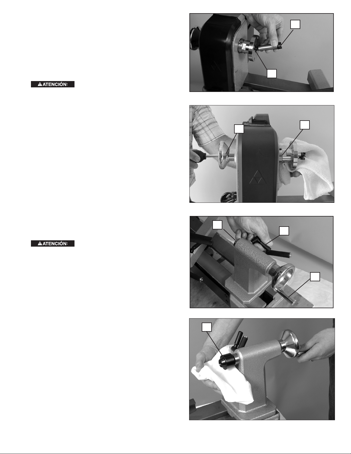
COLOCACIÓN DEL CENTRO DE DIENTES RECTOS
Introduzca el centro de dientes rectos en la pieza de
trabajo con un mazo blando. Luego encaje el centro de
dientes rectos (G) Fig.6 en el oricio del eje del cabezal
(N) con rmeza.
NOTA: No es necesario que quite la placa frontal para
colocar el centro de dientes rectos.
G
K
EXTRACCIÓN DEL CENTRO DE DIENTES RECTOS
Para reducir el riesgo de lesiones,
al extraer los centros, utilice un paño suave para
protegerse del borde loso.
Introduzca la barra de extracción (H) Fig.7 en el oricio
del eje (tal como se muestra en la Fig.7) y golpee con
rmeza el centro de dientes rectos (G) para quitarlo. De
ser necesario, golpee la barra de extracción con rmeza
con un mazo blando.
NOTA: Para evitar dañar el centro de dientes rectos,
asegúrese de sujetarlo mientras lo golpea para quitarlo.
COLOCACIÓN DEL CENTRO GIRATORIO
Aoje el tornillo de bloqueo del eje hueco del cabezal
móvil (O) Fig.8. Gire la manivela (P) del cabezal móvil
tres vueltas completas en sentido de las agujas del reloj
para mover hacia adelante el eje hueco (Q). Luego,
coloque el centro giratorio (F) Fig.9 en el eje hueco de
manera que quede rme. El tornillo de bloqueo del eje
hueco del cabezal móvil (O) Fig.8 se ajustará luego de
que monte la pieza de trabajo.
EXTRACCIÓN DEL CENTRO GIRATORIO
Para reducir el riesgo de lesiones,
al extraer los centros, utilice un paño suave para
protegerse del borde loso.
Para expulsar el centro giratorio (F) Fig.9, gire la
manivela (P) Fig.8 del cabezal móvil en sentido contrario
a las agujas del reloj para retraer el eje hueco. A medida
que el eje hueco se retrae, el centro giratorio hace
contacto con una clavija interna de expulsión. Cuando
esto ocurra, sentirá que se le hace más difícil girar la
manivela. Si sigue dando vueltas luego de pasar este
punto, el centro giratorio se aflojará para que pueda
quitarlo con facilidad.
N
Fig. 6
H
Fig. 7
G
Q
O
P
Fig. 8
F
43
Fig. 9
Page 44

CABEZAL MÓVIL
Para reducir el riesgo de lesiones,
apriete bien todos los tornillos y las palancas
cuando ajuste cualquier parte del torno.
AJUSTE DEL CABEZAL MÓVIL
Para ajustar la posición del cabezal móvil (A), aoje la
palanca de bloqueo (R) del cabezal móvil levantándola
para trabarla en su lugar. Deslice el cabezal móvil (A)
por la bancada Fig.11 hasta la posición deseada. Ajuste
la palanca de bloqueo (R) Fig. 10 del cabezal móvil
presionando hacia abajo.
Para reducir el riesgo de lesiones,
p
ara evitar lesiones, no coloque el borde del cabezal
móvil (S) Fig.11 de modo que sobrepase el borde de
la bancada del torno (T).
EXTRACCIÓN DEL CABEZAL MÓVIL
Para quitar el cabezal móvil (A) Fig.10, destrabe la
palanca de bloqueo (R) del cabezal móvil y deslícelo
hasta quitarlo del extremo de la bancada del torno.
BLOQUEO DEL EJE HUECO
El tornillo de bloqueo del eje hueco (O) Fig.12 ja el eje
hueco (Q) en su lugar cuando se utiliza con el centro
giratorio suministrado u otros accesorios del torno.
MANIVELA DEL CABEZAL MÓVIL
La manivela (P) del cabezal móvil mueve el eje hueco
(Q) hacia adelante y hacia atrás.
SOPORTE DE LA HERRAMIENTA
Para reducir el riesgo de lesiones,
a
priete bien todos los tornillos y las palancas
cuando ajuste cualquier parte del torno.
R
A
Fig. 10
A
S
Fig. 11
Q
O
T
Para ajustar la base del soporte de la herramienta (U)
Fig.13, aoje su palanca de bloqueo (V) y ajuste. La
base del soporte de la herramienta puede colocarse
de lado a lado, hacia adelante y hacia atrás, o puede
rotarse según se lo desee. Una vez que esté en su lugar,
trabe bien la base con la palanca (V).
Para ajustar el soporte de la herramienta (D), aoje su
tornillo de bloqueo (W). El soporte de la herramienta
puede colocarse en la posición que se desee. Una
vez que esté en su lugar, trabe bien el soporte de la
herramienta con la palanca (V).
NOTA: De ser necesario, puede ajustar el mango con
tornillo de bloqueo (W) y resorte hasta una posición más
conveniente al tirar del mango hacia afuera.
CAMBIO DE LAS VELOCIDADES DEL
TORNO
Para reducir el riesgo de lesiones,
no utilice el torno con la puerta de la cubierta de la
polea abierta.
Para el torno46-455, la velocidad está determinada
por uno de cinco pasos de poleas (consulte la sección
Cambio De Poleas a continuación). Las seis poleas
con el torno 46-455proporcionan seis velocidades
diferentes: 500, 950, 1 550, 2 700 y4 000RPM.
P
Fig. 12
D
W
V
U
Fig. 13
44
Page 45

El torno 46-460 está equipado con un control
electrónico de velocidad variable. Cambiar entre las
tres poleas (consulte la sección Cambio De Poleas
a continuación) determina el rango de velocidades
del torno, y una perilla de control aumenta o reduce
la velocidad dentro de ese rango. Las tres poleas
proporcionan tres rangos de velocidad: 250a750RPM,
600a1.800RPM y1.350a4.000RPM.
CAMBIO DE POLEAS (46-455y46-460)
Para reducir el riesgo de lesiones,
no utilice el torno con la puerta de la cubierta de la
polea abierta.
Para mover la correa entre las poleas:
1. Levante la cubierta de la polea (X), Fig. 14.
2. Baje la palanca tensora de la correa (Y) Fig.15 para
liberar la tensión de la correa.
3. Abra la puerta lateral inferior (AA) Fig.16 y mueva
la correa hasta el paso deseado de la polea y
de acuerdo con la tabla de velocidades que se
encuentra en la parte interna de la cubierta de la
polea (X) Fig.14. NOTA: Asegúrese de que las
ranuras en la parte interna de la correa (BB) Fig.17
se encajen completamente en las ranuras (CC) de
ambas poleas y que la correa no sobresalga del
borde de la polea.
4. Levante la palanca tensora de la correa (Y) Fig. 15
hasta que se encaje en su lugar.
5. Cierre bien la puerta lateral inferior (AA) Fig.16 y la
cubierta de la polea (X) Fig. 14.
Para ajustar la tensión de la correa:
X
Fig. 14
Y
Fig. 15
VELOCIDADES RECOMENDADAS PARA EL TORNO
MEDIANO
Las siguientes guías son aproximadas
y deben reducirse si la pieza de trabajo que está
utilizando no está equilibrada. Estas velocidades son
solo para piezas de grano lateral. Reduzca la velocidad y
tenga especial cuidado al cortar el grano grueso.
VELOCIDADES RECOMENDADAS (RPMs)
Desbaste Acabado
Diameter
de trabajo
Under 51 mm
(2")
51 mm to 107 mm
(2" to 4")
107 mm to 152 mm
(4" to 6")
152 mm to 203 mm
(6" to 8")
203 mm to 254 mm
(8" to 10")
254 mm to 305 mm
(10" to 12")
Bajo Alto Bajo Alto
950 1500 1900 3000
500 750 1500 2300
500 750 1500 2300
250 500 900 1500
250 500 900 1500
250 500 900 1500
CC
AA
Fig. 16
BB
Fig. 18
Fig. 17
45
Page 46

NOTA: La tensión de la correa se establece previamente
en la fábrica y sólo requiere ajustes si la correa se estira
con el tiempo o si se la cambia.
1. Abra la puerta de la polea (X) Fig.14 y la puerta
lateral (AA), Fig. 16.
2. Baje la palanca tensora de la correa (Y) Fig.15 para
liberar la tensión de la correa. No la trabe debajo de
la cha (Z).
3. Gire la ruedecilla (DD) Fig. 19 en sentido de las
agujas del reloj para aumentar la tensión o en
sentido contrario a las agujas del reloj para reducir la
tensión.
NOTA: Una correa con la tensión correcta se desviará
aproximadamente6,4 mm (1/4 pulg.) con una presión
moderada del dedo.
4. Levante la palanca (Y) Fig.15 y encájela en su lugar.
5. Cierre bien la puerta lateral inferior (AA) Fig.16 y la
cubierta de la polea (X) Fig.14.
CONTROL ELECTRÓNICO DE VELOCIDAD
VARIABLE (46-460ÚNICAMENTE)
Una vez que elija un rango de velocidades (tal como se
describe arriba en la sección Cambio De Poleas), utilice
la perilla de control de velocidad (EE) Fig.20 para variar
la velocidad dentro de ese rango. Si se ubica frente al
torno, gire la perilla hacia adelante (hacia usted) para
aumentar la velocidad, y hacia atrás (o alejándose de
usted) para reducir la velocidad.
DD
Fig. 19
EE
Fig. 20
HH
Para reducir el riesgo de lesiones,
s
iempre coloque la perilla de control de velocidad
en la conguración más baja antes de encender el
torno. Nunca comience a trabajar en una pieza a
velocidad máxima.
CLAVIJA INDICADORA
El torno incluye una clavija indicadora (FF) Fig.21. La
clavija permite trabar el eje (GG) en24 posiciones (tal
como está marcado en la rueda indicadora (HH)) para
usarlo en diferentes aplicaciones. Para usarla:
1. Gire la rueda indicadora (HH) de modo que el eje
(GG) esté en la posición deseada.
2. Retire un poco la clavija indicadora (FF) de la ranura
de retención.
3. Gire la clavija indicadora90grados de modo que el
pasador (II) se alinee con la cavidad, tal como se
muestra en la Fig. 21a.
4. Libere la clavija indicadora (FF) de modo que se
encaje en la rueda indicadora numerada (HH)
Fig.21 y trabe el eje (GG) en su lugar.
No encienda el torno con la clavija
indicadora encajada. Si lo hace, el torno podría dañarse.
No utilice la clavija indicadora (FF)
para trabar el eje cuando quite la placa frontal, ya que
esto puede dañar la clavija. Para quitar la placa frontal,
siga las instrucciones en la sección Extracción De La
Placa Frontal.
FF
GG
Fig. 21
II
FF
Fig. 21a
46
Page 47

ENCENDIDO Y APAGADO DEL TORNO
Para reducir el riesgo de lesiones,
segúrese de que el interruptor esté en la posición
de apagado "OFF" antes de enchufar el cable en
el tomacorriente. No toque las patas de metal del
enchufe al enchufar o desenchufar el cable.
Para encender el torno, coloque la paleta del interruptor
(JJ) Fig.22 en la posición de encendido "ON", es decir,
hacia arriba. Para apagar el torno, coloque la paleta del
interruptor en la posición de apagado "OFF", es decir,
hacia abajo.
JJ
BLOQUEO DEL INTERRUPTOR EN LA
POSICIÓN DE APAGADO ("OFF")
Para reducir el riesgo de lesiones,e
el caso de un corte eléctrico (por ejemplo por un
interruptor o fusible quemado) bloquee siempre el
interruptor en la posición de apagado ("OFF") hasta
que se restablezca la energía principal.
IMPORTANTE: Cuando no utilice la máquina, el
interruptor debe bloquearse en la posición de apagado
("OFF") con un candado (KK) Fig. 23 con argolla
de6,4mm (1/4 pulg.) de diámetro, para evitar el uso no
autorizado de la unidad.
n
PROTECTOR DE SOBRECARGA DEL
MOTOR
La herramienta cuenta con un interruptor automático que
puede reiniciarse manualmente. Si la herramienta se
sobrecarga o se para demasiado tiempo, el interruptor
automático se activará y apagará la herramienta.
Para volver a encenderla:
1. Ubique el interruptor de encendido/apagado ("ON/
OFF") en la posición de apagado ("OFF").
2. Deje que el motor se enfríe entre3y5minutos.
3. Presione el botón de reinicio (LL), Fig. 24.
4. Vuelva a utilizar la máquina normalmente.
Fig. 22
KK
Fig. 23
LL
47
Fig. 24
Page 48

UTILIZAR LA MAQUINA
Para reducir el riesgo de lesiones
• Apriete bien todos los tornillos y las palancas cuando
ajuste cualquier parte del torno. Además, antes
de encender el torno, asegúrese de que todos los
accesorios estén bien ajustados.
• Cuando utilice la placa frontal incluida de76 mm
(3 pulg.) (B) Fig. 25, no monte piezas de más
de152 mm (6 pulg.) de diámetro y hasta152 mm (6
pulg.) de largo. Para montar piezas más grandes,
asegúrese de usar una placa frontal de tamaño
adecuado.
• Mantenga las manos alejadas de la pieza de trabajo
cuando esté girando.
• Utilice sólo los accesorios recomendados para este
producto y siga todas las instrucciones que se incluyen
con los accesorios.
• Asegúrese de que el cable no esté en el camino de
la pieza de trabajo giratoria ni las piezas giratorias del
torno.
• No toque la punta de la herramienta de torneado
inmediatamente después de haberla utilizado en la
pieza de trabajo, ya que puede estar caliente.
• No aplique agua ni otros refrigerantes al torno cuando
esté girando.
• No tornee materiales que no sean de madera en
este torno. Este torno se diseñó para tornear madera
exclusivamente.
• Antes de utilizar el torno, asegúrese de que las llaves
del portabrocas no estén en el portabrocas.
• PARA EL TORNO MIDI DELTA® MODELO 46-460
ÚNICAMENTE: Asegúrese de utilizar sólo accesorios
equipados con un tornillo de bloqueo para girar el torno
en reversa. Además, no cambie las direcciones de
torneado hasta que la pieza de trabajo se detenga por
completo.
MONTAJE DE LA PIEZA DE TRABAJO
NOTA: Cuando monte una pieza de trabajo, primero
introduzca el centro de dientes rectos en la pieza de trabajo
golpeándolo con un mazo blando, antes de instalarlo en el
cabezal.
Se muestra el montaje de una taza típica en la Fig. 25.
Las piezas de trabajo pueden montarse en la placa frontal
a través de los cuatro orificios de la misma usando tornillos
apropiados para el tipo de madera que desea tornearse.
El montaje de otro tipo de pieza de trabajo, donde la pieza de trabajo está fija entre el centro de dientes rectos y el giratorio,
se muestra en la Fig. 26. A continuación se detallan algunos consejos sobre este montaje:
1. Para montar la pieza de trabajo, mueva el cabezal móvil hasta una distancia aproximada de25 mm (1 pulg.) o38mm
(1-1/2 pulg.) del extremo de la pieza de trabajo y trábelo en esta posición.
2. Mueva el centro giratorio (E) girando la manivela del cabezal móvil (P) Fig.27 hasta que el centro fijo haga contacto con la
pieza de trabajo.
3. No apoye la pieza de trabajo solamente sobre la clavija central. Incruste siempre el borde del centro fijo al menos3,2mm
(1/8 pulg.) en la pieza de trabajo.
:
B
Fig. 25
Fig. 26
E
Fig. 27
O
P
48
Page 49

4. Trabe el tornillo de bloqueo del eje hueco (O).
TORNEADO EN REVERSA (46460ÚNICAMENTE)
PARA EL TORNO MIDI DELTA®
MODELO 46-460 ÚNICAMENTE:
riesgo de lesiones,
accesorios equipados con un tornillo de bloqueo
para girar el torno en reversa. Además, no cambie
las direcciones de torneado hasta que la pieza de
trabajo se detenga por completo.
la pieza de trabajo al tornear en reversa. En caso
de atascamiento, detenga el torno y verifique que el
portabrocas o la placa frontal estén bien colocados
y que ambos tornillos de sujeción estén ajustados
antes de continuar.
El torno viene listo para tornear hacia adelante (hacia abajo y hacia el usuario) para las aplicaciones típicas de
torneado de madera. Sin embargo, algunas aplicaciones requieren que el torno funcione en reversa (hacia arriba y
alejándose del usuario). El46-460puede tornear en reversa. Para hacer esto:
1. Asegúrese de que el interruptor de encendido del torno esté apagado y que el eje no esté girando.
2. Deslice el interruptor (MM) Fig.28 a la posición "FWD" (avance) o "REV" (reversa), según la rotación que desee
obtener.
NOTA: El interruptor de avance/reversa (marcado "FWD"/ "REV") emplea una función de bloqueo para evitar que se
cambie de dirección cuando el interruptor de encendido/apagado (ON/OFF) está en la posición de encendido "ON", es
decir, hacia arriba.
3. Si se utiliza una placa frontal, un portabrocas u otro accesorio que deba enroscarse en el cabezal del eje, asegúrese
de que el tornillo de sujeción esté bien ajustado antes de utilizar la máquina en reversa.
asegúrese de utilizar sólo
Debe tener cuidado de no atascar
Para reducir el
MM
Fig. 28
Para obtener asistencia para su máquina, visite nuestro sitio Web en www.DeltaMachinery.com para tener acceso a una
lista de centros de servicio o llame a la línea de ayuda de DELTA® Power Equipment Corporation al 1-800-223-7278.
Para reducir el riesgo de lesiones personales graves, apague la herramienta y desconéctela de la fuente de alimentación
antes de instalar y retirar accesorios, ajustar o cambiar configuraciones o realizar reparaciones.
MANTENGA LA MÁQUINA LIMPIA
Para reducir el riesgo de lesiones,
oídos y vías respiratorias cuando use aire comprimido.
utilice equipo de seguridad certificado para proteger sus ojos,
FALLA EN EL ENCENDIDO
LUBRICACIÓN Y PROTECCIÓN CONTRA ÓXIDO
Para limpiar el óxido de las mesas de hierro fundido, necesitará los siguientes materiales: una almohadilla para fregar
de tamaño mediano, una lata de lubricante en aerosol y una lata de desgrasador. Aplique el lubricante en aerosol y pula
la supercie de la mesa con la almohadilla para fregar. Desgrase la mesa y luego aplique el producto protector como se
muestra más arriba.
49
Page 50

MANTENIMIENTO PERIÓDICO
• Verifique que todos sujetadores estén ajustados correctamente.
• Verifique la tensión de la correa y ajústela de ser necesario. Consulte la sección Cambio De Poleas para obtener
instrucciones.
• Inspeccione la correa en busca de daños o desgaste y cámbiela de ser necesario. Para conocer las instrucciones de
cambio de la correa, consulte la siguiente sección.
• Revise ambos tornillos de sujeción de la placa frontal para asegurarse de que el borde del centro jo esté alado y liso.
Reemplace de ser necesario.
CAMBIO DE LA CORREA
1. Levante la cubierta de la polea (X), Fig. 29.
2. Baje la palanca tensora de la correa (Y) Fig.30 para liberar la tensión de la correa.
3. Quite el centro de dientes rectos (G) Fig.30, si está colocado.
4. Afloje dos tornillos de sujeción (NN) Fig.31 en el volante del eje (OO) Fig.31 al menos2ó3vueltas para evitar
dañar las roscas durante la extracción.
5. Encaje la clavija indicadora (FF) Fig.31 y retire el volante del eje (OO). (NOTA: Las roscas están a la izquierda.
Gire el volante en sentido de las agujas del reloj para aflojarlo y quitarlo.)
6. Quite el resorte ondulado (PP), Fig. 32.
X
G
Y
Fig. 29
Fig. 30
PP
OO
NN
FF
QQ
Fig. 31
Fig. 32
Fig. 32
RR
SS
Fig. 34
50
Page 51

7. Afloje el tornillo de sujeción de la polea del eje (QQ)
Fig.33 con la llave hexagonal incluida.
8. Sujete la polea del eje (RR) Fig.34 con una mano y
deslice el eje (SS) hacia afuera con la otra mano en
dirección al cabezal móvil.
9. Quite la correa y cámbiela.
10. Coloque la correa nueva sobre la polea del eje y
asegúrese de que las ranuras de la correa estén
alineadas con las ranuras de la polea.
11. Coloque la polea del eje (RR) dentro del cabezal
(tal como se muestra en la Fig.35) y sosténgala
mientras introduce el eje (SS) a través del cabezal y
la polea. Fíjese de alinear la llave del eje (TT) con la
ranura de la polea (no se muestra).
12. Asegúrese de que la polea esté bien apoyada
contra el reborde del eje (UU).
13. Ajuste bien el tornillo de sujeción de la polea (QQ)
Fig.33.
14. Vuelva a instalar el resorte ondulado (PP) Fig. 32
y el volante (OO) Fig.31. El volante se ajusta en
sentido contrario a las agujas del reloj. Ajuste el
volante completamente y luego aflójelo 1/4de
vuelta. AVISO: NO LO AJUSTE EN EXCESO. Si lo
hace, los rodamientos podrían dañarse.
15. Ajuste bien los dos tornillos de sujeción del volante
(NN) Fig.31. Con la correa colgando suelta, gire el
eje para asegurarse de que rote libremente.
16. Levante la palanca tensora de la correa (Y) Fig. 30 y
encájela en su lugar.
17. Verifique la tensión de la correa y ajústela de
ser necesario. (Consulte la sección Cambio De
Poleas.)
18. Cierre bien la cubierta de la polea (X) Fig. 29 y la
puerta lateral (AA) Fig.16.
19. Desencaje la clavija indicadora (FF) Fig.31 si se la
colocó para quitar el volante del eje (OO).
Para reducir el riesgo de lesiones,
no utilice el torno con la puerta de la cubierta de la
polea abierta.
No encienda el torno con la clavija
indicadora encajada. Si lo hace, el torno podría dañarse.
RR
TT
UU
SS
Fig. 35
51
Page 52

SERVICIO
PIEZAS DE REPUESTO
Utilice sólo piezas de repuesto idénticas. Para obtener una lista de piezas o para solicitar piezas, visite nuestro sitio web en
www.DeltaMachinery.com/service. También puede solicitar piezas en nuestro centro más cercano, o llamando a nuestro Centro
de atención al cliente al 1-800-223-7278 para obtener asistencia personalizada de nuestros técnicos capacitados.
REEMPLAZO GRATUITO DE LAS ETIQUETAS DE ADVERTENCIA
Si las etiquetas de advertencia se tornan eligibles o se pierden, llame al 1-800-223-7278 para reemplazarlas sin costo alguno.
MANTENIMIENTO Y REPARACIONES
Con el paso del tiempo, todas las herramientas de calidad requieren mantenimiento o reemplazo de las piezas. Para obtener
información acerca de DELTA® Power Equipment Corporation, sus sucursales propias o un Centro de mantenimiento con
garantía autorizado, visite nuestro sitio web en www.DeltaMachinery.com o llame a nuestro Centro de atención al cliente al
1-800-223-7278. Todas las reparaciones realizadas por nuestros centros de mantenimiento están completamente garantizadas
en relación con los materiales defectuosos y la mano de obra. No podemos otorgar garantías en relación con las reparaciones
ni los intentos de reparación de otras personas.
También puede escribirnos solicitando información a DELTA® Power Equipment Corporation, 99 Roush Street, Anderson,
South Carolina 29625 - Mantenimiento de productos. Asegúrese de incluir toda la información mencionada en la placa de la
herramienta (número de modelo, tipo, número de serie, etc.)
ACCESORIOS
Puesto que los accesorios con excepción de ésos ofrecidos por DELTA® no se han probado
con este producto, el uso de tales accesorios podría ser peligroso. Para la operación más segura, solamente el
DELTA® recomendó los accesorios se debe utilizar con este producto.
Una línea completa de accesorios está disponible de su surtidor de DELTA®, centros de servicio de la fábrica de
DELTA®, y estaciones autorizadas DELTA®. Visite por favor nuestro Web site www.DeltaMachinery.com para un
catálogo o para el nombre de su surtidor más cercano.
52
Page 53

PÓLIZA DE GARANTÍA
IDENTIFICACIÓN DELPRODUCTO:
Sello o firma del Distribuidor.Nombre del producto: __________________________ Mod./Cat.:
________________________Marca:__________________________Núm. de serie:________________________
(Datos para ser llenados por el distribuidor)Fecha de compra y/o entrega del producto: _______
________________________________Nombre y domicilio del distribuidor donde se adquirió el
producto:__________________________________________________________________________
Este producto está garantizado por tres años de garantía limitada a partir de la fecha de entrega, contra cualquier defecto
en su funcionamiento, así como en materiales y mano de obra empleados para su fabricación. Nuestra garantía incluye
la reparación o reposición del producto y/o componentes sin cargo alguno para el cliente, incluyendo mano de obra, así
como los gastos de transportación razonablemente erogados derivados del cumplimiento de este certicado. Para hacer
efectiva esta garantía deberá presentar su herramienta y esta póliza sellada por el establecimiento comercial donde se
adquirió el producto, de no contar con ésta, bastará la factura de compra.
EXCEPCIONES
Esta garantía no será válida en los siguientes casos:
• Cuando el producto se hubiese utilizado en condiciones distintas a las normales;
• Cuando el producto no hubiese sido operado de acuerdo con el instructivo de uso que se acompaña;
• Cuando el producto hubiese sido alterado o reparado por personas distintas a las enlistadas al nal de este certicado.
Anexo encontrará una relación de sucursales de servicio de fábrica, centros de servicio autorizados y franquiciados en la
República Mexicana, donde podrá hacer efectiva su garantía yadquirir partes, refacciones y accesorios originales.
53
Page 54

GARANTIA
Para registrar la herramienta para obtener el mantenimiento cubierto por la garantía de la herramienta, visite nuestro sitio web
en www.DeltaMachinery.com.
Garantía limitada de cinco años para productos nuevos
DELTA® reparará o reemplazará, a expensas y opción propias, cualquier máquina nueva, pieza de máquina nueva o accesorio de máquina nuevo
DELTA® que durante el uso normal haya presentado defectos de fabricación o de material, siempre que el DELTA® devuelva el producto con el
transporte prepagado a un centro de servicio de fábrica DELTA® o una estación de servicio autorizado DELTA®, con un comprobante de compra
del producto, dentro del plazo de cinco años y dé a DELTA® una oportunidad razonable de verificar el supuesto defecto mediante la realización de
una inspección. Para todos los productos DELTA® reacondicionados, el período de garantía es de 180 días. DELTA® no será responsable de ningún
defecto alegado que haya resultado del desgaste normal, uso indebido, abuso o reparación o alteración realizada o autorizada específicamente
por alguien que no sea un centro de servicio autorizado DELTA® o un representante autorizado DELTA®. DELTA® no será responsable en
ninguna circunstancia de los daños incidentales o emergentes que se produzcan como resultado de productos defectuosos. Algunos estados
no permiten la exclusión o limitación de los daños incidentales o resultantes, por lo que la limitación o exclusión anterior puede no aplicarse a
usted. Esta garantía es la única garantía de DELTA® y establece el recurso exclusivo del cliente en lo que respecta a los productos defectuosos;
DELTA® rechaza expresamente todas las demás garantías, expresas o implícitas, tanto de comerciabilidad como de idoneidad para un propósito
o de cualquier otro tipo. Para mayores detalles sobre la cobertura de la garantía e información acerca de reparaciones realizadas bajo garantía,
visítenos en www.DeltaMachinery.com o dirígase al centro de servicio más cercano 1-800-223-7278. Esta garantía no aplica a accesorios o a daños
causados por reparaciones realizadas o intentadas por terceros. Esta garantía le otorga derechos legales específicos, además de los cuales
puede tener otros dependiendo del estado o provincia en que se encuentre.
AMÉRICA LATINA: Esta garantía no se aplica a los productos que se venden en América Latina. Para los productos que se venden en América
Latina, debe consultar la información de la garantía especíca del país que viene en el empaque, llamar a la compañía local o visitar el sitio
Web a n de obtener esa información.
Especicaciones
46-460 46-455
Tensión de alimentación: 120 V AC~ 120 V AC~
Consumo de corriente: 8A 5.3A
Frecuencia de operación: 60 Hz 60 Hz
Rotación sin carga: 3 000 RPM 1 790 RPM
54
Page 55

NOTES/NOTAS
55
Page 56

DELTA® Power Equipment Corporation
99 Roush Street
Anderson, South Carolina 29625
(800) 223-7278
www.DeltaMachinery.com
Copyright © 2011
DELTA® Power Equipment Corporation
A29190 - 2-21-12
REVISED: 12-02-14
 Loading...