

Page 1

INSTRUCTION MANUAL
Wood Turning Duplicator
(Model 46-408)
PART NO. 904419 - 02-05-02
Copyright © 2001 Delta Machinery
To learn more about DELTA MACHINERY
visit our website at: www.deltamachinery.com.
For Parts, Service, Warranty or other Assistance,
please call
1-800-223-7278 (In Canada call 1-800-463-3582).
Page 2
2
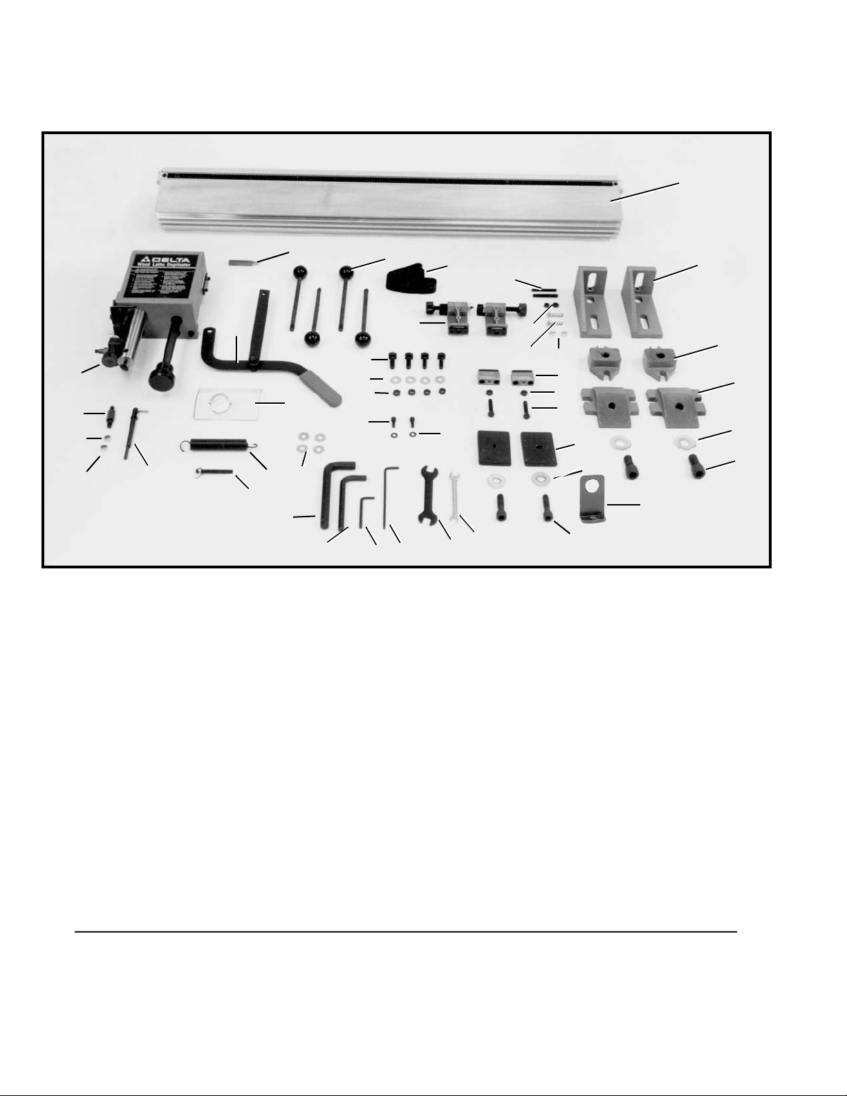
UNPACKING
The accessory 46-408 Wood Turning Duplicator is shipped in one container. Carefully unpack and separate
all loose items and proceed with assembly instructions. Fig. 2 illustrates the components of the duplicator.
Refer to the parts description for assembly to your particular wood lathe.
Fig. 2
ASSEMBLY INSTRUCTIONS
The 46-408 Wood Turning Duplicator is designed for use with Delta 12", 14", and 16" Wood Lathes. Before
assembly, make certain the wood lathe is disconnected from the power source.
1. Duplicator Rail
2. Mounting Brackets (2)
3. Brackets for 12” Wood Lathes (2)
4. Brackets for 16” Top Turn Wood Lathes (2)
5. 16mm x 41mm Washers (2)
6. M16 x 35mm Hex Socket Head Screws (2)
7. M12 x 45mm Hex Socket Head Screws (2)
8. M12 Flat Washers (2)
9. Plates (2)
10. M8 x 40mm Hex Head Screws (2)
11. M8 Hex Nuts (2)
12. Pattern Support Brackets (2)
13. M6 Hex Nut for DL-40 Wood Lathe (2)
14. M6 x 30mm Hex Head Screw for DL-40 Wood Lathes (2)
15. M8 Hex Nuts for Top Turn and 12” Wood Lathes (2)
16. M8 x 55mm Hex Socket Set Screw for Top Turn and 12” Wood Lathes (2)
17. Brackets (2)
18. Belt
19. Handles (4)
20. Lever
21. 3/8” Duplicator Cutting Tool
22. Dust Guard
23. Spring
24. Stud
25. M4.5 x 25mm Follower Arm
26. Stud
27. M8.4 Flat Washers (2)
28. M8 Hex Nut
29. Carriage
30. 14mm Hex Wrench
31. 10mm Hex Wrench
32. 5mm Hex Wrench
33. 4mm Hex Wrench
34. 13 x 14mm Wrench
35. 8 x 10mm Wrench
36. T-Bolts (4)
37. 10mm Flat Washers (4)
38. M10 Hex Nuts (4)
39. M6 x 10mm Hex Socket Head Screws (2)
40. M6.4 Flat Washers (2)
41. M8.4 Flat Washers (4)
42. Bracket for 46-745 & 46-715 Beds (2)
* M8 Wing Nut
* 4mm Ball Socket Hex Wrench
* NOT SHOWN
1
2
3
4
5
6
7
8
9
10
11
12
17
18
16
15
13
14
19
21
20
22
29
26
27
28
25
24
23
41
36
37
38
39
40
35
34
30
31
32
33
42
Page 3
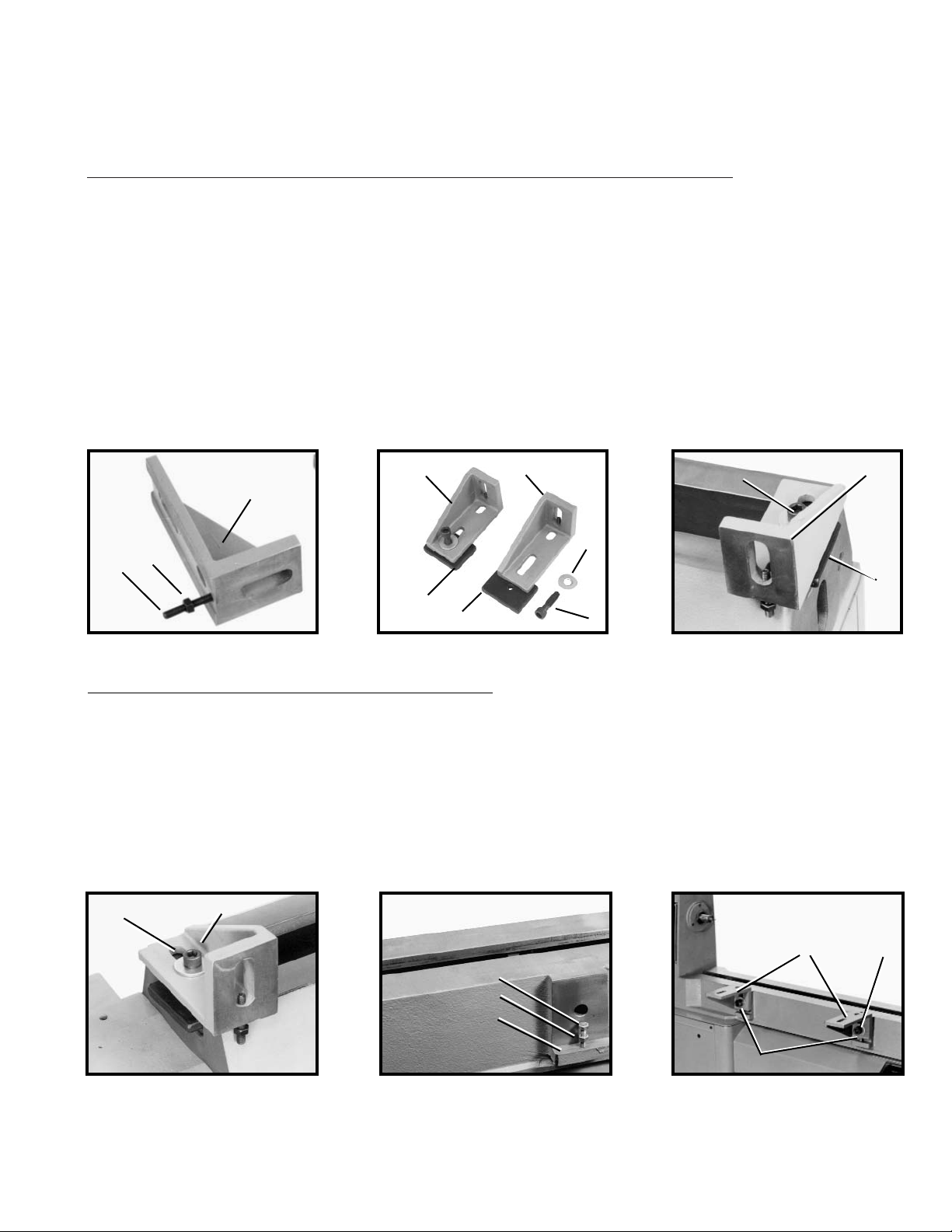
ATTACHING MOUNTING BRACKETS
For Delta Models 46-860 16", 46-745 16" & 46-715 14" Wood Lathes Only
1. Thread M8 Hex Nut (A) Fig. 3 on M8 X 55mm Socket Set screw (B).
NOTE: Do not install (A) or (B) Fig. 3 when using the model 46-715 or the model 46-745. Discard the nuts and set aside
the screws for further use. (See”ATTACHING DUPLICATOR TO WOOD LATHE” in this document).
2. Thread the socket set screw (B) Fig. 3 with hex nut (A) into the tapped hole in both mounting brackets (C).
NOTE: To make installation easier, adjust the screws so they are equal in length, then tighten hex nuts (A) against the
bottom of mounting brackets (C).
3. Position clamping plate (D) Fig. 4 under mounting brackets (C) and fasten with two M12 x 45mm hex
socket head screws (E) and
16mm x 41mm
flat washers (F). Tighten screws just enough to hold assembly together.
Remove tailstock from the machine.
4. Insert clamping plate (C) Fig. 5 of mounting bracket assembly (D) into channel on tailstock end of lathe bed. NOTE:
Loosely tighten hardware (E).
5. Slide the remaining mounting bracket assembly (C) Fig. 6 onto the lathe bed at the headstock end of the wood
lathe. Move it to about one inch from the end of the lathe bed. NOTE: Loosely tighten hardware (E).
3
Fig. 3 Fig. 4
Fig. 5
Fig. 6
C
B
A
D
D
E
F
C
C
E
C
D
E
C
B
A
C
Fig. 7
Fig. 8
D
E
B
For Delta Model DL-40 16” W
ood Lathes Only
1. Thread M6 Hex Nut, one of which is shown at (A) Fig. 7 on M6 x 30 hex head screw (B) and thread the hex head screw
(B) into mounting ledge (C) at the front of the lathe bed. Similarly, thread the remaining M6 x 30 hex head screw with locknut to the mounting ledge on the other end of the lathe bed in the same manner. NOTE: To make the installation easier,
adjust the two hex head screws (B) Fig. 7 so the tops of screws (B) are equal to each other in length. Tighten hex nuts (A)
Fig. 7 against ledge (C).
2. Attach the two mounting brackets (D) Fig. 8 to the front of the lathe bed, and fasten with two
M16 x 35mm hex socket head screws (E) and two flat washers (E). NOTE: Rest the bottom of mounting brackets (D)
on top of hex head screws (B).
Page 4
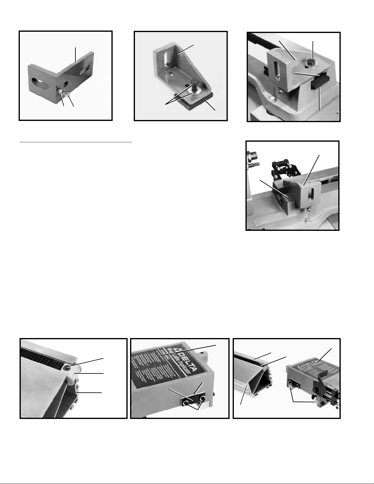
For Delta 12” Wood Lathes Only
1. Thread M8 hex nuts (A) Fig. 9 on M8 x 55mm hex socket set screws (B).
2. Thread set screws (B) Fig. 9 with hex nuts (A) into the two tapped holes in the
bottom of mounting brackets (D). NOTE: To make installation easier, adjust the two
set screws (B) so that tops of screws are equal in length, then tighten hex nuts (A)
against bottom of mounting brackets (D).
3. Position clamping plates (E) Fig. 10 under mounting brackets (D). Fasten
with M8 x 55mm socket head set screws (F) with
16mm x 41mm
flat washers (F).
Loosely tighten hardware (F) Fig. 10. Remove the tailstock from the machine.
4. Insert clamping plate (E) Fig. 11 of mounting bracket assembly (D) into
channel (G) on tailstock end of lathe bed. NOTE: Loosely-tighten mounting
hardware (F).
5. Slide the remaining mounting bracket assembly (D) Fig. 12 at the headstock
end of the wood lathe in the same manner. NOTE: Position the left side of
mounting bracket assembly (D) Fig. 12 so it is approximately 1" from the end of
the lathe bed (H). NOTE: Loosely tighten the mounting hardware.
4
Fig. 11
Fig. 12
Fig. 13 Fig. 14
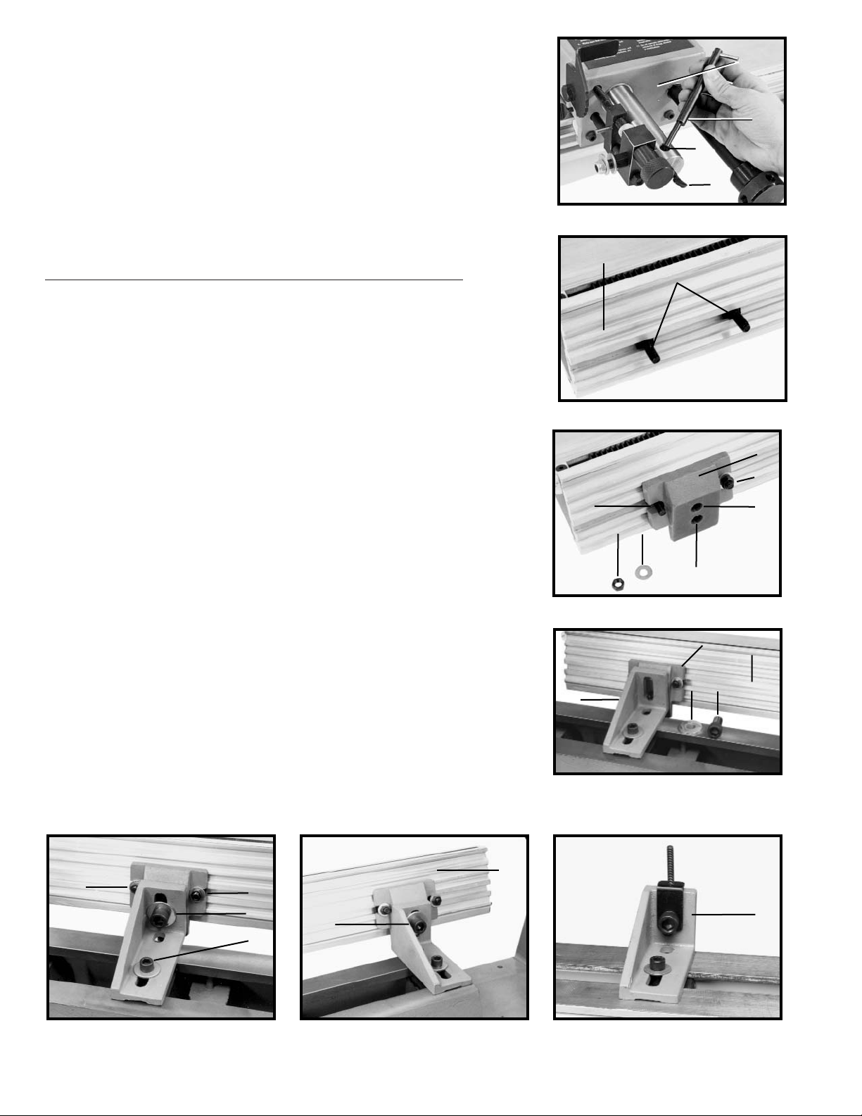
ATTACHING CARRIAGE TO DUPLICATOR RAIL
1. Loosen and remove screw (A) Fig. 13 and belt guide (B) from the RIGHT END of duplicator rail (C).
2. Loosen two screws (D) Fig. 14 and raise wiper (E) and retainer plate (F) to their highest position. Tighten two
screws (D). Repeat this procedure on the other side of carriage (G).
3. Slide carriage (G) Fig. 15 onto duplicator guide rail (C) by inserting two guides (H) into channels (J) and sliding
carriage (G) into gear rack (K). Replace belt guide and screw that were removed in STEP 1 to the right side of the dupli-
cator rail (C).
D
F
G
E
D
H
A
B
C
G
E
F
D
Fig. 9
Fig. 10
D
A
B
E
F
D
Fig. 15
J
K
C
G
H
Page 5
5
Fig. 16
Fig. 17
Fig. 18
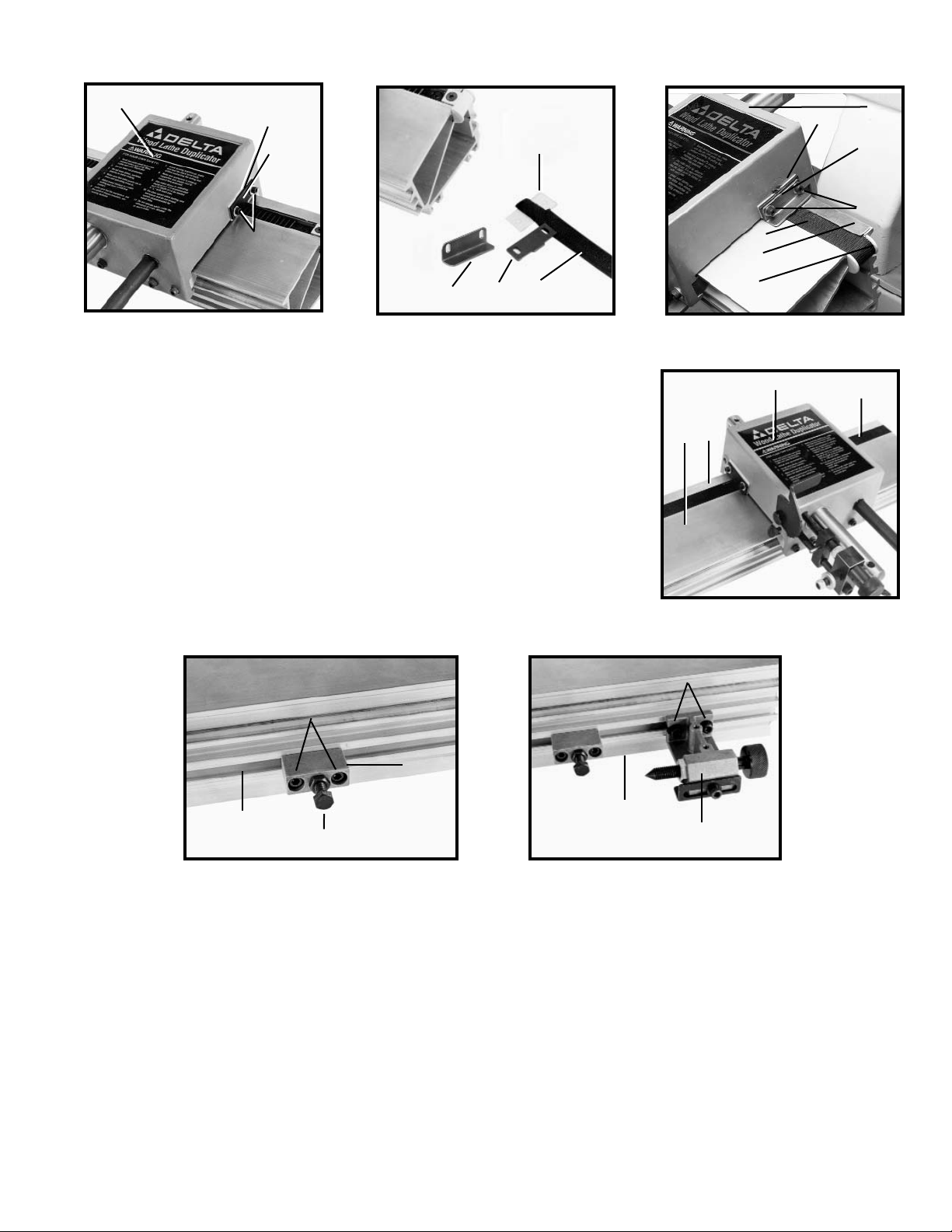
4. Remove the two screws and washers (D) Fig. 16, wiper, (E) and retainer
plate (F) from each side of the carriage (G).
5. Place one end of belt (L) Fig. 17 on wiper (E) and cover with retainer plate
(F) and angle bracket (F2). NOTE: Cut-out section of belt (L) must be positioned
with, or slightly below, right side of wiper (E).
6. Line up holes in wiper (E) Fig. 18, retainer plate (F), and angle bracket with
the two holes on the side of the carriage (G) and fasten the belt (L) to the carriage with the two hex socket head screws and flat washers (D) removed earlier.
7. Attach belt (L) Fig. 18 under the lip (M) of the duplicator rail and around the
guide (B). Pass belt (L) inside and through duplicator rail (C) Fig. 19 and out the
other end of the duplicator rail. IMPORTANT: Make certain belt is not twisted
inside duplicator rail.
8. Wrap the loose end of the belt (L) Fig. 19 around the guide on the left side
of the rail (C) and under the lip (M) of the guide rail. Fasten the belt (L) to the side
of the carriage (G) by repeating STEPS 5 and 6.
G
F
E
D
E
F
L
G
F
E
D
L
B
M
Fig. 19
C
L
M
G
Fig. 20
Fig. 21
ATTACHING PATTERN SUPPORT BRACKETS TO DUPLICATOR RAIL
1. Slide pattern support bracket (A) Fig. 20 into bottom channel of duplicator rail (B) and tighten two screws (C).
2. Thread a M8 x 40mm hex head screw (D) with M8 hex nut into face of pattern support bracket (A). Adjustments
will be made later.
3. Attach remaining pattern support bracket to opposite end of duplicator rail in the same manner.
ATTACHING PATTERN HOLDING BRACKETS TO DUPLICATOR RAIL
1. Slide pattern holding bracket (A) Fig. 21 into bottom channel of duplicator rail (B) and tighten two screws (C).
Adjustments will be made later.
2. Assemble remaining pattern holding bracket to the opposite end of duplicator rail in the same manner.
C
A
D
B
C
B
A
F2
Page 6
ATTACHING FOLLOWER ARM TO
CARRIAGE ASSEMBLY
Insert follower arm (A) Fig. 22 into hole in arm (B) of carriage assembly and
tighten thumb screw (C). NOTE: Pin (D) of follower arm (A) should point
toward right end of duplicator rail.
6
ATTACHING DUPLICATOR TO
WOOD LATHE
For Model 46-860, 46-715, and 46-745 Wood Lathes Only
.
1. Slide two T-bolts (G) Fig. 23 into channel located at the rear of duplicator guide rail (H).
2. Place mounting pad (J) Fig. 24 between two T-bolts (G) and slide T-bolts
inward into slots of mounting pad (J) and fasten with two M10 flat washers
(K) and M10 hex nuts (L). NOTE: Loosely tighten hardware.
NOTE: Use top hole of bracket (A) Fig. 24 for Model 46-715 14" lathe only.
Use the center hole (B) Fig. 24 for all 16" lathes.
3. Attach the remaining mounting pad to the other end of duplicator pad in
the same manner.
4. IMPORTANT: To prevent personal injury or damage to the duplica-
tor, use two or more people to mount the duplicator to the mounting
brackets.
5. While carefully supporting the duplicator rail (H) Fig. 25 at both ends,
slide the mounting pad (J) along the duplicator rail until the tapped hole in
mounting pad (J) lines up with slot in mounting bracket (C). Fasten with M16
x 35mm hex socket head screw (M) and
16mm x 41mm
flat washer (N). NOTE:
For 46-715 or 46-745, use bracket (A) Fig. 27B with M8 x 55mm socket
head set screw without washer.
6. Tighten two hex nuts (L) Fig. 26 and two hex socket head bolts (E) and
(M).
7. Mount duplicator assembly (H) Fig. 27A to mounting bracket (C) at the
other end of the lathe in the same manner. Tighten all mounting hardware.
Replace tailstock on the machine.
Fig. 22
Fig. 23
Fig. 24
Fig. 25
Fig. 26
Fig. 27A
Fig. 27B
C
B
A
D
A
B
G
K
L
G
H
C
J
H
N B
L
L
M
E
C
H
A
J
G
Page 7

7
For Delta Model DL-40 16” Wood Lathe Only
1. Insert two T-bolts (A) Fig. 28 into channel (B1) located on the left underside of duplicator rail (C).
2. Insert the two remaining T-bolts to the right underside of the duplicator rail (B2) in the same manner.
3. IMPORTANT: To prevent personal injury or damage to the duplicator, use two or more people to mount the
duplicator to the mounting brackets.
4. Carefully guide the duplicator rail (C) Fig. 29, so four T-bolts (A) fit into four slots (D) in mounting brackets. Fasten
duplicator rail (C) Fig. 29 to the mounting brackets using four M10 flat washers and M10 hex nuts (F).
5. Tighten four M10 hex nuts (F) Fig. 30 only enough to hold the
duplicator rail in place on the mounting brackets.
6. Slide duplicator rail (C) Fig. 31 to the left until edge of rail is
approximately 1" from right side (G) of headstock.
7. Tighten hardware (F) Fig. 30.
Fig. 28 Fig. 29
Fig. 30
Fig. 31
For Delta 12” Wood Lathes Only
1. Slide two T-bolts (A) Fig. 32 into channel (B) located at the rear of duplicator rail.
2. Place mounting pad (D) Fig. 33 between two T-bolts (A) and slide T-bolts inward in slots of mounting pad (D). Fasten
with two M10 flat washers and M10 hex nuts (E). NOTE: Loosely tighten hardware.
3. Attach remaining mounting pad (D) Fig. 34 to the other end of duplicator rail (C) in the same manner.
4. IMPORTANT: To prevent personal injury or damage to the duplicator, use two or more people mount the duplicator to
the mounting brackets.
Fig. 32 Fig. 33
Fig. 34
C
B1
A
C
B
A
D
F
A
D
F
F
F
G
C
B
A
A
E
D
E
C
D
B2
Page 8

ATTACHING HANDLE ASSEMBLY TO CARRIAGE
1. Loosen and remove hex nut (A) Fig. 38, two flat washers (B) and stud (C)
from handle assembly (D). IMPORTANT: Remove wing nut (E) to loosen one
end of spring (F).
2. Thread stud (C) with a flat washer (B) Fig. 39 (removed in STEP 1) to left
side of carriage assembly (E).
3. Loosen and remove hex nut (G) Fig. 39, and one flat washer (H) from stud
of carriage assembly (E).
4. Attach handle assembly (D) Fig. 40 on studs (C) and (K). Fasten with hex
nuts (A) and (G) and flat washers (B) and (H) (removed in STEPS 1 and 3).
5. Attach free end of tension spring (L) Fig. 41 through the hole in end of
threaded rod (M). Carefully apply tension to spring (L) and insert end of threaded rod (M) through hole in lip of handle assembly (D). Fasten with flat washer
and wing nut (E) (removed from handle assembly (D) in STEP 1). Correct spring
tension is determined by the operator and can be adjusted later.
ATTACHING HANDLES TO CARRIAGE SHAFT
1. Thread four handles (J) Fig. 42 into hub (K) of carriage shaft (L)
.
8
5. Support the duplicator at both ends while sliding mounting pad (D) Fig. 35 along the duplicator rail. Slide until the tapped hole
in mounting pad (D) lines up with the slot in mounting bracket (F), and fasten with M16 x 35mm hex socket head screw and flat
washer (G) using supplied 14mm hex wrench (H).
6. Tighten two hex nuts (one of which is shown at (E) Fig. 36, socket head bolt (G) and hex head bolt (J). Final adjustments
will be made later.
7. Mount the duplicator assembly (C) Fig. 37 to mounting bracket (F) on the other end of the lathe in the same manner.
IMPORTANT: Tighten all mounting hardware.
8. Replace tailstock.
Fig. 35 Fig. 36
Fig. 37
Fig. 38
Fig. 39
Fig. 40 Fig. 41
Fig. 42
H
G
D
F
E
G
J
C
F
D
A
F
E
B
C
B
C
E
G
H
C
A
B
D
K
G
H
L
K
M
D
G
J
L
K
Page 9

9
The carriage assembly was aligned at the factory. However, shipment handling may require a readjusment of the
carriage assembly. Carriage travel along the guide rail is critical to the proper alignment of the duplicator to the lathe
centers. Perform the following procedures and adjustments (if necessary) prior to the initial operation of the duplicator.
1. DISCONNECT THE MACHINE FROM THE POWER SOURCE AND TIGHTEN ALL DUPLICATOR MOUNTING BOLTS.
2. Grasp the carriage assembly (A) Fig. 44. Check for any unwanted play (movement) between the carriage assembly and rail. If
no play is present between the carriage assembly and rail, proceed with STEP 4.
3. If loose movement is detected in the carriage assembly (A) Fig. 44, determine which side of the carriage assembly needs
adjustment. Loosen two corresponding lock screws (B) Fig. 44, located at the rear of carriage assembly (A), and turn corresponding adjustment screw (C) clockwise. IMPORTANT: Turn the adjustment screw (C) only slightly. Check and readjust if nec-
essary. Remove all play between the carriage assembly (A) and rail.Tighten the two corresponding lock screws (B).
4. Rotate handwheel (D) Fig. 44, and move carriage assembly (A) back and forth the entire length of the duplicator guide rail
(E). Check for smooth operation of the carriage assembly (A). NOTE: Proper movement of the carriage assembly is the decision
of the individual operator. However, a small amount of drag is normal.
5. If an adjustment is necessary, refer to STEP 3. Tighten four lock screws (B) after adjustment is made.
Fig. 43
Fig. 44
A
CHECKING AND ADJUSTING CARRIAGE ASSEMBLY
ATTACHING CUTTING TOOL
1. Loosen set screw (A) Fig. 45, and insert cutting tool (B) into cutting tool arm (C) until the edge of cutting tool (B)
extends approximately 1" out from the cutting tool arm (C). Tighten set screw (A).
ATTACHING CHIP DEFLECTOR
The duplicator is supplied with a chip deflector assembly (A) Fig. 46 that keeps dust and wood chips from entering the
carriage assembly (B).
To attach the chip deflector assembly (A) to the cutting tool advancement arm (C), carefully slide the sleeve of the chip
deflector assembly (A) over cutting tool advancement arm (C). The pressure fit of the chip deflector sleeve will keep the
chip deflector assembly (A) in place during operation.
Fig. 45
Fig. 46
E
D
A
C
B
C
A
B
C
A
B
Page 10

10
ALIGNING DUPLICATOR TO THE LATHE
For All Delta W
ood Lathes
1. DISCONNECT THE MACHINE FROM THE POWER SOURCE.
2. Install centers in headstock and tailstock.
3. Ensure that cutting tool (A) Fig. 47 is approximately 1" out from tool holder
(B).
4. Point the follower arm lever (C) Fig. 48 to the right, and tighten wing screw
(D).
5. Pull back handle (F) Fig. 49, and push positioning lever (E) forward all the
way. Move handle (F) forward as far as possible. The tool holder (G) will then be
in the full outward position. IMPORTANT: Do not move cutting tool holder (G) in
or out any further until duplicator is aligned with the lathe.
6. Loosen two screws (H) Fig. 50, and slide bracket (J) to the left until it is flush
with the left edge of rail (K). Tighten two screws (H).
7. Turn knob (L) Fig. 50 counterclockwise to move point of screw (M) to the
left, out of the way.
Fig. 48 Fig. 49
Fig. 50
Fig. 47
8. Move carriage (N) Fig. 51, of duplicator toward the headstock until point of cutting tool (P) is in the same plane with point
(O) of headstock center.
9. Turn knob (L) Fig. 52 clockwise until point of screw (M) is contacting rear portion of follower arm (C). IMPORTANT: If nec-
essary, turn fine-adjustment knob (R) right or left to adjust.
Fig. 51
Fig. 52
B
A
C
D
F
E
L
J
K
H
M
N
P
O
L
M
c
R
G
Page 11

11
FOR MODEL 46-715 14" AND 46-745 16” WOOD LATHES ONL
Y
10. Loosen two socket head bolts (A) & (D) Fig. 53, move duplicator carriage (N) Fig. 53 to the left until point of cutting tool (P)
Fig. 54 is on the same plane as the point of the headstock center. Slide duplicator in or out until point of cutting tool (P) Fig. 54
is aligned vertically with point of headstock center (O). Snug-up the left socket head bolts (D) Fig. 53.
A. Move duplicator carriage (N) Fig. 53 to the right until point of cutting tool (P) Fig. 55 is on the same plane as the point
of the tailstock center (U). Slide duplicator in or out until point of cutting tool (P) is aligned vertically (up or down) with
point of tailstock center (U).
B. Lightly tighten socket head bolt (A) Fig. 53. Recheck for vertical alignment of cutting tool with the point of the head-
stock and tailstock centers. Tighten both socket head bolts (A) & (D).
C. Move carriage assembly (N) Fig. 54 to the headstock until point of cutting tool (P) Fig. 54 is on the same plane (up or
down) with headstock center (O).
D. If the point of cutting tool (P) Fig. 54 is not contacting headstock center (O), turn leveling screw (B) Fig. 53 clockwise or
counter-clockwise to raise or lower cutting tool until the edge of cutting tool (P) Fig. 54 contacts headstock center (O).
E. Move the carriage assembly (N) Fig. 53 to the tailstock until the point of cutting tool (P) Fig. 55 is on the same plane
with tailstock center (U).
F. If the point of cutting tool (P) Fig. 55 is not contacting tailstock center (U), turn leveling screw (C) Fig. 53 clockwise or
counter-clockwise to raise or lower cutting tool until the edge of cutting tool (P) Fig. 55 contacts tailstock center (U).
G. Recheck cutting tool for contact with headstock and tailstock centers. Readjust if necessary.
H. After alignment is complete, remove leveling screws (B) and (C) Fig. 53.
I. Firmly tighten mounting bolts (A) & (D) Fig. 53.
Fig. 54 Fig. 55
Fig. 53
FOR MODEL DL-40 16” WOOD LATHES ONLY!
10. Loosen four socket head bolts (E) and (F) Fig. 56. Move duplicator carriage (N) Fig. 54 to the left until point of cutting tool
(P) is in the same plane with point of headstock center (O). Slide duplicator (N) Fig. 53 in or out until point of cutting tool (P) Fig.
54 is aligned vertically with point of headstock center (O). Snug-up socket head bolt (E) Fig. 56.
N
P O
N
U
P
A. Move duplicator carriage (N) Fig. 53 to the right until point of cutting
tool (P) is in the same plane with point of tailstock center (U). Slide
duplicator (N) Fig. 53 in or out until point of cutting tool (P) Fig. 55 is
aligned vertically with point of tailstock center (U).Snug up socket head
bolts (F) Fig. 56. Recheck to make certain point of cutting tool is aligned
vertically (up or down) with point of the headstock and tailstock centers. Tighten four socket head bolts (E) and (F) Fig.56.
B. Move duplicator carriage (N) Fig. 53 to the headstock until point of cut-
ting tool (P) Fig. 54 is on the same vertical plane with headstock center
(O).
C. If the point of cutting tool (P) Fig. 54 is above or below the headstock
center (O), loosen two bracket bolts (W) and (X) Fig. 56. Loosen locknut
(Y) and turn leveling screw (A) Clockwise or counter-clockwise to raise
or lower the point of the cutting tool until it contacts the center point.
D. Move the duplicator carriage (N) Fig. 53 to the tailstock until the point
of cutting tool (P) Fig. 55 is on the same plane with tailstock center
(U).Loosen locknut (Z) Fig. 56 and turn leveling screw (B) clockwise or counter-clockwise to raise or lower the point of
the cutting tool until it contacts the center point.
E. Recheck to make certain point of cutting tool is contacting headstock and tailstock centers. Readjust if necessary.
F. Firmly tighten two locknuts (E) Fig. 56. Tighten mounting bolts (W) & (X), Fig. 56
.
Fig. 56
F
E
W
X
A
D
N
B
C
Y
A
B
Z
Page 12

12
Fig. 61
Fig. 62
Fig. 63
Fig. 60
FOR MODEL 40-860 16” WOOD LATHE ONLY!
10. Move duplicator carriage (N) Fig. 60 to the left until the cutting tool is in the same plane as headstock center. Loosen two
socket head bolts (S) and (T) Fig. 60, and slide duplicator in or out until point of cutting tool (P) Fig. 61 is aligned vertically (up
or down) with point of headstock center (O). Snug-up socket head bolt (T) Fig. 60.
A. Move duplicator carriage (N) Fig. 60 to the right until point of cutting tool (P) is in the same plane with point of tailstock
center (U) Fig. 62. Slide duplicator in or out until point of cutting tool (P) is vertically on the same plane with point of tailstock center (U).
B. Snug-up socket head bolts (T) Fig. 60. Recheck for alignment between the point of cutting tool vertically with the head-
stock and tailstock centers and tighten two socket head bolts (S) and (T) Fig. 60.
C. Move carriage assembly (N) Fig. 60 to the headstock until the point of cutting tool (P) Fig. 61 is on the same plane (up
or down) with headstock center (O) Fig. 60.
D. If the point of cutting tool (P) Fig. 61 is above or below the headstock center (O), loosen socket head bolts (W) and (X)
Fig. 60, and loosen locknuts (V) Fig. 63. Turn leveling screw (S) Fig. 60 clockwise or counter-clockwise to raise or lower
cutting tool until the edge of cutting tool (P) Fig. 61 contacts headstock center (O).
E. Move carriage assembly (N) Fig. 62 to the tailstock until the point of cutting tool (P) is on the same plane (up or down)
with tailstock center (U).
F. If the point of cutting tool (P) Fig. 62 is not contacting tailstock center (U), turn leveling screw (T) clockwise or counter-
clockwise to raise or lower cutting tool until the edge of cutting tool (P) Fig. 62 contacts tailstock center (U).
G. Recheck for contact between the point of cutting tool and the headstock and tailstock centers. Readjust if necessary.
H. Firmly tighten locknuts (V) Fig. 63, and tighten bracket holding screws (W) and (X) Fig. 60.
N
P
O
N
U
P
S
X
N
W
T
V
T
S
Page 13

FOR DELTA 12” WOOD LATHE ONL
Y
10. Move duplicator carriage (N) Fig. 64 to the left until the cutting tool is in the same plane as headstock center (O) Fig. 65.
Loosen two socket head bolts (A) and (B) Fig. 64. Slide duplicator in or out until point of cutting tool (P) Fig. 65, is aligned vertically (up or down) with point of headstock center (O). Snug-up socket head bolt (A) Fig. 64.
A. Move duplicator carriage (N) Fig. 64 to the right until point of cutting tool (P) Fig. 66 is in the same plane with point of
tailstock center (U). Slide duplicator in or out until point of cutting tool (P) is aligned vertically (up or down) with point
of tailstock center (U).
B. Snug-up socket head bolt (B) Fig. 64. Recheck to make certain point of cutting tool is aligned vertically (up or down)
with point of cutting tool at the tailstock centers and tighten two socket head bolts (A) and (B).
C. Move carriage assembly (N) Fig. 64 to the headstock until point of cutting tool (P) is on the same vertical plane with head-
stock center (O) Fig. 65.
D. If the point of cutting tool (P) Fig. 65 is above or below the headstock center (O), loosen two bracket bolts (C) and (D)
Fig. 64.
E. If the point of cutting tool (P) Fig. 65 is below the headstock center (O), loosen locknut on mounting bracket, one of which
is shown at (E) Fig. 67, and turn leveling screw clockwise until the edge of cutting tool (P) Fig. 65 contacts headstock center (O). If the point of cutting tool (P) Fig. 65 is above the headstock center (O), turn leveling screw (F) Fig. 67 counterclockwise until the edge of cutting tool (P) Fig. 65 contacts headstock center (O). Snug-up locknut (E) Fig. 67.
F. Move the carriage assembly (N) Fig. 66 to the tailstock until the point of
cutting tool (P) Fig. 66 is on the same plane with tailstock center (U).
G. If the point of cutting tool (P) Fig. 66 is below tailstock center (U), loosen
locknut (E) Fig. 67 on mounting bracket (G) at the tailstock end of the
lathe and turn leveling screw (F) until the edge of cutting tool (P) Fig. 66
contacts tailstock center (U). If point of cutting tool is above tailstock
center (U), turn leveling screw (F) Fig. 67 counterclockwise until the
edge of cutting tool (P) Fig. 66 contacts tailstock center (U). Snug-up
locknut (E) Fig. 67 on mounting bracket (G) at tailstock end of the lathe.
H. Recheck to make certain point of cutting tool is contacting headstock
and tailstock centers. Readjust if necessary.
I. Firmly tighten two locknuts, one of which is shown at (E) Fig. 67. Tighten
mounting bolts (A), (B), (C), and (D) Fig. 64.
13
Fig. 64
Fig. 65 Fig. 66
Fig. 67
OPERATING CONTROLS AND ADJUSTMENTS
Fig. 68
ADJUSTING TOOL ADVANCEMENT ARM
The tool advancement arm (F) Fig. 68 automatically regulates the depth of cut
of the cutting tool (A).
2. To increase the depth of cut, pull back on handle (B) Fig. 68 and push
engagement lever (C) forward. Each stop on the engagement lever (C) will
increase the depth of cut by 1/8” increments to one full inch. IMPORTANT:
Always pull back on handle (B) before advancing tool engagement lever (C).
D
B
C
A
C
B
A
N
P
O
N
U
P
F
E
G
N
F
Page 14

14
ADJUSTING CHIP DEFLECTOR
To position the chip deflector (A) Fig. 72 anywhere along the tool advancement arm:
1. DISCONNECT MACHINE FROM POWER SOURCE.
2. CAREFULLY push in or pull out on the pressure ring (B) Fig. 72 as needed and adjust the chip deflector. The chip deflec-
tor (A) keeps dust and woodchips from entering the carriage (C) and duplicator guide rail (D).
ADJUSTING CUTTING TOOL
1. DISCONNECT MACHINE FROM POWER SOURCE.
2. Remove chip deflector from tool advancement arm (if necessary).
3. Loosen set screw (A) Fig. 73, and adjust cutting tool (B) as needed. When adjusted properly, the cutting tool (B) should
extend approximately 1" out from the cutting tool advancement arm (C).
4. Tighten set screw (A) Fig. 73 after tool adjustment or tool replacement.
5. Replace chip deflector on tool advancement arm.
ADJUSTING HOLDING BRACKETS
Two holding brackets that hold original turnings or templates for duplication are supplied with the duplicator. To adjust the holding brackets:
1. DISCONNECT MACHINE FROM POWER SOURCE.
2. The holding brackets, one of which is shown at (A) Fig. 74 can be moved to any area along the duplicator guide rail,
depending on the size of the original turning or template. To adjust the holding bracket, loosen two hex head cap screws (B)
and slide bracket (A) to the desired position along the rail, then tighten two hex screws (B).
ADJUSTING SPRING TENSION
Turning wing nut (A) Fig. 71 clockwise increases spring tension on tool engagement handle (B). Turning wing nut (A) counterclockwise decreases spring tension on the handle (B). NOTE: Proper spring tension is determined by the operator.
3. Fine adjustments to the tool advancement arm can be made by rotating adjustment knob (D) Fig. 69, right or left as needed.
4. The tool advancement arm can be locked in any position for straight wood turning by rotating thumb screw (E) Fig. 70
clockwise. This locking device will keep the tool advancement arm from moving in or out during a straight cut.
Fig. 69 Fig. 70
Fig. 71
Fig. 72 Fig. 73
Fig. 74
D
E
B
A
D
A
B
C
C
A
B
B
A
D
F
E
Page 15

15
3. To duplicate from a turning (D) Fig. 75, turn threaded pin (C) until the pointed end of pin (C) is inserted into the end of the
turning. Turn threaded pin (C) enough to hold turning firmly in position. Loosen screw (E) and slide safety bracket (F) against
end of turning.Tighten screw (E). Adjust the remaining holding bracket to the other end of the turning in the same manner.
NOTE: The two safety brackets (F) Fig. 75 keep the follower arm pin (G) from sliding off the edge of pattern (D) during
operation.
4. To use a template as a pattern, place the template (H) Fig. 76 on top of the pattern holding brackets (A) and fasten with
four M65 x 16mm hex socket head screws (J) (not supplied). Refer to section “DUPLICATING FROM A TEMPLATE”.
ADJUSTING TURNING SUPPORT BRACKETS
Two turning support brackets (A) Fig. 77 are supplied and are designed to prevent any inward deflection of the turning (B)
during the duplicating operation.
1. Loosen four set screws (C) Fig. 77 and move support brackets (A) to the areas where they will give the greatest support
along the turning (B). Tighten set screws (C).
2. Loosen two locknuts (E) Fig. 77 and rotate support screws (D) until they contact turning (B). Turning (B) will then be protected against any inward deflection during the duplicating operation. Tighten two locknuts (E) after adjustments are made.
ADJUSTING FOLLOWER ARM
The follower arm (A) Fig. 78 rides against either a turning or a template and
controls the depth of the cutting tool.
1. To adjust the follower arm (A) up or down, loosen wing screw (D), move the
arm up or down to the desired position, and tighten screw (D). The bottom portion of the follower arm (A) Fig. 78 is an eccentric and this portion of the arm
should always ride against the turning or template.
2. When setting up the duplicator for operation, point the lever (E) Fig. 76 to
the right. After the first test cut, check the diameter of the workpiece. To adjust
the diameter of the test cut, loosen wing screw (D) and rotate lever (E) slightly
clockwise to decrease or forward to increase the workpiece diameter.
3. After a turning has been completed using the duplicator, adjust the cutting
tool slightly closer to the workpiece for one additional final cut by loosening
wing screw (D) Fig. 78, and rotating lever (E) slightly clockwise.
Fig. 78
Fig. 75 Fig. 76
Fig. 77
MAINTENANCE
After a period of approximately 100 hours of operation, use a light greaseless
lubricant in the channels (A) Fig. 79 of the duplicator guide rails to keep the carriage assembly (B) operating to its full capabilities. At the same time, treat the
tool advancement arm (C) with a light coating of greaseless lubricant to prevent
friction.
Fig. 79
F
D
G
F
J
H
A
D
E
A
C
B
C
D
E
A
A
D
E
A
B
C
C
E
Page 16

16
OPERATIONS
DUPLICATING A TURNING
Move the left pattern holding bracket (A) Fig. 80 to the left edge of the duplicator guide rail, and place the turning (B) against
the threaded center pin (C). Move the right pattern holding bracket against the turning on the right side of the duplicator.
Thread the center pins of the pattern holding brackets (A) Fig. 80 into the ends of the turning (B) to prevent the turning from
moving as the follower arm moves across the contours of the turning. Lock the pattern holding brackets (A) in the desired position on the duplicator guide rail. Slide the safety brackets (D) against both ends of the turning (B) Fig. 80, and tighten lock screws
(E). IMPORTANT: These safety brackets (D) will prevent the follower arm from accidentally moving off the turning and
damaging the tool bit or causing personal injury.
Slide the two support brackets (F) Fig. 81 to the areas adjacent to the turning (B) where support is needed to prevent deflection as the follower arm (G) moves across the turning (B). Loosen two locknuts (H) and move the two support screws (J) outward until the screws contact the surface of the turning (B) (Fig. 81), and firmly tighten locknuts (H).
Mount the workpiece between the lathe centers and lock tailstock in position on the lathe bed. Adjust the tool advancement
arm (K) Fig. 82, so the follower arm (G) is against the largest diameter of the turning (B) Fig. 82. Pull spring handle (L) back and
move the tool advancement arm (K) back one notch (1/8"). With the tool bit (M) clear of the workpiece, apply power to the lathe.
Move the duplicator carriage (N) to the right two or three inches and engage tool advancement arm (K) to make the initial cut
to round off the workpiece. NOTE: When a flat surface is needed at the ends of the final cut, move the carriage (N) left and
rough cut up to the flat, and then to the right to continue the rough cut. This action will keep the wood from splintering.
Once the workpiece has a round surface, place a steady rest (P) Fig. 83 on the work to avoid vibration. Continue advancing the
cut in 1/8" increments, using the spring handle (L), tool engagement levers, and fine adjustment knob (R) to follow the contours
of the turning. IMPORTANT: Always pull back on handle (L) before advancing tool engagement lever (S).
When turning a workpiece of varying diameters, start the follower arm (G) Fig. 83 on the largest diameter and work down to the
smaller diameter.
Perform final operation by moving carriage (N) Fig. 83 and sanding workpiece.
Fig. 80
Fig. 81
Fig. 82
Fig. 83
P
NL
S
R
G
L
K
G
B
N
M
F
H
B
J
G
E D
A
C
B
Page 17

1717
DUPLICATING FROM A TEMPLATE
Determine the center line of the turning on the template (A) Fig. 84. A minimum of 3" from the center line to the back edge of
the templet (A) will give maximum support to the template (A) when installed on the duplicator (B).
When attaching the template (A) Fig. 84 to the duplicator (B), the back edge of the template should rest on the ledge of the
channel (C) and the two support brackets (not shown) should be positioned under the template (A) for additional support.
The center line of the template (A) Fig. 85, which is determined by the diameter of the finished piece, should be set directly over
the center pins of the pattern support brackets (D) and fastened in position with four screws supplied. NOTE: After a test cut,
minor adjustments can easily be made to the placement of the template (A) on the pattern holding brackets (D).
Fig. 84
Fig. 85
PARTS, SERVICE OR WARRANTY ASSISTANCE
All Delta Machines and accessories are manufactured to high quality standards and are serviced by a network
of Porter-Cable • Delta Factory Service Centers and Delta Authorized Service Stations. To obtain additional
information regarding your Delta quality product or to obtain parts, service, warranty assistance, or the location of the nearest service outlet, please call 1-800-223-7278 (In Canada call 1-800-463-3582).
A
CB
A
D
D
Page 18

1818
Two Year Limited Warranty
Delta will repair or replace, at its expense and at its option, any Delta machine, machine part, or machine accessory which
in normal use has proven to be defective in workmanship or material, provided that the customer returns the product prepaid to a Delta factory service center or authorized service station with proof of purchase of the product within two years
and provides Delta with reasonable opportunity to verify the alleged defect by inspection. Delta may require that electric
motors be returned prepaid to a motor manufacturer’s authorized station for inspection and repair or replacement. Delta
will not be responsible for any asserted defect which has resulted from normal wear, misuse, abuse or repair or alteration
made or specifically authorized by anyone other than an authorized Delta service facility or representative. Under no circumstances will Delta be liable for incidental or consequential damages resulting from defective products. This warranty
is Delta’s sole warranty and sets forth the customer’s exclusive remedy, with respect to defective products; all other warranties, express or implied, whether of merchantability, fitness for purpose, or otherwise, are expressly disclaimed by Delta.
Printed in U.S.A.
Page 19

19
NOTES
Page 20

20
The following are trademarks of PORTER-CABLE·DELTA (Las siguientes son marcas registradas de PORTER-CABLE S.A.): BAMMER®,
INNOVATION THAT WORKS
®
, JETSTREAM®, LASERLOC®, OMNIJIG®, POCKET CUTTER®, PORTA-BAND®, PORTA-PLANE®, PORTER-
CABLE
®
, QUICKSAND®, SANDTRAP®, SAW BOSS®, SPEED-BLOC®, SPEEDMATIC®, SPEEDTRONIC®, STAIR-EASE®, THE PROFESSION-
AL EDGE
®
, THE PROFESSIONAL SELECT®, TIGER CUB®, TIGER SAW®, TORQBUSTER®, WHISPER SERIES®, DURATRONIC™, FLEX™,
FRAME SAW™, MICRO-SET™, MORTEN™, NETWORK™, RIPTIDE™, TRU-MATCH™, WOODWORKER’S CHOICE™, THE AMERICAN
WOOD SHOP™ (design) , AUTO-SET™, B.O.S.S.™, BUILDER’S SAW™, CONTRACTOR’S SAW™, DELTA™, DELTACRAFT™, HOMECRAFT™, JET-LOCK™, KICKSTAND™, THE LUMBER COMPANY™ (design). MICRO-SET™, Q3™, QUICKSET II™, QUICKSET PLUS™,
SAFEGUARD II™, SANDING CENTER™, SIDEKICK™, UNIFENCE™, UNIGUARD™, UNIRIP™, UNISAW™, VERSA-FEEDER™ , TPS™,
Emc²™.
Trademarks noted with ™ and ® are registered in the United States Patent and Trademark Office and may also be registered in other countries. Las Marcas Registradas con el signo de ™ y ® son registradas por la Oficina de Registros y Patentes de los Estados Unidos y también pueden estar registradas en otros países.
PORTER-CABLE • DELTA SERVICE CENTERS
(CENTROS DE SERVICIO DE PORTER-CABLE
• DELTA)
Parts and Repair Service for Porter-Cable •Delta Power Tools are Available at These Locations
(Obtenga Refaccion de Partes o Servicio para su Herramienta en los Siguientes Centros de Porter-Cable
•
Delta)
Authorized Service Stations are located in many large cities. Telephone 800-438-2486 or 731-541-6042 for assistance locating one.
Parts and accessories for Porter-Cable
·
Delta products should be obtained by contacting any Porter-Cable·Delta Distributor, Authorized
Service Center, or Porter-Cable
·
Delta Factory Service Center. If you do not have access to any of these, call 800-223-7278 and you will
be directed to the nearest Porter-Cable
·
Delta Factory Service Center. Las Estaciones de Servicio Autorizadas están ubicadas en muchas
grandes ciudades. Llame al 800-438-2486 ó al 731-541-6042 para obtener asistencia a fin de localizar una. Las piezas y los accesorios
para los productos Porter-Cable·Delta deben obtenerse poniéndose en contacto con cualquier distribuidor Porter-Cable·Delta, Centro
de Servicio Autorizado o Centro de Servicio de Fábrica Porter-Cable
·
Delta. Si no tiene acceso a ninguna de estas opciones, llame al
800-223-7278 y le dirigirán al Centro de Servicio de Fábrica Porter-Cable·Delta más cercano.
ARIZONA
Tempe 85282 (Phoenix)
2400 West Southern Avenue
Suite 105
Phone: (602) 437-1200
Fax: (602) 437-2200
CALIFORNIA
Ontario 91761 (Los Angeles)
3949A East Guasti Road
Phone: (909) 390-5555
Fax: (909) 390-5554
San Leandro 94577 (Oakland)
3039 Teagarden Street
Phone: (510) 357-9762
Fax: (510) 357-7939
FLORIDA
Davie 33314 (Miami)
4343 South State Rd. 7 (441)
Unit #107
Phone: (954) 321-6635
Fax: (954) 321-6638
Tampa 33609
4538 W. Kennedy Boulevard
Phone: (813) 877-9585
Fax: (813) 289-7948
GEORGIA
Forest Park 30297 (Atlanta)
5442 Frontage Road,
Suite 112
Phone: (404) 608-0006
Fax: (404) 608-1123
ILLINOIS
Addison 60101 (Chicago)
311 Laura Drive
Phone: (630) 628-6100
Fax: (630) 628-0023
Woodridge 60517 (Chicago)
2033 West 75th Street
Phone: (630) 910-9200
Fax: (630) 910-0360
MARYLAND
Elkridge 21075 (Baltimore)
7397-102 Washington Blvd.
Phone: (410) 799-9394
Fax: (410) 799-9398
MASSACHUSETTS
Braintree 02185 (Boston)
719 Granite Street
Phone: (781) 848-9810
Fax: (781) 848-6759
Franklin 02038 (Boston)
Franklin Industrial Park
101E Constitution Blvd.
Phone: (508) 520-8802
Fax: (508) 528-8089
MICHIGAN
Madison Heights 48071 (Detroit)
30475 Stephenson Highway
Phone: (248) 597-5000
Fax: (248) 597-5004
MINNESOTA
Minneapolis 55429
5522 Lakeland Avenue North
Phone: (763) 561-9080
Fax: (763) 561-0653
MISSOURI
North Kansas City 64116
1141 Swift Avenue
P.O. Box 12393
Phone: (816) 221-2070
Fax: (816) 221-2897
St. Louis 63119
7574 Watson Road
Phone: (314) 968-8950
Fax: (314) 968-2790
NEW YORK
Flushing 11365-1595 (N.Y.C.)
175-25 Horace Harding Expwy.
Phone: (718) 225-2040
Fax: (718) 423-9619
NORTH CAROLINA
Charlotte 28270
9129 Monroe Road, Suite 115
Phone: (704) 841-1176
Fax: (704) 708-4625
OHIO
Columbus 43214
4560 Indianola Avenue
Phone: (614) 263-0929
Fax: (614) 263-1238
Cleveland 44125
8001 Sweet Valley Drive
Unit #19
Phone: (216) 447-9030
Fax: (216) 447-3097
OREGON
Portland 97230
4916 NE 122 nd Ave.
Phone: (503) 252-0107
Fax: (503) 252-2123
PENNSYLVANIA
Willow Grove 19090
520 North York Road
Phone: (215) 658-1430
Fax: (215) 658-1433
TEXAS
Carrollton 75006 (Dallas)
1300 Interstate 35 N, Suite 112
Phone: (972) 446-2996
Fax: (972) 446-8157
Houston 77055
West 10 Business Center
1008 Wirt Road, Suite 120
Phone: (713) 682-0334
Fax: (713) 682-4867
WASHINGTON
Auburn 98001(Seattle)
3320 West Valley HWY, North
Building D, Suite 111
Phone: (253) 333-8353
Fax: (253) 333-9613
Printed in U.S.A.
CANADIAN PORTER-CABLE • DELTA SERVICE CENTERS
ALBERTA
Bay 6, 2520-23rd St. N.E.
Calgary, Alberta
T2E 8L2
Phone: (403) 735-6166
Fax: (403) 735-6144
BRITISH COLUMBIA
8520 Baxter Place
Burnaby, B.C.
V5A 4T8
Phone: (604) 420-0102
Fax: (604) 420-3522
MANITOBA
1699 Dublin Avenue
Winnipeg, Manitoba
R3H 0H2
Phone: (204) 633-9259
Fax: (204) 632-1976
ONTARIO
505 Southgate Drive
Guelph, Ontario
N1H 6M7
Phone: (519) 836-2840
Fax: (519) 767-4131
QUÉBEC
1515 ave.
St-Jean Baptiste,
Québec, Québec
G2E 5E2
Phone: (418) 877-7112
Fax: (418) 877-7123
1447, Begin
St-Laurent, (Montréal),
Québec
H4R 1V8
Phone: (514) 336-8772
Fax: (514) 336-3505
 Loading...